EP4303040A1 - Bushing, suspension system and vehicle - Google Patents
Bushing, suspension system and vehicle Download PDFInfo
- Publication number
- EP4303040A1 EP4303040A1 EP22762341.0A EP22762341A EP4303040A1 EP 4303040 A1 EP4303040 A1 EP 4303040A1 EP 22762341 A EP22762341 A EP 22762341A EP 4303040 A1 EP4303040 A1 EP 4303040A1
- Authority
- EP
- European Patent Office
- Prior art keywords
- bushing
- inner tube
- outer tube
- wall
- tube
- Prior art date
- Legal status (The legal status is an assumption and is not a legal conclusion. Google has not performed a legal analysis and makes no representation as to the accuracy of the status listed.)
- Pending
Links
- 239000000725 suspension Substances 0.000 title claims abstract description 25
- 230000007704 transition Effects 0.000 claims description 14
- 238000010008 shearing Methods 0.000 claims 1
- 230000006835 compression Effects 0.000 description 7
- 238000007906 compression Methods 0.000 description 7
- 238000000034 method Methods 0.000 description 7
- 238000010586 diagram Methods 0.000 description 6
- 230000008569 process Effects 0.000 description 6
- 230000003068 static effect Effects 0.000 description 4
- 230000008859 change Effects 0.000 description 3
- 230000005540 biological transmission Effects 0.000 description 2
- 238000006073 displacement reaction Methods 0.000 description 2
- 238000009434 installation Methods 0.000 description 2
- 230000007774 longterm Effects 0.000 description 2
- 230000000694 effects Effects 0.000 description 1
- 230000001788 irregular Effects 0.000 description 1
- 230000004048 modification Effects 0.000 description 1
- 238000012986 modification Methods 0.000 description 1
- 230000002035 prolonged effect Effects 0.000 description 1
- 238000006467 substitution reaction Methods 0.000 description 1
- 238000004073 vulcanization Methods 0.000 description 1
Images

Classifications
-
- B—PERFORMING OPERATIONS; TRANSPORTING
- B60—VEHICLES IN GENERAL
- B60G—VEHICLE SUSPENSION ARRANGEMENTS
- B60G7/00—Pivoted suspension arms; Accessories thereof
- B60G7/02—Attaching arms to sprung part of vehicle
-
- B—PERFORMING OPERATIONS; TRANSPORTING
- B60—VEHICLES IN GENERAL
- B60G—VEHICLE SUSPENSION ARRANGEMENTS
- B60G7/00—Pivoted suspension arms; Accessories thereof
- B60G7/04—Buffer means for limiting movement of arms
-
- F—MECHANICAL ENGINEERING; LIGHTING; HEATING; WEAPONS; BLASTING
- F16—ENGINEERING ELEMENTS AND UNITS; GENERAL MEASURES FOR PRODUCING AND MAINTAINING EFFECTIVE FUNCTIONING OF MACHINES OR INSTALLATIONS; THERMAL INSULATION IN GENERAL
- F16F—SPRINGS; SHOCK-ABSORBERS; MEANS FOR DAMPING VIBRATION
- F16F1/00—Springs
- F16F1/36—Springs made of rubber or other material having high internal friction, e.g. thermoplastic elastomers
- F16F1/38—Springs made of rubber or other material having high internal friction, e.g. thermoplastic elastomers with a sleeve of elastic material between a rigid outer sleeve and a rigid inner sleeve or pin, i.e. bushing-type
- F16F1/3807—Springs made of rubber or other material having high internal friction, e.g. thermoplastic elastomers with a sleeve of elastic material between a rigid outer sleeve and a rigid inner sleeve or pin, i.e. bushing-type characterised by adaptations for particular modes of stressing
- F16F1/3814—Springs made of rubber or other material having high internal friction, e.g. thermoplastic elastomers with a sleeve of elastic material between a rigid outer sleeve and a rigid inner sleeve or pin, i.e. bushing-type characterised by adaptations for particular modes of stressing characterised by adaptations to counter axial forces
-
- F—MECHANICAL ENGINEERING; LIGHTING; HEATING; WEAPONS; BLASTING
- F16—ENGINEERING ELEMENTS AND UNITS; GENERAL MEASURES FOR PRODUCING AND MAINTAINING EFFECTIVE FUNCTIONING OF MACHINES OR INSTALLATIONS; THERMAL INSULATION IN GENERAL
- F16F—SPRINGS; SHOCK-ABSORBERS; MEANS FOR DAMPING VIBRATION
- F16F1/00—Springs
- F16F1/36—Springs made of rubber or other material having high internal friction, e.g. thermoplastic elastomers
- F16F1/38—Springs made of rubber or other material having high internal friction, e.g. thermoplastic elastomers with a sleeve of elastic material between a rigid outer sleeve and a rigid inner sleeve or pin, i.e. bushing-type
- F16F1/3842—Method of assembly, production or treatment; Mounting thereof
- F16F1/3856—Vulcanisation or gluing of interface between rigid and elastic sleeves
-
- F—MECHANICAL ENGINEERING; LIGHTING; HEATING; WEAPONS; BLASTING
- F16—ENGINEERING ELEMENTS AND UNITS; GENERAL MEASURES FOR PRODUCING AND MAINTAINING EFFECTIVE FUNCTIONING OF MACHINES OR INSTALLATIONS; THERMAL INSULATION IN GENERAL
- F16F—SPRINGS; SHOCK-ABSORBERS; MEANS FOR DAMPING VIBRATION
- F16F1/00—Springs
- F16F1/36—Springs made of rubber or other material having high internal friction, e.g. thermoplastic elastomers
- F16F1/38—Springs made of rubber or other material having high internal friction, e.g. thermoplastic elastomers with a sleeve of elastic material between a rigid outer sleeve and a rigid inner sleeve or pin, i.e. bushing-type
- F16F1/3863—Springs made of rubber or other material having high internal friction, e.g. thermoplastic elastomers with a sleeve of elastic material between a rigid outer sleeve and a rigid inner sleeve or pin, i.e. bushing-type characterised by the rigid sleeves or pin, e.g. of non-circular cross-section
-
- F—MECHANICAL ENGINEERING; LIGHTING; HEATING; WEAPONS; BLASTING
- F16—ENGINEERING ELEMENTS AND UNITS; GENERAL MEASURES FOR PRODUCING AND MAINTAINING EFFECTIVE FUNCTIONING OF MACHINES OR INSTALLATIONS; THERMAL INSULATION IN GENERAL
- F16F—SPRINGS; SHOCK-ABSORBERS; MEANS FOR DAMPING VIBRATION
- F16F1/00—Springs
- F16F1/36—Springs made of rubber or other material having high internal friction, e.g. thermoplastic elastomers
- F16F1/38—Springs made of rubber or other material having high internal friction, e.g. thermoplastic elastomers with a sleeve of elastic material between a rigid outer sleeve and a rigid inner sleeve or pin, i.e. bushing-type
- F16F1/393—Springs made of rubber or other material having high internal friction, e.g. thermoplastic elastomers with a sleeve of elastic material between a rigid outer sleeve and a rigid inner sleeve or pin, i.e. bushing-type with spherical or conical sleeves
-
- B—PERFORMING OPERATIONS; TRANSPORTING
- B60—VEHICLES IN GENERAL
- B60G—VEHICLE SUSPENSION ARRANGEMENTS
- B60G2200/00—Indexing codes relating to suspension types
- B60G2200/10—Independent suspensions
- B60G2200/14—Independent suspensions with lateral arms
- B60G2200/142—Independent suspensions with lateral arms with a single lateral arm, e.g. MacPherson type
- B60G2200/1424—Independent suspensions with lateral arms with a single lateral arm, e.g. MacPherson type the lateral arm having an L-shape
-
- B—PERFORMING OPERATIONS; TRANSPORTING
- B60—VEHICLES IN GENERAL
- B60G—VEHICLE SUSPENSION ARRANGEMENTS
- B60G2204/00—Indexing codes related to suspensions per se or to auxiliary parts
- B60G2204/40—Auxiliary suspension parts; Adjustment of suspensions
- B60G2204/41—Elastic mounts, e.g. bushings
-
- B—PERFORMING OPERATIONS; TRANSPORTING
- B60—VEHICLES IN GENERAL
- B60G—VEHICLE SUSPENSION ARRANGEMENTS
- B60G2204/00—Indexing codes related to suspensions per se or to auxiliary parts
- B60G2204/40—Auxiliary suspension parts; Adjustment of suspensions
- B60G2204/41—Elastic mounts, e.g. bushings
- B60G2204/4104—Bushings having modified rigidity in particular directions
-
- B—PERFORMING OPERATIONS; TRANSPORTING
- B60—VEHICLES IN GENERAL
- B60G—VEHICLE SUSPENSION ARRANGEMENTS
- B60G2204/00—Indexing codes related to suspensions per se or to auxiliary parts
- B60G2204/40—Auxiliary suspension parts; Adjustment of suspensions
- B60G2204/41—Elastic mounts, e.g. bushings
- B60G2204/4104—Bushings having modified rigidity in particular directions
- B60G2204/41042—Bushings having modified rigidity in particular directions by using internal cam surfaces
-
- B—PERFORMING OPERATIONS; TRANSPORTING
- B60—VEHICLES IN GENERAL
- B60G—VEHICLE SUSPENSION ARRANGEMENTS
- B60G2204/00—Indexing codes related to suspensions per se or to auxiliary parts
- B60G2204/40—Auxiliary suspension parts; Adjustment of suspensions
- B60G2204/41—Elastic mounts, e.g. bushings
- B60G2204/4104—Bushings having modified rigidity in particular directions
- B60G2204/41044—Bushings having modified rigidity in particular directions in a shell for being loaded mainly in axial direction, e.g. piston rod mounts, longitudinal push-pull rod mounts
-
- B—PERFORMING OPERATIONS; TRANSPORTING
- B60—VEHICLES IN GENERAL
- B60G—VEHICLE SUSPENSION ARRANGEMENTS
- B60G2204/00—Indexing codes related to suspensions per se or to auxiliary parts
- B60G2204/40—Auxiliary suspension parts; Adjustment of suspensions
- B60G2204/41—Elastic mounts, e.g. bushings
- B60G2204/4106—Elastokinematic mounts
-
- B—PERFORMING OPERATIONS; TRANSPORTING
- B60—VEHICLES IN GENERAL
- B60G—VEHICLE SUSPENSION ARRANGEMENTS
- B60G2206/00—Indexing codes related to the manufacturing of suspensions: constructional features, the materials used, procedures or tools
- B60G2206/01—Constructional features of suspension elements, e.g. arms, dampers, springs
- B60G2206/70—Materials used in suspensions
- B60G2206/73—Rubber; Elastomers
Definitions
- the present application relates to the technical field of vehicle components and, more particularly, to a bushing, suspension system and vehicle.
- a suspension system is an important component on a vehicle, which plays a crucial role in driving smoothness and handling stability of the vehicle.
- a control arm is generally connected with a sub-frame of the vehicle by means of a bushing. Therefore, as a hub, the bushing is subjected to relatively complex force in the movement process of the vehicle, mainly bears axial and radial force during accelerating and braking, and needs to follow the suspension system to move, so that produce torsional moment is generated.
- the bushing In practical application, under the condition that the vehicle is required to have good handling stability, the bushing needs to provide large radial rigidity and large axial rigidity, and under the condition that the vehicle is required to have good driving smoothness, the bushing needs to provide low torsional rigidity.
- the bushing it is difficult for the bushing to satisfy the large radial rigidity, the large axial rigidity and the low torsional rigidity at the same time, so that the vehicle is difficult to satisfy both the driving smoothness and the operation stability.
- the present application aims to provide a bushing, to solve a technical problem that it is difficult for the bushing to satisfy large radial rigidity, large axial rigidity and low torsional rigidity at the same time, causing the vehicle is difficult to satisfy both driving smoothness and operation stability.
- a bushing including a bushing body, wherein the bushing body includes a first inner tube, a first outer tube and a first rubber body;
- the plurality of the arc-shaped plates are evenly distributed.
- the bushing further includes a bushing component; both ends of the bushing body are respectively provided with the bushing component, and the two bushing components are symmetrically arranged, one bushing component is in interference fit with one end of the bushing body, and the other bushing component is in interference fit with the other end of the bushing body.
- each of two the bushing components includes a second inner tube, a second outer tube and a second rubber body;
- each of the second inner tubes includes a second inner tube body and a first annular end seat which are coaxially arranged;
- the second outer tube is sleeved on the second inner tube body and includes a second outer tube body and a second annular end seat which are coaxially arranged;
- a third sub-gap exists between the outer wall of the second inner tube body and an inner wall of the second outer tube body;
- a shape of the protruding structure is arc-shaped, and the arc-shaped is a convex arc relative to the outer wall of the first inner tube; a first transition arc is disposed between one end of the protruding structure and one end of the first inner tube, and a second transition arc is disposed between the other end of the protruding structure and the other end of the first inner tube.
- the bushing according to the present application has at least the following advantages:
- the radial rigidity of the bushing body may be improved, and the torsional rigidity of the bushing body may be reduced.
- the axial rigidity of the bushing body may be increased correspondingly with the increase of the radial rigidity of the bushing body.
- the first outer tube includes a plurality of arc-shaped plates which are distributed at intervals along a circumferential direction of the first outer tube.
- the bushing of the present embodiment may simultaneously satisfy large radial rigidity, large axial rigidity and low torsional rigidity, so that a vehicle may both satisfy driving smoothness and manipulation stability.
- Another purpose of the present application is to provide a suspension system, to solve the technical problem that it is difficult for the bushing to satisfy the large radial rigidity, the large axial rigidity and the low torsional rigidity at the same time, causing the vehicle is difficult to satisfy both the driving smoothness and the operation stability.
- the suspension system has the same advantages as the bushing, and details are not described herein again.
- Another purpose of the present application is to provide a vehicle, to solve the technical problem that it is difficult for the bushing to satisfy the large radial rigidity, the large axial rigidity and the low torsional rigidity at the same time, causing the vehicle is difficult to satisfy both the driving smoothness and the operation stability.
- the vehicle Compared with the conventional technology, the vehicle has the same advantages as the suspension system, and details are not described herein again.
- a bushing has a shape of cylindrical, and includes an inner tube, an outer tube and a rubber body, wherein the outer tube is sleeved on the outer wall of the inner tube, and the rubber body connects an inner wall of the outer tube with the outer wall of the inner tube by means of a vulcanization process.
- the bushing mainly bears axial force and radial force in the process of accelerating and braking of the vehicle, and needs to follow a suspension system to move to generate a torsional moment. Therefore, the bushing needs to have the following characteristics: radial static rigidity, axial static rigidity and torsional rigidity.
- the radial rigidity of the bushing is generally adjusted by adjusting hardness and structure of the rubber body, and the axial rigidity and torsional rigidity may be increased with the increase of the radial rigidity.
- the adjustment of the hardness and structure of the rubber body has no obvious effect on the increase of the axial rigidity, it is almost impossible to be achieved especially for bushings with axial rigidity of 5000 N/mm or more.
- a cover is disposed at one end of the bushing, and the axial rigidity is made to be increased by the inner tube and the outer tube squeezing the rubber body, and the rubber is compressed to make the rigidity to be increased.
- this structure may generate rubber compression, in an axial direction, since a gap exists between an end of the rubber body close to the cover, so that the end of the rubber body close to the cover and the cover squeeze the rubber may not generate a particularly large increase amount in rigidity, and an idle stroke exists before the rigidity is increased, causing discontinuous rigidity change, and affecting driving smoothness of a vehicle.
- the end of the rubber body away from the cover and the cover squeeze the rubber body, so that the rubber is sheared to generate rigidity change, but it does not generate a particularly large increase amount in rigidity.
- the cover may be squeezed and rubbed with the rubber body, so that the existing bushing has poor durability, and wear failure may occur after long-term use.
- FIG. 1 shows a schematic diagram of a three-dimensional structure of a bushing body in the bushing described in an embodiment of the present application
- FIG. 2 is a cross-sectional view taken along A-A line in FIG. 1
- FIG. 3 is a cross-sectional view of a first inner tube of the bushing body in FIG. 2 .
- the present embodiment provides a bushing, which may particularly include a first inner tube 11, a first outer tube 12 and a first rubber body 13;an outer wall of the first inner tube 11 is provided with a protruding structure 111
- the first outer tube 12 includes a plurality of arc-shaped plates 121, the plurality of arc-shaped plates 121 are distributed at intervals along a circumferential direction of the first outer tube 12, a first gap exists between two adjacent arc-shaped plates 121, the first outer tube 12 is sleeved on an outer wall of the first inner tube 11, and a second gap exists between the first outer tube 12 and the first inner tube 11.
- the first rubber body 13 is disposed in the second gap and for connecting the first inner tube 11 and the first outer tube 12 by vulcanizing.
- the first inner tube 11 is a hollow cylinder
- the first outer tube 12 includes a plurality of arc-shaped plates 121, which are distributed at intervals along a circumferential direction of the first outer tube 12, that is, the shape of the first outer tube 12 surrounded by the plurality of arc-shaped plates 121 is also a hollow cylinder
- the first outer tube 12 is sleeved on the outer wall of the first inner tube 11, and the second gap exists between the first outer tube 12 and the first inner tube 11.
- the first rubber body 13 is disposed in the second gap and for connecting the first inner tube 11 and the first outer tube 12 by vulcanizing.
- the specific shapes of the first outer tube 12 and the first inner tube 11 may not be limited, and they may also be other shapes, for example a hollow elliptical column and the like, and the specific shapes may be adopted according to the actual situation. It should be noted that, the present embodiment will be described below by taking a hollow cylinder as an example.
- a protruding structure 111 is disposed on the outer wall of the first inner tube 11, so that the protruding structure 111 may increase the radial rigidity of the bushing body 1 and reduce the torsional rigidity of the bushing body 1.
- the axial rigidity of the bushing body 1 may increase correspondingly with the increase of the radial rigidity of the bushing body 1.
- the bushing of the present embodiment may have large radial rigidity, large axial rigidity and low torsional rigidity at the same time, so that the vehicle may both satisfy good driving smoothness and manipulation stability.
- the plurality of arc-shaped plates 121 are evenly distributed, so that under the condition that the bushing body 1 squeezes the first rubber body 13 during use, the more evenly the first rubber body 13 being squeezed, the better the fatigue durability of the bushing body 1.
- two arc-shaped plates 121 are shown in the present embodiment.
- other number of arc-shaped plates may also be provided, for example, four arc-shaped plates 121, six arc-shaped plates 121 and the like, and the specific number of arc-shaped plates 121 is not limited in the present embodiment.
- the more the number of arc-shaped plates 121 the more evenly the first rubber body 13 is squeezed, and the better the fatigue durability of the bushing body 1.
- the more the number of arc-shaped plates 121 is, the higher the cost will be. Therefore, in the present embodiment, the number of arc-shaped plates 121 is preferably two for cost consideration.
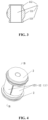
- FIG. 4 a schematic diagram of a three-dimensional structure of the bushing according to an embodiment of the present application is shown in FIG. 4 .
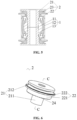
- a cross-sectional view taken along B-B line in FIG. 4 is shown in FIG. 5 .
- the bushing further includes a bushing component 2, both ends of the bushing body 1 are respectively provided with the bushing component 2, and the two bushing components 2 are symmetrically arranged, one (upper) bushing component 2 is in interference fit with one end (upper end) of the bushing body 1, and the other (lower) bushing component 2 is in interference fit with the other end (lower end) of the bushing body 1.
- the bushing provided in this way has a simple structure, and the force on both ends of the bushing is balanced.
- FIG. 6 a schematic diagram of a three-dimensional structural of the bushing component in the bushing according to an embodiment of the present application is shown in FIG. 6
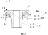
- FIG. 7 is a cross-sectional taken along C-C line in FIG. 6
- the bushing component 2 is a hollow tubular column structure.
- Each of the two bushing components 2 includes a second inner tube 21, a second outer tube 22 and a second rubber body 23, the second outer tube 22 is sleeved on an outer wall of the second inner tube 21, a third gap exists between the second outer tube 22 and the second inner tube 21, and the second rubber body 23 is disposed in the third gap for connecting the second inner tube 21 and the second outer tube 22 by vulcanizing.
- One end of the first inner tube 11 is sleeved on the outer wall of one of the second inner tubes 21 and is in interference fit with the one of the second inner tubes 21, and the other end of the first inner tube 11 is sleeved on the outer wall of the other second inner tube 21 and is in interference fit with the other second inner tube 21.
- the one of the second outer tubes 22 is sleeved on the one end of the outer wall of the first outer tube 12 and is in interference fit with one end of the outer wall of the first outer tube 12, and the other second outer tube 22 is sleeved on the other end of the outer wall of the first outer tube 12 and is in interference fit with the other end of the outer wall of the first outer tube 12.
- the bushing component 2 includes a second inner tube 21, a second outer tube 22 and a second rubber body 23.
- the second outer tube 22 is sleeved on an outer wall of the second inner tube 21, and a third gap exists between the second outer tube 22 and the second inner tube 21.
- the second rubber body 23 is disposed in the third gap, and the second inner tube 21 and the second outer tube 22 are connected together by means of the second rubber body 23 by vulcanizing.
- two bushing components 2 are symmetrically arranged at the upper and lower ends of the bushing body 1 according to the illustrated direction.
- One end (upper end) of the first inner tube 11 is sleeved on the outer wall of the second inner tube 21 of one bushing component 2, and the upper end of the first inner tube 11 is in interference fit with the second inner tube 21 of one bushing component 1 by means of pressing, so that the upper end of the first inner pipe 11 is in tight fit with the axial direction of the second inner pipe 21 in one bushing component 2.
- the other end (lower end) of the first inner tube 11 is sleeved on the outer wall of the second inner tube 21 of the other bushing component 2, and the lower end of the first inner tube 11 is in interference fit with the second inner tube 21 of the other bushing component 2 by means of pressing, so that the lower end of the second inner tube 11 is in axially tight fit with the second inner tube 21 of the other bushing component 2.
- the second outer tube 22 of one bushing component 2 is sleeved at one end (upper end) of the outer wall of the first outer tube 12, and the second outer tube 22 of one bushing component 2 is in interference fit with the upper end of the outer wall of the first outer tube 12 by means of pressing, so that the second outer tube 22 of one bushing component 2 is in axially tight fit with the upper end of the first outer tube 12.
- the second outer tube 22 of the other bushing component 2 is sleeved on the other end (lower end) of the outer wall of the first outer tube 12, and the second outer tube 22 of the other bushing component 2 is in interference fit with the lower end of the outer wall of the first outer tube 12 by means of pressing, so that the second outer tube 22 of the other bushing component 2 is in axially tight fit with the lower end of the first outer tube 12.
- the interference fit relationship between the two bushing components 2 and the bushing body 1 in the present embodiment may avoid the squeeze and friction between the cover and the rubber body in the existing bushing, and the bushing in the present embodiment has good fatigue durability, and wear failure may not be caused after long-term use, so that the service life of the bushing is prolonged.
- the second rubber body 23 of one bushing component 2 when the bushing is subjected to the axial force F axial , the second rubber body 23 of one bushing component 2, the first rubber body 13 of the bushing body 1 and the second rubber body 23 of the other bushing component 2 are simultaneously squeezed.
- the second rubber body 23 is squeezed by the second inner tube 21 and the second outer tube 22 to make the axial rigidity to be increased, that is, the force F1 and the force -F1 squeeze the second rubber body 23, the axial rigidity of the second rubber body 23 increases.
- the axial rigidity increase generated by the second rubber body 23 of the lower bushing component 2 has the same principle as that generated by the second rubber body 23 of the upper bushing component 2, and a magnitude of the rigidity increase amount is the same.
- the first rubber body 13 is squeezed by the first inner tube 11 and the first outer tube 12 to make axial rigidity to be increased, that is, the first rubber body 12 is squeezed by the force F2 and the force -F2, and the first rubber body 13 is sheared to make axial rigidity to be increased.
- the axial rigidity of the bushing in the present embodiment is a sum of axial rigidity provided by the first rubber body 13 and axial rigidity provided by the two second rubber bodies 23. Compared with the conventional technology, the bushing in the present embodiment may provide larger axial rigidity.
- the first rubber body 13 squeezes the first rubber body 13 by means of the first inner tube 11 and the first outer tube 12 to make radial rigidity to be increased, that is, the first rubber body 13 is squeezed by the force F3 and the force -F3, and the first rubber body 13 is compressed to make radial rigidity to be increased.
- the rigidity increase generated by the rubber is compressed is larger than a rigidity increase amount generated by the rubber is sheared, that is to say, the radial rigidity increase amount generated by compression of the first rubber body 13 is larger than the axial rigidity increase amount generated by the first rubber body 13 is sheared.
- the bushing of the present embodiment has larger radial rigidity and axial rigidity, so that the handling stability of a vehicle may be improved.
- each of the second inner tubes 21 includes a second inner tube body 211 and a first annular end seat 212 which are coaxially arranged.
- the first annular end seat 212 is disposed at one end of the second inner tube body 211 away from the bushing body 1, and a cross-sectional area of the first annular end seat 212 is larger than that of the second inner tube body 211.
- One end of the first inner tube 11 is sleeved on the outer wall of one of the second inner tube bodies 211 and is in interference fit with the one of the second inner tube bodies 211, and the other end of the first inner tube 11 is sleeved on the outer wall of the other second inner tube body 211 and is in interference fit with the other second inner tube body 211.
- the second inner tube 21 includes a second inner tube body 211 and a first annular end seat 212 coaxially arranged.
- the first annular end seat 212 is disposed at one end of the second inner tube body 211 away from the bushing body 1.
- a cross-sectional area of the first annular end seat 212 is larger than that of the second inner tube body 211, that is, a diameter of the first annular end seat 212 is larger than that of the second inner tube body 211.
- the upper end of the first inner tube 11 is sleeved on the outer wall of the second inner tube body 211 of the upper bushing component 2, and the upper end of the first inner tube 11 is in interference fit with the second inner tube body 211 of the upper bushing component 2 by pressing, so that the upper end of the first inner pipe 11 is in tight fit with the axial direction of the second inner pipe body 211 of the upper bushing component 2.
- the lower end of the first inner tube 11 is sleeved on the outer wall of the second inner tube body 211 of the lower bushing component 2, and the lower end of the first inner tube 11 is in interference fit with the second inner tube body 211, so that the lower end of the first inner tube 11 is in tight fit with the axial direction of the second inner tube body 211 of the lower bushing component 2.
- the second outer tube 22 is sleeved on the second inner tube body 211 and includes a second outer tube body 22) and a second annular end seat 222 which are coaxially arranged.
- the second outer tube body 221 is away from the first annular end seat 212, the second annular end seat 222 is close to the first annular end seat 212, and a cross-sectional area of the second annular end seat 222 is larger than that of the second outer tube body 221.
- One end of one of the second outer tube bodies 221 away from the second annular end seat 222 is sleeved on one end of the outer wall of the first outer tube 12 and is in interference fit with one end of the outer wall of the first outer tube 12, and the other end of the other second outer tube body 221 away from the second annular end seat 222 is sleeved on the other end of the outer wall of the first outer tube and is in interference fit with the other end of the outer wall of the first outer tube 12.
- the second outer tube 22 includes a second outer tube body 221 and a second annular end seat 222 which are coaxially arranged.
- the second outer tube body 221 is away from the first annular end seat 212, and the second annular end seat 222 is close to the first annular end seat 212.
- a cross-sectional area of the second annular end seat 222 is larger than that of the second outer tube body 221, that is, a diameter of the second annular end seat 222 is larger than that of the second outer tube.
- One end of one of the second outer tube bodies 221 away from the second annular end seat 222 is sleeved on one end of the outer wall of the first outer tube 12, and is in interference fit with one end of the outer wall of the first outer tube 12, so that the upper end of the first outer tube 12 is axially tight fit with the second outer tube body 211 of the upper bushing component 2.
- one end of the other second outer tube body 221 away from the second annular end seat 222 is sleeved on the other end of the outer wall of the first outer tube 12, and is in interference fit with the other end of the outer wall of the first outer tube 12, so that the lower end of the first outer tube 12 is in axially tight fit with the second outer tube body 211 of the lower bushing component 2.
- a third sub-gap exists between the outer wall of the second inner tube body 211 and an inner wall of the second outer tube body 221, and a fourth sub-gap exists between an end face of the first annular end seat 212 away from the bushing body 1 and an end face of the second annular end seat 222 away from the bushing body 1
- the third gap is formed by the third sub-gap and the fourth sub-gap.
- a third sub-gap exists between the outer wall of the second inner tube body (211) and the inner wall of the second outer tube body (221), and a fourth sub-gap exists between the end face of the first annular end seat (212) and the end face of the second annular end seat (222) away from the bushing body (1).
- the third gap is formed by the third sub-gap and the fourth sub-gap.
- the bushing according to the present embodiment may have large axial rigidity, and the problem that the axial rigidity changes discontinuously due to the idle stroke during an existing rubber body being squeezed may be avoided.
- the axial rigidity of the bushing in the embodiment changes continuously, so that the driving smoothness of a vehicle may be improved.
- a length of the second outer tube 22 is shorter than that of the second inner tube body 211, and the position where the second outer tube 22 is sleeved on the outer wall of the second inner tube body 211 is related to sizes of the third sub-gap and the fourth sub-gap, and the sizes of the third sub-gap and the fourth sub-gap are related to the structure of the second rubber body, and the structure of the second rubber body 23 is related to a magnitude of the axial rigidity of the bushing component 2.
- the specific position where the second outer tube 22 is sleeved on the outer wall of the second inner tube body 211 may not be limited, and may be set according to the magnitude of the axial rigidity of the actual requirement.
- the specific shape of the second rubber body 23 (the shape of the second rubber body 23 shown in the figure is irregular) may not be limited in the present embodiment, and the second rubber body 23 may completely fill the third sub-gap and the fourth sub-gap, or may also fill portions of the third sub-gap and the fourth sub-gap. But the continuity of the two second rubber bodies 23 and the first rubber body 13 in the axial direction needs to be ensured.
- the specific structure of the second rubber body 23 is set according to the magnitude of the axial rigidity of the actual requirement.
- the second outer tube body 221 includes a first part of second outer tube body 2211 and a second part of second outer tube body 2212, and the first part of second outer tube body 2211 is close to the bushing body 1.
- the second part of second outer tube body 2212 is away from the bushing body 1, and an inner diameter of the first part of second outer tube body 2211 is larger than that of the second part of second outer tube body 2212. That is, a wall thickness of the first part of second outer tube body 2211 is smaller than that of the second part of second outer tube body 2212.
- the first part of second outer tube body 2211 of the upper bushing component 1 is sleeved on the upper end of the outer wall of the first outer tube 12, and the first part of second outer tube body 2211 of the lower bushing component 2 is sleeved on the lower end of the outer wall of the first outer tube 12.
- the upper end of the first inner tube 11 is connected with the lower end of the second outer tube body 221 of the upper bushing component 2.
- the lower end of the first inner tube 11 is sleeved on the outer wall of the second inner tube body 211 of the lower bushing component 2, the lower end of the first inner tube 11 is connected with the lower end of the second outer tube body 221 of the lower bushing component 2, so that the two second rubber bodies 23 may be in a continuous state with the first rubber body 13, thus avoiding the problem that the existing rubber bodies has discontinuous axial rigidity change due to idle stroke during being squeezed.
- the axial rigidity of the bushing in the present embodiment changes continuously, and the driving smoothness of a vehicle may be improved.
- roughness of the lower end face of the second outer tube body 221 of the upper bushing component 2 and the roughness of the upper end face of the second outer tube body 221 of the lower bushing component 2 may be increased.
- a plurality of protruding points 24 may be uniformly disposed on an end face of the second outer tube body 221 away from the bushing body 1, and shapes of the protruding points is at least one of a circle and a rectangle, and the specific shape of the protruding points may be defined according to actual requirements.
- a shape of the protruding structure 111 is arc-shaped, and the arc-shaped is a convex arc relative to the outer wall of the first inner tube.
- a first transition arc 112 is disposed between one end of the protruding structure 111 and one end of the first inner tube 11, and a second transition arc 113 is disposed between the other end of the protruding structure 111 and the other end of the first inner tube 11.
- the convex structure 111 is arc-shaped, and the arc is a convex arc relative to the outer wall of the first inner tube, so that the first inner tube 11 may be regarded as a hollow cylindrical with the axial middle section arched outward.
- a first transition arc 112 is disposed between one end (upper end) of the protruding structure 111 and the upper end of the first inner pipe 11, and a second transition arc 113 is disposed between the other end (lower end) and the lower end of the first inner pipe 11.
- the cross-sectional shape of the first inner pipe 11 is similar to the shape of a lantern, that is, the protruding structure 111 is an arc-shaped protrusion with both flat ends and a parabolic middle section, and the load is evenly distributed along the chord.
- the radial rigidity of the first inner tube 21 may be increased, so that the radial rigidity of the bushing body 1 is increased and the torsional rigidity of the bushing body 1 is reduced, thereby the driving smoothness and handling stability of a vehicle is improved.
- the protruding structure 111 may also be a parabola shape in which the first transition arc 112, the middle arc and the second transition arc 113 are connected, or it may be merely a middle arc, and the arc is a parabola shape.
- the specific shape of the cross-section of the protruding structure 111 may be set according to the actual situation.
- the parabola herein is not exactly the same as the parabola shape in geometry, but merely similar to the parabola shape in geometry.
- the protruding structure 111 is located in a middle area of the outer wall of the first inner tube 11, and both the transition arcs are symmetrically arranged, and the radius of the fillets of the two transition arcs may be as large as possible, so that the fatigue durability of the bushing body 1 may be improved.
- the length of the first gap between two adjacent arc-shaped plates 121 in the present embodiment is between 2-3 mm.
- the first gap may also have other length, and the length of the first gap in the present embodiment is not limited, and the specific length of the first gap needs to be to be set according to the actual situation.
- the bushing according to the present application has at least the following advantages:
- the radial rigidity of the bushing body may be improved, and the torsional rigidity of the bushing body may be reduced.
- the axial rigidity of the bushing body may be increased correspondingly with the increase of the radial rigidity of the bushing body.
- the first outer tube includes a plurality of arc-shaped plates which are distributed at intervals along the circumferential direction of the first outer tube.
- the bushing of the present embodiment may simultaneously satisfy large radial rigidity, large axial rigidity and low torsional rigidity, so that the vehicle may both satisfy driving smoothness and manipulation stability.
- a suspension system is further provided, and the suspension system includes the bushing above-mentioned.
- one end of the control arm is usually connected with the sub-frame by the bushing.
- the bushing is installed in an inner hole of a control arm, and is connected with a sub-frame in the axial direction, and the other end of the control arm is connected with a steering knuckle.
- the transmission direction of force outside the bushing is transverse (left and right direction) as shown in FIG. 4 , and the external load is transmitted to the control arm by means of a tire, and is transmitted to the bushing via the control arm, and is transmitted to the sub-frame subsequently.
- the transmission direction of force is radial and circumferential.
- the suspension system according to the present application has at least the following advantages:
- the suspension system includes the bushing.
- the bushing by disposing the protruding structure on the outer wall of the first inner tube, the radial rigidity of the bushing body may be improved, and the torsional rigidity of the bushing body may be reduced.
- the axial rigidity of the bushing body may increase correspondingly with the increase of the radial rigidity of the bushing body.
- the first outer tube includes a plurality of arc-shaped plates which are distributed at intervals along a circumferential direction of the first outer tube.
- the bushing of the present embodiment may simultaneously satisfy large radial rigidity, large axial rigidity and low torsional rigidity, so that the vehicle may both satisfy the driving smoothness and the manipulation stability.
- a vehicle is further provided, and the vehicle includes the suspension system above-mentioned.
- the vehicle includes the suspension system, and the suspension system includes the bushing.
- the specific structure and operation principle of the bushing have been described in detail above, and will not be repeated herein.
- the vehicle Compared with the conventional technology, the vehicle has the same advantages as the suspension system, which are not described in detail herein.
Landscapes
- Engineering & Computer Science (AREA)
- General Engineering & Computer Science (AREA)
- Mechanical Engineering (AREA)
- Manufacturing & Machinery (AREA)
- Health & Medical Sciences (AREA)
- Child & Adolescent Psychology (AREA)
- Springs (AREA)
Abstract
Description
- The present application claims the priority of the Chinese patent application filed on March 1th, 2021 before the CNIPA (China National Intellectual Property Administration) with the application number of
202110225588.0 - The present application relates to the technical field of vehicle components and, more particularly, to a bushing, suspension system and vehicle.
- A suspension system is an important component on a vehicle, which plays a crucial role in driving smoothness and handling stability of the vehicle. As an important element of the suspension system for carrying loads, a control arm is generally connected with a sub-frame of the vehicle by means of a bushing. Therefore, as a hub, the bushing is subjected to relatively complex force in the movement process of the vehicle, mainly bears axial and radial force during accelerating and braking, and needs to follow the suspension system to move, so that produce torsional moment is generated.
- In practical application, under the condition that the vehicle is required to have good handling stability, the bushing needs to provide large radial rigidity and large axial rigidity, and under the condition that the vehicle is required to have good driving smoothness, the bushing needs to provide low torsional rigidity. However, in the conventional technology, it is difficult for the bushing to satisfy the large radial rigidity, the large axial rigidity and the low torsional rigidity at the same time, so that the vehicle is difficult to satisfy both the driving smoothness and the operation stability.
- In view of the above, the present application aims to provide a bushing, to solve a technical problem that it is difficult for the bushing to satisfy large radial rigidity, large axial rigidity and low torsional rigidity at the same time, causing the vehicle is difficult to satisfy both driving smoothness and operation stability.
- In order to achieve the above-mentioned purpose, the technical solutions of the present application are realized as follows:
- A bushing, including a bushing body, wherein the bushing body includes a first inner tube, a first outer tube and a first rubber body;
- an outer wall of the first inner tube is provided with a protruding structure;
- the first outer tube includes a plurality of arc-shaped plates, the plurality of arc-shaped plates are distributed at intervals along a circumferential direction of the first outer tube, a first gap exists between two adjacent arc-shaped plates, the first outer tube is sleeved on the outer wall of the first inner tube, and a second gap exists between the first outer tube and the first inner tube;
- the first rubber body is disposed in the second gap and for connecting the first inner tube and the first outer tube by vulcanizing.
- Further, the plurality of the arc-shaped plates are evenly distributed.
- Further, the bushing further includes a bushing component;
both ends of the bushing body are respectively provided with the bushing component, and the two bushing components are symmetrically arranged, one bushing component is in interference fit with one end of the bushing body, and the other bushing component is in interference fit with the other end of the bushing body. - Further, each of two the bushing components includes a second inner tube, a second outer tube and a second rubber body;
- the second outer tube is sleeved on an outer wall of the second inner tube, a third gap exists between the second outer tube and the second inner tube, and the second rubber body is disposed in the third gap for connecting the second inner tube and the second outer tube by vulcanizing;
- one end of the first inner tube is sleeved on the outer wall of one of the second inner tubes (herein after, sometimes also referred as "one second inner tube") and is in interference fit with the one of the second inner tube, and the other end of the first inner tube is sleeved on the outer wall of the other second inner tube and is in interference fit with the other second inner tube;
- one of second outer tubes (herein after, sometimes also referred as "one second outer tube") is sleeved on the one end of the outer wall of the first outer tube and is in interference fit with the one end of the outer wall of the first outer tube, and the other second outer tube is sleeved on the other end of the outer wall of the first outer tube and is in interference fit with the other end of the outer wall of the first outer tube.
- Further, each of the second inner tubes includes a second inner tube body and a first annular end seat which are coaxially arranged;
- the first annular end seat is disposed at one end of the second inner tube body away from the bushing body, and a cross-sectional area of the first annular end seat is larger than that of the second inner tube body;
- one end of the first inner tube is sleeved on an outer wall of one of the second inner tube bodies and is in interference fit with the one of the second inner tube bodies, and the other end of the first inner tube is sleeved on an outer wall of the other second inner tube body and is in interference fit with the other second inner tube body.
- Further, the second outer tube is sleeved on the second inner tube body and includes a second outer tube body and a second annular end seat which are coaxially arranged;
- the second outer tube body is away from the first annular end seat, the second annular end seat is close to the first annular end seat, and a cross-sectional area of the second annular end seat is larger than that of the second outer tube body;
- one end of one of the second outer tube bodies (herein after, sometimes also referred as "one second outer tube body") away from the second annular end seat is sleeved on one end of the outer wall of the first outer tube and is in interference fit with one end of the outer wall of the first outer tube, and the other end of the other second outer tube body away from the second annular end seat is sleeved on the other end of the outer wall of the first outer tube and is in interference fit with the other end of the outer wall of the first outer tube.
- Further, a third sub-gap exists between the outer wall of the second inner tube body and an inner wall of the second outer tube body;
- a fourth sub-gap exists between an end face of the first annular end seat away from the bushing body and an end face of the second annular end seat away from the bushing body;
- the third gap is formed by the third sub-gap and the fourth sub-gap.
- Further, in an axial direction of the first inner tube, a shape of the protruding structure is arc-shaped, and the arc-shaped is a convex arc relative to the outer wall of the first inner tube;
a first transition arc is disposed between one end of the protruding structure and one end of the first inner tube, and a second transition arc is disposed between the other end of the protruding structure and the other end of the first inner tube. - Compared with the conventional technology, the bushing according to the present application has at least the following advantages:
- In the embodiment of the present application, by disposing the protruding structure on the outer wall of the first inner tube, the radial rigidity of the bushing body may be improved, and the torsional rigidity of the bushing body may be reduced. In practical application, the axial rigidity of the bushing body may be increased correspondingly with the increase of the radial rigidity of the bushing body. The first outer tube includes a plurality of arc-shaped plates which are distributed at intervals along a circumferential direction of the first outer tube. Since a first gap exists between two adjacent arc-shaped plates, in this way, under the condition that the bushing body squeezes the first rubber body in the process of using, the compression amount of the first rubber body is increased, so that the torsional rigidity of the bushing body may be reduced. It may be seen that, the bushing of the present embodiment may simultaneously satisfy large radial rigidity, large axial rigidity and low torsional rigidity, so that a vehicle may both satisfy driving smoothness and manipulation stability.
- Another purpose of the present application is to provide a suspension system, to solve the technical problem that it is difficult for the bushing to satisfy the large radial rigidity, the large axial rigidity and the low torsional rigidity at the same time, causing the vehicle is difficult to satisfy both the driving smoothness and the operation stability.
- In order to achieve the above-mentioned purpose, the technical solutions of the present application are realized as follows:
a suspension system, including the bushing above-mentioned. - Compared with the conventional technology, the suspension system has the same advantages as the bushing, and details are not described herein again.
- Another purpose of the present application is to provide a vehicle, to solve the technical problem that it is difficult for the bushing to satisfy the large radial rigidity, the large axial rigidity and the low torsional rigidity at the same time, causing the vehicle is difficult to satisfy both the driving smoothness and the operation stability.
- In order to achieve the above-mentioned purpose, the technical solutions of the present application are realized as follows:
a vehicle, including the suspension system above-mentioned. - Compared with the conventional technology, the vehicle has the same advantages as the suspension system, and details are not described herein again.
- The drawings, which constitute a portion of the present application, are intended to provide a further interpretation of the present application. The illustrative embodiments of the present application and their explanation are intended to interpret the present application, and do not inappropriately limit the present application. In the drawings:
-
FIG. 1 is a schematic diagram of a three-dimensional structure of a bushing body in the bushing according to an embodiment of the present application; -
FIG. 2 is a cross-sectional view taken along A-A line inFIG. 1 ; -
FIG. 3 is a cross-sectional view of a first inner tube of the bushing body inFIG. 2 ; -
FIG. 4 is a schematic diagram of a three-dimensional structure of a bushing according to an embodiment of the present application; -
FIG. 5 is a cross-sectional view taken along B-B line inFIG. 4 ; -
FIG. 6 is a schematic diagram of a three-dimensional structure of a bushing component in the bushing according to an embodiment of the present application; and -
FIG. 7 is a cross-sectional view taken along C-C line inFIG. 6 . - 1- bushing body, 11- first inner tube, 12- first outer tube, 13- first rubber body, 111-protruding structure, 112- first transition arc, 113- second transition arc, 121- arc-shaped plate, 122- first gap, 2- bushing component, 21- second inner tube, 211- second inner tube body, 212-first annular end seat, 22- second outer tube, 221- second outer tube body, 2211- first part of second outer tube body, 2212- second part of second outer tube body, 222- second annular end seat, 23- second rubber body, 24- protruding point.
- It should be noted that, subject to the avoiding of any conflict, embodiments and features of the embodiments of the present application may be combined.
- In the conventional technology, a bushing has a shape of cylindrical, and includes an inner tube, an outer tube and a rubber body, wherein the outer tube is sleeved on the outer wall of the inner tube, and the rubber body connects an inner wall of the outer tube with the outer wall of the inner tube by means of a vulcanization process. The bushing mainly bears axial force and radial force in the process of accelerating and braking of the vehicle, and needs to follow a suspension system to move to generate a torsional moment. Therefore, the bushing needs to have the following characteristics: radial static rigidity, axial static rigidity and torsional rigidity. The radial static rigidity Xradial: is a ratio of force applied in a radial direction force Fradial (the inner tube is fixed and the force is applied on the outer tube) to a radial displacement Sradial, that is, Xradial =Fradial /Sradial. The axial static rigidity Zaxial: is a ratio of force applied along an axial direction Faxial (the outer tube is fixed and the force is applied on the inner tube) to a axial displacement Saxial, that is, Zaxial =Faxial /Saxial. The torsional rigidity Taxial: is a ratio of torque Maxial rotating along the axial direction Z (the inner tube is fixed and the force is applied on the outer tube) to a rotation angle Aaxial, that is, Taxial =Maxial / Aaxial.
- For existing bushings, the radial rigidity of the bushing is generally adjusted by adjusting hardness and structure of the rubber body, and the axial rigidity and torsional rigidity may be increased with the increase of the radial rigidity. However, the adjustment of the hardness and structure of the rubber body has no obvious effect on the increase of the axial rigidity, it is almost impossible to be achieved especially for bushings with axial rigidity of 5000 N/mm or more.
- In some existing bushings, a cover is disposed at one end of the bushing, and the axial rigidity is made to be increased by the inner tube and the outer tube squeezing the rubber body, and the rubber is compressed to make the rigidity to be increased. Although this structure may generate rubber compression, in an axial direction, since a gap exists between an end of the rubber body close to the cover, so that the end of the rubber body close to the cover and the cover squeeze the rubber may not generate a particularly large increase amount in rigidity, and an idle stroke exists before the rigidity is increased, causing discontinuous rigidity change, and affecting driving smoothness of a vehicle. In addition, the end of the rubber body away from the cover and the cover squeeze the rubber body, so that the rubber is sheared to generate rigidity change, but it does not generate a particularly large increase amount in rigidity.
- In addition, in a use process of the existing bushing, the cover may be squeezed and rubbed with the rubber body, so that the existing bushing has poor durability, and wear failure may occur after long-term use.
- Hereinafter, the present application will be described in detail with reference to the drawings and embodiments.
- In the embodiment of the present application, referring to
FIGs. 1 to 3 ,FIG. 1 shows a schematic diagram of a three-dimensional structure of a bushing body in the bushing described in an embodiment of the present application,FIG. 2 is a cross-sectional view taken along A-A line inFIG. 1 , andFIG. 3 is a cross-sectional view of a first inner tube of the bushing body inFIG. 2 . The present embodiment provides a bushing, which may particularly include a firstinner tube 11, a firstouter tube 12 and afirst rubber body 13;an outer wall of the firstinner tube 11 is provided with a protrudingstructure 111 The firstouter tube 12 includes a plurality of arc-shapedplates 121, the plurality of arc-shapedplates 121 are distributed at intervals along a circumferential direction of the firstouter tube 12, a first gap exists between two adjacent arc-shapedplates 121, the firstouter tube 12 is sleeved on an outer wall of the firstinner tube 11, and a second gap exists between the firstouter tube 12 and the firstinner tube 11. Thefirst rubber body 13 is disposed in the second gap and for connecting the firstinner tube 11 and the firstouter tube 12 by vulcanizing. - Particularly, as shown in
FIGs. 1 to 3 , the firstinner tube 11 is a hollow cylinder, and the firstouter tube 12 includes a plurality of arc-shapedplates 121, which are distributed at intervals along a circumferential direction of the firstouter tube 12, that is, the shape of the firstouter tube 12 surrounded by the plurality of arc-shapedplates 121 is also a hollow cylinder, and the firstouter tube 12 is sleeved on the outer wall of the firstinner tube 11, and the second gap exists between the firstouter tube 12 and the firstinner tube 11. Thefirst rubber body 13 is disposed in the second gap and for connecting the firstinner tube 11 and the firstouter tube 12 by vulcanizing. Of course, in the present embodiment, the specific shapes of the firstouter tube 12 and the firstinner tube 11 may not be limited, and they may also be other shapes, for example a hollow elliptical column and the like, and the specific shapes may be adopted according to the actual situation. It should be noted that, the present embodiment will be described below by taking a hollow cylinder as an example. - Particularly, as shown in
FIGs. 2 and3 , a protrudingstructure 111 is disposed on the outer wall of the firstinner tube 11, so that the protrudingstructure 111 may increase the radial rigidity of thebushing body 1 and reduce the torsional rigidity of thebushing body 1. In practical application, the axial rigidity of thebushing body 1 may increase correspondingly with the increase of the radial rigidity of thebushing body 1. As shown inFIGs. 1 and 2 , since the first gap exists between two adjacent arc-shapedpieces 121, under the condition that thebushing body 1 squeezes thefirst rubber body 13 during use, the compression amount of thefirst rubber body 13 is increased compared with the conventional technology, so that the torsional rigidity of thebushing body 1 may be reduced, and the fatigue durability of thebushing body 1 may also be improved. It may be seen that, the bushing of the present embodiment may have large radial rigidity, large axial rigidity and low torsional rigidity at the same time, so that the vehicle may both satisfy good driving smoothness and manipulation stability. - According to the embodiment of the present application, the plurality of arc-shaped
plates 121 are evenly distributed, so that under the condition that thebushing body 1 squeezes thefirst rubber body 13 during use, the more evenly thefirst rubber body 13 being squeezed, the better the fatigue durability of thebushing body 1. It should be noted that, two arc-shapedplates 121 are shown in the present embodiment. Of course, other number of arc-shaped plates may also be provided, for example, four arc-shapedplates 121, six arc-shapedplates 121 and the like, and the specific number of arc-shapedplates 121 is not limited in the present embodiment. In practical application, the more the number of arc-shapedplates 121, the more evenly thefirst rubber body 13 is squeezed, and the better the fatigue durability of thebushing body 1. However, the more the number of arc-shapedplates 121 is, the higher the cost will be. Therefore, in the present embodiment, the number of arc-shapedplates 121 is preferably two for cost consideration. - In an embodiment of the present application, referring to
FIGs. 1 to 5 , a schematic diagram of a three-dimensional structure of the bushing according to an embodiment of the present application is shown inFIG. 4 . A cross-sectional view taken along B-B line inFIG. 4 is shown inFIG. 5 . The bushing further includes abushing component 2, both ends of thebushing body 1 are respectively provided with thebushing component 2, and the twobushing components 2 are symmetrically arranged, one (upper)bushing component 2 is in interference fit with one end (upper end) of thebushing body 1, and the other (lower)bushing component 2 is in interference fit with the other end (lower end) of thebushing body 1. The bushing provided in this way has a simple structure, and the force on both ends of the bushing is balanced. - According to the embodiment of the present application, referring to
FIGs. 1 to 7 , a schematic diagram of a three-dimensional structural of the bushing component in the bushing according to an embodiment of the present application is shown inFIG. 6 , andFIG. 7 is a cross-sectional taken along C-C line inFIG. 6 , wherein thebushing component 2 is a hollow tubular column structure. Each of the twobushing components 2 includes a secondinner tube 21, a secondouter tube 22 and asecond rubber body 23, the secondouter tube 22 is sleeved on an outer wall of the secondinner tube 21, a third gap exists between the secondouter tube 22 and the secondinner tube 21, and thesecond rubber body 23 is disposed in the third gap for connecting the secondinner tube 21 and the secondouter tube 22 by vulcanizing. One end of the firstinner tube 11 is sleeved on the outer wall of one of the secondinner tubes 21 and is in interference fit with the one of the secondinner tubes 21, and the other end of the firstinner tube 11 is sleeved on the outer wall of the other secondinner tube 21 and is in interference fit with the other secondinner tube 21. The one of the secondouter tubes 22 is sleeved on the one end of the outer wall of the firstouter tube 12 and is in interference fit with one end of the outer wall of the firstouter tube 12, and the other secondouter tube 22 is sleeved on the other end of the outer wall of the firstouter tube 12 and is in interference fit with the other end of the outer wall of the firstouter tube 12. - Particularly, as shown in
FIGs. 6 and7 , thebushing component 2 includes a secondinner tube 21, a secondouter tube 22 and asecond rubber body 23. The secondouter tube 22 is sleeved on an outer wall of the secondinner tube 21, and a third gap exists between the secondouter tube 22 and the secondinner tube 21. Thesecond rubber body 23 is disposed in the third gap, and the secondinner tube 21 and the secondouter tube 22 are connected together by means of thesecond rubber body 23 by vulcanizing. - Particularly, as shown in
FIGs. 4 and5 , twobushing components 2 are symmetrically arranged at the upper and lower ends of thebushing body 1 according to the illustrated direction. One end (upper end) of the firstinner tube 11 is sleeved on the outer wall of the secondinner tube 21 of onebushing component 2, and the upper end of the firstinner tube 11 is in interference fit with the secondinner tube 21 of onebushing component 1 by means of pressing, so that the upper end of the firstinner pipe 11 is in tight fit with the axial direction of the secondinner pipe 21 in onebushing component 2. Similarly, the other end (lower end) of the firstinner tube 11 is sleeved on the outer wall of the secondinner tube 21 of theother bushing component 2, and the lower end of the firstinner tube 11 is in interference fit with the secondinner tube 21 of theother bushing component 2 by means of pressing, so that the lower end of the secondinner tube 11 is in axially tight fit with the secondinner tube 21 of theother bushing component 2. The secondouter tube 22 of onebushing component 2 is sleeved at one end (upper end) of the outer wall of the firstouter tube 12, and the secondouter tube 22 of onebushing component 2 is in interference fit with the upper end of the outer wall of the firstouter tube 12 by means of pressing, so that the secondouter tube 22 of onebushing component 2 is in axially tight fit with the upper end of the firstouter tube 12. Similarly, the secondouter tube 22 of theother bushing component 2 is sleeved on the other end (lower end) of the outer wall of the firstouter tube 12, and the secondouter tube 22 of theother bushing component 2 is in interference fit with the lower end of the outer wall of the firstouter tube 12 by means of pressing, so that the secondouter tube 22 of theother bushing component 2 is in axially tight fit with the lower end of the firstouter tube 12. Compared with the conventional technology, the interference fit relationship between the twobushing components 2 and thebushing body 1 in the present embodiment may avoid the squeeze and friction between the cover and the rubber body in the existing bushing, and the bushing in the present embodiment has good fatigue durability, and wear failure may not be caused after long-term use, so that the service life of the bushing is prolonged. - Particularly, when the bushing is subjected to the axial force Faxial, the
second rubber body 23 of onebushing component 2, thefirst rubber body 13 of thebushing body 1 and thesecond rubber body 23 of theother bushing component 2 are simultaneously squeezed. As shown inFIG. 7 , for one bushing component 2 (upper bushing component), thesecond rubber body 23 is squeezed by the secondinner tube 21 and the secondouter tube 22 to make the axial rigidity to be increased, that is, the force F1 and the force -F1 squeeze thesecond rubber body 23, the axial rigidity of thesecond rubber body 23 increases. Since the other bushing component 2 (lower bushing component) is symmetrically arranged with theupper bushing component 2, the axial rigidity increase generated by thesecond rubber body 23 of thelower bushing component 2 has the same principle as that generated by thesecond rubber body 23 of theupper bushing component 2, and a magnitude of the rigidity increase amount is the same. As shown inFIG. 2 , for thebushing body 1, thefirst rubber body 13 is squeezed by the firstinner tube 11 and the firstouter tube 12 to make axial rigidity to be increased, that is, thefirst rubber body 12 is squeezed by the force F2 and the force -F2, and thefirst rubber body 13 is sheared to make axial rigidity to be increased. It may be seen that, the axial rigidity of the bushing in the present embodiment is a sum of axial rigidity provided by thefirst rubber body 13 and axial rigidity provided by the twosecond rubber bodies 23. Compared with the conventional technology, the bushing in the present embodiment may provide larger axial rigidity. - Particularly, as shown in
FIG. 2 , for thebushing body 1, thefirst rubber body 13 squeezes thefirst rubber body 13 by means of the firstinner tube 11 and the firstouter tube 12 to make radial rigidity to be increased, that is, thefirst rubber body 13 is squeezed by the force F3 and the force -F3, and thefirst rubber body 13 is compressed to make radial rigidity to be increased. In practical application, according to the characteristics of rubber, the rigidity increase generated by the rubber is compressed is larger than a rigidity increase amount generated by the rubber is sheared, that is to say, the radial rigidity increase amount generated by compression of thefirst rubber body 13 is larger than the axial rigidity increase amount generated by thefirst rubber body 13 is sheared. Moreover, since the outer wall of the firstinner tube 11 is provided with the protrudingstructure 111, large radial rigidity may be achieved. Compared with the conventional technology, the bushing of the present embodiment has larger radial rigidity and axial rigidity, so that the handling stability of a vehicle may be improved. - In an alternative embodiment of the present application, as shown in
FIGs. 6 and7 , each of the secondinner tubes 21 includes a secondinner tube body 211 and a firstannular end seat 212 which are coaxially arranged. The firstannular end seat 212 is disposed at one end of the secondinner tube body 211 away from thebushing body 1, and a cross-sectional area of the firstannular end seat 212 is larger than that of the secondinner tube body 211. One end of the firstinner tube 11 is sleeved on the outer wall of one of the secondinner tube bodies 211 and is in interference fit with the one of the secondinner tube bodies 211, and the other end of the firstinner tube 11 is sleeved on the outer wall of the other secondinner tube body 211 and is in interference fit with the other secondinner tube body 211. - Particularly, as shown in
FIGs. 6 and7 , since the twobushing components 2 are symmetrically arranged, theupper bushing component 2 shown in the figure will be used as an explanation, and thelower bushing component 2 merely needs to refer to theupper bushing component 2. The secondinner tube 21 includes a secondinner tube body 211 and a firstannular end seat 212 coaxially arranged. The firstannular end seat 212 is disposed at one end of the secondinner tube body 211 away from thebushing body 1. As shown inFIGs 4 and5 , a cross-sectional area of the firstannular end seat 212 is larger than that of the secondinner tube body 211, that is, a diameter of the firstannular end seat 212 is larger than that of the secondinner tube body 211. - Particularly, as shown in
FIGs. 4 to 7 , the upper end of the firstinner tube 11 is sleeved on the outer wall of the secondinner tube body 211 of theupper bushing component 2, and the upper end of the firstinner tube 11 is in interference fit with the secondinner tube body 211 of theupper bushing component 2 by pressing, so that the upper end of the firstinner pipe 11 is in tight fit with the axial direction of the secondinner pipe body 211 of theupper bushing component 2. Similarly, the lower end of the firstinner tube 11 is sleeved on the outer wall of the secondinner tube body 211 of thelower bushing component 2, and the lower end of the firstinner tube 11 is in interference fit with the secondinner tube body 211, so that the lower end of the firstinner tube 11 is in tight fit with the axial direction of the secondinner tube body 211 of thelower bushing component 2. - According to an embodiment of the present application, as shown in
FIGs. 4 to 7 , the secondouter tube 22 is sleeved on the secondinner tube body 211 and includes a second outer tube body 22) and a secondannular end seat 222 which are coaxially arranged. The secondouter tube body 221 is away from the firstannular end seat 212, the secondannular end seat 222 is close to the firstannular end seat 212, and a cross-sectional area of the secondannular end seat 222 is larger than that of the secondouter tube body 221. One end of one of the secondouter tube bodies 221 away from the secondannular end seat 222 is sleeved on one end of the outer wall of the firstouter tube 12 and is in interference fit with one end of the outer wall of the firstouter tube 12, and the other end of the other secondouter tube body 221 away from the secondannular end seat 222 is sleeved on the other end of the outer wall of the first outer tube and is in interference fit with the other end of the outer wall of the firstouter tube 12. - Particularly, as shown in
FIGs. 4 to 7 , the secondouter tube 22 includes a secondouter tube body 221 and a secondannular end seat 222 which are coaxially arranged. The secondouter tube body 221 is away from the firstannular end seat 212, and the secondannular end seat 222 is close to the firstannular end seat 212. A cross-sectional area of the secondannular end seat 222 is larger than that of the secondouter tube body 221, that is, a diameter of the secondannular end seat 222 is larger than that of the second outer tube. One end of one of the secondouter tube bodies 221 away from the secondannular end seat 222 is sleeved on one end of the outer wall of the firstouter tube 12, and is in interference fit with one end of the outer wall of the firstouter tube 12, so that the upper end of the firstouter tube 12 is axially tight fit with the secondouter tube body 211 of theupper bushing component 2. Similarly, one end of the other secondouter tube body 221 away from the secondannular end seat 222 is sleeved on the other end of the outer wall of the firstouter tube 12, and is in interference fit with the other end of the outer wall of the firstouter tube 12, so that the lower end of the firstouter tube 12 is in axially tight fit with the secondouter tube body 211 of thelower bushing component 2. - According to an embodiment of the present application, as shown in
FIGs. 5 and7 , a third sub-gap exists between the outer wall of the secondinner tube body 211 and an inner wall of the secondouter tube body 221, and a fourth sub-gap exists between an end face of the firstannular end seat 212 away from thebushing body 1 and an end face of the secondannular end seat 222 away from thebushing body 1 The third gap is formed by the third sub-gap and the fourth sub-gap. - Particularly, as shown in
FIGs. 5 and7 , a third sub-gap exists between the outer wall of the second inner tube body (211) and the inner wall of the second outer tube body (221), and a fourth sub-gap exists between the end face of the first annular end seat (212) and the end face of the second annular end seat (222) away from the bushing body (1). The third gap is formed by the third sub-gap and the fourth sub-gap. In this way, viewed from the axial direction, thesecond rubber body 23 of theupper bushing component 2, thefirst rubber body 13 of the bushingmain body 1 and thesecond rubber body 23 of thelower bushing component 2 are in a continuous state, and the total axial rigidity increase amount of the bushing is a sum of the axial rigidity increase amounts generated by the three rubber bodies are squeezed respectively. Compared with the conventional technology, the bushing according to the present embodiment may have large axial rigidity, and the problem that the axial rigidity changes discontinuously due to the idle stroke during an existing rubber body being squeezed may be avoided. The axial rigidity of the bushing in the embodiment changes continuously, so that the driving smoothness of a vehicle may be improved. - Further, in the axial direction, as shown in
FIGs. 5 and7 , a length of the secondouter tube 22 is shorter than that of the secondinner tube body 211, and the position where the secondouter tube 22 is sleeved on the outer wall of the secondinner tube body 211 is related to sizes of the third sub-gap and the fourth sub-gap, and the sizes of the third sub-gap and the fourth sub-gap are related to the structure of the second rubber body, and the structure of thesecond rubber body 23 is related to a magnitude of the axial rigidity of thebushing component 2. Therefore, in the present embodiment, the specific position where the secondouter tube 22 is sleeved on the outer wall of the secondinner tube body 211 may not be limited, and may be set according to the magnitude of the axial rigidity of the actual requirement. In addition, the specific shape of the second rubber body 23 (the shape of thesecond rubber body 23 shown in the figure is irregular) may not be limited in the present embodiment, and thesecond rubber body 23 may completely fill the third sub-gap and the fourth sub-gap, or may also fill portions of the third sub-gap and the fourth sub-gap. But the continuity of the twosecond rubber bodies 23 and thefirst rubber body 13 in the axial direction needs to be ensured. The specific structure of thesecond rubber body 23 is set according to the magnitude of the axial rigidity of the actual requirement. - Further, as shown in
FIG. 7 , the secondouter tube body 221 includes a first part of secondouter tube body 2211 and a second part of secondouter tube body 2212, and the first part of secondouter tube body 2211 is close to thebushing body 1. The second part of secondouter tube body 2212 is away from thebushing body 1, and an inner diameter of the first part of secondouter tube body 2211 is larger than that of the second part of secondouter tube body 2212. That is, a wall thickness of the first part of secondouter tube body 2211 is smaller than that of the second part of secondouter tube body 2212. As shown inFIG. 5 , the first part of secondouter tube body 2211 of theupper bushing component 1 is sleeved on the upper end of the outer wall of the firstouter tube 12, and the first part of secondouter tube body 2211 of thelower bushing component 2 is sleeved on the lower end of the outer wall of the firstouter tube 12. In addition, after the upper end of the firstinner tube 11 is sleeved on the outer wall of the secondinner tube body 211 of theupper bushing component 2, the upper end of the firstinner tube 11 is connected with the lower end of the secondouter tube body 221 of theupper bushing component 2. Similarly, after the lower end of the firstinner tube 11 is sleeved on the outer wall of the secondinner tube body 211 of thelower bushing component 2, the lower end of the firstinner tube 11 is connected with the lower end of the secondouter tube body 221 of thelower bushing component 2, so that the twosecond rubber bodies 23 may be in a continuous state with thefirst rubber body 13, thus avoiding the problem that the existing rubber bodies has discontinuous axial rigidity change due to idle stroke during being squeezed. The axial rigidity of the bushing in the present embodiment changes continuously, and the driving smoothness of a vehicle may be improved. - Further, in order to improve the installation stability of the upper end face of the first
outer tube 12 and the lower end face of the secondouter tube body 221 of theupper bushing component 2, and the installation stability of the lower end face of the firstouter tube 12 and the upper end face of the secondouter tube body 221 of thelower bushing component 2, in the present embodiment, roughness of the lower end face of the secondouter tube body 221 of theupper bushing component 2 and the roughness of the upper end face of the secondouter tube body 221 of thelower bushing component 2 may be increased. For the method of increasing the roughness, a plurality of protrudingpoints 24 may be uniformly disposed on an end face of the secondouter tube body 221 away from thebushing body 1, and shapes of the protruding points is at least one of a circle and a rectangle, and the specific shape of the protruding points may be defined according to actual requirements. - According to an embodiment of the present application, in the axial direction of the first
inner tube 11, a shape of the protrudingstructure 111 is arc-shaped, and the arc-shaped is a convex arc relative to the outer wall of the first inner tube. Afirst transition arc 112 is disposed between one end of the protrudingstructure 111 and one end of the firstinner tube 11, and asecond transition arc 113 is disposed between the other end of the protrudingstructure 111 and the other end of the firstinner tube 11. - Particularly, as shown in
FIG. 3 , in the axial direction of the firstinner tube 11, theconvex structure 111 is arc-shaped, and the arc is a convex arc relative to the outer wall of the first inner tube, so that the firstinner tube 11 may be regarded as a hollow cylindrical with the axial middle section arched outward. Moreover, afirst transition arc 112 is disposed between one end (upper end) of the protrudingstructure 111 and the upper end of the firstinner pipe 11, and asecond transition arc 113 is disposed between the other end (lower end) and the lower end of the firstinner pipe 11. It may be seen from the figure that, the cross-sectional shape of the firstinner pipe 11 is similar to the shape of a lantern, that is, the protrudingstructure 111 is an arc-shaped protrusion with both flat ends and a parabolic middle section, and the load is evenly distributed along the chord. In this way, the radial rigidity of the firstinner tube 21 may be increased, so that the radial rigidity of thebushing body 1 is increased and the torsional rigidity of thebushing body 1 is reduced, thereby the driving smoothness and handling stability of a vehicle is improved. It should be noted that, the protrudingstructure 111 may also be a parabola shape in which thefirst transition arc 112, the middle arc and thesecond transition arc 113 are connected, or it may be merely a middle arc, and the arc is a parabola shape. In the present embodiment, the specific shape of the cross-section of the protrudingstructure 111 may be set according to the actual situation. It should be noted that, the parabola herein is not exactly the same as the parabola shape in geometry, but merely similar to the parabola shape in geometry. - Particularly, in order to make force being evenly distributed on the
first rubber body 13, the protrudingstructure 111 is located in a middle area of the outer wall of the firstinner tube 11, and both the transition arcs are symmetrically arranged, and the radius of the fillets of the two transition arcs may be as large as possible, so that the fatigue durability of thebushing body 1 may be improved. - In an alternative embodiment of the present application, to make the first
outer tube 12 of thebushing body 1 has larger rigidity and strength and, meanwhile increase the compression amount of the firstelastic body 13, the length of the first gap between two adjacent arc-shapedplates 121 in the present embodiment is between 2-3 mm. Of course, the first gap may also have other length, and the length of the first gap in the present embodiment is not limited, and the specific length of the first gap needs to be to be set according to the actual situation. - Compared with the conventional technology, the bushing according to the present application has at least the following advantages:
- In the embodiment of the present application, by disposing the protruding structure on the outer wall of the first inner tube, the radial rigidity of the bushing body may be improved, and the torsional rigidity of the bushing body may be reduced. In practical application, the axial rigidity of the bushing body may be increased correspondingly with the increase of the radial rigidity of the bushing body. The first outer tube includes a plurality of arc-shaped plates which are distributed at intervals along the circumferential direction of the first outer tube. Since a first gap exists between two adjacent arc-shaped plates, in this way, under the condition that the bushing body squeezes the first rubber body in the process of using, the compression amount of the first rubber body is increased, so that the torsional rigidity of the bushing body may be reduced. It may be seen that, the bushing of the present embodiment may simultaneously satisfy large radial rigidity, large axial rigidity and low torsional rigidity, so that the vehicle may both satisfy driving smoothness and manipulation stability.
- According to the embodiment of the present application, a suspension system is further provided, and the suspension system includes the bushing above-mentioned.
- In the suspension system, one end of the control arm is usually connected with the sub-frame by the bushing. Particularly, the bushing is installed in an inner hole of a control arm, and is connected with a sub-frame in the axial direction, and the other end of the control arm is connected with a steering knuckle. Under the condition that the suspension system is in an operation state, the transmission direction of force outside the bushing is transverse (left and right direction) as shown in
FIG. 4 , and the external load is transmitted to the control arm by means of a tire, and is transmitted to the bushing via the control arm, and is transmitted to the sub-frame subsequently. Inside the bushing, based on the rubber body, the transmission direction of force is radial and circumferential. - Particularly, the specific structure and operation principle of the bushing have been described in detail above, and will not be repeated herein.
- Compared with the conventional technology, the suspension system according to the present application has at least the following advantages:
- According to the embodiment of the present application, the suspension system includes the bushing. In the bushing, by disposing the protruding structure on the outer wall of the first inner tube, the radial rigidity of the bushing body may be improved, and the torsional rigidity of the bushing body may be reduced. In practical application, the axial rigidity of the bushing body may increase correspondingly with the increase of the radial rigidity of the bushing body. The first outer tube includes a plurality of arc-shaped plates which are distributed at intervals along a circumferential direction of the first outer tube. Since a first gap exists between two adjacent arc-shaped plates, in this way, under the condition that the bushing body squeezes the first rubber body in the process of using, the compression amount of the first rubber body is increased, so that the torsional rigidity of the bushing body may be reduced. It may be seen that, the bushing of the present embodiment may simultaneously satisfy large radial rigidity, large axial rigidity and low torsional rigidity, so that the vehicle may both satisfy the driving smoothness and the manipulation stability.
- According to an embodiment of the present application, a vehicle is further provided, and the vehicle includes the suspension system above-mentioned.
- Particularly, the vehicle includes the suspension system, and the suspension system includes the bushing. The specific structure and operation principle of the bushing have been described in detail above, and will not be repeated herein.
- Compared with the conventional technology, the vehicle has the same advantages as the suspension system, which are not described in detail herein.
- The above description is merely preferable embodiments of the present application, and is not indented to limit the present application. Any modifications, equivalent substitutions and improvements that are made within the spirit and the principle of the present application should fall within the protection scope of the present application.
Claims (17)
- A bushing, characterized in comprising a bushing body, the bushing body (1) comprises a first inner tube (11), a first outer tube (12) and a first rubber body (13);an outer wall of the first inner tube (11) is provided with a protruding structure (111);the first outer tube (12) comprises a plurality of arc-shaped plates (121), the plurality of arc-shaped plates (121) are distributed at intervals along a circumferential direction of the first outer tube (12), a first gap exists between two adjacent arc-shaped plates (121), the first outer tube (12) is sleeved on the outer wall of the first inner tube (11), and a second gap exists between the first outer tube (12) and the first inner tube (11);the first rubber body (13) is disposed in the second gap and for connecting the first inner tube (11) and the first outer tube (12) by vulcanizing.
- The bushing according to claim 1, characterized in that, the plurality of the arc-shaped plates (121) are evenly distributed.
- The bushing according to claim 1, characterized in that, the bushing further comprises a bushing component (2);
both ends of the bushing body (1) are respectively provided with the bushing component (2), and the two bushing components (2) are symmetrically arranged, one bushing component (2) is in interference fit with one end of the bushing body (1), and the other bushing component (2) is in interference fit with the other end of the bushing body (1). - The bushing according to claim 3, characterized in that, each of the two bushing components (2) comprises a second inner tube (21), a second outer tube (22) and a second rubber body (23);the second outer tube (22) is sleeved on an outer wall of the second inner tube (21), a third gap exists between the second outer tube (22) and the second inner tube (21), and the second rubber body (23) is disposed in the third gap for connecting the second inner tube (21) and the second outer tube (22) by vulcanizing;one end of the first inner tube (11) is sleeved on the outer wall of one of the second inner tubes (21) and is in interference fit with the one of the second inner tubes (21), and the other end of the first inner tube (11) is sleeved on the outer wall of the other second inner tube (21) and is in interference fit with the other second inner tube (21);one of the second outer tubes (22) is sleeved on the one end of the outer wall of the first outer tube (12) and is in interference fit with the one end of the outer wall of the first outer tube (12), and the other second outer tube (22) is sleeved on the other end of the outer wall of the first outer tube (12) and is in interference fit with the other end of the outer wall of the first outer tube (12).
- The bushing according to claim 4, characterized in that, each of the second inner tubes (21) comprises a second inner tube body (211) and a first annular end seat (212) which are coaxially arranged;the first annular end seat (212) is disposed at one end of the second inner tube body (211) away from the bushing body (1), and a cross-sectional area of the first annular end seat (212) is larger than that of the second inner tube body (211);one end of the first inner tube (11) is sleeved on an outer wall of one of the second inner tube bodies (211) and is in interference fit with the one of the second inner tube bodies (211), and the other end of the first inner tube (11) is sleeved on an outer wall of the other second inner tube body (211) and is in interference fit with the other second inner tube body (211).
- The bushing according to claim 5, characterized in that, the second outer tube (22) is sleeved on the second inner tube body (211) and comprises a second outer tube body (221) and a second annular end seat (222) which are coaxially arranged;the second outer tube body (221) is away from the first annular end seat (212), the second annular end seat (222) is close to the first annular end seat (212), and a cross-sectional area of the second annular end seat (222) is larger than that of the second outer tube body (221);one end of the one of the second outer tube bodies (221) away from the second annular end seat (222) is sleeved on one end of the outer wall of the first outer tube (12) and is in interference fit with one end of the outer wall of the first outer tube (12), and the other end of the other second outer tube body (221) away from the second annular end seat (222) is sleeved on the other end of the outer wall of the first outer tube and is in interference fit with the other end of the outer wall of the first outer tube (12).
- The bushing according to claim 6, characterized in that, a third sub-gap exists between the outer wall of the second inner tube body (211) and an inner wall of the second outer tube body (221);a fourth sub-gap exists between an end face of the first annular end seat (212) away from the bushing body (1) and an end face of the second annular end seat (222) away from the bushing body (1);the third gap is formed by the third sub-gap and the fourth sub-gap.
- The bushing according to claim 1, characterized in that, in an axial direction of the first inner tube (11), a shape of the protruding structure (111) is arc-shaped, and the arc-shaped is a convex arc relative to the outer wall of the first inner tube;
a first transition arc (112) is disposed between one end of the protruding structure (111) and one end of the first inner tube (11), and a second transition arc (113) is disposed between the other end of the protruding structure (111) and the other end of the first inner tube (11). - The bushing according to claim 4, characterized in that, the bushing component (2) makes axial rigidity to be increased by squeezing the second rubber body (23) by means of the second inner tube (21) and the second outer tube (22); and
the axial rigidity is a sum of axial rigidity provided by the first rubber body (13) and axial rigidity provided by the two second rubber bodies (23). - The bushing according to claim 1, characterized in that, the first rubber body (13) of the bushing body (1) makes radial rigidity to be increased by squeezing the first rubber body (13) by means of the first inner tube (11) and the first outer tube (12); and
an increase amount of the radial rigidity is larger than an increase amount of axial rigidity generated by the shearing of the first rubber body (13). - The bushing according to claim 5, characterized in that, the one end of the first inner tube (11) is sleeved on the outer wall of the second inner tube body (211) of the one bushing component (2) and is in interference fit with the second inner tube body (211) by pressing;
the other end of the first inner tube (11) is sleeved on the outer wall of the second inner tube body (211) of the other bushing component (2) and is in interference fit with the second inner tube body (211) by pressing. - The bushing according to claim 6, characterized in that, a diameter of the second annular end seat (222) is larger than that of the second outer tube body (221).
- The bushing according to claim 7, characterized in that, a length of the second outer tube (22) is less than that of the second inner tube body (211), and the position where the second outer tube (22) is sleeved on the outer wall of the second inner tube body (211) is related to sizes of the third sub-gap and the fourth sub-gap, the size of the third sub-gap and the size of the fourth sub-gap are related to the structure of the second rubber body (23), and the structure of the second rubber body (23) is related to the magnitude of the axial rigidity of the bushing component (2).
- The bushing according to claim 7, characterized in that, the second outer tube body (221) comprises a first part of second outer tube body (2211) and a second part of second outer tube body (2212), and the first part of second outer tube body (2211) is close to the bushing body (1);
the second part of second outer tube body (2212) is away from the bushing body (1), and an inner diameter of the first part of second outer tube body (2211) is larger than that of the second part of second outer tube body (2212). - The bushing according to claim 7, characterized in that, the first part of second outer tube body (2211) of the one of bushing components (2) is sleeved on the one end of the outer wall of the first outer tube (12);the first part of second outer tube body (2211) of the other bushing component (2) is sleeved on the other end of the outer wall of the first outer tube (12);after the one end of the first inner tube (11) is sleeved on the outer wall of the second inner tube body (211) of the one of bushing components (2), the one end of the first inner tube (11) is connected with the other end of the second outer tube body (221) of one bushing component (2);after the other end of the first inner tube (11) is sleeved on the outer wall of the second inner tube body (211) of the other bushing component (2), the other end of the first inner tube (11) is connected with the lower end of the second outer tube body (221) of the other bushing component (2).
- A suspension system, characterized in comprising the bushing according to any one of claims 1-15.
- A vehicle, characterized in comprising the suspension system according to claim 16.
Applications Claiming Priority (2)
| Application Number | Priority Date | Filing Date | Title |
|---|---|---|---|
| CN202110225588.0A CN114987128A (en) | 2021-03-01 | 2021-03-01 | Bush, suspension system and vehicle |
| PCT/CN2022/073539 WO2022183873A1 (en) | 2021-03-01 | 2022-01-24 | Bushing, suspension system and vehicle |
Publications (2)
| Publication Number | Publication Date |
|---|---|
| EP4303040A1 true EP4303040A1 (en) | 2024-01-10 |
| EP4303040A4 EP4303040A4 (en) | 2024-08-14 |
Family
ID=83018822
Family Applications (1)
| Application Number | Title | Priority Date | Filing Date |
|---|---|---|---|
| EP22762341.0A Pending EP4303040A4 (en) | 2021-03-01 | 2022-01-24 | Bushing, suspension system and vehicle |
Country Status (3)
| Country | Link |
|---|---|
| EP (1) | EP4303040A4 (en) |
| CN (1) | CN114987128A (en) |
| WO (1) | WO2022183873A1 (en) |
Family Cites Families (17)
| Publication number | Priority date | Publication date | Assignee | Title |
|---|---|---|---|---|
| EP0020790B1 (en) * | 1979-06-07 | 1982-06-16 | Jörn GmbH | Pivot bushing |
| JP2742119B2 (en) * | 1989-12-20 | 1998-04-22 | 倉敷化工株式会社 | Sliding bush assembly |
| DE4037966C2 (en) * | 1990-11-29 | 1995-04-13 | Lemfoerder Metallwaren Ag | Elastic plain bearing for chassis parts |
| DE19613212C2 (en) * | 1996-04-02 | 2000-06-21 | Vorwerk & Sohn | Rear axle bearing for a torsion beam rear axle for motor vehicles |
| KR20000055515A (en) * | 1999-02-08 | 2000-09-05 | 정몽규 | Bushingfor suspension system of vehicle |
| WO2006037096A2 (en) * | 2004-09-28 | 2006-04-06 | Cooper-Standard Automotive Inc. | One-piece outer split shell pre-compressed cradle/sub-frame mount |
| JP4382822B2 (en) * | 2007-01-11 | 2009-12-16 | 本田技研工業株式会社 | Cylindrical vibration isolator |
| CN102109023A (en) * | 2010-12-21 | 2011-06-29 | 奇瑞汽车股份有限公司 | Extrusion type rubber bushing structure |
| CN202641286U (en) * | 2012-06-11 | 2013-01-02 | 宁波拓普集团股份有限公司 | Lining for automobile |
| US10767721B2 (en) * | 2015-08-18 | 2020-09-08 | Hendrickson Usa, L.L.C. | Bar pin bushing for vehicle suspension |
| CN107640209B (en) * | 2016-07-22 | 2021-10-26 | 罗伯特·博世汽车转向系统有限责任公司 | Steering column |
| CN206416791U (en) * | 2017-01-04 | 2017-08-18 | 北京汽车股份有限公司 | Bushing, automobile front under controlling arm and automobile |
| CN207433170U (en) * | 2017-11-28 | 2018-06-01 | 福沃克汽车技术(苏州)有限公司 | Automotive suspension spherical inner core bushing |
| CN208885839U (en) * | 2018-08-31 | 2019-05-21 | 上海众力汽车部件有限公司 | A kind of chassis bushing of double openings type |
| CN209365794U (en) * | 2018-11-27 | 2019-09-10 | 重庆长安汽车股份有限公司 | A kind of rear axle bushing |
| CN209813651U (en) * | 2018-12-27 | 2019-12-20 | 上海采埃孚伦福德底盘技术有限公司 | Rubber bushing with anti-drop limiting end cover |
| CN110360265B (en) * | 2019-07-25 | 2020-12-08 | 上汽通用汽车有限公司 | Hydraulic bushing |
-
2021
- 2021-03-01 CN CN202110225588.0A patent/CN114987128A/en active Pending
-
2022
- 2022-01-24 EP EP22762341.0A patent/EP4303040A4/en active Pending
- 2022-01-24 WO PCT/CN2022/073539 patent/WO2022183873A1/en not_active Ceased
Also Published As
| Publication number | Publication date |
|---|---|
| WO2022183873A1 (en) | 2022-09-09 |
| CN114987128A (en) | 2022-09-02 |
| EP4303040A4 (en) | 2024-08-14 |
Similar Documents
| Publication | Publication Date | Title |
|---|---|---|
| US2760359A (en) | Yielding roller, especially for universal joints | |
| EP3620679B1 (en) | Variable stiffness spherical hinge and variable stiffness design method therefor | |
| CN103758854B (en) | A kind of track bar bulb assembly and assembly tool thereof and assembling method thereof | |
| US2716566A (en) | Rubber mountings | |
| CN114439834B (en) | Low ovality center pin sleeve capable of realizing bidirectional rigidity changing requirement | |
| CN107161169B (en) | Traction spherical hinge for railway vehicle and rigidity design method thereof | |
| US3787102A (en) | Stabilized tubular compressive load carrying laminated bearing | |
| CN113404778B (en) | A water-lubricated tail bearing device with high load-carrying capacity and vibration reduction | |
| KR20160132346A (en) | Screw for use in an extruder, method for converting a screw and an extruder | |
| CN116181866A (en) | A multilobe nut with floating nut lobe | |
| CN104533294A (en) | Impact-resistant high-load rolling-sliding combined bearing | |
| WO2022183873A1 (en) | Bushing, suspension system and vehicle | |
| CN211852636U (en) | Double material rubber bushing for vehicle | |
| CN218408279U (en) | Rubber plate spring bushing | |
| US20250146538A1 (en) | Lightweight universal joint, splined pair, and propeller shaft | |
| CN107606015A (en) | A kind of leaf spring bush Assembly | |
| CN219691997U (en) | Adjusting pad with good lubricating effect | |
| CN107512146A (en) | A kind of rubber bushing of balance shaft and equalizing type of suspension assembly | |
| JP2024154354A (en) | Anti-vibration structure, strut mount, and method for manufacturing anti-vibration structure | |
| CN107269749B (en) | Traction rubber spherical hinge and multiple rigidity changing method thereof | |
| CN204371105U (en) | Shock-resistant high-bearing roll-slide combined bearing | |
| CN223835392U (en) | A suspension bushing, a suspension system and a vehicle | |
| CN214007997U (en) | Transmission case housing with reinforced structure | |
| CN209892640U (en) | Transmission shaft assembly of national six-engine | |
| RU2846865C2 (en) | Lightweight cardan joint, splined conjugated pair and drive shaft |
Legal Events
| Date | Code | Title | Description |
|---|---|---|---|
| STAA | Information on the status of an ep patent application or granted ep patent |
Free format text: STATUS: THE INTERNATIONAL PUBLICATION HAS BEEN MADE |
|
| PUAI | Public reference made under article 153(3) epc to a published international application that has entered the european phase |
Free format text: ORIGINAL CODE: 0009012 |
|
| STAA | Information on the status of an ep patent application or granted ep patent |
Free format text: STATUS: REQUEST FOR EXAMINATION WAS MADE |
|
| 17P | Request for examination filed |
Effective date: 20230901 |
|
| AK | Designated contracting states |
Kind code of ref document: A1 Designated state(s): AL AT BE BG CH CY CZ DE DK EE ES FI FR GB GR HR HU IE IS IT LI LT LU LV MC MK MT NL NO PL PT RO RS SE SI SK SM TR |
|
| DAV | Request for validation of the european patent (deleted) | ||
| DAX | Request for extension of the european patent (deleted) | ||
| A4 | Supplementary search report drawn up and despatched |
Effective date: 20240716 |
|
| RIC1 | Information provided on ipc code assigned before grant |
Ipc: F16F 1/38 20060101ALI20240710BHEP Ipc: B60G 7/04 20060101ALI20240710BHEP Ipc: B60G 7/00 20060101AFI20240710BHEP |