EP4303024A1 - Printing cassette and printing device - Google Patents
Printing cassette and printing device Download PDFInfo
- Publication number
- EP4303024A1 EP4303024A1 EP22775271.4A EP22775271A EP4303024A1 EP 4303024 A1 EP4303024 A1 EP 4303024A1 EP 22775271 A EP22775271 A EP 22775271A EP 4303024 A1 EP4303024 A1 EP 4303024A1
- Authority
- EP
- European Patent Office
- Prior art keywords
- printing
- engagement surface
- tape roll
- cassette
- printing tape
- Prior art date
- Legal status (The legal status is an assumption and is not a legal conclusion. Google has not performed a legal analysis and makes no representation as to the accuracy of the status listed.)
- Pending
Links
- 238000003780 insertion Methods 0.000 claims description 6
- 230000037431 insertion Effects 0.000 claims description 6
- 238000007599 discharging Methods 0.000 claims description 5
- 230000005484 gravity Effects 0.000 claims description 3
- 230000007246 mechanism Effects 0.000 description 14
- 230000005540 biological transmission Effects 0.000 description 13
- 238000011144 upstream manufacturing Methods 0.000 description 6
- 125000006850 spacer group Chemical group 0.000 description 5
- 238000005192 partition Methods 0.000 description 4
- 230000002093 peripheral effect Effects 0.000 description 4
- 238000004891 communication Methods 0.000 description 3
- 238000006073 displacement reaction Methods 0.000 description 3
- 238000004804 winding Methods 0.000 description 3
- 230000002401 inhibitory effect Effects 0.000 description 2
- 230000004308 accommodation Effects 0.000 description 1
- 230000008859 change Effects 0.000 description 1
- 230000007423 decrease Effects 0.000 description 1
- 230000020169 heat generation Effects 0.000 description 1
- 230000037361 pathway Effects 0.000 description 1
- 230000009467 reduction Effects 0.000 description 1
Images




Classifications
-
- B—PERFORMING OPERATIONS; TRANSPORTING
- B41—PRINTING; LINING MACHINES; TYPEWRITERS; STAMPS
- B41J—TYPEWRITERS; SELECTIVE PRINTING MECHANISMS, i.e. MECHANISMS PRINTING OTHERWISE THAN FROM A FORME; CORRECTION OF TYPOGRAPHICAL ERRORS
- B41J17/00—Mechanisms for manipulating page-width impression-transfer material, e.g. carbon paper
- B41J17/32—Detachable carriers or holders for impression-transfer material mechanism
-
- B—PERFORMING OPERATIONS; TRANSPORTING
- B41—PRINTING; LINING MACHINES; TYPEWRITERS; STAMPS
- B41J—TYPEWRITERS; SELECTIVE PRINTING MECHANISMS, i.e. MECHANISMS PRINTING OTHERWISE THAN FROM A FORME; CORRECTION OF TYPOGRAPHICAL ERRORS
- B41J15/00—Devices or arrangements of selective printing mechanisms, e.g. ink-jet printers or thermal printers, specially adapted for supporting or handling copy material in continuous form, e.g. webs
- B41J15/04—Supporting, feeding, or guiding devices; Mountings for web rolls or spindles
- B41J15/044—Cassettes or cartridges containing continuous copy material, tape, for setting into printing devices
-
- B—PERFORMING OPERATIONS; TRANSPORTING
- B41—PRINTING; LINING MACHINES; TYPEWRITERS; STAMPS
- B41J—TYPEWRITERS; SELECTIVE PRINTING MECHANISMS, i.e. MECHANISMS PRINTING OTHERWISE THAN FROM A FORME; CORRECTION OF TYPOGRAPHICAL ERRORS
- B41J2/00—Typewriters or selective printing mechanisms characterised by the printing or marking process for which they are designed
- B41J2/315—Typewriters or selective printing mechanisms characterised by the printing or marking process for which they are designed characterised by selective application of heat to a heat sensitive printing or impression-transfer material
- B41J2/32—Typewriters or selective printing mechanisms characterised by the printing or marking process for which they are designed characterised by selective application of heat to a heat sensitive printing or impression-transfer material using thermal heads
- B41J2/325—Typewriters or selective printing mechanisms characterised by the printing or marking process for which they are designed characterised by selective application of heat to a heat sensitive printing or impression-transfer material using thermal heads by selective transfer of ink from ink carrier, e.g. from ink ribbon or sheet
-
- B—PERFORMING OPERATIONS; TRANSPORTING
- B41—PRINTING; LINING MACHINES; TYPEWRITERS; STAMPS
- B41J—TYPEWRITERS; SELECTIVE PRINTING MECHANISMS, i.e. MECHANISMS PRINTING OTHERWISE THAN FROM A FORME; CORRECTION OF TYPOGRAPHICAL ERRORS
- B41J3/00—Typewriters or selective printing or marking mechanisms characterised by the purpose for which they are constructed
- B41J3/407—Typewriters or selective printing or marking mechanisms characterised by the purpose for which they are constructed for marking on special material
- B41J3/4075—Tape printers; Label printers
Definitions
- the present disclosure relates to a printing cassette and a printing device.
- a cassette accommodating the printing tape is attached to and detached from a printer body for replacement and supply of the printing tape (see Patent Literature 1).
- the cassette has an engagement surface configured to be engaged with an engaging portion of the printer body for positioning the cassette relative to the printer body.
- the cassette in which the printing tape is conveyed in the axial direction of the tape roll, in a case where the engagement surface is positioned to overlap with the tape roll in a radial direction thereof, a degree of freedom in design of the size of a case accommodating the tape roll therein may be lowered. As a result, the cassette may become bulky in size.
- An aspect of the present disclosure is a printing cassette attachable to a printer body including a cassette accommodating portion provided with a first engaging portion.
- the printing cassette includes: a printing tape roll configured of a printing tape; and a guide case arranged at a position different from a position of the printing tape roll in a first direction parallel to an axial direction of the printing tape roll.
- the guide case has: a guide portion configured to guide the printing tape paid out from the printing tape roll; a first side surface overlapped with the guide portion in a direction perpendicular to the first direction; and a first engagement surface engageable with the first engaging portion.
- the first engagement surface extends from the first side surface and crosses the first side surface.
- a printing device including: a printer body including a cassette accommodating portion provided with a first engaging portion; and the printing cassette.
- the first engagement surface is arranged to be displaced from the printing tape roll in the axial direction of the printing tape roll. Accordingly, a degree of freedom in designing a size of the guide case is less likely to be lowered due to the arrangement of the first engagement surface. As a result, an increase in size of the printing cassette can be restrained.
- a printing device 1 illustrated in Fig. 1A includes a printing cassette 10 and a printer body 100.
- the printing device 1 is configured to perform printing on a printing tape 11A.
- an axial direction of an output gear 21 will be referred to as an up-down direction
- a direction perpendicular to the up-down direction and coincident with a conveying direction of the printing tape 11A at a discharge opening 33C will be referred to as a left-right direction
- a direction perpendicular to both of the up-down direction and the left-right direction will be referred to as a front-rear direction.
- the printer body 100 includes a cassette accommodating portion 101, a printing head 102, a platen roller 103, a platen gear 104, a drive shaft 105, a drive source 107, and a housing 110.
- the cassette accommodating portion 101 is a recessed portion to which the printing cassette 10 is attachable.
- the cassette accommodating portion 101 has a function to fix the printing cassette 10 in position.
- the cassette accommodating portion 101 is provided in the housing 110.
- the cassette accommodating portion 101 includes a first engaging portion 101A, a second engaging portion 101B, and a third engaging portion 101C.
- the first engaging portion 101A, the second engaging portion 101B, and the third engaging portion 101C are configured to be engaged with a case 35 of the printing cassette 10 inserted in the cassette accommodating portion 101.
- the first engaging portion 101A, the second engaging portion 101B, and the third engaging portion 101C are respectively hooks extending in the up-down direction inside the cassette accommodating portion 101 and engageable with the case 35 from the above.
- the printing head 102 is positioned inside the cassette accommodating portion 101.
- the printing head 102 includes a plurality of heat generating elements whose heat generation is configured to be controlled independently of each other.
- the platen roller 103 is positioned, inside the cassette accommodating portion 101, adjacent to the printing head 102 so as to face the printing head 102.
- the platen roller 103 is pivotally movable toward and away from the printing head 102.
- the platen roller 103 has a rotation axis L1 that is parallel to the up-down direction.
- the platen gear 104 is connected to the platen roller 103.
- the platen gear 104 has a rotation axis L2 that is coincident with the rotation axis L 1 of the platen roller 103.
- the platen gear 104 is pivotally movable together with the platen roller 103.
- the drive shaft 105 is configured to be inserted in a take-up spool 16 and an input gear 22 of the printing cassette 10.
- the drive shaft 105 is configured to input a driving force into the printing cassette 10 to rotate the take-up spool 16 and the input gear 22.
- the drive shaft 105 is positioned inside the cassette accommodating portion 101.
- the drive shaft 105 has a rotation axis L3 that is parallel to the up-down direction.
- the drive shaft 105 is rotatable about its rotation axis L3 by the drive source 107.
- the drive source 107 is configured to drivingly rotate the drive shaft 105.
- a mechanism combining a motor and a gear is available, for example.
- the printing cassette 10 stores therein the printing tape 11A.
- the printing cassette 10 is attachable to and detachable from the printer body 100. By replacing the printing cassette 10, replenishment of a printing medium and change of a kind (for example, size, color, and material, etc.) of the printing medium can be performed.
- the printing cassette 10 includes the case 35 that accommodates therein at least a part of the printing tape 11A and at least a part of an ink ribbon 14A (as an example of an auxiliary tape).
- An outer shape of the printing cassette 10 (that is, the outer shape of the case 35) is a rectangular parallelepiped shape having sides parallel to the up-down direction, another sides parallel to the front-rear direction, and still another sides parallel to the left-right direction.
- the case 35 can be inserted downward into the cassette accommodating portion 101.
- the printing cassette 10 includes a printing tape roll 11, a first supply spool 12, spacer films 13A, 13B, an auxiliary tape roll 14, a second supply spool 15, the take-up spool 16, a clutch spring holder 17, and a power transmission mechanism 20.
- the printing tape roll 11 is configured by winding the printing tape 11A over the first supply spool 12. On a surface of the printing tape 11A, printing is performed by the printing head 102 of the printer body 100 and the ink ribbon 14A.
- the two spacer films 13A and 13B are positioned on both outer sides in the up-down direction of the printing tape roll 11 such that the spacer films 13A and 13B nip the printing tape roll 11 therebetween.
- the spacer film 13A is positioned between the printing tape roll 11 and a first cover part 31, and the spacer film 13B is positioned between the printing tape roll 11 and a first frame part 32.
- the first supply spool 12 is rotatable about its rotation axis L4 parallel to the up-down direction.
- the first supply spool 12 is configured to rotate in accordance with conveyance of the printing tape 11 by the platen roller 103 of the printer body 100, thereby supplying the printing tape 11A to the printing head 102.
- the rotation axis L4 of the first supply spool 12 is coincident with an axis of winding of the printing tape roll 11.
- the auxiliary tape roll 14 is configured by winding the ink ribbon 14A to be used for printing over the second supply spool 15.
- the ink ribbon 14A is superposed with the printing tape 11A at a head opening 33B, and is then to be used for printing by the printing head 102.
- the ink ribbon 14A used for printing is then configured to be taken-up by the take-up spool 16.
- auxiliary tape roll 14 To the auxiliary tape roll 14, a rotational resistance is imparted by a clutch spring 17A held by the clutch spring holder 17. At least a part of the auxiliary tape roll 14 is positioned to overlap with the printing tape roll 11 in the up-down direction.
- the second supply spool 15 is rotatable about its rotation axis L5.
- the rotation axis L5 of the second supply spool 15 is parallel to the up-down direction.
- the second supply spool 15 is configured to rotate in accordance with taking up of the ink ribbon 14A by the take-up spool 16, thereby supplying the ink ribbon 14A to the printing head 102.
- the take-up spool 16 is rotatable about its rotation axis L6.
- the rotation axis L6 of the take-up spool 16 is parallel to the rotation axis L5 of the second supply spool 15.
- the take-up spool 16 has a hollow cylindrical shape, and has an inner peripheral surface 16A that defines a hollow part.
- the inner peripheral surface 16A of the take-up spool 16 is formed with spline teeth 16B.
- the drive shaft 105 of the printer body 100 is configured to be connected.
- the take-up spool 16 is configured to be rotated by the drive shaft 105 to take up the ink ribbon 14A.
- the power transmission mechanism 20 is configured to transmit the driving force of the drive source 107 from the drive shaft 105 to the platen roller 103 upon attachment of the printing cassette 10 to the printer body 100.
- the power transmission mechanism 20 includes the output gear 21, the input gear 22, and an idle gear 23.
- the printing tape roll 11, the power transmission mechanism 20, and the take-up spool 16 are arranged in the up-down direction in an order of the printing tape roll 11, the power transmission mechanism 20 and the take-up spool 16.
- the output gear 21 illustrated in Fig. 3 is an externally toothed gear configured to output the driving force to an outside for conveying the printing tape 11A. Specifically, the output gear 21 is configured to transmit the driving force to the platen gear 104 of the printer body 100.
- the output gear 21 has a rotation axis L7 that is parallel to the rotation axis L5 of the second supply spool 15. An entirety of the output gear 21 is overlapped with a partition wall 32B of the case 35 in the up-down direction. Further, the output gear 21 has a part that is exposed to a space in communication with the head opening 33B.
- the output gear 21 is configured to mesh with the platen gear 106 at the space in communication with the head opening 33B upon attachment of the printing cassette 10 to the printer body 100 (that is, upon accommodation of the case 35 in the cassette accommodating portion 101).
- the input gear 22 indirectly meshes with the output gear 21 through the idle gear 23 to transmit the driving force to the output gear 21.
- the input gear 22 includes an external gear 22A, and a spool 22B which is a hollow cylindrical-shaped internal gear.
- the spool 22B is fixed to a surface of the external gear 22A and has spline teeth at an inner peripheral surface of the spool 22B.
- the external gear 22A is rotatable together with the spool 22B by the driving force of the drive source 107 inputted in the spool 22B.
- the input gear 22 has a rotation axis L8 (that is, the rotation axes of the external gear 22A and the spool 22B) that is on the same line as the rotation axis L6 of the take-up spool 16. At least a part of the input gear 22 is positioned to overlap with the printing tape roll 11 in the up-down direction.
- the rotation axis L8 of the input gear 22 is overlapped with the hollow part of the take-up spool 16 in the up-down direction.
- the drive shaft 105 penetrates through the take-up spool 16 and the input gear 22 at the same time in a state where the printing cassette 10 is attached to the printer body 100.
- the input gear 22 is rotatable together with the take-up spool 16 by the drive shaft 105, even though the input gear 22 is not directly connected to the take-up spool 16.
- the idle gear 23 is drivingly connected to the input gear 22 and the output gear 21 (that is, the idle gear idle gear 23 is meshingly engaged with the input gear 22 and the output gear 21) to transmit the driving force inputted in the input gear 22 to the output gear 21.
- the idle gear 23 is a stepped gear configured of an upstream gear 23A, and a downstream gear 23B coaxially arranged with the upstream gear 23A.
- the upstream gear 23A is in meshing engagement with the input gear 22.
- the downstream gear 23B is in meshing engagement with the output gear 21.
- the downstream gear 23B has a smaller diameter than the upstream gear 23A. Further, the downstream gear 23B is positioned closer to the printing tape roll 11 in the up-down direction (i.e., above) than the upstream gear 23A is to the printing tape roll 11 in the up-down direction.
- the idle gear 23 is configured to deceleratingly transmit the driving force inputted in the input gear 22 to the output gear 21. That is, the power transmission mechanism 20 includes a deceleration mechanism providing, as a reduction ratio, a transmission ratio obtained by dividing a rotation speed of the input gear 22 by a rotation speed of the output gear 21.
- the case 35 includes the first cover part 31, the first frame part 32, a second frame part 33, and a second cover part 34.
- the first cover part 31 constitutes an upper end portion of the printing cassette 10.
- the first frame part 32 is positioned below the first cover part 31, and is connected to the first cover part 31 in the up-down direction.
- the second frame part 33 is positioned below the first frame part 32, and is connected to the first frame part 32 in the up-down direction.
- the second cover part 34 constitutes a lower end portion of the printing cassette 10. The second cover part 34 is connected to the second frame part 33 in the up-down direction.
- the first cover part 31 and the first frame part 32 constitute in combination a roll case 41 for accommodating the printing tape roll 11 therein. That is, the printing tape roll 11 is positioned in a space defined by the first cover part 31 and the first frame part 32.
- the second cover part 34 and the second frame part 33 constitute in combination a guide case 42 for accommodating therein the auxiliary tape roll 14, the second supply spool 15, and the take-up spool 16. That is, the auxiliary tape roll 14, the second supply spool 15, and the take-up spool 16 are positioned in a space defined by the second cover part 34 and the second frame part 33.
- the guide case 42 is at a position different from the position of the printing tape roll 11 (specifically, below) in the up-down direction.
- the first frame part 32 and the second frame part 33 constitute in combination a gear case 43 for accommodating therein a part of the output gear 21, the input gear 22, and the idle gear 23. That is, the part of the output gear 21, the input gear 22, and the idle gear 23 are positioned in a space defined by the first frame part 32 and the second frame part 33.
- the gear case 43 is positioned between the roll case 41 and the guide case 42 in the up-down direction.
- the first frame part 32 includes a first side wall 32A, the partition wall 32B, and a first guide 32C.
- the first side wall 32A constitutes an outer side surface of the case 35 that is parallel to the up-down direction.
- the partition wall 32B has a surface perpendicular to the up-down direction, and extends in the front-rear direction and in the left-right direction.
- the partition wall 32B is overlapped with the printing tape roll 11 and the power transmission mechanism 20 in the up-down direction.
- the first guide 32C is a portion along which the printing tape 11A paid out from the printing tape roll 11 is wound.
- the first guide 32C includes a plurality of plate-like ribs arranged to be spaced away from one another in a circumferential direction of the printing tape roll 11.
- the ribs protrude outward in a radial direction of the printing tape roll 11 such that a protruding amount of each rib (that is, a plate width) gradually increases toward the bottom.
- the second frame part 33 illustrated in Fig. 3 includes a second side wall 33A, the head opening 33B, the discharge opening 33C, a wall section 33D, an arm portion 33E, a discharge portion 33F, a second guide 33G (an example of a guide portion), pawls 33H, 331, 33J (see Figs. 2A and 2B ), and abutment portions 33K, 33L, 33M.
- the head opening 33B, the wall section 33D, the arm portion 33E, the discharge portion 33F, the second guide 33G, the pawls 33H, 331, 33J, and the abutment portions 33K, 33L, 33M are positioned inside the guide case 42.
- the second side wall 33A constitutes an outer side surface of the case 35 extending parallel to the up-down direction.
- the head opening 33B is a notched part of the second side wall 33A.
- the head opening 33B is a space in which the printing head 102 is arranged in the state where the printing cassette 10 is attached to the printer body 100.
- the printing head 102 performs printing on the printing tape 11A.
- the head opening 33B is open downward of the printing cassette 10 so that the printing head 102 can be inserted in the head opening 33B from below.
- the printing tape 11A and the ink ribbon 14A are arranged to extend in the left-right direction at the head opening 33B.
- the printing tape 11A is exposed to an outside of the case 35 and is superposed with the ink ribbon 14A at the head opening 33B.
- the printed printing tape 11A is discharged to the outside of the printing device 1 through the discharge opening 33C.
- the wall section 33D illustrated in Fig. 3 has a surface perpendicular to the up-down direction, and extends in the front-rear direction and the left-right direction.
- the wall section 33D has a first shaft portion 33O rotatably supporting the second supply spool 15, and a second shaft portion 33P rotatably supporting the take-up spool 16.
- the arm portion 33E is configured to convey the printing tape 11A in the left-right direction at a position upstream of the head opening 33B and the discharge opening 33C in a discharging direction of the printing tape 11A.
- the arm portion 33E constitutes a tunnel surrounding the printing tape 11A in a widthwise direction thereof as well as in a thickness direction of the printing tape 11A.
- the discharge portion 33F allows the printing tape 11A, which has moved past the arm portion 33E, to be discharged to the outside (specifically, to the space in communication with the head opening 33B).
- the discharge portion 33F constitutes an outlet of the arm portion 33E.
- the printing tape 11A discharged through the discharge portion 33F is then conveyed to the discharge opening 33C through the head opening 33B.
- the second guide 33G is a portion along which the printing tape 11A paid out from the printing tape roll 11 is wound.
- the second guide 33G includes a plurality of plate-like ribs arranged to be spaced away from one another in a circumferential direction of the auxiliary tape roll 14. The ribs protrude outward in a radial direction of the auxiliary tape roll 14, and a protruding amount of each rib (i.e., a plate width) gradually decreases toward the bottom.
- the first pawl 33H is positioned at a first side surface 42A of the guide case 42.
- the first side surface 42A is overlapped with the second guide 33G in a direction perpendicular to the center axis of the printing tape roll 11 (specifically, in the left-right direction).
- the first side surface 42A is perpendicular to the left-right direction and constitutes a right side surface of the guide case 42.
- the first pawl 33H has a first engagement surface 331 engageable with the first engaging portion 101A of the printer body 100.
- the first engagement surface 331 is constituted by a region of the first pawl 33H that is configured to contact the first engaging portion 101A to restrict upward movement of the guide case 42 (i.e., detachment from the cassette accommodating portion 101).
- the first engagement surface 331 extends to protrude outward (that is, rightward) of the guide case 42 from the first side surface 42A.
- the first engagement surface 331 is a flat plane perpendicular to the up-down direction, and crosses the first side surface 42A.
- the second pawl 33I and the third pawl 33J are positioned at a second side surface 42B of the guide case 42.
- the second side surface 42B is overlapped with the second guide 33G in the direction perpendicular to the center axis of the printing tape roll 11 (specifically, in the left-right direction).
- the second side surface 42B is perpendicular to the left-right direction and constitutes a left side surface of the guide case 42. At least a part of the second side surface 42B (in the present embodiment, an entirety of the second side surface 42B) is at the same position as the first side surface 42A in the up-down direction.
- the first side surface 42A faces the second side surface 42B in the discharging direction of the printing tape 11A at the discharge portion 33F. Further, the first side surface 42A and the second side surface 42B are positioned to sandwich at least a part of the power transmission mechanism 20 therebetween in the left-right direction.
- the second pawl 33I has a second engagement surface 332 engageable with the second engaging portion 101B of the printer body 100.
- the third pawl 33J has a third engagement surface 333 engageable with the third engaging portion 101C of the printer body 100.
- the second engagement surface 332 and the third engagement surface 333 are constituted by regions of the second pawl 33I and the third pawl 33J, respectively, the regions being configured to contact the second engaging portion 101B and the third engaging portion 101C, respectively, to restrict upward movement of the guide case 42.
- the second engagement surface 332 and the third engagement surface 333 extend respectively to protrude outward (that is, leftward) of the guide case 42 from the second side surface 42B.
- the second engagement surface 332 and the third engagement surface 333 are flat planes perpendicular to the up-down direction, and respectively cross the second side surface 42B.
- the first engagement surface 331, the second engagement surface 332, and the third engagement surface 333 face in a direction (upward) which is opposite to an advancing direction of the guide case 42 (i.e., downward) at the time of insertion of the guide case 42 into the cassette accommodating portion 101.
- the first engagement surface 331 is configured to be overlapped with a pawl of the first engaging portion 101A from above.
- the second engagement surface 332 and the third engagement surface 333 are configured to be overlapped with pawls of the second engaging portion 101B and the third engaging portion 101C from above.
- the first engagement surface 331, the second engagement surface 332 and the third engagement surface 333 are respectively perpendicular to the advancing direction of the guide case 42 at the time of insertion of the guide case 42 into the cassette accommodating portion 101.
- the first engaging portion 101A, the second engaging portion 101B, and the third engaging portion 101C are respectively movable in the left-right direction.
- a locking state is provided for each engaging portion such that each engaging portion is engaged with each engagement surface.
- the locking state is released by moving each locking portion in a direction away from the case 35.
- At least a part of the first engagement surface 331 (in the present embodiment, an entirety of the first engagement surface 331) is at the same position as the second engagement surface 332 in the up-down direction. Further, at least a part of the second engagement surface 332 (in the present embodiment, an entirety of the second engagement surface 332) is at the same position as the third engagement surface 333.
- the printing tape roll 11, the output gear 21, the first engagement surface 331, and the auxiliary tape roll 14 are arranged in the up-down direction in such an order of the printing tape roll 11, the output gear 21, the first engagement surface 331, and the auxiliary tape roll 14.
- the auxiliary tape roll 14 is positioned opposite the printing tape roll 11 and the output gear 21 with respect to the first engagement surface 331, the second engagement surface 332, and the third engagement surface 333 in the up-down direction.
- first engagement surface 331, at least a part of the second engagement surface 332, and at least a part of the third engagement surface 333 are respectively at the same position as the wall section 33D in the up-down direction.
- first engagement surface 331, the second engagement surface 332, and the third engagement surface 333 are overlapped with the wall section 33D in the left-right direction.
- a first imaginary straight line S1 is provided, the first imaginary straight line S1 passing through the first engagement surface 331 and the second engagement surface 332 and overlapping with the printing tape roll 11 as viewed in the up-down direction.
- the first imaginary straight line S1 is also overlapped with the auxiliary tape roll 14 as viewed in the up-down direction.
- a second imaginary straight line S2 is provided in the printing cassette 10, the second imaginary straight line S2 passing through a geometric centroid G1 of the first engagement surface 331 and a geometric centroid G2 of the second engagement surface 332 and overlapping with the printing tape roll 11 as viewed in the up-down direction.
- the first abutment portion 33K, the second abutment portion 33L, and the third abutment portion 33M respectively abut on the printer body 100 in the up-down direction upon insertion of the guide case 42 in the cassette accommodating portion 101.
- the first abutment portion 33K, the second abutment portion 33L, and the third abutment portion 33M are configured to make contact with corresponding portions of the printer body 100 from above, thereby providing positioning of the case 35 in the up-down direction relative to the cassette accommodating portion 101.
- the first abutment portion 33K, the second abutment portion 33L, and the third abutment portion 33M are positioned to be spaced apart from one another. Further, when viewed in the up-down direction, a direction in which the first abutment portion 33K and the second abutment portion 33L are spaced apart from each other is different from a direction in which the second abutment portion 33L and the third abutment portion 33M are spaced apart from each other.
- the first abutment portion 33K, the second abutment portion 33L, and the third abutment portion 33M are not arranged linearly. In other words, there is no imaginary straight line that can pass simultaneously through the first abutment portion 33K, the second abutment portion 33L, and the third abutment portion 33M.
- the first abutment portion 33K is positioned to overlap with the head opening 33B in the up-down direction. Specifically, the first abutment portion 33K is positioned above the head opening 33B. The first abutment portion 33K is exposed toward the bottom of the printing cassette 10 through the head opening 33B. The first abutment portion 33K is configured to abut on the printing head 102 that is inserted in the head opening 33B.
- the second abutment portion 33L is positioned at a corner portion of the second frame part 33 as viewed in the up-down direction.
- the second abutment portion 33L is constituted by a bottom surface of a hollow cylindrical body positioned at a left-front corner portion of the second frame part 33, the hollow cylindrical body having a center axis parallel to the up-down direction.
- the second abutment portion 33L is a bottom surface of a recessed portion which is a part of the second frame part 33 and which is recessed upward.
- a part extending in the up-down direction inside the cassette accommodating portion 101 for example a pin is configured to be inserted.
- the bottom surface of the recessed portion constituting the second abutment portion 33L extends in a direction perpendicular to the up-down direction.
- the extending direction of the bottom surface of the recessed portion crosses both of the discharging direction of the printing tape 11A at the discharge opening 33C (that is, the left-right direction) and the front-rear direction. More specifically, the bottom surface of the recessed portion extends toward the rotation axis L8 of the input gear 22, and the extending direction of the bottom surface of the recessed portion is perpendicular to a circumferential direction of a circle centered on the rotation axis L8 of the input gear 22.
- An inner peripheral surface of the hollow cylindrical body (that is, an inner side surface of the recessed portion) constituting the second abutment portion 33L allows the pin inserted in the hollow cylindrical body to move in a direction crossing the left-right direction and the front-rear direction, but restricts the pin from pivotally moving about the rotation axis L8 of the input gear 22. That is, the inner side surface of the recessed portion restricts the case 35 from rotating about the rotation axis L3 of the drive shaft 105.
- the third abutment portion 33M is arranged to be connected to an outer side surface of the second frame part 33 which is parallel to the up-down direction (specifically, a part of a rear side surface of the case 35).
- the third abutment portion 33M is constituted by a recessed portion formed in the rear side surface of the case 35.
- the third abutment portion 33M is at a position different from the position of the bottom surface of the case 35 in the up-down direction (i.e., above the bottom surface).
- the third abutment portion 33M is configured to abut on an upper end of a part protruding in the up-down direction (for example, a rib) inside the cassette accommodating portion 101.
- an imaginary triangle T is provided as viewed in the up-down direction.
- the imaginary triangle T is defined by three vertexes positioned within the first abutment portion 33K, the second abutment portion 33L, and the third abutment portion 33M, respectively.
- the imaginary triangle T is overlapped with the arbitrary first imaginary straight line S1. Further, the imaginary triangle T defines a center of gravity G3 that is positioned on the arbitrary first imaginary straight line S1 as viewed in the up-down direction.
- the first guide 32C and the second guide 33G define a pathway for conveying the printing tape 11A constituting the printing tape roll 11 from the roll case 41 to the guide case 42.
- the printing tape 11A paid out from the printing tape roll 11 is helically brought into contact with the first guide 32C from a radially outer side of the printing tape roll 11, so that the printing tape 11A is conveyed diagonally downward and rearward in the roll case 41.
- the printing tape 11A is further conveyed diagonally downward and leftward while straddling the gear case 43 in the up-down direction, as illustrated in Fig. 9B .
- the printing tape 11A reaching the guide case 42 is brought into contact with the second guide 33G from a radially outer side thereof, so that the printing tape 11A is conveyed diagonally downward and frontward, as illustrated in Fig. 9C .
- the printing tape 11A reaching a lower end portion of the printing cassette 10 passes through the head opening 33B and is discharged rightward through the discharge opening 33C, as illustrated in Fig. 9D .
- the printing head 102 is positioned, at the head opening 33B, to superpose with the printing tape 11A and the ink ribbon 14A in the front-rear direction.
- the printing tape 11A is conveyed to the head opening 33B by the platen roller 103, and is pressed by the platen roller 103 through the ink ribbon 14A against the printing head 102 whose heat generating elements are heated. In this way, a part of ink on a surface of the ink ribbon 14A is transferred to the printing tape 11A, thereby printing letters and marks on the printing tape 11A.
- the platen roller 103 conveys the printed printing tape 11A toward the outside of the printing cassette 10.
- the platen roller 103 is rotated by the platen gear 104 engaged with the output gear 21.
- the platen roller 103 and the platen gear 104 are pivotally movable between a position away from the printing cassette 10 and a position illustrated in Fig. 10 where the platen gear 104 is engaged with the output gear 21.
- the platen roller 103 and the platen gear 104 pivotally move toward the head opening 33B of the printing cassette 10 to bring the platen gear 104 into engagement with the output gear 21.
- the drive shaft 105 rotates the input gear 22 which in turn rotates the output gear 21. Further, the rotation of the output gear 21 rotates the platen gear 104, thereby rotating the platen roller 103.
Landscapes
- Impression-Transfer Materials And Handling Thereof (AREA)
- Printers Characterized By Their Purpose (AREA)
- Electronic Switches (AREA)
- Handling Of Continuous Sheets Of Paper (AREA)
Abstract
Description
- The present disclosure relates to a printing cassette and a printing device.
- In a printing device configured to perform printing on a printing tape, a cassette accommodating the printing tape is attached to and detached from a printer body for replacement and supply of the printing tape (see Patent Literature 1). The cassette has an engagement surface configured to be engaged with an engaging portion of the printer body for positioning the cassette relative to the printer body.
- In such a type of cassette, a structure for conveying the printing tape to a position displaced in an axial direction of a tape roll inside the cassette is conceivable.
- [PTL 1]
Japanese Patent Application Publication No. 2010-234772 - According to the cassette in which the printing tape is conveyed in the axial direction of the tape roll, in a case where the engagement surface is positioned to overlap with the tape roll in a radial direction thereof, a degree of freedom in design of the size of a case accommodating the tape roll therein may be lowered. As a result, the cassette may become bulky in size.
- According to one aspect of the disclosure, it is an object to provide a printing cassette capable of suppressing enlargement in size of the cassette.
- An aspect of the present disclosure is a printing cassette attachable to a printer body including a cassette accommodating portion provided with a first engaging portion. The printing cassette includes: a printing tape roll configured of a printing tape; and a guide case arranged at a position different from a position of the printing tape roll in a first direction parallel to an axial direction of the printing tape roll.
- The guide case has: a guide portion configured to guide the printing tape paid out from the printing tape roll; a first side surface overlapped with the guide portion in a direction perpendicular to the first direction; and a first engagement surface engageable with the first engaging portion. The first engagement surface extends from the first side surface and crosses the first side surface.
- Another aspect of the present disclosure is a printing device including: a printer body including a cassette accommodating portion provided with a first engaging portion; and the printing cassette.
- With these structures, the first engagement surface is arranged to be displaced from the printing tape roll in the axial direction of the printing tape roll. Accordingly, a degree of freedom in designing a size of the guide case is less likely to be lowered due to the arrangement of the first engagement surface. As a result, an increase in size of the printing cassette can be restrained.
-
- [
Fig. 1] Fig. 1A is a schematic perspective view of a printing device according to one embodiment, andFig. 1B is a schematic perspective view of a printer body of the printing device ofFig. 1A . - [
Fig. 2] Figs. 2A and 2B are schematic perspective views of a printing cassette in the printing device ofFig. 1A , and Fig. 2C is a schematic plan view of the printing cassette ofFig. 2A . - [
Fig. 3] Fig. 3 is an exploded perspective view of the printing cassette ofFig. 2A . - [
Fig. 4] Fig. 4 is a cross-sectional view taken along a line IV-IV inFig. 2C . - [
Fig. 5] Fig. 5 is a schematic perspective view of the printing cassette ofFig. 2A in a state where a first cover part is removed. - [
Fig. 6] Fig. 6 is a schematic view illustrating travel routes of a printing tape and an ink ribbon in the printing cassette ofFig. 2A . - [
Fig. 7] Fig. 7 is a partially-enlarged schematic perspective view illustrating an engagement state of a first engaging portion with a first engagement surface. - [
Fig. 8] Fig. 8 is a schematic bottom view of the printing cassette ofFig. 2A . - [
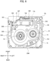
Fig. 9] Fig. 9A is a cross-sectional view taken along a line IXA-IXA inFig. 2C ,Fig. 9B is a cross-sectional view taken along a line IXB-IXB inFig. 2C ,Fig. 9B is a cross-sectional view taken along a line IXC-IXC inFig. 2C , andFig. 9D is a cross-sectional view taken along a line IXD-IXD inFig. 2C . - [
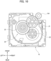
Fig. 10] Fig. 10 is a schematic view illustrating an engaging state between an output gear and a platen gear in the printing device ofFig. 1A . - A
printing device 1 illustrated inFig. 1A includes aprinting cassette 10 and aprinter body 100. Theprinting device 1 is configured to perform printing on aprinting tape 11A. - In the present embodiment, an axial direction of an
output gear 21 will be referred to as an up-down direction, a direction perpendicular to the up-down direction and coincident with a conveying direction of theprinting tape 11A at a discharge opening 33C will be referred to as a left-right direction, and a direction perpendicular to both of the up-down direction and the left-right direction will be referred to as a front-rear direction. - As illustrated in
Fig. 1B , theprinter body 100 includes acassette accommodating portion 101, aprinting head 102, aplaten roller 103, aplaten gear 104, adrive shaft 105, adrive source 107, and ahousing 110. - The
cassette accommodating portion 101 is a recessed portion to which theprinting cassette 10 is attachable. Thecassette accommodating portion 101 has a function to fix theprinting cassette 10 in position. Thecassette accommodating portion 101 is provided in thehousing 110. - The
cassette accommodating portion 101 includes a firstengaging portion 101A, a secondengaging portion 101B, and a thirdengaging portion 101C. The firstengaging portion 101A, the secondengaging portion 101B, and the thirdengaging portion 101C are configured to be engaged with acase 35 of theprinting cassette 10 inserted in thecassette accommodating portion 101. - The first
engaging portion 101A, the secondengaging portion 101B, and the thirdengaging portion 101C are respectively hooks extending in the up-down direction inside thecassette accommodating portion 101 and engageable with thecase 35 from the above. - The
printing head 102 is positioned inside thecassette accommodating portion 101. Theprinting head 102 includes a plurality of heat generating elements whose heat generation is configured to be controlled independently of each other. - The
platen roller 103 is positioned, inside thecassette accommodating portion 101, adjacent to theprinting head 102 so as to face theprinting head 102. Theplaten roller 103 is pivotally movable toward and away from theprinting head 102. Theplaten roller 103 has a rotation axis L1 that is parallel to the up-down direction. - The
platen gear 104 is connected to theplaten roller 103. In the present embodiment, theplaten gear 104 has a rotation axis L2 that is coincident with therotation axis L 1 of theplaten roller 103. Theplaten gear 104 is pivotally movable together with theplaten roller 103. - The
drive shaft 105 is configured to be inserted in a take-upspool 16 and aninput gear 22 of theprinting cassette 10. Thedrive shaft 105 is configured to input a driving force into theprinting cassette 10 to rotate the take-upspool 16 and theinput gear 22. - The
drive shaft 105 is positioned inside thecassette accommodating portion 101. Thedrive shaft 105 has a rotation axis L3 that is parallel to the up-down direction. Thedrive shaft 105 is rotatable about its rotation axis L3 by thedrive source 107. - The
drive source 107 is configured to drivingly rotate thedrive shaft 105. As thedrive source 107, a mechanism combining a motor and a gear is available, for example. - The
printing cassette 10 stores therein theprinting tape 11A. Theprinting cassette 10 is attachable to and detachable from theprinter body 100. By replacing theprinting cassette 10, replenishment of a printing medium and change of a kind (for example, size, color, and material, etc.) of the printing medium can be performed. - As illustrated in
Figs. 2A, 2B and 2C , theprinting cassette 10 includes thecase 35 that accommodates therein at least a part of theprinting tape 11A and at least a part of anink ribbon 14A (as an example of an auxiliary tape). - An outer shape of the printing cassette 10 (that is, the outer shape of the case 35) is a rectangular parallelepiped shape having sides parallel to the up-down direction, another sides parallel to the front-rear direction, and still another sides parallel to the left-right direction. The
case 35 can be inserted downward into thecassette accommodating portion 101. - As illustrated in
Fig. 3 , theprinting cassette 10 includes aprinting tape roll 11, afirst supply spool 12,spacer films auxiliary tape roll 14, asecond supply spool 15, the take-upspool 16, aclutch spring holder 17, and apower transmission mechanism 20. - The
printing tape roll 11 is configured by winding theprinting tape 11A over thefirst supply spool 12. On a surface of theprinting tape 11A, printing is performed by theprinting head 102 of theprinter body 100 and theink ribbon 14A. - The two
spacer films printing tape roll 11 such that thespacer films printing tape roll 11 therebetween. Thespacer film 13A is positioned between theprinting tape roll 11 and afirst cover part 31, and thespacer film 13B is positioned between theprinting tape roll 11 and afirst frame part 32. - The
first supply spool 12 is rotatable about its rotation axis L4 parallel to the up-down direction. Thefirst supply spool 12 is configured to rotate in accordance with conveyance of theprinting tape 11 by theplaten roller 103 of theprinter body 100, thereby supplying theprinting tape 11A to theprinting head 102. The rotation axis L4 of thefirst supply spool 12 is coincident with an axis of winding of theprinting tape roll 11. - The
auxiliary tape roll 14 is configured by winding theink ribbon 14A to be used for printing over thesecond supply spool 15. - The
ink ribbon 14A is superposed with theprinting tape 11A at ahead opening 33B, and is then to be used for printing by theprinting head 102. Theink ribbon 14A used for printing is then configured to be taken-up by the take-upspool 16. - To the
auxiliary tape roll 14, a rotational resistance is imparted by aclutch spring 17A held by theclutch spring holder 17. At least a part of theauxiliary tape roll 14 is positioned to overlap with theprinting tape roll 11 in the up-down direction. - The
second supply spool 15 is rotatable about its rotation axis L5. The rotation axis L5 of thesecond supply spool 15 is parallel to the up-down direction. Thesecond supply spool 15 is configured to rotate in accordance with taking up of theink ribbon 14A by the take-upspool 16, thereby supplying theink ribbon 14A to theprinting head 102. - The take-up
spool 16 is rotatable about its rotation axis L6. The rotation axis L6 of the take-upspool 16 is parallel to the rotation axis L5 of thesecond supply spool 15. - The take-up
spool 16 has a hollow cylindrical shape, and has an innerperipheral surface 16A that defines a hollow part. The innerperipheral surface 16A of the take-upspool 16 is formed withspline teeth 16B. To thespline teeth 16B, thedrive shaft 105 of theprinter body 100 is configured to be connected. The take-upspool 16 is configured to be rotated by thedrive shaft 105 to take up theink ribbon 14A. - The
power transmission mechanism 20 is configured to transmit the driving force of thedrive source 107 from thedrive shaft 105 to theplaten roller 103 upon attachment of theprinting cassette 10 to theprinter body 100. Thepower transmission mechanism 20 includes theoutput gear 21, theinput gear 22, and anidle gear 23. - As illustrated in
Fig. 4 , theprinting tape roll 11, thepower transmission mechanism 20, and the take-upspool 16 are arranged in the up-down direction in an order of theprinting tape roll 11, thepower transmission mechanism 20 and the take-upspool 16. - The
output gear 21 illustrated inFig. 3 is an externally toothed gear configured to output the driving force to an outside for conveying theprinting tape 11A. Specifically, theoutput gear 21 is configured to transmit the driving force to theplaten gear 104 of theprinter body 100. - The
output gear 21 has a rotation axis L7 that is parallel to the rotation axis L5 of thesecond supply spool 15. An entirety of theoutput gear 21 is overlapped with apartition wall 32B of thecase 35 in the up-down direction. Further, theoutput gear 21 has a part that is exposed to a space in communication with thehead opening 33B. - The
output gear 21 is configured to mesh with the platen gear 106 at the space in communication with thehead opening 33B upon attachment of theprinting cassette 10 to the printer body 100 (that is, upon accommodation of thecase 35 in the cassette accommodating portion 101). - The
input gear 22 indirectly meshes with theoutput gear 21 through theidle gear 23 to transmit the driving force to theoutput gear 21. - The
input gear 22 includes anexternal gear 22A, and aspool 22B which is a hollow cylindrical-shaped internal gear. Thespool 22B is fixed to a surface of theexternal gear 22A and has spline teeth at an inner peripheral surface of thespool 22B. Theexternal gear 22A is rotatable together with thespool 22B by the driving force of thedrive source 107 inputted in thespool 22B. - The
input gear 22 has a rotation axis L8 (that is, the rotation axes of theexternal gear 22A and thespool 22B) that is on the same line as the rotation axis L6 of the take-upspool 16. At least a part of theinput gear 22 is positioned to overlap with theprinting tape roll 11 in the up-down direction. - The rotation axis L8 of the
input gear 22 is overlapped with the hollow part of the take-upspool 16 in the up-down direction. Hence, thedrive shaft 105 penetrates through the take-upspool 16 and theinput gear 22 at the same time in a state where theprinting cassette 10 is attached to theprinter body 100. As a result, theinput gear 22 is rotatable together with the take-upspool 16 by thedrive shaft 105, even though theinput gear 22 is not directly connected to the take-upspool 16. - The
idle gear 23 is drivingly connected to theinput gear 22 and the output gear 21 (that is, the idle gearidle gear 23 is meshingly engaged with theinput gear 22 and the output gear 21) to transmit the driving force inputted in theinput gear 22 to theoutput gear 21. - The
idle gear 23 is a stepped gear configured of anupstream gear 23A, and adownstream gear 23B coaxially arranged with theupstream gear 23A. Theupstream gear 23A is in meshing engagement with theinput gear 22. Thedownstream gear 23B is in meshing engagement with theoutput gear 21. Thedownstream gear 23B has a smaller diameter than theupstream gear 23A. Further, thedownstream gear 23B is positioned closer to theprinting tape roll 11 in the up-down direction (i.e., above) than theupstream gear 23A is to theprinting tape roll 11 in the up-down direction. - The
idle gear 23 is configured to deceleratingly transmit the driving force inputted in theinput gear 22 to theoutput gear 21. That is, thepower transmission mechanism 20 includes a deceleration mechanism providing, as a reduction ratio, a transmission ratio obtained by dividing a rotation speed of theinput gear 22 by a rotation speed of theoutput gear 21. - The
case 35 includes thefirst cover part 31, thefirst frame part 32, asecond frame part 33, and asecond cover part 34. - The
first cover part 31 constitutes an upper end portion of theprinting cassette 10. Thefirst frame part 32 is positioned below thefirst cover part 31, and is connected to thefirst cover part 31 in the up-down direction. Thesecond frame part 33 is positioned below thefirst frame part 32, and is connected to thefirst frame part 32 in the up-down direction. Thesecond cover part 34 constitutes a lower end portion of theprinting cassette 10. Thesecond cover part 34 is connected to thesecond frame part 33 in the up-down direction. - The
first cover part 31 and thefirst frame part 32 constitute in combination aroll case 41 for accommodating theprinting tape roll 11 therein. That is, theprinting tape roll 11 is positioned in a space defined by thefirst cover part 31 and thefirst frame part 32. - The
second cover part 34 and thesecond frame part 33 constitute in combination aguide case 42 for accommodating therein theauxiliary tape roll 14, thesecond supply spool 15, and the take-upspool 16. That is, theauxiliary tape roll 14, thesecond supply spool 15, and the take-upspool 16 are positioned in a space defined by thesecond cover part 34 and thesecond frame part 33. Theguide case 42 is at a position different from the position of the printing tape roll 11 (specifically, below) in the up-down direction. - The
first frame part 32 and thesecond frame part 33 constitute in combination agear case 43 for accommodating therein a part of theoutput gear 21, theinput gear 22, and theidle gear 23. That is, the part of theoutput gear 21, theinput gear 22, and theidle gear 23 are positioned in a space defined by thefirst frame part 32 and thesecond frame part 33. Thegear case 43 is positioned between theroll case 41 and theguide case 42 in the up-down direction. - The
first frame part 32 includes afirst side wall 32A, thepartition wall 32B, and afirst guide 32C. Thefirst side wall 32A constitutes an outer side surface of thecase 35 that is parallel to the up-down direction. Thepartition wall 32B has a surface perpendicular to the up-down direction, and extends in the front-rear direction and in the left-right direction. Thepartition wall 32B is overlapped with theprinting tape roll 11 and thepower transmission mechanism 20 in the up-down direction. - As illustrated in
Fig. 5 , thefirst guide 32C is a portion along which theprinting tape 11A paid out from theprinting tape roll 11 is wound. Thefirst guide 32C includes a plurality of plate-like ribs arranged to be spaced away from one another in a circumferential direction of theprinting tape roll 11. The ribs protrude outward in a radial direction of theprinting tape roll 11 such that a protruding amount of each rib (that is, a plate width) gradually increases toward the bottom. - The
second frame part 33 illustrated inFig. 3 includes asecond side wall 33A, thehead opening 33B, thedischarge opening 33C, awall section 33D, anarm portion 33E, adischarge portion 33F, asecond guide 33G (an example of a guide portion),pawls Figs. 2A and 2B ), andabutment portions - In the
second frame part 33, at least thehead opening 33B, thewall section 33D, thearm portion 33E, thedischarge portion 33F, thesecond guide 33G, thepawls abutment portions guide case 42. - The
second side wall 33A constitutes an outer side surface of thecase 35 extending parallel to the up-down direction. Thehead opening 33B is a notched part of thesecond side wall 33A. Thehead opening 33B is a space in which theprinting head 102 is arranged in the state where theprinting cassette 10 is attached to theprinter body 100. - In the
head opening 33B, theprinting head 102 performs printing on theprinting tape 11A. Thehead opening 33B is open downward of theprinting cassette 10 so that theprinting head 102 can be inserted in thehead opening 33B from below. - As illustrated in
Fig. 6 , theprinting tape 11A and theink ribbon 14A are arranged to extend in the left-right direction at thehead opening 33B. Theprinting tape 11A is exposed to an outside of thecase 35 and is superposed with theink ribbon 14A at thehead opening 33B. After being printed, the printedprinting tape 11A is discharged to the outside of theprinting device 1 through thedischarge opening 33C. - The
wall section 33D illustrated inFig. 3 has a surface perpendicular to the up-down direction, and extends in the front-rear direction and the left-right direction. Thewall section 33D has a first shaft portion 33O rotatably supporting thesecond supply spool 15, and asecond shaft portion 33P rotatably supporting the take-upspool 16. - The
arm portion 33E is configured to convey theprinting tape 11A in the left-right direction at a position upstream of the head opening 33B and thedischarge opening 33C in a discharging direction of theprinting tape 11A. Thearm portion 33E constitutes a tunnel surrounding theprinting tape 11A in a widthwise direction thereof as well as in a thickness direction of theprinting tape 11A. - The
discharge portion 33F allows theprinting tape 11A, which has moved past thearm portion 33E, to be discharged to the outside (specifically, to the space in communication with thehead opening 33B). Thedischarge portion 33F constitutes an outlet of thearm portion 33E. Theprinting tape 11A discharged through thedischarge portion 33F is then conveyed to the discharge opening 33C through thehead opening 33B. - Similar to the
first guide 32C, thesecond guide 33G is a portion along which theprinting tape 11A paid out from theprinting tape roll 11 is wound. Thesecond guide 33G includes a plurality of plate-like ribs arranged to be spaced away from one another in a circumferential direction of theauxiliary tape roll 14. The ribs protrude outward in a radial direction of theauxiliary tape roll 14, and a protruding amount of each rib (i.e., a plate width) gradually decreases toward the bottom. - Each of the
first pawl 33H, the second pawl 33I, and thethird pawl 33J illustrated inFigs. 2A, 2B and 2C protrudes outward from thesecond side wall 33A of thesecond frame part 33. - The
first pawl 33H is positioned at afirst side surface 42A of theguide case 42. Thefirst side surface 42A is overlapped with thesecond guide 33G in a direction perpendicular to the center axis of the printing tape roll 11 (specifically, in the left-right direction). Thefirst side surface 42A is perpendicular to the left-right direction and constitutes a right side surface of theguide case 42. - The
first pawl 33H has afirst engagement surface 331 engageable with the first engagingportion 101A of theprinter body 100. Thefirst engagement surface 331 is constituted by a region of thefirst pawl 33H that is configured to contact the first engagingportion 101A to restrict upward movement of the guide case 42 (i.e., detachment from the cassette accommodating portion 101). - The
first engagement surface 331 extends to protrude outward (that is, rightward) of theguide case 42 from thefirst side surface 42A. Thefirst engagement surface 331 is a flat plane perpendicular to the up-down direction, and crosses thefirst side surface 42A. - The second pawl 33I and the
third pawl 33J are positioned at asecond side surface 42B of theguide case 42. Thesecond side surface 42B is overlapped with thesecond guide 33G in the direction perpendicular to the center axis of the printing tape roll 11 (specifically, in the left-right direction). - The
second side surface 42B is perpendicular to the left-right direction and constitutes a left side surface of theguide case 42. At least a part of thesecond side surface 42B (in the present embodiment, an entirety of thesecond side surface 42B) is at the same position as thefirst side surface 42A in the up-down direction. - The
first side surface 42A faces thesecond side surface 42B in the discharging direction of theprinting tape 11A at thedischarge portion 33F. Further, thefirst side surface 42A and thesecond side surface 42B are positioned to sandwich at least a part of thepower transmission mechanism 20 therebetween in the left-right direction. - The second pawl 33I has a
second engagement surface 332 engageable with the secondengaging portion 101B of theprinter body 100. Thethird pawl 33J has athird engagement surface 333 engageable with the thirdengaging portion 101C of theprinter body 100. Thesecond engagement surface 332 and thethird engagement surface 333 are constituted by regions of the second pawl 33I and thethird pawl 33J, respectively, the regions being configured to contact the secondengaging portion 101B and the thirdengaging portion 101C, respectively, to restrict upward movement of theguide case 42. - The
second engagement surface 332 and thethird engagement surface 333 extend respectively to protrude outward (that is, leftward) of theguide case 42 from thesecond side surface 42B. Thesecond engagement surface 332 and thethird engagement surface 333 are flat planes perpendicular to the up-down direction, and respectively cross thesecond side surface 42B. - The
first engagement surface 331, thesecond engagement surface 332, and thethird engagement surface 333 face in a direction (upward) which is opposite to an advancing direction of the guide case 42 (i.e., downward) at the time of insertion of theguide case 42 into thecassette accommodating portion 101. - That is, as illustrated in
Fig. 7 , thefirst engagement surface 331 is configured to be overlapped with a pawl of the first engagingportion 101A from above. Similarly, thesecond engagement surface 332 and thethird engagement surface 333 are configured to be overlapped with pawls of the secondengaging portion 101B and the thirdengaging portion 101C from above. Thefirst engagement surface 331, thesecond engagement surface 332 and thethird engagement surface 333 are respectively perpendicular to the advancing direction of theguide case 42 at the time of insertion of theguide case 42 into thecassette accommodating portion 101. - Incidentally, the first engaging
portion 101A, the secondengaging portion 101B, and the thirdengaging portion 101C are respectively movable in the left-right direction. Upon insertion of thecase 35 in thecassette accommodating portion 101, a locking state is provided for each engaging portion such that each engaging portion is engaged with each engagement surface. The locking state is released by moving each locking portion in a direction away from thecase 35. - As illustrated in
Fig. 4 , at least a part of the first engagement surface 331 (in the present embodiment, an entirety of the first engagement surface 331) is at the same position as thesecond engagement surface 332 in the up-down direction. Further, at least a part of the second engagement surface 332 (in the present embodiment, an entirety of the second engagement surface 332) is at the same position as thethird engagement surface 333. - The
printing tape roll 11, theoutput gear 21, thefirst engagement surface 331, and theauxiliary tape roll 14 are arranged in the up-down direction in such an order of theprinting tape roll 11, theoutput gear 21, thefirst engagement surface 331, and theauxiliary tape roll 14. - That is, the
auxiliary tape roll 14 is positioned opposite theprinting tape roll 11 and theoutput gear 21 with respect to thefirst engagement surface 331, thesecond engagement surface 332, and thethird engagement surface 333 in the up-down direction. - Further, at least a part of the
first engagement surface 331, at least a part of thesecond engagement surface 332, and at least a part of thethird engagement surface 333 are respectively at the same position as thewall section 33D in the up-down direction. In other words, thefirst engagement surface 331, thesecond engagement surface 332, and thethird engagement surface 333 are overlapped with thewall section 33D in the left-right direction. - As illustrated in
Fig. 8 , in theprinting cassette 10, a first imaginary straight line S1 is provided, the first imaginary straight line S1 passing through thefirst engagement surface 331 and thesecond engagement surface 332 and overlapping with theprinting tape roll 11 as viewed in the up-down direction. The first imaginary straight line S1 is also overlapped with theauxiliary tape roll 14 as viewed in the up-down direction. - Further, a second imaginary straight line S2 is provided in the
printing cassette 10, the second imaginary straight line S2 passing through a geometric centroid G1 of thefirst engagement surface 331 and a geometric centroid G2 of thesecond engagement surface 332 and overlapping with theprinting tape roll 11 as viewed in the up-down direction. - The
first abutment portion 33K, thesecond abutment portion 33L, and thethird abutment portion 33M respectively abut on theprinter body 100 in the up-down direction upon insertion of theguide case 42 in thecassette accommodating portion 101. - The
first abutment portion 33K, thesecond abutment portion 33L, and thethird abutment portion 33M are configured to make contact with corresponding portions of theprinter body 100 from above, thereby providing positioning of thecase 35 in the up-down direction relative to thecassette accommodating portion 101. - The
first abutment portion 33K, thesecond abutment portion 33L, and thethird abutment portion 33M are positioned to be spaced apart from one another. Further, when viewed in the up-down direction, a direction in which thefirst abutment portion 33K and thesecond abutment portion 33L are spaced apart from each other is different from a direction in which thesecond abutment portion 33L and thethird abutment portion 33M are spaced apart from each other. - That is, as viewed in the up-down direction, the
first abutment portion 33K, thesecond abutment portion 33L, and thethird abutment portion 33M are not arranged linearly. In other words, there is no imaginary straight line that can pass simultaneously through thefirst abutment portion 33K, thesecond abutment portion 33L, and thethird abutment portion 33M. - The
first abutment portion 33K is positioned to overlap with thehead opening 33B in the up-down direction. Specifically, thefirst abutment portion 33K is positioned above thehead opening 33B. Thefirst abutment portion 33K is exposed toward the bottom of theprinting cassette 10 through thehead opening 33B. Thefirst abutment portion 33K is configured to abut on theprinting head 102 that is inserted in thehead opening 33B. - The
second abutment portion 33L is positioned at a corner portion of thesecond frame part 33 as viewed in the up-down direction. Specifically, thesecond abutment portion 33L is constituted by a bottom surface of a hollow cylindrical body positioned at a left-front corner portion of thesecond frame part 33, the hollow cylindrical body having a center axis parallel to the up-down direction. - The
second abutment portion 33L is a bottom surface of a recessed portion which is a part of thesecond frame part 33 and which is recessed upward. Into the hollow cylindrical body constituting thesecond abutment portion 33L, a part extending in the up-down direction inside the cassette accommodating portion 101 (for example a pin) is configured to be inserted. - When viewed in the up-down direction, the bottom surface of the recessed portion constituting the
second abutment portion 33L extends in a direction perpendicular to the up-down direction. Specifically, the extending direction of the bottom surface of the recessed portion crosses both of the discharging direction of theprinting tape 11A at thedischarge opening 33C (that is, the left-right direction) and the front-rear direction. More specifically, the bottom surface of the recessed portion extends toward the rotation axis L8 of theinput gear 22, and the extending direction of the bottom surface of the recessed portion is perpendicular to a circumferential direction of a circle centered on the rotation axis L8 of theinput gear 22. - An inner peripheral surface of the hollow cylindrical body (that is, an inner side surface of the recessed portion) constituting the
second abutment portion 33L allows the pin inserted in the hollow cylindrical body to move in a direction crossing the left-right direction and the front-rear direction, but restricts the pin from pivotally moving about the rotation axis L8 of theinput gear 22. That is, the inner side surface of the recessed portion restricts thecase 35 from rotating about the rotation axis L3 of thedrive shaft 105. - The
third abutment portion 33M is arranged to be connected to an outer side surface of thesecond frame part 33 which is parallel to the up-down direction (specifically, a part of a rear side surface of the case 35). Thethird abutment portion 33M is constituted by a recessed portion formed in the rear side surface of thecase 35. - Further, the
third abutment portion 33M is at a position different from the position of the bottom surface of thecase 35 in the up-down direction (i.e., above the bottom surface). Thethird abutment portion 33M is configured to abut on an upper end of a part protruding in the up-down direction (for example, a rib) inside thecassette accommodating portion 101. - In the
printing cassette 10, an imaginary triangle T is provided as viewed in the up-down direction. The imaginary triangle T is defined by three vertexes positioned within thefirst abutment portion 33K, thesecond abutment portion 33L, and thethird abutment portion 33M, respectively. The imaginary triangle T is overlapped with the arbitrary first imaginary straight line S1. Further, the imaginary triangle T defines a center of gravity G3 that is positioned on the arbitrary first imaginary straight line S1 as viewed in the up-down direction. - As illustrated in
Figs. 9A, 9B, 9C and 9D , thefirst guide 32C and thesecond guide 33G define a pathway for conveying theprinting tape 11A constituting the printing tape roll 11 from theroll case 41 to theguide case 42. - Specifically, as illustrated in
Fig. 9A , theprinting tape 11A paid out from theprinting tape roll 11 is helically brought into contact with thefirst guide 32C from a radially outer side of theprinting tape roll 11, so that theprinting tape 11A is conveyed diagonally downward and rearward in theroll case 41. Theprinting tape 11A is further conveyed diagonally downward and leftward while straddling thegear case 43 in the up-down direction, as illustrated inFig. 9B . - The
printing tape 11A reaching theguide case 42 is brought into contact with thesecond guide 33G from a radially outer side thereof, so that theprinting tape 11A is conveyed diagonally downward and frontward, as illustrated inFig. 9C . Theprinting tape 11A reaching a lower end portion of theprinting cassette 10 passes through thehead opening 33B and is discharged rightward through thedischarge opening 33C, as illustrated inFig. 9D . - In the state where the
printing cassette 10 is attached to theprinter body 100, theprinting head 102 is positioned, at thehead opening 33B, to superpose with theprinting tape 11A and theink ribbon 14A in the front-rear direction. - The
printing tape 11A is conveyed to thehead opening 33B by theplaten roller 103, and is pressed by theplaten roller 103 through theink ribbon 14A against theprinting head 102 whose heat generating elements are heated. In this way, a part of ink on a surface of theink ribbon 14A is transferred to theprinting tape 11A, thereby printing letters and marks on theprinting tape 11A. - The
platen roller 103 conveys the printedprinting tape 11A toward the outside of theprinting cassette 10. Theplaten roller 103 is rotated by theplaten gear 104 engaged with theoutput gear 21. Theplaten roller 103 and theplaten gear 104 are pivotally movable between a position away from theprinting cassette 10 and a position illustrated inFig. 10 where theplaten gear 104 is engaged with theoutput gear 21. - In a state where the
case 35 of theprinting cassette 10 is accommodated in thecassette accommodating portion 101, thedrive shaft 105 is engaged with theinput gear 22, and theplaten gear 104 is engaged with theoutput gear 21. - Specifically, in a state where the
drive shaft 105 is inserted in the take-upspool 16 and theinput gear 22, theplaten roller 103 and theplaten gear 104 pivotally move toward thehead opening 33B of theprinting cassette 10 to bring theplaten gear 104 into engagement with theoutput gear 21. - In the state where the
printing cassette 10 is attached, thedrive shaft 105 rotates theinput gear 22 which in turn rotates theoutput gear 21. Further, the rotation of theoutput gear 21 rotates theplaten gear 104, thereby rotating theplaten roller 103. - The following technical advantages can be obtained according to the above-described embodiment.
- (1a) The
first engagement surface 331, thesecond engagement surface 332, and thethird engagement surface 333 are arranged to be offset from theprinting tape roll 11 in the axial direction of theprinting tape roll 11. With this structure, the arrangement of thefirst engagement surface 331, thesecond engagement surface 332, and thethird engagement surface 333 is less likely to hamper a degree of freedom in designing the size of theguide case 42. As a result, an increase in size of theprinting cassette 10 can be restrained. - (1b) Positional displacement of the
printing tape roll 11 relative to theprinter body 100 can be restrained, due to the existence of the first imaginary straight line S1 passing through thefirst engagement surface 331 and thesecond engagement surface 332 and overlapped with theprinting tape roll 11 as viewed in the up-down direction. - (1c) Due to the existence of the second imaginary straight line S2 passing through the geometric centroid G1 of the
first engagement surface 331 and the geometric centroid G2 of thesecond engagement surface 332 and overlapping with theprinting tape roll 11 as viewed in the up-down direction, an inhibitory effect against displacement of theprinting tape roll 11 relative to theprinter body 100 can further be promoted. - (1d) The inhibitory effect against displacement of the
auxiliary tape roll 14 relative to theprinter body 100 can further be promoted, since the first imaginary straight line S1 is overlapped with theauxiliary tape roll 14 as viewed in the up-down direction. - (1e) Enhanced accuracy in positioning of the
printing cassette 10 can be attained, due to the provision of the imaginary triangle T having three vertexes positioned respectively within thefirst abutment portion 33K, thesecond abutment portion 33L, and thethird abutment portion 33M, and overlapped with the first imaginary straight line S1. - (1f) The enhanced accuracy in positioning of the
printing cassette 10 can further be promoted, since the center of gravity G3 of the imaginary triangle T is overlapped with the first imaginary straight line S1 as viewed in the up-down direction. - (1g) Enhanced accuracy in positioning of the
printing cassette 10 can be obtained, since thefirst side surface 42A having thefirst engagement surface 331 faces thesecond side surface 42B having thesecond engagement surface 332 in the discharging direction of theprinting tape 11A at thedischarge portion 33F. - (1h) Since at least a part of the
first engagement surface 331 is at the same position as thesecond engagement surface 332 in the up-down direction, tilting of theprinting cassette 10 can be restrained. - (1i) Enhanced accuracy in positioning of the
printing cassette 10 can be achieved, since thethird engagement surface 333 is provided at thesecond side surface 42B. - (1j) The first
engaging portion 101A can have a simple configuration, since thefirst engagement surface 331 protrudes outward of theguide case 42 from thefirst side surface 42A. - (1k) Enhanced accuracy in positioning of the
printing tape roll 11 and theauxiliary tape roll 14 can be obtained, since thefirst engagement surface 331 is arranged between theprinting tape roll 11 and theauxiliary tape roll 14 in the up-down direction. - (1l) The engagement structure between the
guide case 42 and the first engagingportion 101A can be simplified, since thefirst engagement surface 331 faces upward. - (1m) Since the
first engagement surface 331 is the flat plane extending perpendicular to the up-down direction, the structure for engagement with the first engagingportion 101A can be simplified. - (1n) Since at least a part of the
first engagement surface 331 is at the same position as thewall section 33D in the up-down direction, the respective center axes of theauxiliary tape roll 14 and the take-upspool 16 are restrained from getting inclined. - While the embodiments according to the present disclosure have been described, it goes without saying that the present disclosure is not limited to the above-described embodiments and various configurations can be made thereto.
- (2a) The printing device according to the above-described embodiments need not be such a device using an ink ribbon for printing. For example, the printing device may perform printing on a strip-like heat sensitive paper. That is, the printing cassette does not necessarily include an ink ribbon.
Further, the printing device may use, as a printing tape, a stencil tape which is to be perforated to form a printing pattern by a thermal head. In a case that the stencil tape is employed as the printing tape, a lined paper tape is used as the auxiliary tape in place of the ink ribbon for protecting the stencil tape. - (2b) The printing cassette according to the above-described embodiments may not include a roll case. That is, the printing tape roll is not necessarily accommodated in the case.
- (2c) In the printing cassette according to the above-described embodiments, the guide case may not include the second engagement surface and the third engagement surface. Alternatively, the guide case may have four or more engagement surfaces.
- (2d) In the printing cassette according to the above-described embodiments, the power transmission mechanism may be positioned above the printing tape roll or below the first engagement surface. Alternatively, the printing cassette may not necessarily include the power transmission mechanism.
- (2e) The function(s) exhibited by a single component in the above-described embodiments may be exhibited by a plurality of components in a sharing manner, or the function(s) exhibited by a plurality of components in the above-described embodiments may be exhibited by a single component in an integrated manner. Further, the component in the above-described embodiments may be partly omitted. Still further, at least a part of the structure of the above-described embodiments may be added to or replaced with other configuration(s) of the embodiments. Incidentally, each and every aspect encompassed by the technological concept specified by the recitation of the claims are within the meaning of the embodiment of the present disclosure.
-
- 1 ... printing device, 10 ... printing cassette, 11 ... printing tape roll, 11A ... printing tape,
- 14 ... auxiliary tape roll, 14A ... ink ribbon, 16 ... take-up spool,
- 20 ... power transmission mechanism, 21 ... output gear, 22 ... input gear,
- 33 ... second frame part, 33B ... head opening, 33C ... discharge opening,
- 33D ... wall section, 33F ... discharge portion, 33G ... second guide,
- 33H ... first pawl, 33I ... second pawl, 33J ... third pawl, 33K ... first abutment portion,
- 33L ... second abutment portion, 33M ... third abutment portion, 35 ... case,
- 41 ... roll case, 42 ... guide case, 42A ... first side surface, 42B ... second side surface,
- 100 ... printer body, 101 ... cassette accommodating portion
- 101A ... first engaging portion, 101B ... second engaging portion, 101C ... third engaging portion, 331 ... first engagement surface, 332 ... second engagement surface, 333 ... third engagement surface
Claims (16)
- A printing cassette attachable to a printer body including a cassette accommodating portion provided with a first engaging portion, the printing cassette comprising:a printing tape roll configured of a printing tape; anda guide case arranged at a position different from a position of the printing tape roll in a first direction parallel to an axial direction of the printing tape roll, the guide case having:a guide portion configured to guide the printing tape paid out from the printing tape roll;a first side surface overlapped with the guide portion in a direction perpendicular to the first direction; anda first engagement surface engageable with the first engaging portion, the first engagement surface extending from the first side surface and crossing the first side surface.
- The printing cassette according to claim 1,wherein the cassette accommodating portion is further provided with a second engaging portion,wherein the guide case further has:a second side surface overlapped with the guide portion in the direction perpendicular to the first direction; anda second engagement surface engageable with the second engaging portion,wherein at least a part of the second side surface is at a position the same as a position of the first side surface in the first direction, andwherein the second engagement surface extends from the second side surface and crosses the second side surface.
- The printing cassette according to claim 2,
wherein a first imaginary straight line is provided, the first imaginary straight line passing through the first engagement surface and the second engagement surface and being overlapped with the printing tape roll as viewed in the first direction. - The printing cassette according to claim 3,
wherein a second imaginary straight line is provided, the second imaginary straight line passing through a geometric centroid of the first engagement surface and a geometric centroid of the second engagement surface and being overlapped with the printing tape roll as viewed in the first direction. - The printing cassette according to claim 3 or 4, further comprising an auxiliary tape roll configured of an auxiliary tape to be used for printing on the printing tape,wherein the auxiliary tape roll is accommodated in the guide case, andwherein the first imaginary straight line is overlapped with the auxiliary tape roll as viewed in the first direction.
- The printing cassette according to any one of claims 3 through 5,wherein the guide case further comprises a first abutment portion, a second abutment portion, and a third abutment portion each configured to abut on the printer body in the first direction in a state where the guide case is accommodated in the cassette accommodating portion,wherein the first abutment portion, the second abutment portion, and the third abutment portion are positioned to be spaced away from each other, andwherein an imaginary triangle is provided, the imaginary triangle being defined by three vertexes included respectively in the first abutment portion, the second abutment portion, and the third abutment portion and being overlapped with the first imaginary straight line as viewed in the first direction.
- The printing cassette according to claim 6,
wherein the imaginary triangle has a center of gravity that is overlapped with the first imaginary straight line as viewed in the first direction. - The printing cassette according to any one of claims 2 through 7,wherein the guide case further comprises a discharge portion through which the printing tape is to be discharged to an outside, andwherein the first side surface faces the second side surface in a discharging direction of the printing tape at the discharge portion.
- The printing cassette according to any one of claims 2 through 8,
wherein at least a part of the first engagement surface is at a position the same as the position of the second engagement surface in the first direction. - The printing cassette according to any one of claims 2 through 9,wherein the cassette accommodating portion is further provided with a third engaging portion,wherein the guide case further has a third engagement surface engageable with the third engaging portion, andwherein the third engagement surface extends from the second side surface and crosses the second side surface.
- The printing cassette according to any one of claims 1 through 10,
wherein the first engagement surface protrudes outward of the guide case from the first side surface. - The printing cassette according to any one of claims 1 through 11, further comprising an auxiliary tape roll configured of an auxiliary tape to be used for printing on the printing tape,wherein the auxiliary tape roll is accommodated in the guide case, andwherein the printing tape roll, the first engagement surface, and the auxiliary tape roll are arranged in the first direction in an order of the printing tape roll, the first engagement surface, and the auxiliary tape roll.
- The printing cassette according to any one of claims 1 through 12,
wherein the first engagement surface faces in a direction opposite a direction of insertion of the guide case into the cassette accommodating portion. - The printing cassette according to claim 13,
wherein the first engagement surface is a flat plane perpendicular to the direction of insertion. - The printing cassette according to any one of claims 1 through 14, further comprising:an auxiliary tape roll configured of an auxiliary tape to be used for printing on the printing tape; anda spool over which the auxiliary tape is to be wound,wherein the auxiliary tape roll and the spool are accommodated in the guide case,wherein the guide case comprises a wall section rotatably supporting the spool, andwherein at least a part of the first engagement surface is at a position the same as a position of the wall section in the first direction.
- A printing device comprising:a printer body comprising a cassette accommodating portion provided with a first engaging portion; andthe printing cassette according to any one of claims 1 through 15.
Applications Claiming Priority (2)
| Application Number | Priority Date | Filing Date | Title |
|---|---|---|---|
| JP2021050351A JP2022148606A (en) | 2021-03-24 | 2021-03-24 | Printing cassette and printing device |
| PCT/JP2022/011552 WO2022202481A1 (en) | 2021-03-24 | 2022-03-15 | Printing cassette and printing device |
Publications (2)
| Publication Number | Publication Date |
|---|---|
| EP4303024A1 true EP4303024A1 (en) | 2024-01-10 |
| EP4303024A4 EP4303024A4 (en) | 2025-02-26 |
Family
ID=83397220
Family Applications (1)
| Application Number | Title | Priority Date | Filing Date |
|---|---|---|---|
| EP22775271.4A Pending EP4303024A4 (en) | 2021-03-24 | 2022-03-15 | PRINTING CASSETTE AND PRINTING DEVICE |
Country Status (5)
| Country | Link |
|---|---|
| US (1) | US20240010014A1 (en) |
| EP (1) | EP4303024A4 (en) |
| JP (1) | JP2022148606A (en) |
| CN (1) | CN116997470A (en) |
| WO (1) | WO2022202481A1 (en) |
Families Citing this family (3)
| Publication number | Priority date | Publication date | Assignee | Title |
|---|---|---|---|---|
| JP7655034B2 (en) | 2021-03-24 | 2025-04-02 | ブラザー工業株式会社 | Printing cassette and printing device |
| JP1741067S (en) * | 2022-09-06 | 2023-04-06 | ||
| JP1742075S (en) * | 2022-09-06 | 2023-04-17 |
Family Cites Families (11)
| Publication number | Priority date | Publication date | Assignee | Title |
|---|---|---|---|---|
| GB0706786D0 (en) * | 2007-04-05 | 2007-05-16 | Dymo Nv | Label printer |
| JP4665973B2 (en) * | 2008-01-31 | 2011-04-06 | ブラザー工業株式会社 | Tape printer |
| JP4962520B2 (en) | 2009-03-31 | 2012-06-27 | ブラザー工業株式会社 | Tape cassette and tape printer |
| JP5234161B2 (en) * | 2011-11-10 | 2013-07-10 | ブラザー工業株式会社 | Tape cassette and tape printer |
| JP2016068407A (en) * | 2014-09-30 | 2016-05-09 | セイコーエプソン株式会社 | Tape cartridge |
| CN115447291B (en) * | 2018-03-29 | 2023-11-07 | 精工爱普生株式会社 | Ribbon cassettes and printing equipment |
| JP7342349B2 (en) * | 2018-09-21 | 2023-09-12 | ブラザー工業株式会社 | Cassette and cassette body |
| JP7309438B2 (en) * | 2018-12-26 | 2023-07-18 | セイコーエプソン株式会社 | cartridge |
| JP7272053B2 (en) * | 2019-03-28 | 2023-05-12 | セイコーエプソン株式会社 | tape printer |
| JP7192623B2 (en) * | 2019-03-31 | 2022-12-20 | ブラザー工業株式会社 | cassette |
| JP7272063B2 (en) * | 2019-03-31 | 2023-05-12 | ブラザー工業株式会社 | cassette |
-
2021
- 2021-03-24 JP JP2021050351A patent/JP2022148606A/en active Pending
-
2022
- 2022-03-15 CN CN202280022312.5A patent/CN116997470A/en active Pending
- 2022-03-15 WO PCT/JP2022/011552 patent/WO2022202481A1/en not_active Ceased
- 2022-03-15 EP EP22775271.4A patent/EP4303024A4/en active Pending
-
2023
- 2023-09-22 US US18/472,827 patent/US20240010014A1/en active Pending
Also Published As
| Publication number | Publication date |
|---|---|
| EP4303024A4 (en) | 2025-02-26 |
| CN116997470A (en) | 2023-11-03 |
| US20240010014A1 (en) | 2024-01-11 |
| JP2022148606A (en) | 2022-10-06 |
| WO2022202481A1 (en) | 2022-09-29 |
Similar Documents
| Publication | Publication Date | Title |
|---|---|---|
| US20240010014A1 (en) | Printing cassette including guide case having engagement surface protruding from side surface, and printing device using the same | |
| EP4019261B1 (en) | Printing device and printing cassette | |
| US12251929B2 (en) | Printing device capable of driving platen roller and cutter by a single motor | |
| EP4201687B1 (en) | Auxiliary tape cassette and printing tape cassette | |
| JP2025013535A (en) | Printing Cassette | |
| EP4265428A1 (en) | Auxiliary tape cassette, printing tape cassette, and printing cassette | |
| EP4205988B1 (en) | Auxiliary tape cassette | |
| EP4303022B1 (en) | Printing cassette and printing device | |
| EP4201688B1 (en) | Auxiliary tape cassette | |
| JP2024175134A (en) | Printing Cassette | |
| JP7528689B2 (en) | Printing cassette and printing device | |
| EP4603292A1 (en) | Printing cassette | |
| US20250236125A1 (en) | Printing cassette including helical gear as output gear configured to generate thrust load in axial direction thereof | |
| WO2022070985A1 (en) | Printing cassette | |
| CN119998133A (en) | Printing Box | |
| WO2021065473A1 (en) | Printing cassette | |
| WO2021065478A1 (en) | Printing device and printing cassette |
Legal Events
| Date | Code | Title | Description |
|---|---|---|---|
| STAA | Information on the status of an ep patent application or granted ep patent |
Free format text: STATUS: THE INTERNATIONAL PUBLICATION HAS BEEN MADE |
|
| PUAI | Public reference made under article 153(3) epc to a published international application that has entered the european phase |
Free format text: ORIGINAL CODE: 0009012 |
|
| STAA | Information on the status of an ep patent application or granted ep patent |
Free format text: STATUS: REQUEST FOR EXAMINATION WAS MADE |
|
| 17P | Request for examination filed |
Effective date: 20231002 |
|
| AK | Designated contracting states |
Kind code of ref document: A1 Designated state(s): AL AT BE BG CH CY CZ DE DK EE ES FI FR GB GR HR HU IE IS IT LI LT LU LV MC MK MT NL NO PL PT RO RS SE SI SK SM TR |
|
| P01 | Opt-out of the competence of the unified patent court (upc) registered |
Effective date: 20240131 |
|
| DAV | Request for validation of the european patent (deleted) | ||
| DAX | Request for extension of the european patent (deleted) | ||
| A4 | Supplementary search report drawn up and despatched |
Effective date: 20250128 |
|
| RIC1 | Information provided on ipc code assigned before grant |
Ipc: B41J 2/325 20060101ALI20250122BHEP Ipc: B65H 19/12 20060101ALI20250122BHEP Ipc: B41J 17/32 20060101AFI20250122BHEP |