EP4302974A2 - Container and method of manufacturing same - Google Patents
Container and method of manufacturing same Download PDFInfo
- Publication number
- EP4302974A2 EP4302974A2 EP23183357.5A EP23183357A EP4302974A2 EP 4302974 A2 EP4302974 A2 EP 4302974A2 EP 23183357 A EP23183357 A EP 23183357A EP 4302974 A2 EP4302974 A2 EP 4302974A2
- Authority
- EP
- European Patent Office
- Prior art keywords
- flow path
- container
- resin
- opening portion
- molten resin
- Prior art date
- Legal status (The legal status is an assumption and is not a legal conclusion. Google has not performed a legal analysis and makes no representation as to the accuracy of the status listed.)
- Pending
Links
Images






Classifications
-
- B—PERFORMING OPERATIONS; TRANSPORTING
- B41—PRINTING; LINING MACHINES; TYPEWRITERS; STAMPS
- B41J—TYPEWRITERS; SELECTIVE PRINTING MECHANISMS, i.e. MECHANISMS PRINTING OTHERWISE THAN FROM A FORME; CORRECTION OF TYPOGRAPHICAL ERRORS
- B41J2/00—Typewriters or selective printing mechanisms characterised by the printing or marking process for which they are designed
- B41J2/005—Typewriters or selective printing mechanisms characterised by the printing or marking process for which they are designed characterised by bringing liquid or particles selectively into contact with a printing material
- B41J2/01—Ink jet
- B41J2/17—Ink jet characterised by ink handling
- B41J2/175—Ink supply systems ; Circuit parts therefor
- B41J2/17503—Ink cartridges
- B41J2/1752—Mounting within the printer
- B41J2/17523—Ink connection
-
- B—PERFORMING OPERATIONS; TRANSPORTING
- B29—WORKING OF PLASTICS; WORKING OF SUBSTANCES IN A PLASTIC STATE IN GENERAL
- B29C—SHAPING OR JOINING OF PLASTICS; SHAPING OF MATERIAL IN A PLASTIC STATE, NOT OTHERWISE PROVIDED FOR; AFTER-TREATMENT OF THE SHAPED PRODUCTS, e.g. REPAIRING
- B29C33/00—Moulds or cores; Details thereof or accessories therefor
- B29C33/0055—Moulds or cores; Details thereof or accessories therefor with incorporated overflow cavities
-
- B—PERFORMING OPERATIONS; TRANSPORTING
- B29—WORKING OF PLASTICS; WORKING OF SUBSTANCES IN A PLASTIC STATE IN GENERAL
- B29C—SHAPING OR JOINING OF PLASTICS; SHAPING OF MATERIAL IN A PLASTIC STATE, NOT OTHERWISE PROVIDED FOR; AFTER-TREATMENT OF THE SHAPED PRODUCTS, e.g. REPAIRING
- B29C33/00—Moulds or cores; Details thereof or accessories therefor
- B29C33/10—Moulds or cores; Details thereof or accessories therefor with incorporated venting means
-
- B—PERFORMING OPERATIONS; TRANSPORTING
- B29—WORKING OF PLASTICS; WORKING OF SUBSTANCES IN A PLASTIC STATE IN GENERAL
- B29C—SHAPING OR JOINING OF PLASTICS; SHAPING OF MATERIAL IN A PLASTIC STATE, NOT OTHERWISE PROVIDED FOR; AFTER-TREATMENT OF THE SHAPED PRODUCTS, e.g. REPAIRING
- B29C45/00—Injection moulding, i.e. forcing the required volume of moulding material through a nozzle into a closed mould; Apparatus therefor
- B29C45/14—Injection moulding, i.e. forcing the required volume of moulding material through a nozzle into a closed mould; Apparatus therefor incorporating preformed parts or layers, e.g. injection moulding around inserts or for coating articles
- B29C45/14467—Joining articles or parts of a single article
-
- B—PERFORMING OPERATIONS; TRANSPORTING
- B29—WORKING OF PLASTICS; WORKING OF SUBSTANCES IN A PLASTIC STATE IN GENERAL
- B29C—SHAPING OR JOINING OF PLASTICS; SHAPING OF MATERIAL IN A PLASTIC STATE, NOT OTHERWISE PROVIDED FOR; AFTER-TREATMENT OF THE SHAPED PRODUCTS, e.g. REPAIRING
- B29C45/00—Injection moulding, i.e. forcing the required volume of moulding material through a nozzle into a closed mould; Apparatus therefor
- B29C45/17—Component parts, details or accessories; Auxiliary operations
- B29C45/26—Moulds
- B29C45/2669—Moulds with means for removing excess material, e.g. with overflow cavities
-
- B—PERFORMING OPERATIONS; TRANSPORTING
- B29—WORKING OF PLASTICS; WORKING OF SUBSTANCES IN A PLASTIC STATE IN GENERAL
- B29C—SHAPING OR JOINING OF PLASTICS; SHAPING OF MATERIAL IN A PLASTIC STATE, NOT OTHERWISE PROVIDED FOR; AFTER-TREATMENT OF THE SHAPED PRODUCTS, e.g. REPAIRING
- B29C45/00—Injection moulding, i.e. forcing the required volume of moulding material through a nozzle into a closed mould; Apparatus therefor
- B29C45/17—Component parts, details or accessories; Auxiliary operations
- B29C45/26—Moulds
- B29C45/34—Moulds having venting means
-
- B—PERFORMING OPERATIONS; TRANSPORTING
- B41—PRINTING; LINING MACHINES; TYPEWRITERS; STAMPS
- B41J—TYPEWRITERS; SELECTIVE PRINTING MECHANISMS, i.e. MECHANISMS PRINTING OTHERWISE THAN FROM A FORME; CORRECTION OF TYPOGRAPHICAL ERRORS
- B41J2/00—Typewriters or selective printing mechanisms characterised by the printing or marking process for which they are designed
- B41J2/005—Typewriters or selective printing mechanisms characterised by the printing or marking process for which they are designed characterised by bringing liquid or particles selectively into contact with a printing material
- B41J2/01—Ink jet
- B41J2/17—Ink jet characterised by ink handling
- B41J2/175—Ink supply systems ; Circuit parts therefor
- B41J2/17503—Ink cartridges
- B41J2/17513—Inner structure
-
- B—PERFORMING OPERATIONS; TRANSPORTING
- B41—PRINTING; LINING MACHINES; TYPEWRITERS; STAMPS
- B41J—TYPEWRITERS; SELECTIVE PRINTING MECHANISMS, i.e. MECHANISMS PRINTING OTHERWISE THAN FROM A FORME; CORRECTION OF TYPOGRAPHICAL ERRORS
- B41J2/00—Typewriters or selective printing mechanisms characterised by the printing or marking process for which they are designed
- B41J2/005—Typewriters or selective printing mechanisms characterised by the printing or marking process for which they are designed characterised by bringing liquid or particles selectively into contact with a printing material
- B41J2/01—Ink jet
- B41J2/17—Ink jet characterised by ink handling
- B41J2/175—Ink supply systems ; Circuit parts therefor
- B41J2/17503—Ink cartridges
- B41J2/17553—Outer structure
-
- B—PERFORMING OPERATIONS; TRANSPORTING
- B41—PRINTING; LINING MACHINES; TYPEWRITERS; STAMPS
- B41J—TYPEWRITERS; SELECTIVE PRINTING MECHANISMS, i.e. MECHANISMS PRINTING OTHERWISE THAN FROM A FORME; CORRECTION OF TYPOGRAPHICAL ERRORS
- B41J2/00—Typewriters or selective printing mechanisms characterised by the printing or marking process for which they are designed
- B41J2/005—Typewriters or selective printing mechanisms characterised by the printing or marking process for which they are designed characterised by bringing liquid or particles selectively into contact with a printing material
- B41J2/01—Ink jet
- B41J2/17—Ink jet characterised by ink handling
- B41J2/175—Ink supply systems ; Circuit parts therefor
- B41J2/17503—Ink cartridges
- B41J2/17559—Cartridge manufacturing
-
- B—PERFORMING OPERATIONS; TRANSPORTING
- B41—PRINTING; LINING MACHINES; TYPEWRITERS; STAMPS
- B41J—TYPEWRITERS; SELECTIVE PRINTING MECHANISMS, i.e. MECHANISMS PRINTING OTHERWISE THAN FROM A FORME; CORRECTION OF TYPOGRAPHICAL ERRORS
- B41J2/00—Typewriters or selective printing mechanisms characterised by the printing or marking process for which they are designed
- B41J2/005—Typewriters or selective printing mechanisms characterised by the printing or marking process for which they are designed characterised by bringing liquid or particles selectively into contact with a printing material
- B41J2/01—Ink jet
- B41J2/17—Ink jet characterised by ink handling
- B41J2/175—Ink supply systems ; Circuit parts therefor
- B41J2/17566—Ink level or ink residue control
-
- B—PERFORMING OPERATIONS; TRANSPORTING
- B29—WORKING OF PLASTICS; WORKING OF SUBSTANCES IN A PLASTIC STATE IN GENERAL
- B29C—SHAPING OR JOINING OF PLASTICS; SHAPING OF MATERIAL IN A PLASTIC STATE, NOT OTHERWISE PROVIDED FOR; AFTER-TREATMENT OF THE SHAPED PRODUCTS, e.g. REPAIRING
- B29C45/00—Injection moulding, i.e. forcing the required volume of moulding material through a nozzle into a closed mould; Apparatus therefor
- B29C45/0046—Details relating to the filling pattern or flow paths or flow characteristics of moulding material in the mould cavity
-
- B—PERFORMING OPERATIONS; TRANSPORTING
- B29—WORKING OF PLASTICS; WORKING OF SUBSTANCES IN A PLASTIC STATE IN GENERAL
- B29C—SHAPING OR JOINING OF PLASTICS; SHAPING OF MATERIAL IN A PLASTIC STATE, NOT OTHERWISE PROVIDED FOR; AFTER-TREATMENT OF THE SHAPED PRODUCTS, e.g. REPAIRING
- B29C45/00—Injection moulding, i.e. forcing the required volume of moulding material through a nozzle into a closed mould; Apparatus therefor
- B29C45/14—Injection moulding, i.e. forcing the required volume of moulding material through a nozzle into a closed mould; Apparatus therefor incorporating preformed parts or layers, e.g. injection moulding around inserts or for coating articles
- B29C45/14336—Coating a portion of the article, e.g. the edge of the article
-
- B—PERFORMING OPERATIONS; TRANSPORTING
- B29—WORKING OF PLASTICS; WORKING OF SUBSTANCES IN A PLASTIC STATE IN GENERAL
- B29L—INDEXING SCHEME ASSOCIATED WITH SUBCLASS B29C, RELATING TO PARTICULAR ARTICLES
- B29L2031/00—Other particular articles
- B29L2031/767—Printing equipment or accessories therefor
- B29L2031/7678—Ink or toner cartridges
-
- B—PERFORMING OPERATIONS; TRANSPORTING
- B41—PRINTING; LINING MACHINES; TYPEWRITERS; STAMPS
- B41J—TYPEWRITERS; SELECTIVE PRINTING MECHANISMS, i.e. MECHANISMS PRINTING OTHERWISE THAN FROM A FORME; CORRECTION OF TYPOGRAPHICAL ERRORS
- B41J2/00—Typewriters or selective printing mechanisms characterised by the printing or marking process for which they are designed
- B41J2/005—Typewriters or selective printing mechanisms characterised by the printing or marking process for which they are designed characterised by bringing liquid or particles selectively into contact with a printing material
- B41J2/01—Ink jet
- B41J2/17—Ink jet characterised by ink handling
- B41J2/175—Ink supply systems ; Circuit parts therefor
- B41J2/17566—Ink level or ink residue control
- B41J2002/17573—Ink level or ink residue control using optical means for ink level indication
Definitions
- the present invention relates to a container and a method of manufacturing the same.
- An inkjet recording head mounted on an inkjet recording apparatus includes an inkjet recording cartridge which stores liquid ink.
- Such an inkjet recording cartridge is manufactured conventionally by bonding a tank case and a lid which are molded members to each other by ultrasonic welding.
- a flow path plate is also bonded by supersonic welding.
- FIG. 15 is a schematic perspective view of a conventional liquid container 108, and shows a form in which a lid portion (first molded member 102) and a container portion (second molded member 103) are bonded to each other.
- FIG. 16 is a cross-sectional view of the liquid container 108 taken along the line A-A of FIG. 15 .
- a partition 111 is provided in a liquid storage portion 103a formed inside the second molded member 103 and, with this, a plurality of types of liquids (e.g., inks having a plurality of colors) can be separated and stored.
- a pair of protrusion portions 109 which are fitted on the partition 111 to prevent displacement at the time of coupling and spaces 110 (bonding grooves) into which molten resin 112 is injected are provided in fitting portions fitting to the second molded member 103.
- the second molded member 103 and the first molded member 102 can be bonded to each other with high accuracy by pouring the molten resin 112 into the spaces 110.
- the present invention has been made in view of the above problem, and the present invention is made to facilitate ascertaining a state of bonding resin when a plurality of members are bonded together with molten resin by using an in-mold assembly molding technique.
- the present invention in its first aspect provides a container as specified in claims 1 to 8.
- the present invention in its second aspect provides a cartridge as specified in claim 9.
- the present invention in its third aspect provides a method for manufacturing a container as specified in claim 10.
- the present invention it becomes possible to facilitate ascertaining the state of the bonding resin when the plurality of members are bonded together with the molten resin by using the in-mold assembly molding technique.
- the present invention is suitable for manufacturing of a molded article which uses an in-mold molding technique.
- in-mold molding a plurality of molded members are housed in a mold in a state in which the plurality of molded members are in contact with each other or fitted to each other, and the plurality of molded members are bonded together by pouring molten resin into a flow path such as a bonding groove.
- the molded article in the present invention can be especially preferably applied to, e.g., a liquid container including a lid portion and a container portion, and a manufacturing method thereof.
- An example of the liquid container includes an inkjet recording cartridge used in an inkjet recording head of an inkjet recording apparatus.
- FIG. 1 is a perspective view showing an example of the inkjet recording cartridge (hereinafter described as "cartridge 001").
- the cartridge 001 includes a first molded member 002, a second molded member 003, a third molded member 004, and an opening portion 005.
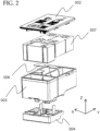
- FIG. 2 is an exploded perspective view of the cartridge 001.
- a filter 006 and an absorbing body 007 are incorporated into the first molded member 002, the second molded member 003, and the third molded member 004.
- the first molded member 002 is a lid of a container
- the second molded member 003 is a liquid storage tank.
- a chip is stuck to the third molded member 004, and the third molded member 004 functions as a component which discharges liquid.
- the present invention can be applied to any configuration in which at least two members are bonded to each other and a container is thereby formed.
- first member serving as the lid portion and a second member serving as the container portion are bonded to each other.
- the first member corresponds to the first molded member 002 in the embodiment
- the second member corresponds to the second molded member 003 in the embodiment.
- thermoplastic resin 012 it is desirable to use thermoplastic resin having fluidity higher than those of the first molded member 002, the second molded member 003, and the third molded member 004.
- a resin material is suitable, and the melting point of the resin material is preferably higher than that of the molten resin 012.
- the molten resin 012 and the material of each molded member are not limited thereto.
- FIG. 3 shows a configuration in which, when the first molded member 002, the second molded member 003, and the third molded member 004 are coupled and bonded together with the molten resin 012, the opening portion 005 which allows visual recognition of the state of the molten resin 012 is provided at an extension of a final filling portion 013.
- FIG. 3 is a side view showing the opening portion 005 which is provided at the extension of the final filling portion 013 and allows visual recognition of the state of the molten resin 012.
- the cartridge 001 shown in FIG. 3 there are cases where a liquid storage portion is separated into a plurality of liquid storage tanks, and there are cases where the liquid storage portion is constituted by one liquid storage tank.
- the cartridge 001 having the separation configuration is used for, e.g., a color cartridge, and different storage tanks are provided so as to correspond to liquids (inks) having different colors such as cyan (C), magenta (M), and yellow (Y) on a one-to-one basis. Individual storage layers are separated by partitions.
- the cartridge 001 having one liquid storage tank is used as a cartridge for one color such as, e.g., a cartridge for black (BK).
- FIG. 4A is a plan view showing a bonding surface of the third molded member 004 to the second molded member 003.
- the flow path 020 in FIG. 4A includes a lower flow path 020c, vertical communication flow paths 020b (one on the left and one on the right), and an opening portion communication flow path 020d. While dotted lines for indicating boundaries are drawn at boundaries between the lower flow path 020c, the vertical communication flow paths 020b, the opening portion communication flow path 020d, and the opening portion 005 for the sake of convenience, these flow paths and the opening portion actually communicate with each other. Note that terms "upper” and “lower” used in the present specification are used for the sake of convenience of explanation, and are not intended to define upper and lower sides when an actual container is disposed.
- FIG. 4B is a plan view showing a bonding surface of the second molded member 003 to the third molded member 004. Also in the second molded member 003, the flow path 020 in which the molten resin 012 flows is provided.
- the flow path 020 in FIG. 4B also includes the lower flow path 020c, the vertical communication flow paths 020b (one on the left and one on the right), and the opening portion communication flow path 020d.
- the dotted lines which indicate boundaries are drawn for the sake of convenience.
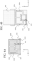
- FIG. 5A is a plan view showing a bonding surface of the first molded member 002 to the second molded member 003.
- the flow path 020 in which the molten resin 012 flows is provided.
- the flow path 020 in FIG. 5A includes an upper flow path 020a and the vertical communication flow paths 020b (one on the left and one on the right).
- a gate 021 serving as an inflow opening of the resin is provided out of both surfaces of the first molded member 002, on a surface (second surface) on the opposite side of the bonding surface (first surface) shown in the drawing.
- the gate 021 communicates with the upper flow path 020a through the inside of the first molded member 002.
- FIG. 5B is a plan view showing a bonding surface of the second molded member 003 to the first molded member 002. Also in the second molded member 003, the flow path 020 in which the molten resin 012 flows is provided.
- the flow path 020 in FIG. 5B also includes the upper flow path 020a and the vertical communication flow paths 020b (one on the left and one on the right).
- corresponding groove-shaped flow paths overlap each other to form a flow path hole through which the molten resin 012 flows.
- the vertical communication flow paths 020b function as the flow paths used when the molten resin 012 injected into the upper flow path 020a from the gate 021 flows into the lower flow path 020c.
- the configuration for the formation of the flow path is not limited thereto.
- a configuration may also be adopted in which a continuous groove is provided in one of the bonding surfaces, and a discontinuous groove is provided in the other one thereof.
- a configuration may also be adopted in which a groove is provided in one of the bonding surfaces and the groove is not provided in the other one thereof. It is possible to adopt any method which allows the formation of the flow path through which the molten resin 012 can pass when the bonding surfaces are bonded to each other.
- Step S1 processing of the present embodiment is started at a point of time when the individual molded members and members such as the filter and the absorbing body incorporated into the inside of the container are prepared.
- Step S2 the individual members are assembled, as shown in FIG. 2 .
- the assembled molded members are disposed inside a mold.
- the gate 021 is brought into a state in which the gate 021 can be accessed from the outside of the mold.
- the opening portion 005 is brought into a state in which the opening portion 005 faces an inner wall of the mold. With this, the molten resin 012 having reached the opening portion 005 is covered with the mold, and hence the molten resin 012 will not flow out to an exterior of the cartridge 001.
- Step S3 the molten resin 012 is injected from the gate 021, and the flow path 020 is thereby filled with the molten resin 012.
- the upper flow path 020a is filled with the molten resin 012 injected from the gate 021.
- the molten resin 012 reaches the lower flow path 020c via the vertical communication flow path 020b.
- the molten resin 012 reaches the final filling portion 013 after the lower flow path 020c is filled with the molten resin 012.
- the final filling portion 013 is a position in the flow path which allows a determination in which bonding is completed without any problem when filling with the resin is completed up to this position when the cartridge 001 is formed, and is a position serving as a target for reaching of the resin. That is, a term “final” does not deny that the resin having reached the final filling portion 013 further flows to the opening portion 005 positioned ahead of the final filling portion 013. Accordingly, "final filling portion” can be referred to as "filling target position".
- the molten resin 012 of the present embodiment reaches the opening portion 005 via the opening portion communication flow path 020d after reaching the final filling portion 013.
- Step S4 the molten resin 012 in the flow path is cured as time elapses.
- the first molded member 002, the second molded member 003, and the third molded member 004 are bonded together with the molten resin 012, and the cartridge 001 serving as the liquid container is formed.
- Step S5 by removing the mold and performing visual recognition of the opening portion 005, inspection of a product is performed.
- the opening portion 005 is an opening which is provided at the extension of the final filling portion 013 for visually recognizing the state of the molten resin 012 and is exposed to an outer wall of the cartridge 001.
- a user can inspect whether or not trouble such as leakage, overflowing, or shortage of the molten resin 012 is present by performing the visual recognition of the opening portion 005.
- "visual recognition" includes not only that the user performs checking by looking at the opening portion 005 but also that the user performs checking by taking a picture of the opening portion 005 with a camera and performing image processing.
- the amount of the molten resin 012 is set to an amount which allows not only the final filling portion 013 to be filled with the molten resin 012 but also the molten resin 012 to reach the opening portion 005.
- the opening portion 005 is filled with the cured molten resin 012
- the trouble is not present.
- the opening portion 005 is provided such that the state of the molten resin 012 can be visually recognized.
- FIG. 7A is a schematic perspective view showing a state in which the molten resin 012 is not present in the opening portion 005.
- FIG. 7B is a partially enlarged view of the opening portion 005. As shown in the drawings, the molten resin 012 does not reach the opening portion 005, and it is determined that the trouble such as leakage or overflowing has occurred.
- FIG. 8A is a schematic perspective view showing a state in which the molten resin 012 is present in the opening portion 005 in Embodiment 1.
- FIG. 8B is a partially enlarged view of the opening portion 005. As shown in the drawings, the opening portion 005 is filled with the molten resin 012, and hence it is determined that the trouble is not present.
- the opening portion 005 provided at the extension of the final filling portion 013. That is, when the opening portion 005 is blocked with the molten resin 012, it is possible to determine that the molten resin 012 reaches the final filling portion 013 definitely and bonding between the molded members is reliably performed. As a result, it becomes possible to facilitate grasping of the state of the molten resin 012 when a plurality of members are bonded together with the molten resin 012 by using an in-mold assembly molding technique. In addition, it is possible provide the inspection method which reliably detects the trouble such as leakage, overflowing, or shortage of the molten resin 012.
- FIGS. 9 to 11 are schematic views each showing a method of allowing visual recognition of molded article bonding in Embodiment 2.
- FIG. 9 is a plan view showing a bonding surface of the third molded member 004 to the second molded member 003, and shows a configuration in which a buffer portion 014 is provided at an extension of the opening portion 005.
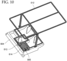
- FIG. 10 is a perspective view showing the bonding surface of the third molded member 004 to the second molded member 003, and shows a state at the time of bonding of the molten resin 012.
- FIG. 11 is a perspective view in which the vicinity of the buffer portion 014 in FIG. 7 is enlarged.
- FIG. 9 is a view showing the bonding surface of the third molded member 004 to the second molded member 003.
- a difference in configuration from Embodiment 1 is that the buffer portion 014 is provided at the extension of the opening portion 005.
- FIG. 10 shows a state when the molten resin 012 functions as a bonding member.
- FIG. 11 is a perspective view in which the vicinity of the buffer portion 014 in FIG. 10 is enlarged.
- a buffer portion communication flow path 020e and the buffer portion 014 are provided on the opposite side of the final filling portion 013 and the opening portion communication flow path 020d via the opening portion 005. It is possible to form the buffer portion communication flow path 020e and the buffer portion 014 by providing a groove or a concave portion in each molded member similarly to the other portions of the flow path.
- the buffer portion 014 functions as a part which absorbs a deviation of a filling amount of the molten resin 012 which bonds coupled molded members together. That is, the use of the buffer portion 014 is different from that of the flow path 020 which serves as a path into which the molten resin 012 is poured.
- the filling amount of the molten resin 012 is set to an amount which allows the molten resin 012 to reach at least the opening portion 005.
- the filling amount of the molten resin 012 there is a possibility that deviation may occur in the filling amount of the molten resin 012.
- deviation there are cases where deviation occurs also in the total volume of the flow path 020 due to manufacturing errors of individual molded parts.
- the filling amount of the molten resin 012 is set to an amount which allows the molten resin 012 to reach the opening portion 005. With this, even when the deviation occurs in the filling amount or the flow path total volume, it is possible to accurately perform product inspection.
- the filling amount is larger than the design value or the total volume of the flow path 020 is smaller than the design value, there is a possibility that the molten resin 012 may have no place to go after reaching the opening portion 005.
- the amount of the molten resin 012 is large for the flow path total volume, it is possible to absorb the molten resin 012 having flowed out beyond the opening portion 005 by providing the buffer portion 014 of the present embodiment.
- the buffer portion 014 at the extension portion of the opening portion 005 on the opposite side of the final filling portion 013, it is possible to absorb the deviation of the filling amount of the molten resin 012 while maintaining the effect of allowing the visual recognition of the state of the molten resin 012.
- FIG. 12 is a schematic plan view showing a method of allowing visual recognition of molded article bonding in Embodiment 3.
- the present embodiment is different from Embodiment 2 in that the buffer portion 014 is integrated with the opening portion 005. That is, the buffer portion communication flow path 020e is not provided, and the buffer portion 014 integrated with the opening portion 005 is formed.
- the buffer portion communication flow path 020e is not provided and the buffer portion 014 is integrated with the opening portion 005, the effect of storing the molten resin 012 caused to overflow by the deviation of the filling amount or the flow path total volume in the buffer portion 014 via the opening portion 005 is obtained.
- the configuration of the present embodiment it is not necessary to provide the buffer portion communication flow path 020e, and hence the configuration thereof is effective in the case where a molded member size or a molten resin amount is limited. Accordingly, it becomes possible to reduce a cartridge size and reduce the amount of the resin to be used.
- FIG. 13 and FIGS. 14A to 14D are schematic views each showing a method of allowing visual recognition of molded article bonding in Embodiment 4.
- FIG. 13 shows a schematic perspective view of an entire molded article and a direction of each visual field.
- FIGS. 14A to 14D show schematic side views from the individual visual fields.
- the opening portion 005 which allows visual recognition of the state of the molten resin 012 is provided at the extension of the final filling portion 013.
- a plurality of intermediate opening portions 015a to 015g which allow visual recognition of a state of bonding of the molten resin 012 being in progress are provided.
- Each of the intermediate opening portions 015a, 015c, 015e, and 015f is formed so as to branch from the upper flow path 020a and be exposed to the exterior of the cartridge 001. It is possible to inspect the state of bonding with the molten resin 012 being in progress between the first molded member 002 and the second molded member 003 by performing the visual recognition of the intermediate opening portions 015a, 015c, 015e, and 015f.
- Each of the intermediate opening portions 015b, 015d, and 015g is formed so as to branch from the lower flow path 020c and be exposed to the exterior of the cartridge 001. It is possible to inspect the state of bonding with the molten resin 012 being in progress between the second molded member 003 and the third molded member 004 by performing the visual recognition of the intermediate opening portions 015b, 015d, and 015g.
- a container which includes a first member which serves as a lid portion, a second member which serves as a container portion, and resin with which a flow path, which is formed between the first member and the second member when the first member and the second member come into contact with each other, is filled, the resin bonds the first member and the second member to each other by reaching a filling target position after flowing in from an inflow opening to the flow path, and an opening portion exposed to an exterior of the container is provided at a position where the resin having flowed in from the inflow opening flows out beyond the filling target position in the flow path.
Landscapes
- Engineering & Computer Science (AREA)
- Manufacturing & Machinery (AREA)
- Mechanical Engineering (AREA)
- Injection Moulding Of Plastics Or The Like (AREA)
- Moulds For Moulding Plastics Or The Like (AREA)
- Ink Jet (AREA)
- Rigid Containers With Two Or More Constituent Elements (AREA)
- Tubes (AREA)
- Containers And Packaging Bodies Having A Special Means To Remove Contents (AREA)
Abstract
Description
- The present invention relates to a container and a method of manufacturing the same.
- An inkjet recording head mounted on an inkjet recording apparatus includes an inkjet recording cartridge which stores liquid ink. Such an inkjet recording cartridge is manufactured conventionally by bonding a tank case and a lid which are molded members to each other by ultrasonic welding. In addition, in a multi-color inkjet recording cartridge, a flow path plate is also bonded by supersonic welding. In recent years, there is proposed a method in which, when the inkjet recording head or the inkjet recording cartridge is manufactured, molded members are coupled to each other and are bonded together with molten resin by using an in-mold assembly molding technique.
-
Japanese Patent Application Publication No. 2019-051597 FIG. 15 is a schematic perspective view of a conventionalliquid container 108, and shows a form in which a lid portion (first molded member 102) and a container portion (second molded member 103) are bonded to each other. -
FIG. 16 is a cross-sectional view of theliquid container 108 taken along the line A-A ofFIG. 15 . Apartition 111 is provided in aliquid storage portion 103a formed inside the second moldedmember 103 and, with this, a plurality of types of liquids (e.g., inks having a plurality of colors) can be separated and stored. In the first moldedmember 102, a pair ofprotrusion portions 109 which are fitted on thepartition 111 to prevent displacement at the time of coupling and spaces 110 (bonding grooves) into whichmolten resin 112 is injected are provided in fitting portions fitting to the second moldedmember 103. The second moldedmember 103 and the first moldedmember 102 can be bonded to each other with high accuracy by pouring themolten resin 112 into thespaces 110. - Herein, in a case where the molten resin is poured for coupling two molded members such as the container portion and the lid portion to each other, there is a possibility that trouble (e.g., leakage, overflowing, or shortage) of bonding resin may occur. In addition, in the technique of
Japanese Patent Application Publication No. 2019-051597 - The present invention has been made in view of the above problem, and the present invention is made to facilitate ascertaining a state of bonding resin when a plurality of members are bonded together with molten resin by using an in-mold assembly molding technique.
- The present invention in its first aspect provides a container as specified in
claims 1 to 8. - The present invention in its second aspect provides a cartridge as specified in claim 9.
- The present invention in its third aspect provides a method for manufacturing a container as specified in claim 10.
- According to the present invention, it becomes possible to facilitate ascertaining the state of the bonding resin when the plurality of members are bonded together with the molten resin by using the in-mold assembly molding technique.
- Further features of the present invention will become apparent from the following description of exemplary embodiments with reference to the attached drawings.
-
-
FIG. 1 is a schematic perspective view of an inkjet recording cartridge; -
FIG. 2 is an exploded perspective view of the inkjet recording cartridge; -
FIG. 3 is a side view showing an opening portion in Embodiment 1; -
FIGS. 4A and 4B are exploded plan views each showing the opening portion inEmbodiment 1; -
FIGS. 5A and 5B are exploded plan views each showing a flow path into which molten resin flows inEmbodiment 1; -
FIG. 6 is a flowchart showing processes of manufacturing and inspection of a liquid container; -
FIGS. 7A and 7B are schematic views each showing a state in which the molten resin is not present in the opening portion inEmbodiment 1; -
FIGS. 8A and 8B are schematic views each showing a state in which the molten resin is present in the opening portion inEmbodiment 1; -
FIG. 9 is a plan view showing a bonding surface of a third molded member to a second molded member in Embodiment 2; -
FIG. 10 is a perspective view showing a state at the time of bonding of the molten resin in Embodiment 2; -
FIG. 11 is an enlarged perspective view of the vicinity of a buffer portion in Embodiment 2; -
FIG. 12 is a schematic plan view showing a method of allowing visual recognition of molded article bonding in Embodiment 3; -
FIG. 13 is a schematic perspective view showing a direction of a visual field to a molded article in Embodiment 4; -
FIGS. 14A to 14D are schematic side views from the individual visual fields of the molded article; -
FIG. 15 is a schematic perspective view of a conventional liquid container; and -
FIG. 16 is a cross-sectional view of the conventional liquid container. - Hereinbelow, preferred embodiments of the present invention will be illustratively described in detail with reference to the drawings. Note that the dimensions, materials, shapes, and relative arrangements of components described in the following embodiments should be appropriately changed according to the configuration and various conditions of an apparatus to which the present invention is applied. Accordingly, unless otherwise specified expressly, it is not intended to limit the scope of the present invention to the dimensions, materials, shapes, and relative arrangements thereof.
- The present invention is suitable for manufacturing of a molded article which uses an in-mold molding technique. In in-mold molding, a plurality of molded members are housed in a mold in a state in which the plurality of molded members are in contact with each other or fitted to each other, and the plurality of molded members are bonded together by pouring molten resin into a flow path such as a bonding groove. The molded article in the present invention can be especially preferably applied to, e.g., a liquid container including a lid portion and a container portion, and a manufacturing method thereof. An example of the liquid container includes an inkjet recording cartridge used in an inkjet recording head of an inkjet recording apparatus.
-
FIG. 1 is a perspective view showing an example of the inkjet recording cartridge (hereinafter described as "cartridge 001"). Thecartridge 001 includes a first moldedmember 002, a second moldedmember 003, a third moldedmember 004, and anopening portion 005. -
FIG. 2 is an exploded perspective view of thecartridge 001. Afilter 006 and an absorbingbody 007 are incorporated into the first moldedmember 002, the second moldedmember 003, and the third moldedmember 004. In the present embodiment, the first moldedmember 002 is a lid of a container, and the second moldedmember 003 is a liquid storage tank. A chip is stuck to the third moldedmember 004, and the third moldedmember 004 functions as a component which discharges liquid. Note that the present invention can be applied to any configuration in which at least two members are bonded to each other and a container is thereby formed. In the case where a liquid container is manufactured, at least a first member serving as the lid portion and a second member serving as the container portion are bonded to each other. The first member corresponds to the first moldedmember 002 in the embodiment, and the second member corresponds to the second moldedmember 003 in the embodiment. - With regard to
molten resin 012, it is desirable to use thermoplastic resin having fluidity higher than those of the first moldedmember 002, the second moldedmember 003, and the third moldedmember 004. As each of the first moldedmember 002, the second moldedmember 003, and the third moldedmember 004, a resin material is suitable, and the melting point of the resin material is preferably higher than that of themolten resin 012. Note that themolten resin 012 and the material of each molded member are not limited thereto. - Each of
FIG. 3 ,FIGS. 4A and 4B , andFIGS. 5A and 5B is a schematic view showing a method of allowing visual recognition of molded article bonding inEmbodiment 1.FIG. 3 shows a configuration in which, when the first moldedmember 002, the second moldedmember 003, and the third moldedmember 004 are coupled and bonded together with themolten resin 012, theopening portion 005 which allows visual recognition of the state of themolten resin 012 is provided at an extension of afinal filling portion 013.FIG. 3 is a side view showing theopening portion 005 which is provided at the extension of thefinal filling portion 013 and allows visual recognition of the state of themolten resin 012. - In the
cartridge 001 shown inFIG. 3 , there are cases where a liquid storage portion is separated into a plurality of liquid storage tanks, and there are cases where the liquid storage portion is constituted by one liquid storage tank. Thecartridge 001 having the separation configuration is used for, e.g., a color cartridge, and different storage tanks are provided so as to correspond to liquids (inks) having different colors such as cyan (C), magenta (M), and yellow (Y) on a one-to-one basis. Individual storage layers are separated by partitions. In addition, thecartridge 001 having one liquid storage tank is used as a cartridge for one color such as, e.g., a cartridge for black (BK). -
FIG. 4A is a plan view showing a bonding surface of the third moldedmember 004 to the second moldedmember 003. In the third moldedmember 004, a flow path 020 in which themolten resin 012 flows is provided. The flow path 020 inFIG. 4A includes alower flow path 020c, verticalcommunication flow paths 020b (one on the left and one on the right), and an opening portioncommunication flow path 020d. While dotted lines for indicating boundaries are drawn at boundaries between thelower flow path 020c, the verticalcommunication flow paths 020b, the opening portioncommunication flow path 020d, and theopening portion 005 for the sake of convenience, these flow paths and the opening portion actually communicate with each other. Note that terms "upper" and "lower" used in the present specification are used for the sake of convenience of explanation, and are not intended to define upper and lower sides when an actual container is disposed. -
FIG. 4B is a plan view showing a bonding surface of the second moldedmember 003 to the third moldedmember 004. Also in the second moldedmember 003, the flow path 020 in which themolten resin 012 flows is provided. The flow path 020 inFIG. 4B also includes thelower flow path 020c, the verticalcommunication flow paths 020b (one on the left and one on the right), and the opening portioncommunication flow path 020d. Similarly, the dotted lines which indicate boundaries are drawn for the sake of convenience. When the second moldedmember 003 and the third moldedmember 004 come into contact with each other, corresponding groove-shaped flow paths overlap each other to form a flow path hole through which themolten resin 012 flows. -
FIG. 5A is a plan view showing a bonding surface of the first moldedmember 002 to the second moldedmember 003. In the first moldedmember 002, the flow path 020 in which themolten resin 012 flows is provided. The flow path 020 inFIG. 5A includes anupper flow path 020a and the verticalcommunication flow paths 020b (one on the left and one on the right). In addition, out of both surfaces of the first moldedmember 002, on a surface (second surface) on the opposite side of the bonding surface (first surface) shown in the drawing, agate 021 serving as an inflow opening of the resin is provided. As shown in the drawing, thegate 021 communicates with theupper flow path 020a through the inside of the first moldedmember 002. -
FIG. 5B is a plan view showing a bonding surface of the second moldedmember 003 to the first moldedmember 002. Also in the second moldedmember 003, the flow path 020 in which themolten resin 012 flows is provided. The flow path 020 inFIG. 5B also includes theupper flow path 020a and the verticalcommunication flow paths 020b (one on the left and one on the right). When the first moldedmember 002 and the second moldedmember 003 come into contact with each other, corresponding groove-shaped flow paths overlap each other to form a flow path hole through which themolten resin 012 flows. In addition, when the first moldedmember 002, the second moldedmember 003, and the third moldedmember 004 are bonded together and are disposed in a mold, the verticalcommunication flow paths 020b function as the flow paths used when themolten resin 012 injected into theupper flow path 020a from thegate 021 flows into thelower flow path 020c. - In the present embodiment, in order to form the flow path, similar grooves are formed in both of two bonding surfaces which come into contact with each other.
- With this, bonding having high strength is allowed. However, the configuration for the formation of the flow path is not limited thereto. For example, a configuration may also be adopted in which a continuous groove is provided in one of the bonding surfaces, and a discontinuous groove is provided in the other one thereof. In addition, for example, a configuration may also be adopted in which a groove is provided in one of the bonding surfaces and the groove is not provided in the other one thereof. It is possible to adopt any method which allows the formation of the flow path through which the
molten resin 012 can pass when the bonding surfaces are bonded to each other. - A description will be given of processes of a method of manufacturing the
cartridge 001 including the liquid storage tank as in the present embodiment, and an inspection method. - In a flowchart in
FIG. 6 , processing of the present embodiment is started at a point of time when the individual molded members and members such as the filter and the absorbing body incorporated into the inside of the container are prepared. In Step S1, the individual members are assembled, as shown inFIG. 2 . At this point, it is preferable that fitting portions provided in the individual molded members are fitted to each other. Next, in Step S2, the assembled molded members are disposed inside a mold. At this point, thegate 021 is brought into a state in which thegate 021 can be accessed from the outside of the mold. In addition, theopening portion 005 is brought into a state in which theopening portion 005 faces an inner wall of the mold. With this, themolten resin 012 having reached theopening portion 005 is covered with the mold, and hence themolten resin 012 will not flow out to an exterior of thecartridge 001. - Next, in Step S3, the
molten resin 012 is injected from thegate 021, and the flow path 020 is thereby filled with themolten resin 012. Specifically, first, theupper flow path 020a is filled with themolten resin 012 injected from thegate 021. Subsequently, themolten resin 012 reaches thelower flow path 020c via the verticalcommunication flow path 020b. Then, themolten resin 012 reaches thefinal filling portion 013 after thelower flow path 020c is filled with themolten resin 012. Note that thefinal filling portion 013 is a position in the flow path which allows a determination in which bonding is completed without any problem when filling with the resin is completed up to this position when thecartridge 001 is formed, and is a position serving as a target for reaching of the resin. That is, a term "final" does not deny that the resin having reached thefinal filling portion 013 further flows to theopening portion 005 positioned ahead of thefinal filling portion 013. Accordingly, "final filling portion" can be referred to as "filling target position". In addition, although described later in detail, themolten resin 012 of the present embodiment reaches theopening portion 005 via the opening portioncommunication flow path 020d after reaching thefinal filling portion 013. - Next, in Step S4, the
molten resin 012 in the flow path is cured as time elapses. With this, the first moldedmember 002, the second moldedmember 003, and the third moldedmember 004 are bonded together with themolten resin 012, and thecartridge 001 serving as the liquid container is formed. Next, in Step S5, by removing the mold and performing visual recognition of theopening portion 005, inspection of a product is performed. - Then, a description will be given of an inspection method which uses the
opening portion 005. As shown inFIG. 3 andFIGS. 4A and 4B , theopening portion 005 is an opening which is provided at the extension of thefinal filling portion 013 for visually recognizing the state of themolten resin 012 and is exposed to an outer wall of thecartridge 001. A user can inspect whether or not trouble such as leakage, overflowing, or shortage of themolten resin 012 is present by performing the visual recognition of theopening portion 005. Note that "visual recognition" includes not only that the user performs checking by looking at theopening portion 005 but also that the user performs checking by taking a picture of theopening portion 005 with a camera and performing image processing. - A description will be given of the inspection by the visual recognition by using
FIGS. 7A and 7B andFIGS. 8A and 8B . Herein, in the present embodiment, the amount of themolten resin 012 is set to an amount which allows not only thefinal filling portion 013 to be filled with themolten resin 012 but also themolten resin 012 to reach theopening portion 005. In addition, it is determined whether or not the flow path is filled with the resin up to theopening portion 005 when the mold is removed. Subsequently, in the case where themolten resin 012 does not reach theopening portion 005, it is determined that there is a possibility that the trouble such as leakage, overflowing, or shortage of themolten resin 012 may be present. On the other hand, in the case where theopening portion 005 is filled with the curedmolten resin 012, it is determined that the trouble is not present. - Note that, in the case where only a part of the
opening portion 005 is filled with themolten resin 012 and the remaining part does not have themolten resin 012, it is determined that the trouble is present in general. However, depending on the configuration of the opening portioncommunication flow path 020d or theopening portion 005, there are cases where it is determined that the product has passed the inspection based on reaching of themolten resin 012 to theopening portion 005. - Conventionally, it is possible to identify the leakage or overflowing of the
molten resin 012 in an outer appearance portion of thecartridge 001 after molding is completed by visual inspection or the like, but there is no means for identifying the leakage or overflowing in the case where the leakage or overflowing is present inside thecartridge 001. To cope with this, in the present embodiment, theopening portion 005 is provided such that the state of themolten resin 012 can be visually recognized. - The inspection method will be described more specifically by using
FIGS. 7A and 7B andFIGS. 8A and 8B .FIG. 7A is a schematic perspective view showing a state in which themolten resin 012 is not present in theopening portion 005.FIG. 7B is a partially enlarged view of theopening portion 005. As shown in the drawings, themolten resin 012 does not reach theopening portion 005, and it is determined that the trouble such as leakage or overflowing has occurred. -
FIG. 8A is a schematic perspective view showing a state in which themolten resin 012 is present in theopening portion 005 inEmbodiment 1.FIG. 8B is a partially enlarged view of theopening portion 005. As shown in the drawings, theopening portion 005 is filled with themolten resin 012, and hence it is determined that the trouble is not present. - According to the above configuration, it is possible to determine the state of the
molten resin 012 by using theopening portion 005 provided at the extension of thefinal filling portion 013. That is, when theopening portion 005 is blocked with themolten resin 012, it is possible to determine that themolten resin 012 reaches thefinal filling portion 013 definitely and bonding between the molded members is reliably performed. As a result, it becomes possible to facilitate grasping of the state of themolten resin 012 when a plurality of members are bonded together with themolten resin 012 by using an in-mold assembly molding technique. In addition, it is possible provide the inspection method which reliably detects the trouble such as leakage, overflowing, or shortage of themolten resin 012. - Then, Embodiment 2 will be described with reference to the drawings. The same components as those in the above embodiment are designated by the same reference numerals, and the description thereof will be simplified.
-
FIGS. 9 to 11 are schematic views each showing a method of allowing visual recognition of molded article bonding in Embodiment 2.FIG. 9 is a plan view showing a bonding surface of the third moldedmember 004 to the second moldedmember 003, and shows a configuration in which abuffer portion 014 is provided at an extension of theopening portion 005.FIG. 10 is a perspective view showing the bonding surface of the third moldedmember 004 to the second moldedmember 003, and shows a state at the time of bonding of themolten resin 012.FIG. 11 is a perspective view in which the vicinity of thebuffer portion 014 inFIG. 7 is enlarged. -
FIG. 9 is a view showing the bonding surface of the third moldedmember 004 to the second moldedmember 003. A difference in configuration fromEmbodiment 1 is that thebuffer portion 014 is provided at the extension of theopening portion 005. - In the configuration of the present embodiment, when the
molten resin 012 having flowed in from thegate 021 is cured, themolten resin 012 is formed into a shape shown inFIG. 10 in the liquid container. That is,FIG. 10 shows a state when themolten resin 012 functions as a bonding member. -
FIG. 11 is a perspective view in which the vicinity of thebuffer portion 014 inFIG. 10 is enlarged. As shown inFIGS. 9 and11 , a buffer portioncommunication flow path 020e and thebuffer portion 014 are provided on the opposite side of thefinal filling portion 013 and the opening portioncommunication flow path 020d via theopening portion 005. It is possible to form the buffer portioncommunication flow path 020e and thebuffer portion 014 by providing a groove or a concave portion in each molded member similarly to the other portions of the flow path. - The
buffer portion 014 functions as a part which absorbs a deviation of a filling amount of themolten resin 012 which bonds coupled molded members together. That is, the use of thebuffer portion 014 is different from that of the flow path 020 which serves as a path into which themolten resin 012 is poured. - Herein, in the configuration of
Embodiment 1, the filling amount of themolten resin 012 is set to an amount which allows themolten resin 012 to reach at least theopening portion 005. However, there is a possibility that deviation may occur in the filling amount of themolten resin 012. In addition, there are cases where deviation occurs also in the total volume of the flow path 020 due to manufacturing errors of individual molded parts. - In the case where the filling amount is smaller than a design value or the total volume of the flow path 020 is larger than a design value, there is a possibility that the
molten resin 012 may not reach theopening portion 005. To cope with this, based on the assumption that the deviation occurs, the filling amount of themolten resin 012 is set to an amount which allows themolten resin 012 to reach theopening portion 005. With this, even when the deviation occurs in the filling amount or the flow path total volume, it is possible to accurately perform product inspection. - On the other hand, in the case where the filling amount is larger than the design value or the total volume of the flow path 020 is smaller than the design value, there is a possibility that the
molten resin 012 may have no place to go after reaching theopening portion 005. Thus, even in the case where the amount of themolten resin 012 is large for the flow path total volume, it is possible to absorb themolten resin 012 having flowed out beyond the openingportion 005 by providing thebuffer portion 014 of the present embodiment. - Thus, by providing the
buffer portion 014 at the extension portion of theopening portion 005 on the opposite side of thefinal filling portion 013, it is possible to absorb the deviation of the filling amount of themolten resin 012 while maintaining the effect of allowing the visual recognition of the state of themolten resin 012. - Then, Embodiment 3 will be described with reference to the drawings. The same components as those in the above embodiments are designated by the same reference numerals, and the description thereof will be simplified.
-
FIG. 12 is a schematic plan view showing a method of allowing visual recognition of molded article bonding in Embodiment 3. The present embodiment is different from Embodiment 2 in that thebuffer portion 014 is integrated with theopening portion 005. That is, the buffer portioncommunication flow path 020e is not provided, and thebuffer portion 014 integrated with theopening portion 005 is formed. - Thus, even in the case where the buffer portion
communication flow path 020e is not provided and thebuffer portion 014 is integrated with theopening portion 005, the effect of storing themolten resin 012 caused to overflow by the deviation of the filling amount or the flow path total volume in thebuffer portion 014 via theopening portion 005 is obtained. - In the configuration of the present embodiment, it is not necessary to provide the buffer portion
communication flow path 020e, and hence the configuration thereof is effective in the case where a molded member size or a molten resin amount is limited. Accordingly, it becomes possible to reduce a cartridge size and reduce the amount of the resin to be used. - Then, Embodiment 4 will be described with reference to the drawings. The same components as those in the above embodiments are designated by the same reference numerals, and the description thereof will be simplified.
-
FIG. 13 andFIGS. 14A to 14D are schematic views each showing a method of allowing visual recognition of molded article bonding in Embodiment 4.FIG. 13 shows a schematic perspective view of an entire molded article and a direction of each visual field.FIGS. 14A to 14D show schematic side views from the individual visual fields. - In each embodiment described above, the
opening portion 005 which allows visual recognition of the state of themolten resin 012 is provided at the extension of thefinal filling portion 013. In the present embodiment, in addition to theopening portion 005, a plurality ofintermediate opening portions 015a to 015g which allow visual recognition of a state of bonding of themolten resin 012 being in progress are provided. - Each of the
intermediate opening portions upper flow path 020a and be exposed to the exterior of thecartridge 001. It is possible to inspect the state of bonding with themolten resin 012 being in progress between the first moldedmember 002 and the second moldedmember 003 by performing the visual recognition of theintermediate opening portions - Each of the
intermediate opening portions lower flow path 020c and be exposed to the exterior of thecartridge 001. It is possible to inspect the state of bonding with themolten resin 012 being in progress between the second moldedmember 003 and the third moldedmember 004 by performing the visual recognition of theintermediate opening portions - With the configuration of the present embodiment, it becomes possible to visually recognize the state of bonding the
molten resin 012 being in progress. As a result, the effect of facilitating identification of the location of occurrence of the leakage, overflowing, or shortage of the resin is achieved. - While the present invention has been described with reference to exemplary embodiments, it is to be understood that the invention is not limited to the disclosed exemplary embodiments. The scope of the following claims is to be accorded the broadest interpretation so as to encompass all such modifications and equivalent structures and functions.
There is used a container which includes a first member which serves as a lid portion, a second member which serves as a container portion, and resin with which a flow path, which is formed between the first member and the second member when the first member and the second member come into contact with each other, is filled, the resin bonds the first member and the second member to each other by reaching a filling target position after flowing in from an inflow opening to the flow path, and an opening portion exposed to an exterior of the container is provided at a position where the resin having flowed in from the inflow opening flows out beyond the filling target position in the flow path.
Claims (10)
- A container comprising:a first member configured to serve as a lid portion;a second member configured to serve as a container portion; andresin with which a flow path, which is formed between the first member and the second member when the first member and the second member come into contact with each other, is filled, whereinthe resin bonds the first member and the second member to each other by reaching a filling target position after flowing in from an inflow opening to the flow path, andan opening portion exposed to an exterior of the container is provided at a position where the resin having flowed in from the inflow opening flows out beyond the filling target position in the flow path.
- The container according to claim 1, wherein
the opening portion is provided such that whether or not the resin has reached the opening portion can be visually recognized from the outside of the container. - The container according to claim 1 or 2, whereinthe resin flows in from the inflow opening in a state in which the first member and the second member are housed inside a mold, andthe opening portion is covered with an inner wall of the mold when the first member and the second member are housed inside the mold.
- The container according to any one of claims 1 to 3, wherein
a buffer portion which stores the resin having flowed out from the filling target position beyond the opening portion is provided in the flow path. - The container according to claim 4, wherein
the buffer portion is integrated with the opening portion. - The container according to claim 4, wherein
a communication flow path which causes the buffer portion and the opening portion to communicate with each other is provided. - The container according to any one of claims 1 to 6, wherein
an intermediate opening portion exposed to the exterior of the container is provided at a position between the inflow opening and the filling target position in the flow path. - The container according to claim 7, wherein
a plurality of the intermediate opening portions are provided in the flow path. - A cartridge used in an inkjet recording apparatus, the cartridge comprising:the container according to any one of claims 1 to 8 which stores ink; anda chip which discharges the ink.
- A method of manufacturing a container including a first member which serves as a lid portion and a second member which serves as a container portion,a flow path for resin being formed between the first member and the second member when the first member and the second member come into contact with each other,the method comprising:forming the flow path by causing the first member and the second member to come into contact with each other inside a mold; andbonding the first member and the second member to each other by causing the resin to flow in from an inflow opening to the flow path and to reach a filling target position, whereinan opening portion exposed to an exterior of the container is provided at a position where the resin having flowed in from the inflow opening flows out beyond the filling target position in the flow path.
Applications Claiming Priority (1)
| Application Number | Priority Date | Filing Date | Title |
|---|---|---|---|
| JP2022109186A JP7536831B2 (en) | 2022-07-06 | 2022-07-06 | Container and manufacturing method thereof |
Publications (2)
| Publication Number | Publication Date |
|---|---|
| EP4302974A2 true EP4302974A2 (en) | 2024-01-10 |
| EP4302974A3 EP4302974A3 (en) | 2024-05-01 |
Family
ID=87136327
Family Applications (1)
| Application Number | Title | Priority Date | Filing Date |
|---|---|---|---|
| EP23183357.5A Pending EP4302974A3 (en) | 2022-07-06 | 2023-07-04 | Container and method of manufacturing same |
Country Status (4)
| Country | Link |
|---|---|
| US (1) | US12420556B2 (en) |
| EP (1) | EP4302974A3 (en) |
| JP (1) | JP7536831B2 (en) |
| CN (1) | CN117360085A (en) |
Families Citing this family (1)
| Publication number | Priority date | Publication date | Assignee | Title |
|---|---|---|---|---|
| JP2024154511A (en) * | 2023-04-19 | 2024-10-31 | キヤノン株式会社 | Liquid cartridge and method of manufacturing same |
Citations (1)
| Publication number | Priority date | Publication date | Assignee | Title |
|---|---|---|---|---|
| JP2019051597A (en) | 2017-09-12 | 2019-04-04 | キヤノン株式会社 | Liquid container and manufacturing method of liquid container |
Family Cites Families (20)
| Publication number | Priority date | Publication date | Assignee | Title |
|---|---|---|---|---|
| NL298759A (en) | 1962-11-29 | |||
| US3698961A (en) | 1970-01-29 | 1972-10-17 | Bosch Gmbh Robert | Sealed battery with synthetic resin case and cover |
| JP3748506B2 (en) | 1999-05-20 | 2006-02-22 | キヤノン株式会社 | Process cartridge and process cartridge assembly method |
| JP3730819B2 (en) * | 1999-10-26 | 2006-01-05 | 三甲株式会社 | Molding structure for the bottom and bottom molding of folding containers |
| US7207307B2 (en) * | 2003-02-13 | 2007-04-24 | Denso Corporation | Intake system and method for producing the same |
| TWI326243B (en) * | 2003-03-25 | 2010-06-21 | Nissha Printing | A method for production of an in-mold decorated product in injection molding and a mold for in-mold decorating in injection molding |
| US7404884B2 (en) * | 2003-04-25 | 2008-07-29 | Siemens Water Technologies Holding Corp. | Injection bonded articles and methods |
| US8439494B2 (en) | 2007-11-02 | 2013-05-14 | Seiko Epson Corporation | Liquid ejecting head, method for making the same, and liquid ejecting apparatus |
| JP4968957B2 (en) | 2008-03-31 | 2012-07-04 | キヤノン株式会社 | Frame body unit, developing device and process cartridge, and frame body unit, developing device and process cartridge manufacturing method |
| JP5163314B2 (en) * | 2008-06-27 | 2013-03-13 | セイコーエプソン株式会社 | Method for injecting liquid into liquid container, method for manufacturing liquid container, liquid container |
| JP2010036367A (en) * | 2008-07-31 | 2010-02-18 | Canon Inc | Liquid storage container and its manufacturing method |
| JP5906105B2 (en) | 2012-03-09 | 2016-04-20 | キヤノン株式会社 | Developing device and process cartridge |
| US8909096B2 (en) | 2011-12-26 | 2014-12-09 | Canon Kabushiki Kaisha | Developing device, process cartridge and drum unit |
| JP6525729B2 (en) | 2015-05-25 | 2019-06-05 | キヤノン株式会社 | Molded part, method of manufacturing molded part, and mold |
| JP6727954B2 (en) | 2016-06-28 | 2020-07-22 | キヤノン株式会社 | Liquid supply component manufacturing method and manufacturing apparatus |
| JP6463415B2 (en) * | 2016-08-12 | 2019-01-30 | キヤノン株式会社 | Joining part, joining part manufacturing method, ink tank, and ink cartridge |
| US10377089B2 (en) * | 2016-08-12 | 2019-08-13 | Canon Kabushiki Kaisha | Bonded part, manufacturing method of bonded part, ink tank, and ink cartridge |
| JP7027189B2 (en) | 2018-02-16 | 2022-03-01 | キヤノン株式会社 | Manufacturing method of liquid supply parts and liquid discharge device |
| DE102019134649A1 (en) | 2019-12-17 | 2021-06-17 | Dr. Ing. H.C. F. Porsche Aktiengesellschaft | Battery for a motor vehicle |
| DE102020106586B4 (en) | 2020-03-11 | 2021-11-25 | Dr. Ing. H.C. F. Porsche Aktiengesellschaft | Battery module housing and method for manufacturing a battery module housing |
-
2022
- 2022-07-06 JP JP2022109186A patent/JP7536831B2/en active Active
-
2023
- 2023-06-27 US US18/342,102 patent/US12420556B2/en active Active
- 2023-07-04 CN CN202310813640.3A patent/CN117360085A/en active Pending
- 2023-07-04 EP EP23183357.5A patent/EP4302974A3/en active Pending
Patent Citations (1)
| Publication number | Priority date | Publication date | Assignee | Title |
|---|---|---|---|---|
| JP2019051597A (en) | 2017-09-12 | 2019-04-04 | キヤノン株式会社 | Liquid container and manufacturing method of liquid container |
Also Published As
| Publication number | Publication date |
|---|---|
| US20240010004A1 (en) | 2024-01-11 |
| JP7536831B2 (en) | 2024-08-20 |
| JP2024007835A (en) | 2024-01-19 |
| EP4302974A3 (en) | 2024-05-01 |
| US12420556B2 (en) | 2025-09-23 |
| CN117360085A (en) | 2024-01-09 |
Similar Documents
| Publication | Publication Date | Title |
|---|---|---|
| CN208180536U (en) | Ink bottle and bottle cover part | |
| RU2647384C2 (en) | Liquid storage container and liquid jet device | |
| EP2946931B1 (en) | Liquid jetting device and tank | |
| US10906221B2 (en) | Manufacturing method of liquid supply member | |
| US20160193847A1 (en) | Liquid supplying apparatus, liquid ejecting apparatus, and liquid container unit | |
| TWI402180B (en) | Liquid delivery system and manufacturing method for the same | |
| US20010024226A1 (en) | Ink cartridge and remaining ink volume detection method | |
| EP4302974A2 (en) | Container and method of manufacturing same | |
| US10259229B2 (en) | Ink container and printer | |
| JP6590527B2 (en) | Method for manufacturing liquid discharge head | |
| JP2017222152A (en) | Ink supply container, ink supply system, and adapter for ink supply | |
| JP6809121B2 (en) | Bottle set | |
| US6984031B2 (en) | Method for making multi-color ink reservoirs for ink jet printers | |
| EP3098076A1 (en) | Manufacture method of liquid supply member and manufacture apparatus | |
| JP2020116827A (en) | Ink refill container and ink refill system | |
| US11518577B2 (en) | Liquid container and manufacturing method of the same | |
| US8287109B2 (en) | Ink housing container and method for manufacturing the same | |
| US11833822B2 (en) | Liquid discharge cartridge manufacturing method | |
| US20240351340A1 (en) | Liquid cartridge and manufacturing method of the same | |
| US20050067085A1 (en) | Synthetic resin part, synthetic resin assembly and method for manufacturing the same | |
| US11014361B2 (en) | Manufacturing method of liquid supply component | |
| JP2010214926A (en) | Liquid container | |
| JP6702772B2 (en) | Liquid supply member manufacturing method and manufacturing apparatus | |
| US20220355592A1 (en) | Liquid storage body and liquid ejection apparatus | |
| JP4325499B2 (en) | Reservoir tank for vehicle brake system |
Legal Events
| Date | Code | Title | Description |
|---|---|---|---|
| PUAI | Public reference made under article 153(3) epc to a published international application that has entered the european phase |
Free format text: ORIGINAL CODE: 0009012 |
|
| STAA | Information on the status of an ep patent application or granted ep patent |
Free format text: STATUS: THE APPLICATION HAS BEEN PUBLISHED |
|
| AK | Designated contracting states |
Kind code of ref document: A2 Designated state(s): AL AT BE BG CH CY CZ DE DK EE ES FI FR GB GR HR HU IE IS IT LI LT LU LV MC ME MK MT NL NO PL PT RO RS SE SI SK SM TR |
|
| PUAL | Search report despatched |
Free format text: ORIGINAL CODE: 0009013 |
|
| AK | Designated contracting states |
Kind code of ref document: A3 Designated state(s): AL AT BE BG CH CY CZ DE DK EE ES FI FR GB GR HR HU IE IS IT LI LT LU LV MC ME MK MT NL NO PL PT RO RS SE SI SK SM TR |
|
| RIC1 | Information provided on ipc code assigned before grant |
Ipc: B29C 65/54 20060101ALI20240322BHEP Ipc: B29C 45/34 20060101ALI20240322BHEP Ipc: B29C 45/26 20060101ALI20240322BHEP Ipc: B29C 45/00 20060101ALI20240322BHEP Ipc: B29C 33/10 20060101ALI20240322BHEP Ipc: B29C 33/00 20060101ALI20240322BHEP Ipc: B29L 31/00 20060101ALI20240322BHEP Ipc: B29C 45/14 20060101ALI20240322BHEP Ipc: B29C 65/00 20060101ALI20240322BHEP Ipc: B41J 2/175 20060101ALI20240322BHEP Ipc: B29C 65/48 20060101ALI20240322BHEP Ipc: B29C 65/42 20060101AFI20240322BHEP |
|
| STAA | Information on the status of an ep patent application or granted ep patent |
Free format text: STATUS: REQUEST FOR EXAMINATION WAS MADE |
|
| 17P | Request for examination filed |
Effective date: 20241104 |
|
| RBV | Designated contracting states (corrected) |
Designated state(s): AL AT BE BG CH CY CZ DE DK EE ES FI FR GB GR HR HU IE IS IT LI LT LU LV MC ME MK MT NL NO PL PT RO RS SE SI SK SM TR |
|
| STAA | Information on the status of an ep patent application or granted ep patent |
Free format text: STATUS: EXAMINATION IS IN PROGRESS |
|
| 17Q | First examination report despatched |
Effective date: 20251006 |