EP4302858B1 - Filter cover - Google Patents
Filter cover Download PDFInfo
- Publication number
- EP4302858B1 EP4302858B1 EP23183262.7A EP23183262A EP4302858B1 EP 4302858 B1 EP4302858 B1 EP 4302858B1 EP 23183262 A EP23183262 A EP 23183262A EP 4302858 B1 EP4302858 B1 EP 4302858B1
- Authority
- EP
- European Patent Office
- Prior art keywords
- filter cover
- snap
- filter
- fit connection
- coupling protrusion
- Prior art date
- Legal status (The legal status is an assumption and is not a legal conclusion. Google has not performed a legal analysis and makes no representation as to the accuracy of the status listed.)
- Active
Links
Images



Classifications
-
- B—PERFORMING OPERATIONS; TRANSPORTING
- B01—PHYSICAL OR CHEMICAL PROCESSES OR APPARATUS IN GENERAL
- B01D—SEPARATION
- B01D46/00—Filters or filtering processes specially modified for separating dispersed particles from gases or vapours
- B01D46/0002—Casings; Housings; Frame constructions
- B01D46/0004—Details of removable closures, lids, caps or filter heads
-
- B—PERFORMING OPERATIONS; TRANSPORTING
- B01—PHYSICAL OR CHEMICAL PROCESSES OR APPARATUS IN GENERAL
- B01D—SEPARATION
- B01D46/00—Filters or filtering processes specially modified for separating dispersed particles from gases or vapours
- B01D46/0002—Casings; Housings; Frame constructions
- B01D46/0005—Mounting of filtering elements within casings, housings or frames
- B01D46/0006—Filter elements or cartridges installed in a drawer-like manner
-
- B—PERFORMING OPERATIONS; TRANSPORTING
- B01—PHYSICAL OR CHEMICAL PROCESSES OR APPARATUS IN GENERAL
- B01D—SEPARATION
- B01D46/00—Filters or filtering processes specially modified for separating dispersed particles from gases or vapours
- B01D46/10—Particle separators, e.g. dust precipitators, using filter plates, sheets or pads having plane surfaces
-
- B—PERFORMING OPERATIONS; TRANSPORTING
- B01—PHYSICAL OR CHEMICAL PROCESSES OR APPARATUS IN GENERAL
- B01D—SEPARATION
- B01D2265/00—Casings, housings or mounting for filters specially adapted for separating dispersed particles from gases or vapours
- B01D2265/02—Non-permanent measures for connecting different parts of the filter
- B01D2265/024—Mounting aids
- B01D2265/025—Mounting aids making use of ramps or cams
-
- B—PERFORMING OPERATIONS; TRANSPORTING
- B01—PHYSICAL OR CHEMICAL PROCESSES OR APPARATUS IN GENERAL
- B01D—SEPARATION
- B01D2265/00—Casings, housings or mounting for filters specially adapted for separating dispersed particles from gases or vapours
- B01D2265/02—Non-permanent measures for connecting different parts of the filter
- B01D2265/027—Quick closing means for, e.g. filter heads, caps, maintenance openings
-
- B—PERFORMING OPERATIONS; TRANSPORTING
- B01—PHYSICAL OR CHEMICAL PROCESSES OR APPARATUS IN GENERAL
- B01D—SEPARATION
- B01D2265/00—Casings, housings or mounting for filters specially adapted for separating dispersed particles from gases or vapours
- B01D2265/02—Non-permanent measures for connecting different parts of the filter
- B01D2265/028—Snap, latch or clip connecting means
Definitions
- the present invention pertains to a filter cover configured to be removably fixed to a filter housing adapted to receive a filtering element, the filter cover being formed as a plate of plastics material having a substantially rectangular shape when viewed in plan view, wherein on a first side of the filter cover there is formed at least one outer snap-fit connection element protruding beyond a lateral edge of the filter cover and configured to engage a relevant outer formation formed close to an edge of an opening of the filter housing, said at least one outer connection element comprising an elastically deformable tab comprising a coupling hook at one end, and a manually operable release portion at an opposite end.
- a filter cover is for instance known from WO2010/015319A1 .
- An object of the present invention is to provide a solution that allows the filter cover to be fixed to the filter housing without screws, minimizing the noise in the passenger compartment related to the vibrations between the filter cover and the surrounding components.
- the invention pertains to a filter cover having the features defined above, wherein on a second side of the filter cover, opposite to the first side, there is formed at least one inner snap-fit connection element protruding from a housing-side face of the filter cover and configured to engage a relevant inner formation formed within the filter housing, said at least one inner connection element comprising an elastically deformable tab and having a round-shaped coupling protrusion at one end.
- the elastically deformable inner connection element arranged on the opposite side of the cover relative to the outer connection element, by pressing against the relevant inner formation, allows for the compensation of any play between the components and thus reduces the vibrations of the filter cover and the associated noise.
- Fig. 1 shows a part of an air conditioning unit of a vehicle.
- Fig. 1 shows an enclosure 1 of plastics material, within which various components of the air conditioning unit are arranged in a conventional manner.
- a filter housing 3 (not shown in Fig. 1 , but shown in Fig. 5 and 6 ) on which a cover 5, shown in plan view in Fig. 1 , is removably fixed.
- the filter housing 3 is adapted to receive a filtering element 7, shown in Fig. 3 .
- the filtering element 7 has a substantially plate-like shape and is formed from a zigzag-folded filtering sheet 2.
- the structure of the filtering element may be different from that depicted in the figures, and is not essential to the invention.
- the filter housing 3 may be, for example, a frame or a box, and is configured to permit a flow of fluid, e.g., air, to pass through the filtering element 7 according to a direction approximately orthogonal to a pair of faces of the filtering element.
- the filter cover 5 is a plate-shaped element formed in one piece of plastics material. On the filter cover 5 there may conventionally be provided a gasket (not shown) to seal the filter cover 5 tightly onto an opening 3a of the filter housing 3.
Landscapes
- Chemical & Material Sciences (AREA)
- Chemical Kinetics & Catalysis (AREA)
- Filtering Of Dispersed Particles In Gases (AREA)
Description
- The present invention pertains to a filter cover configured to be removably fixed to a filter housing adapted to receive a filtering element, the filter cover being formed as a plate of plastics material having a substantially rectangular shape when viewed in plan view,
wherein on a first side of the filter cover there is formed at least one outer snap-fit connection element protruding beyond a lateral edge of the filter cover and configured to engage a relevant outer formation formed close to an edge of an opening of the filter housing, said at least one outer connection element comprising an elastically deformable tab comprising a coupling hook at one end, and a manually operable release portion at an opposite end. Such a filter cover is for instance known fromWO2010/015319A1 . - An object of the present invention is to provide a solution that allows the filter cover to be fixed to the filter housing without screws, minimizing the noise in the passenger compartment related to the vibrations between the filter cover and the surrounding components.
- In view of this object, the invention pertains to a filter cover having the features defined above, wherein on a second side of the filter cover, opposite to the first side, there is formed at least one inner snap-fit connection element protruding from a housing-side face of the filter cover and configured to engage a relevant inner formation formed within the filter housing, said at least one inner connection element comprising an elastically deformable tab and having a round-shaped coupling protrusion at one end.
- The elastically deformable inner connection element arranged on the opposite side of the cover relative to the outer connection element, by pressing against the relevant inner formation, allows for the compensation of any play between the components and thus reduces the vibrations of the filter cover and the associated noise.
- Further features and advantages of the filter cover according to the invention will become clearer from the following detailed description of an embodiment of the invention, made with reference to the accompanying drawings, provided purely by way of non-limiting example, wherein
-
Fig. 1 is a partial view of an air conditioning unit provided with a filter cover according to the invention; -
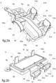
Fig. 2a and 2b are perspective views of the filter cover from the outer side and the housing side, respectively; -
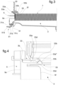
Fig. 3 is a cross-sectional view taken along the line III-III ofFig. 1 ; -
Fig. 4 is an enlarged scale view of a detail taken along the cross-section IV-IV ofFig. 1 ; -
Fig. 5 is a view, from inside a filter housing, of the air conditioning unit inFig. 1 , without the filtering element; -
Fig. 6 is a further perspective view of the filter housing from which the filter cover and filtering element have been removed; and -
Fig. 7 and 8 show a detail of the filter housing during different stages of mounting the filter cover. -
Fig. 1 shows a part of an air conditioning unit of a vehicle. In particular,Fig. 1 shows anenclosure 1 of plastics material, within which various components of the air conditioning unit are arranged in a conventional manner. In the portion of theenclosure 1 shown inFig. 1 , there is formed a filter housing 3 (not shown inFig. 1 , but shown inFig. 5 and 6 ) on which acover 5, shown in plan view inFig. 1 , is removably fixed. - The
filter housing 3 is adapted to receive afiltering element 7, shown inFig. 3 . In the example shown, thefiltering element 7 has a substantially plate-like shape and is formed from a zigzag-folded filtering sheet 2. The structure of the filtering element may be different from that depicted in the figures, and is not essential to the invention. Thefilter housing 3 may be, for example, a frame or a box, and is configured to permit a flow of fluid, e.g., air, to pass through thefiltering element 7 according to a direction approximately orthogonal to a pair of faces of the filtering element. - The
filter cover 5 is a plate-shaped element formed in one piece of plastics material. On thefilter cover 5 there may conventionally be provided a gasket (not shown) to seal thefilter cover 5 tightly onto an opening 3a of thefilter housing 3. - As may be seen in particular in
Fig. 1 , thefilter cover 5 has a substantially rectangular shape according to a plan view, comprising twolong sides short sides filter cover 5, an outer-side face 5e may also be identified, which in the mounted condition of thefilter cover 5 faces toward the outside, and a housing-side face 5f which is opposite to the outer-side face 5e and, in the mounted condition of thefilter cover 5, faces toward the inside of thefilter housing 3. More generally, the terms "outer" and "inner" as used in this description are to be understood as "outside the compartment defined by the filter housing" (specifically, outside the opening 3a) and "inside the compartment defined by the filter housing," respectively. - On a first side of the
filter cover 5, which in the example shown is one of the long sides denoted by 5a, there is formed a plurality of outer snap-fit connection elements 51 (according to a less effective embodiment, there may be only one outer snap-fit connection element). Each of the outer snap-fit connection elements 51 is formed as a formation protruding beyond the lateral edge of thefilter cover 5, as may be seen particularly inFig. 1 . As may be seen inFig. 1 and3 , each of the outer snap-fit connection elements 51 is configured to engage a relevantouter formation 31 formed close to theedge 3b of the opening 3a of thefilter housing 3. - Referring to
Fig. 2a and 2b , each outer snap-fit connection element 51 comprises asupport portion 51a that extends laterally toward the outside of thefilter cover 5. On a distal end of thesupport portion 51a there is formed an elasticallydeformable tab 51b extending in a direction substantially orthogonal to the plane of thefilter cover 5. Thetab 51a has, at one inner end, acoupling tooth 51c (seeFig. 3 ) and, at an outer end opposite the aforesaid inner end, a manuallyoperable release portion 51d. - The relevant
outer formation 31 formed near theedge 3b of the opening 3a of thefilter housing 3 comprises acoupling tooth 31a on one of its distal ends. Thecoupling tooth 31a has a sawtooth contour which, during the initial stage of the movement for mounting thefilter cover 5 on the filter housing 3 (from left to right in the representation inFig. 3 ), induces the deformation/rotation of thetab 51b, which thus overrides thecoupling tooth 31a, bringing thecoupling hook 51c behind the stepped part of the sawtooth contour of thecoupling tooth 31a. - To operate the release of the
filter cover 5, it is necessary to act with a finger on therelease portion 51d of thetab 51b to rotate it, and then lift thecoupling hook 51c and disengage it from thecoupling tooth 31a. - Referring to
Fig. 2a through 5 , thefilter cover 5 further comprises a plurality of inner snap-fit connection elements 53 formed on the secondlong side 5b (according to a less effective embodiment, there may be only one inner snap-fit connection element). Preferably, there is a number of inner snap-fit connection elements 53 equal to the number of outer snap-fit connection elements 51. Preferably, each inner snap-fit connection element 53 is, according to a plan view of the filter cover, aligned with a relevant outer snap-fit connection element 51. - The inner snap-
fit connection elements 53 protrude from the housing-side face 5f of thefilter cover 5 according to a direction substantially orthogonal to the plane of thefilter cover 5. The inner snap-fit connection elements 53 are configured to engage respectiveinner formations 33 formed inside thefilter housing 3. Eachinner connection element 53 comprises an elasticallydeformable tab 53a and has at one distal end a round-shaped coupling protrusion 53b. Thecoupling protrusion 53b protrudes laterally outwards from thetab 53a of theinner connection element 53. Preferably, thecoupling protrusion 53b is shaped like a dome, in particular a spherical dome. - Referring to
Fig. 3 through 8 , the relevantinner formation 33 formed inside thefilter housing 3 comprises agroove 33a extending from theedge 3b of theopening 3a of thefilter housing 3 in the longitudinal direction of thefilter housing 3. In the present description, "longitudinal direction" means the direction according to which the filteringelement 7 is inserted into thefilter housing 3 through theopening 3a, as well as the mounting direction of the filter cover 5 (in other words, the direction from left to right inFig. 3 ). - The
groove 33a is formed on a portion of the wall, partition, or protrusion of thefilter housing 3 that extends from theedge 3b of the opening 3a and faces toward the inside of thefilter housing 3. Thegroove 33a is adapted to receive thecoupling protrusion 53b of theinner connection element 53. Along thegroove 33a anobstruction 33b is arranged that separates thegroove 33a into afirst portion 33a' and asecond portion 33a". Along thefirst portion 33a', thecoupling protrusion 53b is capable of sliding in an initial stage of mounting thefilter cover 5 on the filter housing 3 (Fig. 7 ). At thesecond portion 33 a", thecoupling protrusion 53b is capable of snap-fitting to theobstruction 33b (Fig. 8 ). - The end of the
first portion 33a' of thegroove 33a has a ramp-shaped contour, which during the initial stage of the movement of mounting thefilter cover 5 on thefilter housing 3 induces the deformation of thetab 53a, which thus overrides theobstruction 33b, bringing thecoupling protrusion 53b behind theobstruction 33b. Thesecond portion 33a" of thegroove 33a at theobstruction 33b has a round-shaped contour that preferably matches with the contour of thecoupling protrusion 53b. - The
groove 33a is dimensioned in such a way that thecoupling protrusion 53b is capable of reaching thesecond portion 33a" when the outer snap-fit connection element 51 snap-fits to the relevantouter formation 31. - With the arrangement described above, when the outer snap-
fit connection element 51 is disengaged by manually acting on therelease portion 51d of thetab 51b, and the removal of thefilter cover 5 is thus operated, the inner snap-fit connection element 53 does not prevent the extraction of thefilter cover 5. - It is understood that the invention is not limited to the embodiments described and shown here, but instead may be subject to modifications relating to the shape and arrangement of parts and design and operating details, according to the numerous possible variants that will appear appropriate to those skilled in the art, and which are to be understood as included within the scope of the invention, as defined by the following claims.
Claims (9)
- A filter cover (5) configured to be removably fixed to a filter housing (3) adapted to receive a filtering element (7), the filter cover (5) being formed as a plate of plastics material having a substantially rectangular shape when viewed in plan view,wherein on a first side (5a) of the filter cover (5) there is formed at least one outer snap-fit connection element (51) protruding beyond a lateral edge of the filter cover (5) and configured to engage a respective outer formation (31) formed close to an edge (3b) of an opening (3a) of the filter housing (3), said at least one outer snap-fit connection element comprising an elastically deformable tab (51b) having a coupling hook (5 1c) at one end, and a manually operable release portion (51d) at an opposite end,the filter cover (5) being characterized in that on a second side (5b) of the filter cover (5), opposite to the first side (5a), there is formed at least one inner snap-fit connection element (53) protruding from a housing-side face (5f) of the filter cover (5) and configured to engage a respective inner formation (33) formed within the filter housing (3), said at least one inner snap-fit connection element comprising an elastically deformable tab (53a) having a round-shaped coupling protrusion (53b) at one end.
- The filter cover according to claim 1, wherein the first side (5a) and the second side (5b) of the filter cover (5) are the long sides of the substantially rectangular shape, and wherein on the first side (5a) there are formed more outer snap-fit connection elements (51), and on the second side (5b) there are formed more inner snap-fit connection elements (53).
- The filter cover according to claim 1 or 2, wherein the coupling protrusion (53b) protrudes laterally outwards from the tab (53a) of the inner snap-fit connection element (53).
- The filter cover according to any of the preceding claims, wherein the coupling protrusion (53b) is dome-shaped, preferably spherical-dome shaped.
- An assembly comprising a filter housing (3) adapted to receive a filtering element (7), and a filter cover (5) according to any of the preceding claims, configured to be removably fixed to the filter housing (3).
- The assembly according to claim 5, wherein said inner formation (33) comprises a groove (33a) extending from the edge (3b) of the opening (3a) of the filter housing (3) in the longitudinal direction of the filter housing (3), said groove facing toward the inside of the filter housing (3) and being adapted to receive the coupling protrusion (53b) of the inner snap-fit connection element (53), wherein along the groove (33a) there is arranged an obstruction (33b) separating the groove (33a) into a first portion (33a'), along which the coupling protrusion (53b) is slidable in an initial step of mounting the filter cover (5) to the filter housing (3), and a second portion (33a") at which the coupling protrusion (53b) is capable of snap-fitting to the obstruction (33b).
- The assembly according to claim 6, wherein the groove (33a) is dimensioned in such a way that the coupling protrusion (53b) is capable of reaching the second portion (33a") when the outer snap-fit connection element (51) snap-fits to the respective outer formation (31).
- The assembly according to any of claims from 5 to 7, wherein one end of the first portion (33a') of the groove (33a) at the obstruction (33b) has a ramp-shaped contour.
- The assembly according to any of claims from 5 to 8, wherein one end of the second portion (33a") of the groove (33a) at the obstruction (33b) has a round-shaped contour which preferably matches with the contour of the coupling protrusion (53b).
Priority Applications (1)
| Application Number | Priority Date | Filing Date | Title |
|---|---|---|---|
| MA65242A MA65242B1 (en) | 2022-07-06 | 2023-07-04 | Filter cover |
Applications Claiming Priority (1)
| Application Number | Priority Date | Filing Date | Title |
|---|---|---|---|
| IT102022000014281A IT202200014281A1 (en) | 2022-07-06 | 2022-07-06 | Filter cover with rounded hooks |
Publications (2)
| Publication Number | Publication Date |
|---|---|
| EP4302858A1 EP4302858A1 (en) | 2024-01-10 |
| EP4302858B1 true EP4302858B1 (en) | 2024-12-25 |
Family
ID=83439065
Family Applications (1)
| Application Number | Title | Priority Date | Filing Date |
|---|---|---|---|
| EP23183262.7A Active EP4302858B1 (en) | 2022-07-06 | 2023-07-04 | Filter cover |
Country Status (5)
| Country | Link |
|---|---|
| EP (1) | EP4302858B1 (en) |
| ES (1) | ES3014071T3 (en) |
| IT (1) | IT202200014281A1 (en) |
| MA (1) | MA65242B1 (en) |
| PL (1) | PL4302858T3 (en) |
Family Cites Families (3)
| Publication number | Priority date | Publication date | Assignee | Title |
|---|---|---|---|---|
| DE102008056793A1 (en) * | 2008-08-08 | 2010-02-18 | Carl Freudenberg Kg | Filter module with a filter element and a leaf guard |
| DE102017209578A1 (en) * | 2017-06-07 | 2018-12-13 | Hanon Systems | Housing, in particular filter housing and air conditioning system for a vehicle |
| US11572854B2 (en) * | 2020-09-30 | 2023-02-07 | Caterpillar Inc. | Filtration device having a latch mechanism |
-
2022
- 2022-07-06 IT IT102022000014281A patent/IT202200014281A1/en unknown
-
2023
- 2023-07-04 PL PL23183262.7T patent/PL4302858T3/en unknown
- 2023-07-04 MA MA65242A patent/MA65242B1/en unknown
- 2023-07-04 ES ES23183262T patent/ES3014071T3/en active Active
- 2023-07-04 EP EP23183262.7A patent/EP4302858B1/en active Active
Also Published As
| Publication number | Publication date |
|---|---|
| IT202200014281A1 (en) | 2024-01-06 |
| MA65242B1 (en) | 2025-03-28 |
| ES3014071T3 (en) | 2025-04-16 |
| PL4302858T3 (en) | 2025-03-31 |
| EP4302858A1 (en) | 2024-01-10 |
Similar Documents
| Publication | Publication Date | Title |
|---|---|---|
| US5472379A (en) | Air filter for the interior of motor vehicles | |
| JP5049285B2 (en) | Air filter for automotive ventilation system | |
| KR102223042B1 (en) | Filter frame | |
| CN101139997A (en) | Filter ventilator with a quick fix | |
| CN108211572A (en) | Frameless self-locking filter and the air purifier using the filter | |
| KR101926378B1 (en) | Double suction type air cleaner | |
| EP3964404A1 (en) | Material handling vehicle | |
| EP4302858A1 (en) | Filter cover | |
| JP4226864B2 (en) | Sliding lock device and air conditioner | |
| EP2495446A1 (en) | Elastic insulation system for an electric motor for reducing vibration transmission | |
| CN106796036A (en) | The outdoor unit of air conditioner | |
| US12293886B2 (en) | Switch device | |
| US7445546B2 (en) | Housing for an extractor hood and ventilator housing | |
| JP2964744B2 (en) | Vehicle air conditioner | |
| JP4703596B2 (en) | Electronic device cooling fan mounting structure | |
| KR102087816B1 (en) | Housing, in particular filter housing and air conditioning system for a vehicle | |
| US20160368344A1 (en) | Connecting pipe linking a thermal device of a motor vehicle to an apron of the vehicle | |
| US7575204B2 (en) | Arrangement for connecting a device's front panel | |
| JP2009236949A (en) | Image forming apparatus | |
| JP4522871B2 (en) | Image forming apparatus | |
| CN110154718B (en) | Structure of opening part of pipeline | |
| EP2008839B1 (en) | Air-conditioning control unit | |
| CN115916602A (en) | Siren support cover | |
| JPH09184639A (en) | Air conditioner | |
| EP3929449B1 (en) | Connection device for connecting two flat parts together without air leakage |
Legal Events
| Date | Code | Title | Description |
|---|---|---|---|
| PUAI | Public reference made under article 153(3) epc to a published international application that has entered the european phase |
Free format text: ORIGINAL CODE: 0009012 |
|
| STAA | Information on the status of an ep patent application or granted ep patent |
Free format text: STATUS: THE APPLICATION HAS BEEN PUBLISHED |
|
| AK | Designated contracting states |
Kind code of ref document: A1 Designated state(s): AL AT BE BG CH CY CZ DE DK EE ES FI FR GB GR HR HU IE IS IT LI LT LU LV MC ME MK MT NL NO PL PT RO RS SE SI SK SM TR |
|
| STAA | Information on the status of an ep patent application or granted ep patent |
Free format text: STATUS: REQUEST FOR EXAMINATION WAS MADE |
|
| 17P | Request for examination filed |
Effective date: 20240326 |
|
| RAV | Requested validation state of the european patent: fee paid |
Extension state: MA Effective date: 20240326 |
|
| RBV | Designated contracting states (corrected) |
Designated state(s): AL AT BE BG CH CY CZ DE DK EE ES FI FR GB GR HR HU IE IS IT LI LT LU LV MC ME MK MT NL NO PL PT RO RS SE SI SK SM TR |
|
| GRAP | Despatch of communication of intention to grant a patent |
Free format text: ORIGINAL CODE: EPIDOSNIGR1 |
|
| STAA | Information on the status of an ep patent application or granted ep patent |
Free format text: STATUS: GRANT OF PATENT IS INTENDED |
|
| INTG | Intention to grant announced |
Effective date: 20240603 |
|
| GRAJ | Information related to disapproval of communication of intention to grant by the applicant or resumption of examination proceedings by the epo deleted |
Free format text: ORIGINAL CODE: EPIDOSDIGR1 |
|
| STAA | Information on the status of an ep patent application or granted ep patent |
Free format text: STATUS: REQUEST FOR EXAMINATION WAS MADE |
|
| GRAS | Grant fee paid |
Free format text: ORIGINAL CODE: EPIDOSNIGR3 |
|
| STAA | Information on the status of an ep patent application or granted ep patent |
Free format text: STATUS: GRANT OF PATENT IS INTENDED |
|
| GRAP | Despatch of communication of intention to grant a patent |
Free format text: ORIGINAL CODE: EPIDOSNIGR1 |
|
| INTG | Intention to grant announced |
Effective date: 20240930 |
|
| GRAA | (expected) grant |
Free format text: ORIGINAL CODE: 0009210 |
|
| STAA | Information on the status of an ep patent application or granted ep patent |
Free format text: STATUS: THE PATENT HAS BEEN GRANTED |
|
| AK | Designated contracting states |
Kind code of ref document: B1 Designated state(s): AL AT BE BG CH CY CZ DE DK EE ES FI FR GB GR HR HU IE IS IT LI LT LU LV MC ME MK MT NL NO PL PT RO RS SE SI SK SM TR |
|
| REG | Reference to a national code |
Ref country code: GB Ref legal event code: FG4D |
|
| REG | Reference to a national code |
Ref country code: CH Ref legal event code: EP |
|
| REG | Reference to a national code |
Ref country code: DE Ref legal event code: R096 Ref document number: 602023001481 Country of ref document: DE |
|
| REG | Reference to a national code |
Ref country code: IE Ref legal event code: FG4D |
|
| REG | Reference to a national code |
Ref country code: MA Ref legal event code: VAGR Ref document number: 65242 Country of ref document: MA Kind code of ref document: B1 |
|
| REG | Reference to a national code |
Ref country code: LT Ref legal event code: MG9D |
|
| PG25 | Lapsed in a contracting state [announced via postgrant information from national office to epo] |
Ref country code: HR Free format text: LAPSE BECAUSE OF FAILURE TO SUBMIT A TRANSLATION OF THE DESCRIPTION OR TO PAY THE FEE WITHIN THE PRESCRIBED TIME-LIMIT Effective date: 20241225 |
|
| PG25 | Lapsed in a contracting state [announced via postgrant information from national office to epo] |
Ref country code: FI Free format text: LAPSE BECAUSE OF FAILURE TO SUBMIT A TRANSLATION OF THE DESCRIPTION OR TO PAY THE FEE WITHIN THE PRESCRIBED TIME-LIMIT Effective date: 20241225 |
|
| PG25 | Lapsed in a contracting state [announced via postgrant information from national office to epo] |
Ref country code: BG Free format text: LAPSE BECAUSE OF FAILURE TO SUBMIT A TRANSLATION OF THE DESCRIPTION OR TO PAY THE FEE WITHIN THE PRESCRIBED TIME-LIMIT Effective date: 20241225 |
|
| REG | Reference to a national code |
Ref country code: ES Ref legal event code: FG2A Ref document number: 3014071 Country of ref document: ES Kind code of ref document: T3 Effective date: 20250416 |
|
| PG25 | Lapsed in a contracting state [announced via postgrant information from national office to epo] |
Ref country code: NO Free format text: LAPSE BECAUSE OF FAILURE TO SUBMIT A TRANSLATION OF THE DESCRIPTION OR TO PAY THE FEE WITHIN THE PRESCRIBED TIME-LIMIT Effective date: 20250325 |
|
| PG25 | Lapsed in a contracting state [announced via postgrant information from national office to epo] |
Ref country code: GR Free format text: LAPSE BECAUSE OF FAILURE TO SUBMIT A TRANSLATION OF THE DESCRIPTION OR TO PAY THE FEE WITHIN THE PRESCRIBED TIME-LIMIT Effective date: 20250326 Ref country code: LV Free format text: LAPSE BECAUSE OF FAILURE TO SUBMIT A TRANSLATION OF THE DESCRIPTION OR TO PAY THE FEE WITHIN THE PRESCRIBED TIME-LIMIT Effective date: 20241225 |
|
| PG25 | Lapsed in a contracting state [announced via postgrant information from national office to epo] |
Ref country code: RS Free format text: LAPSE BECAUSE OF FAILURE TO SUBMIT A TRANSLATION OF THE DESCRIPTION OR TO PAY THE FEE WITHIN THE PRESCRIBED TIME-LIMIT Effective date: 20250325 |
|
| REG | Reference to a national code |
Ref country code: NL Ref legal event code: MP Effective date: 20241225 |
|
| PG25 | Lapsed in a contracting state [announced via postgrant information from national office to epo] |
Ref country code: NL Free format text: LAPSE BECAUSE OF FAILURE TO SUBMIT A TRANSLATION OF THE DESCRIPTION OR TO PAY THE FEE WITHIN THE PRESCRIBED TIME-LIMIT Effective date: 20241225 |
|
| REG | Reference to a national code |
Ref country code: AT Ref legal event code: MK05 Ref document number: 1753720 Country of ref document: AT Kind code of ref document: T Effective date: 20241225 |
|
| PG25 | Lapsed in a contracting state [announced via postgrant information from national office to epo] |
Ref country code: SM Free format text: LAPSE BECAUSE OF FAILURE TO SUBMIT A TRANSLATION OF THE DESCRIPTION OR TO PAY THE FEE WITHIN THE PRESCRIBED TIME-LIMIT Effective date: 20241225 |
|
| PG25 | Lapsed in a contracting state [announced via postgrant information from national office to epo] |
Ref country code: IS Free format text: LAPSE BECAUSE OF FAILURE TO SUBMIT A TRANSLATION OF THE DESCRIPTION OR TO PAY THE FEE WITHIN THE PRESCRIBED TIME-LIMIT Effective date: 20250425 |
|
| PG25 | Lapsed in a contracting state [announced via postgrant information from national office to epo] |
Ref country code: PT Free format text: LAPSE BECAUSE OF FAILURE TO SUBMIT A TRANSLATION OF THE DESCRIPTION OR TO PAY THE FEE WITHIN THE PRESCRIBED TIME-LIMIT Effective date: 20250428 |
|
| PG25 | Lapsed in a contracting state [announced via postgrant information from national office to epo] |
Ref country code: EE Free format text: LAPSE BECAUSE OF FAILURE TO SUBMIT A TRANSLATION OF THE DESCRIPTION OR TO PAY THE FEE WITHIN THE PRESCRIBED TIME-LIMIT Effective date: 20241225 |
|
| PG25 | Lapsed in a contracting state [announced via postgrant information from national office to epo] |
Ref country code: AT Free format text: LAPSE BECAUSE OF FAILURE TO SUBMIT A TRANSLATION OF THE DESCRIPTION OR TO PAY THE FEE WITHIN THE PRESCRIBED TIME-LIMIT Effective date: 20241225 |
|
| PG25 | Lapsed in a contracting state [announced via postgrant information from national office to epo] |
Ref country code: SK Free format text: LAPSE BECAUSE OF FAILURE TO SUBMIT A TRANSLATION OF THE DESCRIPTION OR TO PAY THE FEE WITHIN THE PRESCRIBED TIME-LIMIT Effective date: 20241225 |
|
| PG25 | Lapsed in a contracting state [announced via postgrant information from national office to epo] |
Ref country code: IT Free format text: LAPSE BECAUSE OF FAILURE TO SUBMIT A TRANSLATION OF THE DESCRIPTION OR TO PAY THE FEE WITHIN THE PRESCRIBED TIME-LIMIT Effective date: 20241225 |
|
| PG25 | Lapsed in a contracting state [announced via postgrant information from national office to epo] |
Ref country code: SE Free format text: LAPSE BECAUSE OF FAILURE TO SUBMIT A TRANSLATION OF THE DESCRIPTION OR TO PAY THE FEE WITHIN THE PRESCRIBED TIME-LIMIT Effective date: 20241225 |
|
| REG | Reference to a national code |
Ref country code: DE Ref legal event code: R097 Ref document number: 602023001481 Country of ref document: DE |
|
| PGFP | Annual fee paid to national office [announced via postgrant information from national office to epo] |
Ref country code: ES Payment date: 20250801 Year of fee payment: 3 |
|
| PG25 | Lapsed in a contracting state [announced via postgrant information from national office to epo] |
Ref country code: DK Free format text: LAPSE BECAUSE OF FAILURE TO SUBMIT A TRANSLATION OF THE DESCRIPTION OR TO PAY THE FEE WITHIN THE PRESCRIBED TIME-LIMIT Effective date: 20241225 |
|
| PLBE | No opposition filed within time limit |
Free format text: ORIGINAL CODE: 0009261 |
|
| STAA | Information on the status of an ep patent application or granted ep patent |
Free format text: STATUS: NO OPPOSITION FILED WITHIN TIME LIMIT |
|
| VSFP | Annual fee paid to validation state [announced via postgrant information from national office to epo] |
Ref country code: MA Payment date: 20250703 Year of fee payment: 3 |
|
| 26N | No opposition filed |
Effective date: 20250926 |
|
| REG | Reference to a national code |
Ref country code: DE Ref legal event code: R119 Ref document number: 602023001481 Country of ref document: DE |
|
| PG25 | Lapsed in a contracting state [announced via postgrant information from national office to epo] |
Ref country code: LU Free format text: LAPSE BECAUSE OF NON-PAYMENT OF DUE FEES Effective date: 20250704 |
|
| REG | Reference to a national code |
Ref country code: BE Ref legal event code: MM Effective date: 20250731 |
|
| PG25 | Lapsed in a contracting state [announced via postgrant information from national office to epo] |
Ref country code: DE Free format text: LAPSE BECAUSE OF NON-PAYMENT OF DUE FEES Effective date: 20260203 |
|
| PG25 | Lapsed in a contracting state [announced via postgrant information from national office to epo] |
Ref country code: BE Free format text: LAPSE BECAUSE OF NON-PAYMENT OF DUE FEES Effective date: 20250731 |
|
| PG25 | Lapsed in a contracting state [announced via postgrant information from national office to epo] |
Ref country code: LT Free format text: LAPSE BECAUSE OF FAILURE TO SUBMIT A TRANSLATION OF THE DESCRIPTION OR TO PAY THE FEE WITHIN THE PRESCRIBED TIME-LIMIT Effective date: 20241225 |
|
| PGFP | Annual fee paid to national office [announced via postgrant information from national office to epo] |
Ref country code: PL Payment date: 20260616 Year of fee payment: 4 |
|
| PG25 | Lapsed in a contracting state [announced via postgrant information from national office to epo] |
Ref country code: IE Free format text: LAPSE BECAUSE OF NON-PAYMENT OF DUE FEES Effective date: 20250704 |
|
| PGFP | Annual fee paid to national office [announced via postgrant information from national office to epo] |
Ref country code: RO Payment date: 20260626 Year of fee payment: 4 |
|
| PG25 | Lapsed in a contracting state [announced via postgrant information from national office to epo] |
Ref country code: MC Free format text: LAPSE BECAUSE OF FAILURE TO SUBMIT A TRANSLATION OF THE DESCRIPTION OR TO PAY THE FEE WITHIN THE PRESCRIBED TIME-LIMIT Effective date: 20241225 |
|
| PGFP | Annual fee paid to national office [announced via postgrant information from national office to epo] |
Ref country code: CZ Payment date: 20260601 Year of fee payment: 4 |
|
| PGFP | Annual fee paid to national office [announced via postgrant information from national office to epo] |
Ref country code: FR Payment date: 20260630 Year of fee payment: 4 |
|
| PG25 | Lapsed in a contracting state [announced via postgrant information from national office to epo] |
Ref country code: CY Free format text: LAPSE BECAUSE OF FAILURE TO SUBMIT A TRANSLATION OF THE DESCRIPTION OR TO PAY THE FEE WITHIN THE PRESCRIBED TIME-LIMIT Effective date: 20241225 |