EP4300794A1 - Electric motor - Google Patents
Electric motor Download PDFInfo
- Publication number
- EP4300794A1 EP4300794A1 EP21927826.4A EP21927826A EP4300794A1 EP 4300794 A1 EP4300794 A1 EP 4300794A1 EP 21927826 A EP21927826 A EP 21927826A EP 4300794 A1 EP4300794 A1 EP 4300794A1
- Authority
- EP
- European Patent Office
- Prior art keywords
- motor
- stator
- end surface
- resin portion
- wall portion
- Prior art date
- Legal status (The legal status is an assumption and is not a legal conclusion. Google has not performed a legal analysis and makes no representation as to the accuracy of the status listed.)
- Withdrawn
Links
Images



Classifications
-
- H—ELECTRICITY
- H02—GENERATION; CONVERSION OR DISTRIBUTION OF ELECTRIC POWER
- H02K—DYNAMO-ELECTRIC MACHINES
- H02K1/00—Details of the magnetic circuit
- H02K1/06—Details of the magnetic circuit characterised by the shape, form or construction
- H02K1/12—Stationary parts of the magnetic circuit
- H02K1/18—Means for mounting or fastening magnetic stationary parts on to, or to, the stator structures
-
- H—ELECTRICITY
- H02—GENERATION; CONVERSION OR DISTRIBUTION OF ELECTRIC POWER
- H02K—DYNAMO-ELECTRIC MACHINES
- H02K1/00—Details of the magnetic circuit
- H02K1/06—Details of the magnetic circuit characterised by the shape, form or construction
- H02K1/12—Stationary parts of the magnetic circuit
- H02K1/14—Stator cores with salient poles
- H02K1/146—Stator cores with salient poles consisting of a generally annular yoke with salient poles
-
- H—ELECTRICITY
- H02—GENERATION; CONVERSION OR DISTRIBUTION OF ELECTRIC POWER
- H02K—DYNAMO-ELECTRIC MACHINES
- H02K1/00—Details of the magnetic circuit
- H02K1/06—Details of the magnetic circuit characterised by the shape, form or construction
- H02K1/12—Stationary parts of the magnetic circuit
- H02K1/18—Means for mounting or fastening magnetic stationary parts on to, or to, the stator structures
- H02K1/185—Means for mounting or fastening magnetic stationary parts on to, or to, the stator structures to outer stators
-
- H—ELECTRICITY
- H02—GENERATION; CONVERSION OR DISTRIBUTION OF ELECTRIC POWER
- H02K—DYNAMO-ELECTRIC MACHINES
- H02K21/00—Synchronous motors having permanent magnets; Synchronous generators having permanent magnets
- H02K21/12—Synchronous motors having permanent magnets; Synchronous generators having permanent magnets with stationary armatures and rotating magnets
- H02K21/14—Synchronous motors having permanent magnets; Synchronous generators having permanent magnets with stationary armatures and rotating magnets with magnets rotating within the armatures
- H02K21/16—Synchronous motors having permanent magnets; Synchronous generators having permanent magnets with stationary armatures and rotating magnets with magnets rotating within the armatures having annular armature cores with salient poles
-
- H—ELECTRICITY
- H02—GENERATION; CONVERSION OR DISTRIBUTION OF ELECTRIC POWER
- H02K—DYNAMO-ELECTRIC MACHINES
- H02K3/00—Details of windings
- H02K3/04—Windings characterised by the conductor shape, form or construction, e.g. with bar conductors
- H02K3/28—Layout of windings or of connections between windings
-
- H—ELECTRICITY
- H02—GENERATION; CONVERSION OR DISTRIBUTION OF ELECTRIC POWER
- H02K—DYNAMO-ELECTRIC MACHINES
- H02K3/00—Details of windings
- H02K3/32—Windings characterised by the shape, form or construction of the insulation
- H02K3/34—Windings characterised by the shape, form or construction of the insulation between conductors or between conductor and core, e.g. slot insulation
- H02K3/345—Windings characterised by the shape, form or construction of the insulation between conductors or between conductor and core, e.g. slot insulation between conductor and core, e.g. slot insulation
-
- H—ELECTRICITY
- H02—GENERATION; CONVERSION OR DISTRIBUTION OF ELECTRIC POWER
- H02K—DYNAMO-ELECTRIC MACHINES
- H02K3/00—Details of windings
- H02K3/46—Fastening of windings on the stator or rotor structure
- H02K3/52—Fastening salient pole windings or connections thereto
- H02K3/521—Fastening salient pole windings or connections thereto applicable to stators only
- H02K3/522—Fastening salient pole windings or connections thereto applicable to stators only for generally annular cores with salient poles
-
- H—ELECTRICITY
- H02—GENERATION; CONVERSION OR DISTRIBUTION OF ELECTRIC POWER
- H02K—DYNAMO-ELECTRIC MACHINES
- H02K5/00—Casings; Enclosures; Supports
- H02K5/04—Casings or enclosures characterised by the shape, form or construction thereof
- H02K5/08—Insulating casings
-
- H—ELECTRICITY
- H02—GENERATION; CONVERSION OR DISTRIBUTION OF ELECTRIC POWER
- H02K—DYNAMO-ELECTRIC MACHINES
- H02K7/00—Arrangements for handling mechanical energy structurally associated with dynamo-electric machines, e.g. structural association with mechanical driving motors or auxiliary dynamo-electric machines
- H02K7/08—Structural association with bearings
- H02K7/083—Structural association with bearings radially supporting the rotary shaft at both ends of the rotor
-
- H—ELECTRICITY
- H02—GENERATION; CONVERSION OR DISTRIBUTION OF ELECTRIC POWER
- H02K—DYNAMO-ELECTRIC MACHINES
- H02K2213/00—Specific aspects, not otherwise provided for and not covered by codes H02K2201/00 - H02K2211/00
- H02K2213/03—Machines characterised by numerical values, ranges, mathematical expressions or similar information
-
- H—ELECTRICITY
- H02—GENERATION; CONVERSION OR DISTRIBUTION OF ELECTRIC POWER
- H02K—DYNAMO-ELECTRIC MACHINES
- H02K5/00—Casings; Enclosures; Supports
- H02K5/04—Casings or enclosures characterised by the shape, form or construction thereof
- H02K5/16—Means for supporting bearings, e.g. insulating supports or means for fitting bearings in the bearing-shields
- H02K5/173—Means for supporting bearings, e.g. insulating supports or means for fitting bearings in the bearing-shields using bearings with rolling contact, e.g. ball bearings
- H02K5/1732—Means for supporting bearings, e.g. insulating supports or means for fitting bearings in the bearing-shields using bearings with rolling contact, e.g. ball bearings radially supporting the rotary shaft at both ends of the rotor
Definitions
- the present disclosure relates to a motor.
- Patent Literature 1 Japanese Patent Application Publication No. 2005-198440 (see, e.g., FIG. 1 )
- An object of the present disclosure is to reduce the reduction in the amount of magnetic flux flowing from the rotor main body to the stator while saving the cost.
- a motor includes: a rotor main body supported by a rotary shaft; and a stator, wherein the stator includes: a stator core having a first end surface that is one end surface in an axial direction of the rotary shaft, and a second end surface that is another end surface in the axial direction, a length of the stator core in the axial direction being less than a length of the rotor main body in the axial direction; at least one flux capture member disposed on at least one of the first end surface and the second end surface and made of magnetic material, the at least one flux capture member capturing a magnetic flux of the rotor main body; and a molded resin portion covering the at least one flux capture member and the stator core.
- the present disclosure makes it possible to reduce the reduction in the amount of magnetic flux flowing from the rotor main body to the stator while saving the cost.
- each drawing shows an xyz orthogonal coordinate system.
- the z axis is a coordinate axis parallel to axes C of rotors of motors.
- the x axis is a coordinate axis perpendicular to the z axis.
- the y axis is a coordinate axis perpendicular to both the x and z axes.
- FIG. 1 is a sectional view illustrating a configuration of a motor 100 according to a first embodiment.
- the motor 100 includes a rotor 1, a bearing 2 as a first bearing, a bearing 3 as a second bearing, a metal bracket 4 as a first bearing holder, and a molded stator 5 as a stator.
- the rotor 1 includes a shaft 11 as a rotary shaft, and a permanent magnet 12 as a rotor main body.
- the rotor 1 is rotatable about an axis C of the shaft 11.
- the shaft 11 projects in the +z-axis direction from the molded stator 5.
- a direction along a circumference of a circle centered on the axis C of the shaft 11 is referred to as a "circumferential direction" (e.g., circumferential direction R shown by an arrow in FIG. 2 to be described later).
- the z-axis direction is referred to as an "axial direction”
- directions perpendicular to the axial direction are referred to as "radial directions”.
- a side (i.e., the +z-axis side) on which the shaft 11 projects is referred to as a "load side”
- a side (i.e., the -z-axis side) opposite the load side of the shaft 11 is referred to as an "anti-load side”.
- the permanent magnet 12 is mounted to the shaft 11.
- the permanent magnet 12 is a cylindrical magnet elongated in the z-axis direction. North poles and south poles are alternately formed in an outer periphery of the permanent magnet 12.
- the rotor main body of the rotor 1 may be constituted by a rotor core fixed to the shaft 11 and the permanent magnet 12 mounted to the rotor core.
- the bearing 2 is a bearing that supports the load side of the shaft 11, and the bearing 3 is a bearing that supports the anti-load side of the shaft 11.
- the bearing 2 is held by the metal bracket (also referred to below as the "first metal bracket") 4.
- the metal bracket 4 is formed from, for example, a steel sheet.
- the bearing 3 is held by a bearing holder (i.e., bearing holder 52 to be described later) provided in the molded stator 5.
- the molded stator 5 includes a stator core 20, multiple coils 30, flux capture members 41 and 42, and a molded resin portion 50.
- FIG. 2 is a plan view illustrating part of the configuration of the stator core 20 illustrated in FIG. 1 .
- the stator core 20 has a first end surface 22c that is an end surface on one side (i.e., the +z-axis side) in the z-axis direction, and a second end surface 22d that is an end surface on the other side (i.e., the -z-axis side) in the z-axis direction.
- the stator core 20 includes a yoke 21 extending in the circumferential direction R, and multiple teeth 22.
- the multiple teeth 22 are arranged at predetermined intervals in the circumferential direction R.
- a slot 23 is formed between each two of the multiple teeth 22 adjacent to each other in the circumferential direction R.
- the slots 23 are spaces in which the coils 30 are accommodated.
- the multiple coils 30 illustrated in FIG. 1 are wound around the respective teeth 22.
- the multiple teeth 22 face the rotor 1 (see FIG. 1 ) in radial directions.
- Each of the multiple teeth 22 includes a tooth main body 22a and a tooth tip 22b.
- the tooth main body 22a extends inward in a radial direction from the yoke 21.
- the tooth tip 22b is located inward from the tooth main body 22a in the radial direction, and is wider than the tooth main body 22a in the circumferential direction R.
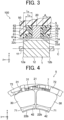
- FIG. 3 is an enlarged sectional view illustrating part of the configuration of the motor 100 illustrated in FIG. 1 .
- L 1 a first length that is a length of the stator core 20 in the z-axis direction
- L 2 a second length that is a length of the permanent magnet 12 in the z-axis direction
- the length L 1 is less than the length L 2 . That is, the lengths L 1 and L 2 satisfy the following formula (1): L 1 ⁇ L 2 .
- the stator core 20 includes multiple electromagnetic steel sheets (not illustrated) stacked in the z-axis direction.
- the lengths L 1 and L 2 satisfying formula (1) since the number of electromagnetic steel sheets provided in the stator core 20 is reduced, the cost of the stator core 20 can be reduced. Thus, the cost of the motor 100 can be reduced.
- the first end surface 22c and second end surface 22d of the stator core 20 are located between an end surface 12a of the permanent magnet 12 on the +z-axis side and an end surface 12b of the permanent magnet 12 on the -z-axis side.
- the motor 100 can be implemented such that one of the first end surface 22c and second end surface 22d is not located between the end surface 12a of the permanent magnet 12 on the +z-axis side and the end surface 12b of the permanent magnet 12 on the -z-axis side.
- the second end surface 22d of the stator core 20 may be located outward from the end surface 12b of the permanent magnet 12 on the -z-axis side in the axial direction.
- the length of a stator core in the z-axis direction is less than the length of a rotor main body (in the first embodiment, the permanent magnet 12) in the z-axis direction
- the magnetic flux generated from the portion of the rotor main body that does not face the stator core in radial directions is less likely to flow to the stator.
- the amount of magnetic flux flowing from the rotor main body to the stator is reduced. In this case, the efficiency of the motor is reduced.
- the flux capture members 41 and 42 are respectively disposed on first end surfaces 22c and second end surfaces 22d of the teeth 22.
- the flux capture members 41 and 42 are made of magnetic material, and capture the magnetic flux of the permanent magnet 12. Thereby, the magnetic flux generated from a portion (e.g., the first end surface 12a and second end surface 12b of the permanent magnet 12) of the permanent magnet 12 that does not face the stator core 20 in radial directions easily flows to the stator core 20 and coils 30 through the flux capture members 41 and 42. This can prevent reduction in the efficiency of the motor 100.
- the flux capture members 41 and 42 are disposed on the teeth 22 of the stator core 20, the flux capture members 41 and 42 are located close to the permanent magnet 12, and thus the magnetic flux of the permanent magnet 12 is easily captured by the flux capture members 41 and 42.
- the whole of the surface of each of the flux capture members 41 and 42 facing inward in radial directions faces an inner periphery of the permanent magnet 12 in radial directions. It is possible that at least part of the surface facing inward in radial directions faces the inner periphery of the permanent magnet 12.
- the molded stator 5 may be implemented such that it does not include the flux capture members 42 of the flux capture members 41 and 42.
- the flux capture members 41 and 42 are, for example, metal pieces made of metal. Specifically, the flux capture members 41 and 42 are iron pieces made of iron.
- the flux capture members 41 and 42 and stator core 20 are covered by the molded resin portion 50. Thereby, the flux capture members 41 and 42 are fixed to the stator core 20. Since the flux capture members 41 and 42 and stator core 20 are covered by the molded resin portion 50, no fasteners (e.g., bolts) for fixing the flux capture members 41 and 42 to the stator core 20 are required. This can reduce the number of parts of the motor 100, and simplify the assembly process of the motor 100.
- the end surfaces of the flux capture members 41 and 42 in the z-axis direction are in contact with the first end surface 22c and second end surface 22d, respectively.
- the flux capture members 41 and 42 are elongated in the z-axis direction. Thereby, the flux capture members 41 and 42 face end portions of the permanent magnet 12 on both sides in the z-axis direction, in radial directions.
- the magnetic flux of the permanent magnet 12 easily flows to the flux capture members 41 and 42, and thus the magnetic flux easily flows to the stator core 20 and coils 30 through the flux capture members 41 and 42.
- the molded resin portion 50 is made of, for example, thermosetting resin.
- the molded resin portion 50 is molded by, for example, injection molding. Also, the molded resin portion 50 is integrated with the stator core 20, coils 30, flux capture members 41 and 42, and a first insulator 60 and a second insulator 70 to be described later, by integral molding.
- the molded resin portion 50 includes an opening (also referred to below as the "first opening") 51, and the bearing holder 52.
- the metal bracket 4 is fixed in the opening 51.
- the metal bracket 4 is fixed in the opening 51 by, for example, press fitting.
- the bearing holder 52 is a recess in the molded resin portion 50 in which the bearing 3 on the anti-load side is held.
- a circuit board 8 is embedded in a portion of the molded resin portion 50 on the -z-axis side of the bearing holder 52.
- At least one power supply lead (not illustrated) for supplying power to the coils 30 is connected to the circuit board 8.
- the circuit board 8 is fixed to the second insulator 70 through winding terminals 7 connected to the coils 30.
- the molded stator 5 further includes the first insulator 60 and second insulator 70, which are disposed between the coils 30 and the stator core 20.
- the first insulator 60 and second insulator 70 are made of, for example, thermoplastic resin.
- the molded stator 5 may be implemented such that it does not include the first insulator 60 and second insulator 70.
- the first insulator 60 includes a first wall portion 61 as a first insulating portion, a second wall portion 62 as a second insulating portion, and a connecting portion 63.
- the first wall portion 61 covers end surfaces of the tooth tips 22b (see FIG. 2 ) of the teeth 22 on the +z-axis side, thereby insulating the teeth 22.
- the first wall portion 61 extends in the z-axis direction.
- the first wall portion 61 includes inner surfaces 61a facing the permanent magnet 12, and engagement portions 61b provided in the inner surfaces 61a.
- the engagement portions 61b engage with the flux capture members 41. This facilitates positioning of the flux capture members 41 in molding of the molded resin portion 50.
- the engagement portions 61b are, for example, grooves (also referred to as "recesses") obtained by cutting end portions of the inner surfaces 61a on the -z-axis side, and the flux capture members 41 are fitted in the grooves.
- the engagement portions 61b may be grooves obtained by recessing central portions of the inner surfaces 61a in the z-axis direction.
- the engagement portions 61b are not limited to grooves.
- the engagement portions 61b may be projections that engage with recesses provided in the flux capture members 41.
- the second wall portion 62 is located outward from the first wall portion 61 in radial directions.
- the second wall portion 62 covers an end surface of the yoke 21 on the +z-axis side, thereby insulating the yoke 21.
- the second wall portion 62 extends in the z-axis direction.
- L 3 a length of the second wall portion 62 in the z-axis direction
- L 4 a length of the first wall portion 61 in the z-axis direction
- the length L 3 is less than the length L 4 . That is, the lengths L 3 and L 4 satisfy the following formula (2): L 3 ⁇ L 4 .
- the connecting portion 63 connects the first wall portion 61 and the second wall portion 62.
- the connecting portion 63 extends in radial directions.
- the connecting portion 63 insulates end surfaces of the tooth main bodies 22a (see FIG. 2 ) of the teeth 22 on the +z-axis side.
- the second insulator 70 includes a third wall portion 71 as a first insulating portion, a fourth wall portion 72 as a second insulating portion, and a connecting portion 73.
- the third wall portion 71 insulates end surfaces of the tooth tips 22b (see FIG. 2 ) on the -z-axis side.
- the third wall portion 71 extends in the z-axis direction.
- the third wall portion 71 includes inner surfaces 71a facing the permanent magnet 12, and engagement portions 71b provided in the inner surfaces 71a.
- the engagement portions 71b engage with the flux capture members 42. This facilitates positioning of the flux capture members 42 in molding of the molded resin portion 50.
- the engagement portions 71b are, for example, grooves obtained by cutting end portions of the inner surfaces 71a on the -z-axis side, and the flux capture members 42 are fitted in the grooves.
- the engagement portions 71b may be grooves obtained by recessing central portions of the inner surfaces 71a in the z-axis direction. Also, the engagement portions 71b are not limited to grooves.
- the engagement portions 71b may be projections that engage with recesses provided in the flux capture members 42.
- resin layers made of the thermosetting resin that is the material of the molded resin portion 50 may be disposed between the flux capture members 41 and 42 and the teeth 22 in the z-axis direction.
- the first insulating portion insulating the teeth 22 may be constituted by the insulator and the resin layers.
- the fourth wall portion 72 is located outward from the third wall portion 71 in radial directions.
- the fourth wall portion 72 insulates an end surface of the yoke 21 (see FIG. 2 ) on the -z-axis side.
- the fourth wall portion 72 extends in the z-axis direction.
- the connecting portion 73 connects the third wall portion 71 and the fourth wall portion 72.
- the connecting portion 73 extends in radial directions.
- the connecting portion 73 insulates end surfaces of the tooth main bodies 22a (see FIG. 2 ) on the -z-axis side.
- Each coil 30 has a coil end portion 30a projecting from the tooth 22 outward in the z-axis direction.
- a height A of the coil end portion 30a in the z-axis direction decreases inward in a radial direction from a leading end of the coil end portion 30a.
- the height A of the coil end portion 30a decreases inward from an outer end of the coil end portion 30a in the radial direction.
- the height A is a height of coils stacked on an end surface of the tooth 22 in the z-axis direction by the coil 30 being wound around the tooth 22.
- the first wall portion 61 and third wall portion 71 respectively include the engagement portions 61b and 71b, which engage with the flux capture members 41 and 42.
- the first wall portion 61 is lower in strength than the second wall portion 62
- the third wall portion 71 is lower in strength than the fourth wall portion 72.
- the height A of the coil end portion 30a may be greatest at a central portion of the coil end portion 30a in the radial direction, and decrease inward or outward from the central portion in the radial direction.
- FIG. 4 is a plan view illustrating part of the configuration of the molded stator 5 illustrated in FIG. 1 .
- the motor 100 further includes the winding terminals 7 connected to the coils 30.
- the winding terminals 7 are inserted in terminal insertion holes (not illustrated) provided in the circuit board 8 (see FIG. 1 ).
- the winding terminals 7 are fixed to the fourth wall portion 72.
- the third wall portion 71 having the engagement portions 71b is lower in strength than the fourth wall portion 72.
- the winding terminals 7 can be fixed sufficiently firmly.
- the molded stator 5 further includes a crossover wire 31 connecting two coils 30 adjacent in the circumferential direction R.
- the molded stator 5 includes a crossover wire 31 connecting coils 30 of the same phase (e.g., U phase) adjacent to each other in the circumferential direction R.
- the crossover wire 31 is guided by the fourth wall portion 72, which is higher in strength than the third wall portion 71.
- the crossover wire 31 extends along a surface of the fourth wall portion 72 facing outward in radial directions.
- the crossover wire 31 is not in contact with the third wall portion 71.
- the third wall portion 71 can be prevented from being deformed by the crossover wire 31.
- the third wall portion 71 can be prevented from being inclined toward the permanent magnet 12 by the crossover wire 31.
- the motor 100 includes the permanent magnet 12 as a rotor main body having the first end surface 12a that is one end surface in the z-axis direction and the second end surface 12b that is the other end surface, and the molded stator 5.
- the molded stator 5 includes the stator core 20, and the length L 1 of the stator core 20 in the z-axis direction is less than the length L 2 of the permanent magnet 12 in the z-axis direction.
- the motor 100 includes the flux capture members 41 disposed on the first end surface 22c of the stator core 20 and made of magnetic material, the flux capture members 41 capturing the magnetic flux of the permanent magnet 12.
- the magnetic flux generated from the end portion of the permanent magnet 12 on the +z-axis side that does not face the stator core 20 in radial directions flows to the stator core 20 and coils 30 through the flux capture members 41.
- the reduction in the amount of magnetic flux flowing from the permanent magnet 12 of the rotor 1 to the molded stator 5 can be reduced.
- the motor 100 further includes the flux capture members 42 disposed on the second end surface 22d of the stator core 20 and made of magnetic material that captures the magnetic flux of the permanent magnet 12.
- the magnetic flux generated from the end portion of the permanent magnet 12 on the -z-axis side that does not face the stator core 20 in radial directions flows to the stator core 20 and coils 30 through the flux capture members 41.
- the flux capture members 41 and 42 and stator core 20 are covered by the molded resin portion 50. Thereby, no fasteners for mounting the flux capture members 41 and 42 to the stator core 20 are required. Thus, it is possible to reduce the number of parts of the motor 100, and simplify the assembly process of the motor 100.
- the flux capture members 41 and 42 are disposed on the teeth 22 of the stator core 20.
- the flux capture members 41 and 42 are located close to the permanent magnet 12, the magnetic flux of the permanent magnet 12 is easily captured by the flux capture members 41 and 42.
- the molded stator 5 includes the first wall portion 61 of the first insulator 60 that insulates the first end surfaces 22c of the teeth 22 on the +z-axis side, and the first wall portion 61 includes the engagement portions 61b that engage with the flux capture members 41. This facilitates positioning of the flux capture members 41 in molding of the molded resin portion 50.
- the molded stator 5 includes the third wall portion 71 of the second insulator 70 that insulates the second end surfaces 22d of the teeth 22 on the -z-axis side, and the third wall portion 71 includes the engagement portions 71b that engage with the flux capture members 42. This facilitates positioning of the flux capture members 42 in molding of the molded resin portion 50.
- the length L 3 of the second wall portion 62, which insulates the yoke 21, of the first insulator 60 in the z-axis direction is less than the length L 4 of the first wall portion 61, which supports the flux capture members 41, in the z-axis direction. This can reduce the amount of resin used in the first insulator 60.
- the molded stator 5 includes the coils 30 wound around the teeth 22 with the first insulator 60 and second insulator 70 therebetween, and the height A of the coil end portion 30a of each coil 30 decreases inward in a radial direction from the leading end of the coil end portion 30a. This reduces the winding stresses acting on the first wall portion 61 and third wall portion 71 during the winding operation, which can reduce deformation of the first wall portion 61 and third wall portion 71 due to the winding stresses.
- the motor 100 includes the winding terminals 7 connected to the coils 30, and the winding terminals 7 is fixed to the fourth wall portion 72 having a strength higher than that of the third wall portion 71. Thereby, the winding terminals 7 can be fixed sufficiently firmly.
- the molded stator 5 further includes the crossover wire 31 connecting adjacent two of the multiple coils 30, and the crossover wire 31 is guided by the fourth wall portion 72. Thereby, since the crossover wire 31 is not in contact with the third wall portion 71, the third wall portion 71 can be prevented from being deformed by the crossover wire 31.
- FIG. 5 is a sectional view illustrating a configuration of a motor 200 according to a second embodiment.
- elements that are the same as or correspond to those illustrated in FIG. 1 are given reference characters that are the same as those shown in FIG. 1 .
- a molded stator 205 of the motor 200 according to the second embodiment is different from the motor 100 according to the first embodiment in that it does not include the flux capture members 42. Otherwise, the motor 200 according to the second embodiment is the same as the motor 100 according to the first embodiment. Thus, the following description refers to FIG. 2 .
- the motor 200 includes a rotor 1 and the molded stator 205.
- the molded stator 205 includes a stator core 20, multiple coils 30, flux capture members 41, and a molded resin portion 250.
- the flux capture members provided in the molded stator 205 are only the flux capture members 41, the number of parts of the motor 200 is reduced, and the assembly process of the motor 200 can be simplified.
- the molded stator 205 further includes a first insulator 60 and a second insulator 270.
- the second insulator 270 includes a third wall portion 271.
- the third wall portion 271 insulates end surfaces of tooth tips 22b (see FIG. 2 ) on the -z-axis side.
- the third wall portion 271 extends in the z-axis direction.
- W 1 a thickness of the third wall portion 271 in radial directions
- W 2 a thickness in radial directions of a vertical portion 61c of a first wall portion 61 extending in the z-axis direction
- W 1 is greater than the thickness W 2 . That is, the thicknesses W 1 and W 2 satisfy the following formula (3): W 1 > W 2 .
- the third wall portion 271 is higher in strength than the first wall portion 61.
- the winding stress during the winding operation can be received by the third wall portion 271, and deformation of the first wall portion 61 by the winding stress can be reduced.
- a distance between the shaft 11 and a surface of the third wall portion 271 facing outward in radial directions (or an outer diameter of the third wall portion 271) may be greater than a distance between the shaft 11 and a surface of the first wall portion 61 facing outward in radial directions (or an outer diameter of the first wall portion 61). Also in this case, deformation of the first wall portion 61 by the winding stress can be reduced.
- a flux capture member 41 is disposed on a first end surface 22c (see FIG. 2 ) of each of multiple teeth 22. Two flux capture members 41 adjacent in the circumferential direction R are not connected together. Thus, while the motor 200 is rotating, the flux capture members 41 may be vibrated by the magnetic force of the permanent magnet 12 acting on the flux capture members 41.
- the thickness W 3 is greater than the thickness W 4 . That is, the thicknesses W 3 and W 4 satisfy the following formula (4) : W 3 > W 4 .
- the molded resin portion 250 includes a first resin portion 291 and a second resin portion 292.
- the first resin portion 291 covers a portion on the flux capture member 41 side of a plane V including an end surface 20a of the stator core 20 on the +z-axis side (or the first end surfaces 22c of the teeth 22 illustrated in FIG. 3 ).
- the second resin portion 292 covers a portion on the stator core 20 side of the plane V.
- the distance D 1 is less than the distance D 2 . That is, the distances D 1 and D 2 satisfy the following formula (5): D 1 ⁇ D 2 .
- the metal bracket 4 is fixed to the first resin portion 291 covering the flux capture members 41.
- the metal bracket 4 can be prevented from coming off due to the magnetic attractive force.
- the molded stator 205 further includes a mounting portion 255 extending outward in radial directions from the outer periphery 253 of the molded resin portion 250.
- the mounting portion 255 is mounted to a support of an object (e.g., a motor support provided in an outdoor unit) to which the motor 200 is mounted.
- the mounting portion 255 has insertion holes 255a in which fasteners (e.g., bolts) are inserted.
- the mounting portion 255 is provided in the second resin portion 292 of the molded resin portion 250.
- the second resin portion 292 covers the stator core 20, which is heavy in weight.
- the motor 200 can be fixed to the mounting object sufficiently firmly.
- the flux capture members provided in the molded stator 205 of the motor 200 are only the flux capture members 41. This can reduce the number of parts constituting the motor 200, and simplify the assembly process of the motor 200.
- the thickness W 1 is greater than the thickness W 2 .
- the third wall portion 271 is higher in strength than the first wall portion 61.
- the thickness W 3 is greater than the thickness W 4 .
- the molded resin portion 250 includes the first resin portion 291 covering the portion on the flux capture member 41 side of the plane V including the end surface 20a of the stator core 20 on the +z-axis side, and the second resin portion 292 covering the portion on the stator core 20 side of the plane V.
- the distance D 1 between the axis C and the outer periphery 291c of the first resin portion 291 is less than the distance D 2 between the axis C and the outer periphery 292c of the second resin portion 292. This can reduce the amount of resin used in the first resin portion 291.
- the metal bracket 4 is fixed to the first resin portion 291. While the motor 200 is rotating, magnetic attractive force acts between the permanent magnet 12 and the flux capture members 41 and between the permanent magnet 12 and the stator core 20. In the second embodiment, the magnetic attractive force between the permanent magnet 12 and the flux capture members 41 is smaller than the magnetic attractive force between the permanent magnet 12 and the stator core 20. Thus, the metal bracket 4 can be prevented from coming off due to the magnetic attractive force.
- the motor 200 further includes the mounting portion 255 mounted to a mounting object, and the mounting portion 255 is provided in the second resin portion 292 of the molded resin portion 250. Since the second resin portion 292 covers the stator core 20, which is heavy in weight, by the mounting portion 255 being provided in the second resin portion 292, the motor 200 can be fixed to the mounting object sufficiently firmly.
- FIG. 6 is a sectional view illustrating a configuration of a motor 200a according to a first modification of the second embodiment.
- elements that are the same as or correspond to those illustrated in FIG. 5 are given reference characters that are the same as those shown in FIG. 5 .
- the motor 200a according to the first modification of the second embodiment is different from the motor 200 according to the second embodiment in the shape of a molded resin portion 250a and the shape of a first insulator 260a. Otherwise, the motor 200a according to the first modification of the second embodiment is the same as the motor 200 according to the second embodiment.
- the following description refers to FIG. 5 .
- the motor 200a includes a rotor 1 and a molded stator 205a.
- the molded stator 205a includes a stator core 20, multiple coils 30, flux capture members 41, and the molded resin portion 250a.
- the molded resin portion 250a includes a first resin portion 291a covering a portion on the flux capture member 41 side of a plane V including an end surface 20a of the stator core 20 on the +z-axis side, and a second resin portion 292a covering a portion on the stator core 20 side of the plane V.
- D 11 a distance between the axis C and an outer periphery 291c of the first resin portion 291a
- D 12 a distance between the axis C and an outer periphery 292c of the second resin portion 292a
- the distance D 11 is greater than the distance D 12 . That is, the distances D 11 and D 12 satisfy the following formula (6) : D 11 > D 12 .
- the resin portion 250a surrounding the flux capture members 41 is thicker in radial directions, the resin portion has higher stiffness. This can further reduce vibration of the flux capture members 41 during rotation of the motor 200a.
- the molded stator 205a further includes the first insulator 260a and a second insulator 270a.
- the first insulator 260a includes a first wall portion 261a.
- the first wall portion 261 insulates end surfaces of tooth tips 22b (see FIG. 2 ) of teeth 22 on the +z-axis side.
- the first wall portion 261 extends in the z-axis direction.
- the second insulator 270a includes a third wall portion 271a.
- the third wall portion 271a insulates end surfaces of the tooth tips 22b (see FIG. 2 ) of the teeth 22 on the -z-axis side.
- the third wall portion 271a extends in the z-axis direction.
- the length L 5 is less than the length L 6 . That is, the lengths L 5 and L 6 satisfy the following formula (7): L 5 ⁇ L 6 .
- a winding operation of winding windings around the teeth 22 (see FIG. 2 ) with the first insulator 260a and second insulator 270a therebetween is performed by using a nozzle winding machine.
- a nozzle of the nozzle winding machine circles on the outer side of the first wall portion 261a of the first insulator 260a and the third wall portion 271a of the second insulator 270a in radial directions.
- the radius of rotation of the nozzle can be reduced.
- the nozzle can be made closer to the teeth 22, winding disorder of the windings during the winding operation can be reduced.
- the nozzle winding machine includes a former that is a winding guide for guiding the windings supplied from the nozzle to the slots 23 (see FIG. 2 )
- a former that is a winding guide for guiding the windings supplied from the nozzle to the slots 23 (see FIG. 2 )
- an inner diameter of the former can be reduced.
- the former can be downsized. Also, by virtue of the former being downsized, since the former can be made closer to the teeth 22 in the winding operation, winding disorder of the windings during the winding operation can be reduced.
- the distance D 11 between the axis C and the outer periphery 291c of the first resin portion 291a is greater than the distance D 12 between the axis C and the outer periphery 292c of the second resin portion 292a. That is, in the first modification of the second embodiment, the first resin portion 291a is thicker than the second resin portion 292a in radial directions. Thereby, since the resin portion of the molded resin portion 250a surrounding the flux capture members 41 is thicker in radial directions, the resin portion has higher stiffness. This can further reduce vibration of the flux capture members 41 during rotation of the motor 200a.
- the length L 5 of the third wall portion 271a in the z-axis direction is less than the length L 6 of the first wall portion 261a in the z-axis direction.
- the former of the nozzle winding machine can be downsized. Also, by virtue of the former being downsized, since the former can be made closer to the teeth 22, winding disorder of the windings during the winding operation can be reduced.
- FIG. 7 is a sectional view illustrating a configuration of a motor 200b according to a second modification of the second embodiment.
- elements that are the same as or correspond to those illustrated in FIG. 5 are given reference characters that are the same as those shown in FIG. 5 .
- the motor 200b according to the second modification of the second embodiment is different from the motor 200 according to the second embodiment in that it does not include the circuit board 8 and further includes a second metal bracket 209. Otherwise, the motor 200b according to the second modification of the second embodiment is different from the motor 200 according to the second embodiment.
- the motor 200b includes a rotor 1, a bearing 2, a bearing 3, a first metal bracket 4 as a first bearing holder, a molded stator 205b, and the second metal bracket 209 as a second bearing holder.
- the molded stator 205b includes a stator core 20, multiple coils 30, flux capture members 41, and a molded resin portion 250b.
- the molded resin portion 250b has a first opening 51 in which the first metal bracket 4 is fixed, and a second opening 53 in which the second metal bracket 209 is fixed.
- the second metal bracket 209 is a bearing holder that holds the bearing 3.
- the second metal bracket 209 is formed from, for example, a steel sheet. As above, by virtue of the motor 200b having the second metal bracket 209, since no bearing holder for holding the bearing 3 need be provided in the molded resin portion 250b, the amount of resin used in the molded resin portion 250b can be reduced.
- the second metal bracket 209 includes a cylindrical portion 209a, a flange portion 209b, and a fixing portion 209c.
- the cylindrical portion 209a is a portion of the second metal bracket 209 that holds the bearing 3.
- the flange portion 209b extends outward in radial directions from an end portion of the load side of the cylindrical portion 209a.
- the fixing portion 209c is a portion of the second metal bracket 209 that is fixed in the second opening 53 of the molded resin portion 250b.
- the fixing portion 209c is fixed in the second opening 53 by, for example, press fitting.
- the motor 200b further includes a winding terminal 7b that is connected to the coils 30 and fixed to a second insulator 270.
- a tip of the winding terminal 7b projects from an outer periphery 253 of the molded resin portion 250b. This allows the winding terminal 7b to be connected to a circuit board (not illustrated) provided outside the motor 200b.
- the tip of the winding terminal 7b may project from a bottom surface of the molded resin portion 250b.
- the motor 200b includes the molded stator 205b including the molded resin portion 250b, the bearing 3 that supports the anti-load side of the shaft 11, and the second metal bracket 209 that holds the bearing 3.
- the second metal bracket 209 is fixed to the molded resin portion 250b.
- FIG. 8 is a sectional view illustrating a configuration of a motor 200c according to a third modification of the second embodiment.
- elements that are the same as or correspond to those illustrated in FIG. 5 are given reference characters that are the same as those shown in FIG. 5 .
- the motor 200c according to the third modification of the second embodiment is different from the motor 200 according to the second embodiment in the shape of a molded resin portion 250c, the shape of a first metal bracket 204, and the shape of a second metal bracket 209. Otherwise, the motor 200c according to the third modification of the second embodiment is the same as the motor 200 according to the second embodiment.
- the motor 200c includes a rotor 1, a bearing 2, a bearing 3, the first metal bracket 204, a molded stator 205c, and the second metal bracket 209.
- the molded stator 205c includes a stator core 20, multiple coils 30, flux capture members 41, and the molded resin portion 250c.
- the molded resin portion 250c has a first opening 51 in which the first metal bracket 204 is fixed, and a second opening 53 in which a circuit board 8 is disposed.
- the first metal bracket 204 includes a cylindrical portion 204a and a flange portion 204b.
- the cylindrical portion 204a is a portion of the first metal bracket 204 that holds the bearing 2.
- the flange portion 204b extends outward in radial directions from an end portion of the cylindrical portion 204a on the anti-load side.
- a tip of the flange portion 204b of the first metal bracket 204 is covered by the molded resin portion 250c.
- the tip of the flange portion 204b is embedded in a groove 51c provided in the first opening 51.
- the assembly process of the motor 200c does not require a step of press-fitting the first metal bracket 204 into the molded resin portion 250c, the assembly process of the motor 200c can be simplified. It is sufficient that the molded resin portion 250c cover at least part (in the example illustrated in FIG. 8 , the tip of the flange portion 204b) of the first metal bracket 204. For example, the molded resin portion 250c may cover the whole of the first metal bracket 204.
- a flange portion 209b of the second metal bracket 209 extends outward in radial directions from an end portion of a cylindrical portion 209a on the anti-load side.
- a fixing portion 209c of the second metal bracket 209 is fixed to an outer periphery 253 of the molded resin portion 250c.
- the fixing portion 209c is fixed to the outer periphery 253 by, for example, press fitting.
- the molded stator 205c further includes a winding terminal 7c fixed to a second insulator 270, and the circuit board 8 connected to the winding terminal 7c.
- the circuit board 8 includes a hollow portion 8a in which a shaft 11 and the cylindrical portion 209a of the second metal bracket 209 are inserted.
- the molded resin portion 250c covers at least part (in the example illustrated in FIG. 8 , the tip of the flange portion 204b) of the first metal bracket 204 holding the bearing 2.
- the assembly process of the motor 200c does not require a step of press-fitting the first metal bracket 204 into the molded resin portion 250c, the assembly process of the motor 200c can be simplified.
Landscapes
- Engineering & Computer Science (AREA)
- Power Engineering (AREA)
- Iron Core Of Rotating Electric Machines (AREA)
- Insulation, Fastening Of Motor, Generator Windings (AREA)
- Valve Device For Special Equipments (AREA)
- Transition And Organic Metals Composition Catalysts For Addition Polymerization (AREA)
- Glass Compositions (AREA)
Abstract
Description
- The present disclosure relates to a motor.
- There is known a motor in which the length of a stator in an axial direction is generally equal to the length of a rotor main body in the axial direction. For example, see
Patent Literature 1. - Patent Literature 1:
Japanese Patent Application Publication No. 2005-198440 FIG. 1 ) - However, in the motor of
Patent Literature 1, when the length of the stator in the axial direction is made less than the length of the rotor main body in the axial direction in order to reduce the cost of the motor, the amount of magnetic flux flowing from the rotor main body to the stator is reduced. There is desired a technique for reducing the reduction in the amount of magnetic flux flowing from the rotor main body to the stator while saving the cost of the motor. - An object of the present disclosure is to reduce the reduction in the amount of magnetic flux flowing from the rotor main body to the stator while saving the cost.
- A motor according to an aspect of the present disclosure includes: a rotor main body supported by a rotary shaft; and a stator, wherein the stator includes: a stator core having a first end surface that is one end surface in an axial direction of the rotary shaft, and a second end surface that is another end surface in the axial direction, a length of the stator core in the axial direction being less than a length of the rotor main body in the axial direction; at least one flux capture member disposed on at least one of the first end surface and the second end surface and made of magnetic material, the at least one flux capture member capturing a magnetic flux of the rotor main body; and a molded resin portion covering the at least one flux capture member and the stator core.
- The present disclosure makes it possible to reduce the reduction in the amount of magnetic flux flowing from the rotor main body to the stator while saving the cost.
-
-
FIG. 1 is a sectional view illustrating a configuration of a motor according to a first embodiment. -
FIG. 2 is a plan view illustrating a configuration of a stator core of a stator of the motor illustrated inFIG. 1 . -
FIG. 3 is an enlarged sectional view illustrating part of the configuration of the motor illustrated inFIG. 1 . -
FIG. 4 is an enlarged plan view illustrating part of the configuration of the stator of the motor according to the first embodiment. -
FIG. 5 is a sectional view illustrating a configuration of a motor according to a second embodiment. -
FIG. 6 is a sectional view illustrating a configuration of a motor according to a first modification of the second embodiment. -
FIG. 7 is a sectional view illustrating a configuration of a motor according to a second modification of the second embodiment. -
FIG. 8 is a sectional view illustrating a configuration of a motor according to a third modification of the second embodiment. - Motors according to embodiments of the present disclosure will be described below with reference to the drawings. The following embodiments are merely examples, and can be modified in various ways within the scope of the present disclosure.
- To facilitate understanding of relationships between the drawings, each drawing shows an xyz orthogonal coordinate system. The z axis is a coordinate axis parallel to axes C of rotors of motors. The x axis is a coordinate axis perpendicular to the z axis. The y axis is a coordinate axis perpendicular to both the x and z axes.
-
FIG. 1 is a sectional view illustrating a configuration of amotor 100 according to a first embodiment. As illustrated inFIG. 1 , themotor 100 includes arotor 1, abearing 2 as a first bearing, abearing 3 as a second bearing, ametal bracket 4 as a first bearing holder, and a moldedstator 5 as a stator. - The
rotor 1 includes ashaft 11 as a rotary shaft, and apermanent magnet 12 as a rotor main body. Therotor 1 is rotatable about an axis C of theshaft 11. Theshaft 11 projects in the +z-axis direction from the moldedstator 5. In the following description, a direction along a circumference of a circle centered on the axis C of theshaft 11 is referred to as a "circumferential direction" (e.g., circumferential direction R shown by an arrow inFIG. 2 to be described later). Also, the z-axis direction is referred to as an "axial direction", and directions perpendicular to the axial direction are referred to as "radial directions". Also, a side (i.e., the +z-axis side) on which theshaft 11 projects is referred to as a "load side", and a side (i.e., the -z-axis side) opposite the load side of theshaft 11 is referred to as an "anti-load side". - The
permanent magnet 12 is mounted to theshaft 11. In the example illustrated inFIG. 1 , thepermanent magnet 12 is a cylindrical magnet elongated in the z-axis direction. North poles and south poles are alternately formed in an outer periphery of thepermanent magnet 12. The rotor main body of therotor 1 may be constituted by a rotor core fixed to theshaft 11 and thepermanent magnet 12 mounted to the rotor core. - The
bearing 2 is a bearing that supports the load side of theshaft 11, and thebearing 3 is a bearing that supports the anti-load side of theshaft 11. Thebearing 2 is held by the metal bracket (also referred to below as the "first metal bracket") 4. Themetal bracket 4 is formed from, for example, a steel sheet. Thebearing 3 is held by a bearing holder (i.e.,bearing holder 52 to be described later) provided in the moldedstator 5. - The
molded stator 5 includes astator core 20,multiple coils 30,flux capture members resin portion 50. -
FIG. 2 is a plan view illustrating part of the configuration of thestator core 20 illustrated inFIG. 1 . As illustrated inFIG. 2 , thestator core 20 has afirst end surface 22c that is an end surface on one side (i.e., the +z-axis side) in the z-axis direction, and asecond end surface 22d that is an end surface on the other side (i.e., the -z-axis side) in the z-axis direction. Also, thestator core 20 includes ayoke 21 extending in the circumferential direction R, andmultiple teeth 22. Themultiple teeth 22 are arranged at predetermined intervals in the circumferential directionR. A slot 23 is formed between each two of themultiple teeth 22 adjacent to each other in the circumferential direction R. Theslots 23 are spaces in which thecoils 30 are accommodated. Themultiple coils 30 illustrated inFIG. 1 are wound around therespective teeth 22. - The
multiple teeth 22 face the rotor 1 (seeFIG. 1 ) in radial directions. Each of themultiple teeth 22 includes a toothmain body 22a and atooth tip 22b. The toothmain body 22a extends inward in a radial direction from theyoke 21. Thetooth tip 22b is located inward from the toothmain body 22a in the radial direction, and is wider than the toothmain body 22a in the circumferential direction R. -
FIG. 3 is an enlarged sectional view illustrating part of the configuration of themotor 100 illustrated inFIG. 1 . As illustrated inFIG. 3 , when a first length that is a length of thestator core 20 in the z-axis direction is denoted by L1, and a second length that is a length of thepermanent magnet 12 in the z-axis direction is denoted by L2, the length L1 is less than the length L2. That is, the lengths L1 and L2 satisfy the following formula (1):
- Here, the
stator core 20 includes multiple electromagnetic steel sheets (not illustrated) stacked in the z-axis direction. By virtue of the lengths L1 and L2 satisfying formula (1), since the number of electromagnetic steel sheets provided in thestator core 20 is reduced, the cost of thestator core 20 can be reduced. Thus, the cost of themotor 100 can be reduced. In the first embodiment, thefirst end surface 22c andsecond end surface 22d of thestator core 20 are located between anend surface 12a of thepermanent magnet 12 on the +z-axis side and anend surface 12b of thepermanent magnet 12 on the -z-axis side. Themotor 100 can be implemented such that one of thefirst end surface 22c andsecond end surface 22d is not located between theend surface 12a of thepermanent magnet 12 on the +z-axis side and theend surface 12b of thepermanent magnet 12 on the -z-axis side. For example, thesecond end surface 22d of thestator core 20 may be located outward from theend surface 12b of thepermanent magnet 12 on the -z-axis side in the axial direction. - In general, when the length of a stator core in the z-axis direction is less than the length of a rotor main body (in the first embodiment, the permanent magnet 12) in the z-axis direction, the magnetic flux generated from the portion of the rotor main body that does not face the stator core in radial directions is less likely to flow to the stator. Specifically, since it is less likely to flow from end portions of the rotor main body on both sides in the z-axis direction to the stator core and coils, the amount of magnetic flux flowing from the rotor main body to the stator is reduced. In this case, the efficiency of the motor is reduced.
- In the
motor 100 according to the first embodiment, theflux capture members teeth 22. Theflux capture members permanent magnet 12. Thereby, the magnetic flux generated from a portion (e.g., thefirst end surface 12a andsecond end surface 12b of the permanent magnet 12) of thepermanent magnet 12 that does not face thestator core 20 in radial directions easily flows to thestator core 20 and coils 30 through theflux capture members motor 100. - Also, since the
flux capture members teeth 22 of thestator core 20, theflux capture members permanent magnet 12, and thus the magnetic flux of thepermanent magnet 12 is easily captured by theflux capture members FIG. 3 , the whole of the surface of each of theflux capture members permanent magnet 12 in radial directions. It is possible that at least part of the surface facing inward in radial directions faces the inner periphery of thepermanent magnet 12. Also, as illustrated inFIG. 5 to be described later or the like, the moldedstator 5 may be implemented such that it does not include theflux capture members 42 of theflux capture members - The
flux capture members flux capture members flux capture members stator core 20 are covered by the moldedresin portion 50. Thereby, theflux capture members stator core 20. Since theflux capture members stator core 20 are covered by the moldedresin portion 50, no fasteners (e.g., bolts) for fixing theflux capture members stator core 20 are required. This can reduce the number of parts of themotor 100, and simplify the assembly process of themotor 100. - Of end surfaces of the
flux capture members flux capture members stator core 20 side are in contact with thefirst end surface 22c andsecond end surface 22d, respectively. Also, theflux capture members flux capture members permanent magnet 12 on both sides in the z-axis direction, in radial directions. Thus, the magnetic flux of thepermanent magnet 12 easily flows to theflux capture members stator core 20 and coils 30 through theflux capture members - The molded
resin portion 50 is made of, for example, thermosetting resin. The moldedresin portion 50 is molded by, for example, injection molding. Also, the moldedresin portion 50 is integrated with thestator core 20, coils 30,flux capture members first insulator 60 and asecond insulator 70 to be described later, by integral molding. - The molded
resin portion 50 includes an opening (also referred to below as the "first opening") 51, and the bearingholder 52. Themetal bracket 4 is fixed in theopening 51. Themetal bracket 4 is fixed in theopening 51 by, for example, press fitting. - The bearing
holder 52 is a recess in the moldedresin portion 50 in which thebearing 3 on the anti-load side is held. Acircuit board 8 is embedded in a portion of the moldedresin portion 50 on the -z-axis side of the bearingholder 52. At least one power supply lead (not illustrated) for supplying power to thecoils 30 is connected to thecircuit board 8. Thecircuit board 8 is fixed to thesecond insulator 70 through windingterminals 7 connected to thecoils 30. - As illustrated in
FIGs. 1 and3 , the moldedstator 5 further includes thefirst insulator 60 andsecond insulator 70, which are disposed between thecoils 30 and thestator core 20. Thefirst insulator 60 andsecond insulator 70 are made of, for example, thermoplastic resin. The moldedstator 5 may be implemented such that it does not include thefirst insulator 60 andsecond insulator 70. - The
first insulator 60 includes afirst wall portion 61 as a first insulating portion, asecond wall portion 62 as a second insulating portion, and a connecting portion 63. Thefirst wall portion 61 covers end surfaces of thetooth tips 22b (seeFIG. 2 ) of theteeth 22 on the +z-axis side, thereby insulating theteeth 22. Thefirst wall portion 61 extends in the z-axis direction. - The
first wall portion 61 includesinner surfaces 61a facing thepermanent magnet 12, andengagement portions 61b provided in theinner surfaces 61a. Theengagement portions 61b engage with theflux capture members 41. This facilitates positioning of theflux capture members 41 in molding of the moldedresin portion 50. In the first embodiment, theengagement portions 61b are, for example, grooves (also referred to as "recesses") obtained by cutting end portions of theinner surfaces 61a on the -z-axis side, and theflux capture members 41 are fitted in the grooves. Theengagement portions 61b may be grooves obtained by recessing central portions of theinner surfaces 61a in the z-axis direction. Also, theengagement portions 61b are not limited to grooves. For example, theengagement portions 61b may be projections that engage with recesses provided in theflux capture members 41. - The
second wall portion 62 is located outward from thefirst wall portion 61 in radial directions. Thesecond wall portion 62 covers an end surface of theyoke 21 on the +z-axis side, thereby insulating theyoke 21. Thesecond wall portion 62 extends in the z-axis direction. When a length of thesecond wall portion 62 in the z-axis direction is denoted by L3, and a length of thefirst wall portion 61 in the z-axis direction is denoted by L4, the length L3 is less than the length L4. That is, the lengths L3 and L4 satisfy the following formula (2):
- This can reduce the amount of resin used in the
first insulator 60. - The connecting portion 63 connects the
first wall portion 61 and thesecond wall portion 62. The connecting portion 63 extends in radial directions. The connecting portion 63 insulates end surfaces of the toothmain bodies 22a (seeFIG. 2 ) of theteeth 22 on the +z-axis side. - The
second insulator 70 includes athird wall portion 71 as a first insulating portion, afourth wall portion 72 as a second insulating portion, and a connectingportion 73. Thethird wall portion 71 insulates end surfaces of thetooth tips 22b (seeFIG. 2 ) on the -z-axis side. Thethird wall portion 71 extends in the z-axis direction. - The
third wall portion 71 includesinner surfaces 71a facing thepermanent magnet 12, andengagement portions 71b provided in theinner surfaces 71a. Theengagement portions 71b engage with theflux capture members 42. This facilitates positioning of theflux capture members 42 in molding of the moldedresin portion 50. In the first embodiment, theengagement portions 71b are, for example, grooves obtained by cutting end portions of theinner surfaces 71a on the -z-axis side, and theflux capture members 42 are fitted in the grooves. Theengagement portions 71b may be grooves obtained by recessing central portions of theinner surfaces 71a in the z-axis direction. Also, theengagement portions 71b are not limited to grooves. For example, theengagement portions 71b may be projections that engage with recesses provided in theflux capture members 42. Also, resin layers made of the thermosetting resin that is the material of the moldedresin portion 50 may be disposed between theflux capture members teeth 22 in the z-axis direction. Thus, the first insulating portion insulating theteeth 22 may be constituted by the insulator and the resin layers. - The
fourth wall portion 72 is located outward from thethird wall portion 71 in radial directions. Thefourth wall portion 72 insulates an end surface of the yoke 21 (seeFIG. 2 ) on the -z-axis side. Thefourth wall portion 72 extends in the z-axis direction. The connectingportion 73 connects thethird wall portion 71 and thefourth wall portion 72. The connectingportion 73 extends in radial directions. The connectingportion 73 insulates end surfaces of the toothmain bodies 22a (seeFIG. 2 ) on the -z-axis side. - Each
coil 30 has acoil end portion 30a projecting from thetooth 22 outward in the z-axis direction. A height A of thecoil end portion 30a in the z-axis direction decreases inward in a radial direction from a leading end of thecoil end portion 30a. In the first embodiment, the height A of thecoil end portion 30a decreases inward from an outer end of thecoil end portion 30a in the radial direction. The height A is a height of coils stacked on an end surface of thetooth 22 in the z-axis direction by thecoil 30 being wound around thetooth 22. As described above, thefirst wall portion 61 andthird wall portion 71 respectively include theengagement portions flux capture members first wall portion 61 is lower in strength than thesecond wall portion 62, and thethird wall portion 71 is lower in strength than thefourth wall portion 72. The height A of thecoil end portion 30a may be greatest at a central portion of thecoil end portion 30a in the radial direction, and decrease inward or outward from the central portion in the radial direction. - When an operation (also referred to below as a "winding operation") of winding windings around the
teeth 22 with thefirst insulator 60 andsecond insulator 70 therebetween is performed, stresses (also referred to below as "winding stresses") occur in thefirst insulator 60 andsecond insulator 70 due to tensions of the windings acting on thefirst insulator 60 andsecond insulator 70. In the first embodiment, since the heights A of thecoil end portions 30a decrease inward from the leading ends of thecoil end portions 30a in the radial directions, the winding stress occurring in thefirst wall portion 61 is less than the winding stress occurring in thesecond wall portion 62. Also, the winding stress occurring in thethird wall portion 71 is less than the winding stress occurring in thefourth wall portion 72. Thus, thefirst wall portion 61 andthird wall portion 71 can be prevented from being deformed by the winding stresses. Specifically, thefirst wall portion 61 andthird wall portion 71 can be prevented from being inclined toward thepermanent magnet 12 by the winding stresses. -
FIG. 4 is a plan view illustrating part of the configuration of the moldedstator 5 illustrated inFIG. 1 . As illustrated inFIGs. 1 and4 , themotor 100 further includes the windingterminals 7 connected to thecoils 30. The windingterminals 7 are inserted in terminal insertion holes (not illustrated) provided in the circuit board 8 (seeFIG. 1 ). - The winding
terminals 7 are fixed to thefourth wall portion 72. As described above, thethird wall portion 71 having theengagement portions 71b is lower in strength than thefourth wall portion 72. Thus, by virtue of the windingterminals 7 being fixed to thefourth wall portion 72, the windingterminals 7 can be fixed sufficiently firmly. - As illustrated in
FIG. 4 , the moldedstator 5 further includes acrossover wire 31 connecting twocoils 30 adjacent in the circumferential direction R. Specifically, the moldedstator 5 includes acrossover wire 31 connectingcoils 30 of the same phase (e.g., U phase) adjacent to each other in the circumferential direction R. Thecrossover wire 31 is guided by thefourth wall portion 72, which is higher in strength than thethird wall portion 71. Specifically, thecrossover wire 31 extends along a surface of thefourth wall portion 72 facing outward in radial directions. As above, in the example illustrated inFIG. 4 , since thecrossover wire 31 is not guided by thethird wall portion 71, thecrossover wire 31 is not in contact with thethird wall portion 71.
Thereby, thethird wall portion 71 can be prevented from being deformed by thecrossover wire 31. Specifically, thethird wall portion 71 can be prevented from being inclined toward thepermanent magnet 12 by thecrossover wire 31. - In the first embodiment described above, the
motor 100 includes thepermanent magnet 12 as a rotor main body having thefirst end surface 12a that is one end surface in the z-axis direction and thesecond end surface 12b that is the other end surface, and the moldedstator 5. The moldedstator 5 includes thestator core 20, and the length L1 of thestator core 20 in the z-axis direction is less than the length L2 of thepermanent magnet 12 in the z-axis direction. Thereby, since the number of electromagnetic steel sheets used in thestator core 20 is reduced, the cost of the moldedstator 5 can be reduced. Thus, the cost of themotor 100 can be reduced. - Also, in the first embodiment, the
motor 100 includes theflux capture members 41 disposed on thefirst end surface 22c of thestator core 20 and made of magnetic material, theflux capture members 41 capturing the magnetic flux of thepermanent magnet 12. Thereby, the magnetic flux generated from the end portion of thepermanent magnet 12 on the +z-axis side that does not face thestator core 20 in radial directions flows to thestator core 20 and coils 30 through theflux capture members 41. Thus, the reduction in the amount of magnetic flux flowing from thepermanent magnet 12 of therotor 1 to the moldedstator 5 can be reduced. Thus, in themotor 100, it is possible to reduce the reduction in the amount of magnetic flux flowing from thepermanent magnet 12 to the moldedstator 5 while saving the cost. - Also, in the first embodiment, the
motor 100 further includes theflux capture members 42 disposed on thesecond end surface 22d of thestator core 20 and made of magnetic material that captures the magnetic flux of thepermanent magnet 12. Thereby, the magnetic flux generated from the end portion of thepermanent magnet 12 on the -z-axis side that does not face thestator core 20 in radial directions flows to thestator core 20 and coils 30 through theflux capture members 41. Thus, it is possible to further reduce the reduction in the amount of magnetic flux flowing from thepermanent magnet 12 to the moldedstator 5. - Also, in the first embodiment, the
flux capture members stator core 20 are covered by the moldedresin portion 50. Thereby, no fasteners for mounting theflux capture members stator core 20 are required. Thus, it is possible to reduce the number of parts of themotor 100, and simplify the assembly process of themotor 100. - Also, in the first embodiment, the
flux capture members teeth 22 of thestator core 20. Thus, since theflux capture members permanent magnet 12, the magnetic flux of thepermanent magnet 12 is easily captured by theflux capture members - Also, in the first embodiment, the molded
stator 5 includes thefirst wall portion 61 of thefirst insulator 60 that insulates the first end surfaces 22c of theteeth 22 on the +z-axis side, and thefirst wall portion 61 includes theengagement portions 61b that engage with theflux capture members 41. This facilitates positioning of theflux capture members 41 in molding of the moldedresin portion 50. - Also, in the first embodiment, the molded
stator 5 includes thethird wall portion 71 of thesecond insulator 70 that insulates the second end surfaces 22d of theteeth 22 on the -z-axis side, and thethird wall portion 71 includes theengagement portions 71b that engage with theflux capture members 42. This facilitates positioning of theflux capture members 42 in molding of the moldedresin portion 50. - Also, in the first embodiment, the length L3 of the
second wall portion 62, which insulates theyoke 21, of thefirst insulator 60 in the z-axis direction is less than the length L4 of thefirst wall portion 61, which supports theflux capture members 41, in the z-axis direction. This can reduce the amount of resin used in thefirst insulator 60. - Also, in the first embodiment, the molded
stator 5 includes thecoils 30 wound around theteeth 22 with thefirst insulator 60 andsecond insulator 70 therebetween, and the height A of thecoil end portion 30a of eachcoil 30 decreases inward in a radial direction from the leading end of thecoil end portion 30a. This reduces the winding stresses acting on thefirst wall portion 61 andthird wall portion 71 during the winding operation, which can reduce deformation of thefirst wall portion 61 andthird wall portion 71 due to the winding stresses. - Also, in the first embodiment, the
motor 100 includes the windingterminals 7 connected to thecoils 30, and the windingterminals 7 is fixed to thefourth wall portion 72 having a strength higher than that of thethird wall portion 71. Thereby, the windingterminals 7 can be fixed sufficiently firmly. - Also, in the first embodiment, the molded
stator 5 further includes thecrossover wire 31 connecting adjacent two of themultiple coils 30, and thecrossover wire 31 is guided by thefourth wall portion 72. Thereby, since thecrossover wire 31 is not in contact with thethird wall portion 71, thethird wall portion 71 can be prevented from being deformed by thecrossover wire 31. -
FIG. 5 is a sectional view illustrating a configuration of amotor 200 according to a second embodiment. InFIG. 5 , elements that are the same as or correspond to those illustrated inFIG. 1 are given reference characters that are the same as those shown inFIG. 1 . A moldedstator 205 of themotor 200 according to the second embodiment is different from themotor 100 according to the first embodiment in that it does not include theflux capture members 42. Otherwise, themotor 200 according to the second embodiment is the same as themotor 100 according to the first embodiment. Thus, the following description refers toFIG. 2 . - As illustrated in
FIG. 5 , themotor 200 includes arotor 1 and the moldedstator 205. The moldedstator 205 includes astator core 20,multiple coils 30,flux capture members 41, and a moldedresin portion 250. In the second embodiment, since the flux capture members provided in the moldedstator 205 are only theflux capture members 41, the number of parts of themotor 200 is reduced, and the assembly process of themotor 200 can be simplified. - The molded
stator 205 further includes afirst insulator 60 and asecond insulator 270. Thesecond insulator 270 includes athird wall portion 271. - The
third wall portion 271 insulates end surfaces oftooth tips 22b (seeFIG. 2 ) on the -z-axis side. Thethird wall portion 271 extends in the z-axis direction. When a thickness of thethird wall portion 271 in radial directions is denoted by W1, and a thickness in radial directions of avertical portion 61c of afirst wall portion 61 extending in the z-axis direction is denoted by W2, the thickness W1 is greater than the thickness W2. That is, the thicknesses W1 and W2 satisfy the following formula (3):
- This is because in the second embodiment, no engagement portions (e.g., the
engagement portions 71b illustrated inFIG. 1 described above) engaging with flux capture members are formed in thethird wall portion 271. - By virtue of the thicknesses W1 and W2 satisfying formula (3), the
third wall portion 271 is higher in strength than thefirst wall portion 61. Thus, the winding stress during the winding operation can be received by thethird wall portion 271, and deformation of thefirst wall portion 61 by the winding stress can be reduced. In themotor 200, a distance between theshaft 11 and a surface of thethird wall portion 271 facing outward in radial directions (or an outer diameter of the third wall portion 271) may be greater than a distance between theshaft 11 and a surface of thefirst wall portion 61 facing outward in radial directions (or an outer diameter of the first wall portion 61). Also in this case, deformation of thefirst wall portion 61 by the winding stress can be reduced. - In the
motor 200, aflux capture member 41 is disposed on afirst end surface 22c (seeFIG. 2 ) of each ofmultiple teeth 22. Twoflux capture members 41 adjacent in the circumferential direction R are not connected together. Thus, while themotor 200 is rotating, theflux capture members 41 may be vibrated by the magnetic force of thepermanent magnet 12 acting on theflux capture members 41. - In the molded
resin portion 250, when a thickness of a portion between a surface of thefirst wall portion 61 facing outward in radial directions and anouter periphery 253 of the moldedresin portion 250 is denoted by W3, and a thickness of a portion between a surface of thestator core 20 facing outward in radial directions and theouter periphery 253 of the moldedresin portion 250 is denoted by W4, the thickness W3 is greater than the thickness W4. That is, the thicknesses W3 and W4 satisfy the following formula (4) :
- Thereby, even when the magnetic force of the
permanent magnet 12 acts on theflux capture members 41 while themotor 200 is rotating, since a resin portion of the moldedresin portion 250 surrounding theflux capture members 41 is thick, the resin portion has high stiffness. This can reduce vibration of theflux capture members 41 during rotation of themotor 200. - The molded
resin portion 250 includes a first resin portion 291 and asecond resin portion 292. The first resin portion 291 covers a portion on theflux capture member 41 side of a plane V including anend surface 20a of thestator core 20 on the +z-axis side (or the first end surfaces 22c of theteeth 22 illustrated inFIG. 3 ). Thesecond resin portion 292 covers a portion on thestator core 20 side of the plane V. - When a distance between the axis C and an
outer periphery 291c of the first resin portion 291 is denoted by D1, and a distance between the axis C and anouter periphery 292c of thesecond resin portion 292 is denoted by D2, the distance D1 is less than the distance D2. That is, the distances D1 and D2 satisfy the following formula (5):
- This can reduce the amount of resin used in the first resin portion 291.
- While the
motor 200 is rotating, magnetic attractive force acts between thepermanent magnet 12 and theflux capture members 41 and between thepermanent magnet 12 and thestator core 20. The magnetic attractive force between thepermanent magnet 12 and theflux capture members 41 is smaller than the magnetic attractive force between thepermanent magnet 12 and thestator core 20. In the example illustrated inFIG. 5 , themetal bracket 4 is fixed to the first resin portion 291 covering theflux capture members 41. Thus, compared to a configuration in which the metal bracket is fixed to the second resin portion, themetal bracket 4 can be prevented from coming off due to the magnetic attractive force. - The molded
stator 205 further includes a mountingportion 255 extending outward in radial directions from theouter periphery 253 of the moldedresin portion 250. The mountingportion 255 is mounted to a support of an object (e.g., a motor support provided in an outdoor unit) to which themotor 200 is mounted. The mountingportion 255 hasinsertion holes 255a in which fasteners (e.g., bolts) are inserted. - In the second embodiment, the mounting
portion 255 is provided in thesecond resin portion 292 of the moldedresin portion 250. As described above, thesecond resin portion 292 covers thestator core 20, which is heavy in weight. Thus, by virtue of the mountingportion 255 being provided in thesecond resin portion 292, themotor 200 can be fixed to the mounting object sufficiently firmly. - In the second embodiment described above, the flux capture members provided in the molded
stator 205 of themotor 200 are only theflux capture members 41. This can reduce the number of parts constituting themotor 200, and simplify the assembly process of themotor 200. - Also, in the second embodiment, when the thickness of the
third wall portion 271 in radial directions is denoted by W1, and the thickness of thevertical portion 61c of thefirst wall portion 61 in radial directions is denoted by W2, the thickness W1 is greater than the thickness W2. Thus, thethird wall portion 271 is higher in strength than thefirst wall portion 61. Thus, the winding stress during the winding operation can be received by thethird wall portion 271, and deformation of thefirst wall portion 61 by the winding stress can be reduced. - Also, in the second embodiment, in the molded
resin portion 250, when the thickness of the portion between the surface of thefirst wall portion 61 facing outward in radial directions and theouter periphery 253 of the moldedresin portion 250 is denoted by W3, and the thickness of the portion between the surface of thestator core 20 facing outward in radial directions and theouter periphery 253 of the moldedresin portion 250 is denoted by W4, the thickness W3 is greater than the thickness W4. Thereby, even when the magnetic force of thepermanent magnet 12 acts on theflux capture members 41 while themotor 200 is rotating, since the resin portion surrounding theflux capture members 41 is thick, the resin portion has high stiffness. This can reduce vibration of theflux capture members 41 during rotation of themotor 200. - Also, in the second embodiment, the molded
resin portion 250 includes the first resin portion 291 covering the portion on theflux capture member 41 side of the plane V including theend surface 20a of thestator core 20 on the +z-axis side, and thesecond resin portion 292 covering the portion on thestator core 20 side of the plane V. The distance D1 between the axis C and theouter periphery 291c of the first resin portion 291 is less than the distance D2 between the axis C and theouter periphery 292c of thesecond resin portion 292. This can reduce the amount of resin used in the first resin portion 291. - Also, in the second embodiment, the
metal bracket 4 is fixed to the first resin portion 291. While themotor 200 is rotating, magnetic attractive force acts between thepermanent magnet 12 and theflux capture members 41 and between thepermanent magnet 12 and thestator core 20. In the second embodiment, the magnetic attractive force between thepermanent magnet 12 and theflux capture members 41 is smaller than the magnetic attractive force between thepermanent magnet 12 and thestator core 20. Thus, themetal bracket 4 can be prevented from coming off due to the magnetic attractive force. - Also, in the second embodiment, the
motor 200 further includes the mountingportion 255 mounted to a mounting object, and the mountingportion 255 is provided in thesecond resin portion 292 of the moldedresin portion 250. Since thesecond resin portion 292 covers thestator core 20, which is heavy in weight, by the mountingportion 255 being provided in thesecond resin portion 292, themotor 200 can be fixed to the mounting object sufficiently firmly. -
FIG. 6 is a sectional view illustrating a configuration of amotor 200a according to a first modification of the second embodiment. InFIG. 6 , elements that are the same as or correspond to those illustrated inFIG. 5 are given reference characters that are the same as those shown inFIG. 5 . Themotor 200a according to the first modification of the second embodiment is different from themotor 200 according to the second embodiment in the shape of a moldedresin portion 250a and the shape of afirst insulator 260a. Otherwise, themotor 200a according to the first modification of the second embodiment is the same as themotor 200 according to the second embodiment. Thus, the following description refers toFIG. 5 . - As illustrated in
FIG. 6 , themotor 200a includes arotor 1 and a moldedstator 205a. The moldedstator 205a includes astator core 20,multiple coils 30,flux capture members 41, and the moldedresin portion 250a. - The molded
resin portion 250a includes afirst resin portion 291a covering a portion on theflux capture member 41 side of a plane V including anend surface 20a of thestator core 20 on the +z-axis side, and asecond resin portion 292a covering a portion on thestator core 20 side of the plane V. When a distance between the axis C and anouter periphery 291c of thefirst resin portion 291a is denoted by D11, and a distance between the axis C and anouter periphery 292c of thesecond resin portion 292a is denoted by D12, the distance D11 is greater than the distance D12. That is, the distances D11 and D12 satisfy the following formula (6) :
- Thereby, since a resin portion of the molded
resin portion 250a surrounding theflux capture members 41 is thicker in radial directions, the resin portion has higher stiffness. This can further reduce vibration of theflux capture members 41 during rotation of themotor 200a. - The molded
stator 205a further includes thefirst insulator 260a and asecond insulator 270a. - The
first insulator 260a includes afirst wall portion 261a. The first wall portion 261 insulates end surfaces oftooth tips 22b (seeFIG. 2 ) ofteeth 22 on the +z-axis side. The first wall portion 261 extends in the z-axis direction. - The
second insulator 270a includes athird wall portion 271a. Thethird wall portion 271a insulates end surfaces of thetooth tips 22b (seeFIG. 2 ) of theteeth 22 on the -z-axis side. Thethird wall portion 271a extends in the z-axis direction. - When a length of the
third wall portion 271a in the z-axis direction is denoted by L5, and a length of thefirst wall portion 61 in the z-axis direction is denoted by L6, the length L5 is less than the length L6. That is, the lengths L5 and L6 satisfy the following formula (7):
- Here, a winding operation of winding windings around the teeth 22 (see
FIG. 2 ) with thefirst insulator 260a andsecond insulator 270a therebetween is performed by using a nozzle winding machine. During the winding operation, a nozzle of the nozzle winding machine circles on the outer side of thefirst wall portion 261a of thefirst insulator 260a and thethird wall portion 271a of thesecond insulator 270a in radial directions. By virtue of the length L5 of thethird wall portion 271a in the z-axis direction being less than the length L6 of thefirst wall portion 261a in the z-axis direction, the radius of rotation of the nozzle can be reduced. Thus, since the nozzle can be made closer to theteeth 22, winding disorder of the windings during the winding operation can be reduced. - Also, when the nozzle winding machine includes a former that is a winding guide for guiding the windings supplied from the nozzle to the slots 23 (see
FIG. 2 ), by virtue of the length L5 being less than the length L6, an inner diameter of the former can be reduced. Thus, the former can be downsized. Also, by virtue of the former being downsized, since the former can be made closer to theteeth 22 in the winding operation, winding disorder of the windings during the winding operation can be reduced. - In the first modification of the second embodiment described above, the distance D11 between the axis C and the
outer periphery 291c of thefirst resin portion 291a is greater than the distance D12 between the axis C and theouter periphery 292c of thesecond resin portion 292a. That is, in the first modification of the second embodiment, thefirst resin portion 291a is thicker than thesecond resin portion 292a in radial directions. Thereby, since the resin portion of the moldedresin portion 250a surrounding theflux capture members 41 is thicker in radial directions, the resin portion has higher stiffness. This can further reduce vibration of theflux capture members 41 during rotation of themotor 200a. - Also, in the first modification of the second embodiment, the length L5 of the
third wall portion 271a in the z-axis direction is less than the length L6 of thefirst wall portion 261a in the z-axis direction. This makes it possible to reduce the radius of rotation of a nozzle that circles on the outer side of thefirst wall portion 261a andthird wall portion 271a in radial directions during the winding operation. Thus, since the nozzle can be made closer to theteeth 22, winding disorder of the windings during the winding operation can be reduced. Also, by virtue of the length L5 of thethird wall portion 271a in the z-axis direction being less than the length L6 of thefirst wall portion 261a in the z-axis direction, the former of the nozzle winding machine can be downsized. Also, by virtue of the former being downsized, since the former can be made closer to theteeth 22, winding disorder of the windings during the winding operation can be reduced. - <<Second modification of second embodiment>>
-
FIG. 7 is a sectional view illustrating a configuration of amotor 200b according to a second modification of the second embodiment. InFIG. 7 , elements that are the same as or correspond to those illustrated inFIG. 5 are given reference characters that are the same as those shown inFIG. 5 . Themotor 200b according to the second modification of the second embodiment is different from themotor 200 according to the second embodiment in that it does not include thecircuit board 8 and further includes asecond metal bracket 209. Otherwise, themotor 200b according to the second modification of the second embodiment is different from themotor 200 according to the second embodiment. - As illustrated in
FIG. 7 , themotor 200b includes arotor 1, abearing 2, abearing 3, afirst metal bracket 4 as a first bearing holder, a moldedstator 205b, and thesecond metal bracket 209 as a second bearing holder. The moldedstator 205b includes astator core 20,multiple coils 30,flux capture members 41, and a moldedresin portion 250b. The moldedresin portion 250b has afirst opening 51 in which thefirst metal bracket 4 is fixed, and asecond opening 53 in which thesecond metal bracket 209 is fixed. - The
second metal bracket 209 is a bearing holder that holds thebearing 3. Thesecond metal bracket 209 is formed from, for example, a steel sheet. As above, by virtue of themotor 200b having thesecond metal bracket 209, since no bearing holder for holding thebearing 3 need be provided in the moldedresin portion 250b, the amount of resin used in the moldedresin portion 250b can be reduced. - The
second metal bracket 209 includes acylindrical portion 209a, aflange portion 209b, and a fixingportion 209c. Thecylindrical portion 209a is a portion of thesecond metal bracket 209 that holds thebearing 3. Theflange portion 209b extends outward in radial directions from an end portion of the load side of thecylindrical portion 209a. The fixingportion 209c is a portion of thesecond metal bracket 209 that is fixed in thesecond opening 53 of the moldedresin portion 250b. The fixingportion 209c is fixed in thesecond opening 53 by, for example, press fitting. - The
motor 200b further includes a winding terminal 7b that is connected to thecoils 30 and fixed to asecond insulator 270. A tip of the winding terminal 7b projects from anouter periphery 253 of the moldedresin portion 250b. This allows the winding terminal 7b to be connected to a circuit board (not illustrated) provided outside themotor 200b. The tip of the winding terminal 7b may project from a bottom surface of the moldedresin portion 250b. - In the second modification of the second embodiment described above, the
motor 200b includes the moldedstator 205b including the moldedresin portion 250b, thebearing 3 that supports the anti-load side of theshaft 11, and thesecond metal bracket 209 that holds thebearing 3. Thesecond metal bracket 209 is fixed to the moldedresin portion 250b. Thereby, since no bearing holder for holding thebearing 3 need be provided in the moldedresin portion 250b, the amount of resin used in the moldedresin portion 250b can be reduced. -
FIG. 8 is a sectional view illustrating a configuration of amotor 200c according to a third modification of the second embodiment. InFIG. 8 , elements that are the same as or correspond to those illustrated inFIG. 5 are given reference characters that are the same as those shown inFIG. 5 . Themotor 200c according to the third modification of the second embodiment is different from themotor 200 according to the second embodiment in the shape of a moldedresin portion 250c, the shape of afirst metal bracket 204, and the shape of asecond metal bracket 209. Otherwise, themotor 200c according to the third modification of the second embodiment is the same as themotor 200 according to the second embodiment. - As illustrated in
FIG. 8 , themotor 200c includes arotor 1, abearing 2, abearing 3, thefirst metal bracket 204, a moldedstator 205c, and thesecond metal bracket 209. The moldedstator 205c includes astator core 20,multiple coils 30,flux capture members 41, and the moldedresin portion 250c. The moldedresin portion 250c has afirst opening 51 in which thefirst metal bracket 204 is fixed, and asecond opening 53 in which acircuit board 8 is disposed. - The
first metal bracket 204 includes acylindrical portion 204a and aflange portion 204b. Thecylindrical portion 204a is a portion of thefirst metal bracket 204 that holds thebearing 2. Theflange portion 204b extends outward in radial directions from an end portion of thecylindrical portion 204a on the anti-load side. - A tip of the
flange portion 204b of thefirst metal bracket 204 is covered by the moldedresin portion 250c. Thus, the tip of theflange portion 204b is embedded in agroove 51c provided in thefirst opening 51. This is because in the third modification of the second embodiment, when the moldedresin portion 250c is molded, thefirst metal bracket 204 is placed in a mold, and molding of the moldedresin portion 250c and fixation of thefirst metal bracket 204 to the moldedresin portion 250c are simultaneously performed. - Thus, since the assembly process of the
motor 200c does not require a step of press-fitting thefirst metal bracket 204 into the moldedresin portion 250c, the assembly process of themotor 200c can be simplified. It is sufficient that the moldedresin portion 250c cover at least part (in the example illustrated inFIG. 8 , the tip of theflange portion 204b) of thefirst metal bracket 204. For example, the moldedresin portion 250c may cover the whole of thefirst metal bracket 204. - In the third modification of the second embodiment, a
flange portion 209b of thesecond metal bracket 209 extends outward in radial directions from an end portion of acylindrical portion 209a on the anti-load side. Also, a fixingportion 209c of thesecond metal bracket 209 is fixed to anouter periphery 253 of the moldedresin portion 250c. The fixingportion 209c is fixed to theouter periphery 253 by, for example, press fitting. - The molded
stator 205c further includes a winding terminal 7c fixed to asecond insulator 270, and thecircuit board 8 connected to the windingterminal 7c. Thecircuit board 8 includes ahollow portion 8a in which ashaft 11 and thecylindrical portion 209a of thesecond metal bracket 209 are inserted. - In the third modification of the second embodiment described above, the molded
resin portion 250c covers at least part (in the example illustrated inFIG. 8 , the tip of theflange portion 204b) of thefirst metal bracket 204 holding thebearing 2. Thus, since the assembly process of themotor 200c does not require a step of press-fitting thefirst metal bracket 204 into the moldedresin portion 250c, the assembly process of themotor 200c can be simplified. - 2,3 bearing, 4, 204 first metal bracket, 5, 205, 205a, 205b, 205c molded stator, 7, 7b, 7c winding terminal, 12 permanent magnet, 20 stator core, 21 yoke, 22 tooth, 22c first end surface, 22d second end surface, 30 coil, 31 crossover wire, 41, 42 flux capture member, 50, 250, 250a, 250b, 250c molded resin portion, 60, 260a first insulator, 61, 261a first wall portion, 61b engagement portion, 62 second wall portion, 70, 270, 270a second insulator, 71, 271, 271a third wall portion, 71b engagement portion, 72 fourth wall portion, 100, 200, 200a, 200b, 200c motor, 209 second metal bracket, 253, 291c, 292c outer periphery, 255 mounting portion, 291 first resin portion, 292 second resin portion, A height, D1, D2, D11, D12 distance, L1, L2, L3, L4, L5, L6 length, W1, W2, W3, W4 thickness.
Claims (19)
- A motor comprising:a rotor main body supported by a rotary shaft; anda stator,wherein the stator includes:a stator core having a first end surface that is one end surface in an axial direction of the rotary shaft, and a second end surface that is another end surface in the axial direction, a length of the stator core in the axial direction being less than a length of the rotor main body in the axial direction;at least one flux capture member disposed on at least one of the first end surface and the second end surface and made of magnetic material, the at least one flux capture member capturing a magnetic flux of the rotor main body; anda molded resin portion covering the at least one flux capture member and the stator core.
- The motor of claim 1, wherein the at least one flux capture member is disposed on a tooth of the stator core.
- The motor of claim 2, whereinthe stator further includes a first insulating portion insulating the tooth, andthe first insulating portion has an engagement portion engaging with the at least one flux capture member.
- The motor of claim 3, whereinthe stator further includes a coil wound around the tooth with the first insulating portion therebetween,the coil has a coil end portion projecting from the tooth in the axial direction, anda height of the coil end portion in the axial direction decreases inward in a radial direction of the stator from a leading end of the coil end portion.
- The motor of claim 4, whereinthe stator further includes a winding terminal connected to the coil, and a second insulating portion insulating a yoke of the stator core, andthe winding terminal is fixed to the second insulating portion.
- The motor of claim 3, whereinthe stator further includes a plurality of coils, a crossover wire connecting adjacent two of the plurality of coils, and a second insulating portion insulating a yoke of the stator core, andthe crossover wire is guided by the second insulating portion.
- The motor of claim 1, whereinthe stator further includes a first insulator,the first insulator includes:a first wall portion insulating one end surface of a tooth of the stator core in the axial direction and supporting the at least one flux capture member; anda second wall portion insulating one end surface of a yoke of the stator core in the axial direction, anda length of the second wall portion in the axial direction is less than a length of the first wall portion in the axial direction.
- The motor of claim 7, whereinthe stator further includes a second insulator,the second insulator includes a third wall portion covering another end surface of the tooth in the axial direction,the first wall portion includes a vertical portion extending in the axial direction, andW1 > W2, where W1 is a thickness of the third wall portion in a radial direction of the stator, and W2 is a thickness of the vertical portion in the radial direction.
- The motor of claim 8, wherein a length of the third wall portion in the axial direction is less than a length of the first wall portion in the axial direction.
- The motor of any one of claims 3 to 6, wherein W3 > W4, where W3 is a thickness of a portion of the molded resin portion between a surface of the first insulating portion facing outward in a radial direction of the stator and an outer periphery of the molded resin portion, and W4 is a thickness of a portion of the molded resin portion between a surface of the stator core facing outward in the radial direction and the outer periphery.
- The motor of any one of claims 1 to 10, whereinthe at least one flux capture member is disposed on the first end surface,the molded resin portion includes:a first resin portion covering a portion of the stator on the flux capture member side of a plane including the first end surface; anda second resin portion covering a portion of the stator on the stator core side of the plane, andD1 < D2, where D1 is a distance between the rotary shaft and an outer periphery of the first resin portion, and D2 is a distance between the rotary shaft and an outer periphery of the second resin portion.
- The motor of claim 11, whereinthe stator further includes a mounting portion mounted to a mounting object, andthe mounting portion is provided in the second resin portion.
- The motor of any one of claims 1 to 10, whereinthe at least one flux capture member is disposed on the first end surface,the molded resin portion includes:a first resin portion covering a portion of the stator on the flux capture member side of a plane including the first end surface; anda second resin portion covering a portion of the stator on the stator core side of the plane, andD11 > D12, where D11 is a distance between the rotary shaft and an outer periphery of the first resin portion, and D12 is a distance between the rotary shaft and an outer periphery of the second resin portion.
- The motor of any one of claims 11 to 13, further comprising:a first bearing supporting a load side of the rotary shaft; anda first bearing holder fixed to the molded resin portion and holding the first bearing.
- The motor of claim 14, wherein the first bearing holder is fixed to the first resin portion.
- The motor of claim 14 or 15, wherein the molded resin portion covers at least part of the first bearing holder.
- The motor of any one of claims 14 to 16, further comprising:a second bearing supporting an anti-load side of the rotary shaft; anda second bearing holder fixed to the molded resin portion and holding the second bearing.
- The motor of any one of claims 1 to 17, wherein the at least one flux capture member is disposed on both the first end surface and the second end surface.
- The motor of any one of claims 1 to 18, wherein the at least one flux capture member is made of metal.
Applications Claiming Priority (1)
| Application Number | Priority Date | Filing Date | Title |
|---|---|---|---|
| PCT/JP2021/007010 WO2022180724A1 (en) | 2021-02-25 | 2021-02-25 | Electric motor |
Publications (2)
| Publication Number | Publication Date |
|---|---|
| EP4300794A1 true EP4300794A1 (en) | 2024-01-03 |
| EP4300794A4 EP4300794A4 (en) | 2024-04-24 |
Family
ID=83047852
Family Applications (1)
| Application Number | Title | Priority Date | Filing Date |
|---|---|---|---|
| EP21927826.4A Withdrawn EP4300794A4 (en) | 2021-02-25 | 2021-02-25 | Electric motor |
Country Status (6)
| Country | Link |
|---|---|
| US (1) | US20240079917A1 (en) |
| EP (1) | EP4300794A4 (en) |
| JP (1) | JP7422931B2 (en) |
| CN (1) | CN116848769A (en) |
| AU (1) | AU2021429413A1 (en) |
| WO (1) | WO2022180724A1 (en) |
Families Citing this family (3)
| Publication number | Priority date | Publication date | Assignee | Title |
|---|---|---|---|---|
| JP7515690B2 (en) * | 2021-03-18 | 2024-07-12 | 三菱電機株式会社 | Electric motor |
| JP7483150B2 (en) * | 2021-08-30 | 2024-05-14 | 三菱電機株式会社 | Electric motor |
| WO2025115126A1 (en) * | 2023-11-29 | 2025-06-05 | 三菱電機株式会社 | Electric motor, blower, and air conditioning device |
Family Cites Families (14)
| Publication number | Priority date | Publication date | Assignee | Title |
|---|---|---|---|---|
| JP2000287423A (en) | 1999-03-29 | 2000-10-13 | Matsushita Electric Ind Co Ltd | Electric motor |
| JP2002272045A (en) * | 2001-03-14 | 2002-09-20 | Moric Co Ltd | Stator structure of rotating magnetic field electric apparatus |
| US6867525B2 (en) * | 2003-07-24 | 2005-03-15 | A.O. Smith Corporation | Brushless permanent magnet machine with axial modules of rotor magnetization skew and method of producing the same |
| JP2005198440A (en) | 2004-01-08 | 2005-07-21 | Yaskawa Electric Corp | motor |
| JP2009254173A (en) | 2008-04-08 | 2009-10-29 | Canon Inc | Flat type pulse motor, exposure device, and method for manufacturing device |
| WO2013054479A1 (en) * | 2011-10-12 | 2013-04-18 | パナソニック株式会社 | Resin-molded motor and apparatus provided with same |
| US20130187485A1 (en) * | 2011-12-06 | 2013-07-25 | Nippon Piston Ring Co., Ltd. | Rotaring electrical machine |
| JP2014011850A (en) * | 2012-06-28 | 2014-01-20 | Aisan Ind Co Ltd | Stator |
| US10164487B2 (en) * | 2013-01-28 | 2018-12-25 | Asmo Co., Ltd. | Motor, method for manufacturing magnetic plate, and method for manufacturing stator |
| CN106489227B (en) * | 2014-04-22 | 2019-01-22 | 三菱电机株式会社 | Electric motor stators, moulded motors and air conditioners |
| US10432044B2 (en) * | 2015-11-02 | 2019-10-01 | Denso Corporation | Rotor including stacked cores, motor, method for manufacturing rotor, and method for manufacturing motor |
| EP3547506B1 (en) * | 2016-11-28 | 2026-03-25 | Panasonic Intellectual Property Management Co., Ltd. | Motor |
| JPWO2020026403A1 (en) * | 2018-08-02 | 2021-02-15 | 三菱電機株式会社 | How to manufacture rotors, motors, fans, air conditioners, and rotors |
| US20220352767A1 (en) * | 2019-08-20 | 2022-11-03 | Mitsubishi Electric Corporation | Stator and rotating electrical machine, and manufacturing method for them |
-
2021
- 2021-02-25 EP EP21927826.4A patent/EP4300794A4/en not_active Withdrawn
- 2021-02-25 CN CN202180093583.5A patent/CN116848769A/en not_active Withdrawn
- 2021-02-25 AU AU2021429413A patent/AU2021429413A1/en not_active Abandoned
- 2021-02-25 US US18/261,165 patent/US20240079917A1/en active Pending
- 2021-02-25 JP JP2023501747A patent/JP7422931B2/en active Active
- 2021-02-25 WO PCT/JP2021/007010 patent/WO2022180724A1/en not_active Ceased
Also Published As
| Publication number | Publication date |
|---|---|
| EP4300794A4 (en) | 2024-04-24 |
| WO2022180724A1 (en) | 2022-09-01 |
| AU2021429413A1 (en) | 2023-07-27 |
| JP7422931B2 (en) | 2024-01-26 |
| CN116848769A (en) | 2023-10-03 |
| JPWO2022180724A1 (en) | 2022-09-01 |
| US20240079917A1 (en) | 2024-03-07 |
Similar Documents
| Publication | Publication Date | Title |
|---|---|---|
| US11336146B2 (en) | Motor | |
| JP3421251B2 (en) | Rotating electric machine and its bobbin | |
| CN108933495B (en) | Motor with a stator having a stator core | |
| CN101557129B (en) | Manufacture of electric motor component | |
| EP1128524B1 (en) | Electric rotary machine | |
| US7821175B2 (en) | Stator assembly for an electric machine and method of manufacturing the same | |
| JP5673640B2 (en) | Hybrid excitation type rotating electric machine | |
| US11588360B2 (en) | Brushless motor and stator therefor | |
| EP4300794A1 (en) | Electric motor | |
| JP2011205875A (en) | Busbar unit, and motor | |
| EP3687043B1 (en) | Insulator, and stator and motor comprising same | |
| CN119853323A (en) | Stator temporarily assembled in a ring shape | |
| JP2011182603A (en) | Rotor, method of manufacturing the same, and motor | |
| CN108933496B (en) | Motor | |
| JP2020156137A (en) | Rotary electric machine and manufacturing method thereof | |
| JP2003259572A (en) | Rotating electric machine | |
| JP2017225208A (en) | Armature, rotary electric machine, and manufacturing method of armature | |
| EP4318882A1 (en) | Motor | |
| US11228218B2 (en) | Stator, motor and air blowing device | |
| KR20240018425A (en) | Winding overhang guides, associated winding rotors and winding methods | |
| US20240348112A1 (en) | Electric motor, and blower | |
| CN100391087C (en) | electric motor | |
| US20240322617A1 (en) | Electric motor | |
| EP4170870A1 (en) | Molding coil, stator, and rotary electric machine | |
| US20230006488A1 (en) | Rotating electrical machine |
Legal Events
| Date | Code | Title | Description |
|---|---|---|---|
| STAA | Information on the status of an ep patent application or granted ep patent |
Free format text: STATUS: THE INTERNATIONAL PUBLICATION HAS BEEN MADE |
|
| PUAI | Public reference made under article 153(3) epc to a published international application that has entered the european phase |
Free format text: ORIGINAL CODE: 0009012 |
|
| STAA | Information on the status of an ep patent application or granted ep patent |
Free format text: STATUS: REQUEST FOR EXAMINATION WAS MADE |
|
| 17P | Request for examination filed |
Effective date: 20230815 |
|
| AK | Designated contracting states |
Kind code of ref document: A1 Designated state(s): AL AT BE BG CH CY CZ DE DK EE ES FI FR GB GR HR HU IE IS IT LI LT LU LV MC MK MT NL NO PL PT RO RS SE SI SK SM TR |
|
| A4 | Supplementary search report drawn up and despatched |
Effective date: 20240327 |
|
| RIC1 | Information provided on ipc code assigned before grant |
Ipc: H02K 5/173 20060101ALN20240321BHEP Ipc: H02K 7/08 20060101ALI20240321BHEP Ipc: H02K 21/16 20060101ALI20240321BHEP Ipc: H02K 3/52 20060101ALI20240321BHEP Ipc: H02K 1/14 20060101ALI20240321BHEP Ipc: H02K 5/08 20060101ALI20240321BHEP Ipc: H02K 1/18 20060101ALI20240321BHEP Ipc: H02K 1/27 20220101ALI20240321BHEP Ipc: H02K 15/12 20060101AFI20240321BHEP |
|
| DAV | Request for validation of the european patent (deleted) | ||
| DAX | Request for extension of the european patent (deleted) | ||
| STAA | Information on the status of an ep patent application or granted ep patent |
Free format text: STATUS: THE APPLICATION HAS BEEN WITHDRAWN |
|
| 18W | Application withdrawn |
Effective date: 20240904 |