EP4300681A1 - Battery pack - Google Patents
Battery pack Download PDFInfo
- Publication number
- EP4300681A1 EP4300681A1 EP22759638.4A EP22759638A EP4300681A1 EP 4300681 A1 EP4300681 A1 EP 4300681A1 EP 22759638 A EP22759638 A EP 22759638A EP 4300681 A1 EP4300681 A1 EP 4300681A1
- Authority
- EP
- European Patent Office
- Prior art keywords
- overlap
- case
- overlap plate
- plate
- circumferential wall
- Prior art date
- Legal status (The legal status is an assumption and is not a legal conclusion. Google has not performed a legal analysis and makes no representation as to the accuracy of the status listed.)
- Pending
Links
Images







Classifications
-
- H—ELECTRICITY
- H01—ELECTRIC ELEMENTS
- H01M—PROCESSES OR MEANS, e.g. BATTERIES, FOR THE DIRECT CONVERSION OF CHEMICAL ENERGY INTO ELECTRICAL ENERGY
- H01M50/00—Constructional details or processes of manufacture of the non-active parts of electrochemical cells other than fuel cells, e.g. hybrid cells
- H01M50/20—Mountings; Secondary casings or frames; Racks, modules or packs; Suspension devices; Shock absorbers; Transport or carrying devices; Holders
- H01M50/258—Modular batteries; Casings provided with means for assembling
-
- H—ELECTRICITY
- H01—ELECTRIC ELEMENTS
- H01M—PROCESSES OR MEANS, e.g. BATTERIES, FOR THE DIRECT CONVERSION OF CHEMICAL ENERGY INTO ELECTRICAL ENERGY
- H01M50/00—Constructional details or processes of manufacture of the non-active parts of electrochemical cells other than fuel cells, e.g. hybrid cells
- H01M50/20—Mountings; Secondary casings or frames; Racks, modules or packs; Suspension devices; Shock absorbers; Transport or carrying devices; Holders
- H01M50/204—Racks, modules or packs for multiple batteries or multiple cells
- H01M50/207—Racks, modules or packs for multiple batteries or multiple cells characterised by their shape
- H01M50/213—Racks, modules or packs for multiple batteries or multiple cells characterised by their shape adapted for cells having curved cross-section, e.g. round or elliptic
-
- H—ELECTRICITY
- H01—ELECTRIC ELEMENTS
- H01M—PROCESSES OR MEANS, e.g. BATTERIES, FOR THE DIRECT CONVERSION OF CHEMICAL ENERGY INTO ELECTRICAL ENERGY
- H01M50/00—Constructional details or processes of manufacture of the non-active parts of electrochemical cells other than fuel cells, e.g. hybrid cells
- H01M50/30—Arrangements for facilitating escape of gases
-
- A—HUMAN NECESSITIES
- A62—LIFE-SAVING; FIRE-FIGHTING
- A62C—FIRE-FIGHTING
- A62C4/00—Flame traps allowing passage of gas but not of flame or explosion wave
-
- H—ELECTRICITY
- H01—ELECTRIC ELEMENTS
- H01M—PROCESSES OR MEANS, e.g. BATTERIES, FOR THE DIRECT CONVERSION OF CHEMICAL ENERGY INTO ELECTRICAL ENERGY
- H01M10/00—Secondary cells; Manufacture thereof
- H01M10/60—Heating or cooling; Temperature control
- H01M10/61—Types of temperature control
- H01M10/613—Cooling or keeping cold
-
- H—ELECTRICITY
- H01—ELECTRIC ELEMENTS
- H01M—PROCESSES OR MEANS, e.g. BATTERIES, FOR THE DIRECT CONVERSION OF CHEMICAL ENERGY INTO ELECTRICAL ENERGY
- H01M2220/00—Batteries for particular applications
- H01M2220/20—Batteries in motive systems, e.g. vehicle, ship, plane
-
- H—ELECTRICITY
- H01—ELECTRIC ELEMENTS
- H01M—PROCESSES OR MEANS, e.g. BATTERIES, FOR THE DIRECT CONVERSION OF CHEMICAL ENERGY INTO ELECTRICAL ENERGY
- H01M50/00—Constructional details or processes of manufacture of the non-active parts of electrochemical cells other than fuel cells, e.g. hybrid cells
- H01M50/20—Mountings; Secondary casings or frames; Racks, modules or packs; Suspension devices; Shock absorbers; Transport or carrying devices; Holders
- H01M50/271—Lids or covers for the racks or secondary casings
-
- H—ELECTRICITY
- H01—ELECTRIC ELEMENTS
- H01M—PROCESSES OR MEANS, e.g. BATTERIES, FOR THE DIRECT CONVERSION OF CHEMICAL ENERGY INTO ELECTRICAL ENERGY
- H01M50/00—Constructional details or processes of manufacture of the non-active parts of electrochemical cells other than fuel cells, e.g. hybrid cells
- H01M50/30—Arrangements for facilitating escape of gases
- H01M50/35—Gas exhaust passages comprising elongated, tortuous or labyrinth-shaped exhaust passages
- H01M50/367—Internal gas exhaust passages forming part of the battery cover or case; Double cover vent systems
-
- Y—GENERAL TAGGING OF NEW TECHNOLOGICAL DEVELOPMENTS; GENERAL TAGGING OF CROSS-SECTIONAL TECHNOLOGIES SPANNING OVER SEVERAL SECTIONS OF THE IPC; TECHNICAL SUBJECTS COVERED BY FORMER USPC CROSS-REFERENCE ART COLLECTIONS [XRACs] AND DIGESTS
- Y02—TECHNOLOGIES OR APPLICATIONS FOR MITIGATION OR ADAPTATION AGAINST CLIMATE CHANGE
- Y02E—REDUCTION OF GREENHOUSE GAS [GHG] EMISSIONS, RELATED TO ENERGY GENERATION, TRANSMISSION OR DISTRIBUTION
- Y02E60/00—Enabling technologies; Technologies with a potential or indirect contribution to GHG emissions mitigation
- Y02E60/10—Energy storage using batteries
Definitions
- the present invention relates to a battery pack.
- a battery pack including a lot number of secondary battery cells connected in series or parallel to one another is used as a power supply for a portable electric device such as an electric cleaner or an electric power tool, or a backup power supply for a server, home, office, or factory power supply device for stationary storage, and is further used in a driving power supply of a power-assisted bicycle, a driving power supply of an electric scooter, an electric cart, or a vehicle such as a hybrid vehicle or an electric automatic vehicle.
- Lithium-ion secondary batteries are often used as the secondary battery cells used in such a battery pack, and the lithium-ion secondary batteries may lead to an unsafe event involving smoke or fire due to some abnormality such as penetration of a bolt during a collision. Suppose an unsafe event occurs in the battery pack, fire from the secondary battery cells inside the battery pack may be released to the outside of the battery pack.
- a structure in which a battery unit including secondary battery cells is accommodated in an outer package case made of resin.
- the outer package case often adopts a structure in which a first case and a second case, each of which has a box shape and is provided with a circumferential wall around a bottom plate, are connected to each other through an opening.
- such an outer package case has a fitting structure in which step portions each having a thin thickness are provided on an inner side surface of an opening of one case and an outer side surface of an opening of the other case, and which is connected by a stacked portion obtained by fitting the step portions to each other and stacking. (PTLs 1 and 2)
- the structure allows the first case and the second case to be accurately connected while the thickness of the stacked part of the first case and the second case is the same as that of the other circumferential wall portion.
- outer stacked portion 95 easily deforms in an outward direction by a gas pressure, so that a large amount of flammable gas may be released to the outside at a time, which causes fire. Therefore, in the battery pack in related art, in order to prevent fire from the fitting connection portion of the outer package case, it is necessary to reinforce the fitting connection portion with an expensive refractory sheet or the like.
- the invention is developed to solve the above problems, and one object of the invention is to provide a battery pack capable of safely releasing a flammable gas inside the battery pack to the outside of the battery pack while preventing breakage of a fitting connection portion of a case due to an increase in internal pressure of the battery pack caused by a gas discharged due to a battery abnormality, thereby improving the safety.
- a battery pack includes a battery unit and an outer package case accommodating the battery unit therein.
- the outer package case includes: a first case including a first surface plate and a first circumferential wall provided around the first surface plate; and a second case including a second surface plate and a second circumferential wall provided around the second surface plate.
- the first circumferential wall and the second circumferential wall have respective opening end portions coupled to each other to allow the first case and the second case to constitute a closed structure accommodating the battery unit therein.
- Overlap plates are unitarily connected to the first circumferential wall and the second circumferential wall along respective opening ends of the first circumferential wall and the second circumferential wall, the overlap plates being stacked inside and outside on each other.
- a first overlap plate out of the overlap plates is connected to the first circumferential wall at the outer side.
- a second overlap plate out of the second overlap plates is connected to the second circumferential wall at the inner side.
- the first overlap plate includes reinforcement ribs which extend from an opening end of the first overlap plate toward the first circumferential wall and which protrude inward.
- the second overlap plate includes fit portions therein which are slits or grooves configured to guide the reinforcement ribs.
- the first case and the second case are connected to each other such that by the fit portions guide the reinforcement ribs to stack the first overlap plate on the second overlap plate.
- the above configuration provides an advantageous effect that even in a state where the internal pressure of the outer package case increases by a gas discharged due to a battery abnormality, the breakage of the fitting connection portion of the case is prevented, and the flammable gas inside the battery pack is safely released to the outside of the battery pack, thus enhancing safety.
- the first case and the second case are connected to each other by stacking the first overlap plate connected to the first circumferential wall of the first case and the second overlap plate connected to the second circumferential wall of the second case on each other, and the first case and the second case are connected to each other by providing, the reinforcement ribs protrudes inward on the first overlap plate stacked outside, and the second overlap plate stacked inside includes the fit portions which are slits or grooves for guiding the reinforcement ribs to the fit portions, to guide the reinforcement ribs with the fit portions and stack the first overlap plate on the second overlap plate.
- This structure increases the rigidity of the first overlap plate and prevent deformation outward due to the gas pressure by providing the reinforcement ribs on an inner surface of the first overlap plate stacked outside. Therefore, in a state where the internal pressure of the outer package case is increased, the flammable gas in the case is prevented from breaking the fitting connection portion and being discharged to the outside at a time, which can effectively prevent a flame from leaking to the outside.
- the fit portions of the reinforcement ribs in the second overlap plate guide the reinforcement ribs to allow the first overlap plate and the second overlap plate to be connected by a fitting structure. Therefore, the first overlap plate is reinforced while appropriately connecting the first overlap plate to the second overlap plate without increasing the thickness of a part in which the first overlap plate and the second overlap plate are stacked on each other.
- the fit portions are the slits, and heights of the reinforcement ribs are equal to a thickness of the second overlap plate.
- the second overlap plate includes second reinforcement ribs which extend from an opening end of the second overlap plate toward the second circumferential wall and which protrude outward.
- the first overlap plate includes second fit portions therein which are slits or grooves configured to guide the second reinforcement ribs.
- the first case and the second case are connected to each other such that the second fit portions guide the second reinforcement ribs to stack the first overlap plate on the second overlap plate.
- the second reinforcement ribs are provided on the second overlap plate in addition to the reinforcement ribs on the first overlap plate,
- This configuration increases the rigidity of both the first overlap plate and the second overlap plate to more effectively prevent the overlap plates from deforming in an outward direction due to the gas pressure and the fitting connection portion from being broken. Therefore, when the internal pressure of the outer package case increases, the flammable gas inside the battery pack is released to the outside of the battery pack more and effectively prevent the flame from leaking to the outside.
- the second fit portions in the first overlap plate connect the reinforcement ribs and the second reinforcement ribs to the fit portions and the second fit portions while being fitted to the fit portions and the second fit portions, respectively. Therefore, the first overlap plate and the second overlap plate are reinforced while appropriately connecting the first overlap plate to the second overlap plate without increasing the thickness of a stacked part of the first overlap plate and the second overlap plate.
- the second fit portions are slits, and heights of the second reinforcement ribs is equal to a thickness of the first overlap plate.
- distal end surface of the second reinforcement ribs is flush with the outer surface of the first overlap plate while forming a structure in which the second reinforcement ribs are disposed in the slits provided in the first overlap plate to be exposed, the touch feeling can be improved while improving the appearance.
- the fit portions are the slits and the second fit portions are the slits.
- Each fit portion out of the fit portions and a corresponding one second fit portion of the second fit portions adjacent to each other form a meandering flow path between the each fit portion and the corresponding one second fit portion.
- the meandering flow path is configured to passes from an inside of the outer package case to an outside of the outer package case through the meandering flow path.
- the meandering flow path through which the gas passes is formed between the fit portion and the second fit portion adjacent to each other. Therefore, a gas filling the outer package case due to a battery abnormality is discharged smoothly outside the outer package case via meandering flow paths formed in the overlap plates.
- the fit portions and the second fit portions are slits, a total length of an inflow portion and an outflow portion of the meandering flow paths formed in the inner surface and the outer surface of the overlap plate can be increased, and the gas in the outer package case can be safely discharged to the outside. Accordingly, it is possible to effectively prevent the flame from leaking to the outside by preventing a discharge amount of the high-temperature gas discharged to the outside of the outer package case.
- the second overlap plate includes reinforcement ribs which extend from an opening end the second overlap plate toward the second circumferential wall and which protrude inward.
- the first case and the second case are connected to each other such that the first overlap plate is stacked on the second overlap plate.
- the second reinforcement ribs are provided on the second overlap plate in addition to the reinforcement ribs on the first overlap plate.
- This configuration increases the rigidity of both the first overlap plate and the second overlap plate to effectively prevent the overlap plates from deforming in an outward direction due to the gas pressure and the fitting connection portion from being broken. Therefore, when the internal pressure of the outer package case increases, the flammable gas inside the battery pack is safely released to the outside of the battery pack more and the flame is effectively prevented from leaking to the outside. Since the second fit portions protrude from an inner side surface of the second overlap plate, it is possible to reduce the influence of the second reinforcement ribs provided on the second overlap plate on the first overlap plate.
- thicknesses of the first overlap plate and the second overlap plate are 1/2 of a thickness of the circumferential walls.
- the above configuration allows an inner surface and an outer surface of the stacked part to be flush with a surface of the circumferential wall by determining the thickness of the stacked part of the first overlap plate and the second overlap plate to be equal to the thicknesses of the circumferential walls while realizing a stable connection state by making the thicknesses of the first overlap plate and the second overlap plate equal.
- cross sections of the circumferential walls of the first case and the second case have rectangular shapes, and the overlap plates are provided over entire circumferences of opening ends of the circumferential walls.
- the reinforcement ribs and the fit portions are provided at portions of the overlap plates located on long sides of the rectangular shapes of the circumferential walls.
- the reinforcement ribs and the fit portions are provided at portions of the overlap plates located on long sides of the first case and the second case of which the cross-sectional shapes of the circumferential walls are rectangular shape.
- the circumferential walls on the long sides deforming easily than short sides are reinforced with the reinforcement ribs to effectively prevent the breakage of the fitting connection portion of the outer package case.
- a battery pack according to the invention is used as a power supply for a portable electric device such as an electric cleaner or an electric power tool, or a backup power supply for server, home, office, or factory power supply device for stationary storage, and is further used in a driving power supply of a power-assisted bicycle, a driving power supply of an electric scooter, an electric cart, or a vehicle such as a hybrid vehicle or an electric automatic vehicle.
- a battery pack used as the power supply for a portable electric device will be described as an embodiment according to the invention below.
- FIGS. 1 to 5 Battery pack 100 according to Exemplary Embodiment 1 of the present invention is shown in FIGS. 1 to 5 .
- FIG. 1 is an external perspective view of the battery pack.
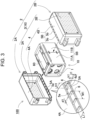
- FIGS. 2 and 3 are exploded perspective views of the battery pack shown in FIG. 1 .
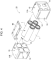
- FIG. 4 is an exploded perspective view of a battery unit of the battery pack shown in FIG. 2 .
- FIG. 5 is an enlarged cross-sectional view of an outer package case taken along line V-V shown in FIG. 1 .
- FIG. 6 is an enlarged cross-sectional view of the outer package case taken along line VI-VI shown in FIG. 1 .
- battery unit 10 including secondary battery cells is accommodated in outer package case 2.
- Battery unit 10 includes secondary battery cells 1 accommodated in battery holder 11 and arranged at predetermined positions.
- an outer shape of battery holder 11 is slightly smaller than an inner shape of outer package case 2 to be accommodated inside outer package case 2.
- FIG. 4 is an exploded perspective view of battery holder 11.
- Battery holder 11 holds secondary battery cells 1 and substrate 60.
- Battery holder 11 holding secondary battery cells 1 and substrate 60 constitutes battery unit 10.
- Substrate 60 is placed and fixed on a surface of battery holder 11.
- Battery holder 11 holds secondary battery cells 1.
- Battery holder 11 is divided into two sub-holders 11A and 11B, sandwiches secondary battery cells 1 in longitudinal directions of the cells, and holds secondary battery cells 1.
- Each of sub-holders 11A and 11B forms a cylindrical accommodating space 13 that accommodates secondary battery cell 1.
- four secondary battery cells 1 are stacked and held in a posture of two rows by two columns.
- the number of secondary battery cells 1 and the manner of stacking are not limited to this configuration, and three or less, or five or more secondary battery cells may be held.
- the invention is not limited to two stages, and the secondary battery cells may be stacked in one stage, that is, all the secondary battery cells may be arranged on the same surface, or three or more stages.
- the secondary battery cells may be alternately arranged in a staggered among the stages.
- the thickness of the battery holder can be reduced by setting the accommodating space to two stages and offsetting centers of the cylindrical shapes in the accommodating space in the upper and lower stages.
- Battery holder 11 is made of material, such as polycarbonate resin or ABS resin, with high insulation and heat resistance.
- Each of secondary battery cell 1 is a cylindrical secondary battery cell including an outer can with a cylindrical shape.
- the cylindrical secondary battery cell has electrode surfaces on both end surfaces thereof.
- a safety valve is provided on one electrode surface includes a safety valve.
- the safety valve is configured to open to release gas inside when an internal pressure of the outer can rises.
- the safety valve is often provided closer to the positive electrode, but in the invention, a position of the safety valve is not limited to be closer to the positive electrode, and may be another position, for example, closer to a negative electrode.
- Battery holder 11 has slits 14 configured to release the gas discharged from the safety valve to the outside of battery holder 11 when the safety valve is opened.
- a cylindrical lithium ion secondary battery may be suitably used as secondary battery cell 1.
- the secondary battery cell is not limited to the cylindrical battery or the lithium-ion secondary battery.
- the secondary battery cell all batteries that can be charged, for example, a nickel-metal hydride battery, a nickel-oxide battery, and the like can be used.
- a lead plate (not shown) is fixed to an end surface of secondary battery cell 1. Secondary battery cells 1 are connected in series or in parallel to one another with the lead plate.
- the lead plate is made of a metal plate and is welded to secondary battery cells 1.
- a lead positioning guide along an outer shape of the lead plate is formed on an inner surface of battery holder 11 to position the lead plate at a predetermined position.
- the lead plate may be closer to an outer surface of the battery holder rather than closer to an inner surface of the battery holder. In this case, after the secondary battery cell is inserted into the accommodating space of the battery holder, the lead plate is fixed to the electrode surface of the secondary battery cell exposed from the battery holder.
- An output of battery unit 10 constituted by secondary battery cells 1 connected in series or in parallel via the lead plates is output from battery pack 100.
- An upper surface of battery holder 11 is used as mounting surface 15 on which substrate 60 is mounted.
- a frame for holding substrate 60 may be formed on placement surface 15.
- a substrate holder for holding a substrate may be separately provided.
- Substrate 60 has electronic circuits mounted thereon.
- the electronic circuits may be a voltage detection circuit that detects a total potential or an intermediate potential of a battery assembly in which secondary battery cells 1 are connected in series or in parallel, a control circuit that controls charging and discharging, and a safety circuit.
- Substrate 60 is formed in a rectangular shape.
- Outer package case 2 accommodating battery unit 10 therein has a rectangular parallelepiped box shape.
- outer package case 2 is divided into first case 2A and second case 2B to sandwich battery unit 10 from the left and right to accommodate battery unit 10.
- a dividing direction in which first case 2A and second case 2B are divided perpendicularly crosses a direction in which battery holder 11 is divided into sub-holders 11A and 11B, thereby enhancing resistance to impact.
- first case 2A and second case 2B includes circumferential wall 4 provided around surface plate 3, and have a bottomed box shape with an opening in one side as a whole.
- First case 2A includes first surface plate 3A and first circumferential wall 4A provided around first surface plate 3A.
- Second case 2B includes second surface plate 3B and second circumferential wall 4B provided around second surface plate 3B.
- First circumferential wall 4A and second circumferential wall 4B have respective opening end portions coupled to each other to allow first case 2A and second case 2B to constitute a closed structure accommodating battery unit 10 therein.
- first case 2A and second case 2B shown in FIGS. 1 to 3 surface plate 3 is metal plate 16.
- First case 2A and second case 2B shown in the figures are opened at a bottom surface of the box shape, and openings are closed by metal plates 16 to form surface plates 3.
- Metal plate 16 has a lot of through-holes 17, and prevents a gas discharged from one of secondary battery cells 1 accommodated inside battery pack 100 from being ejected to the outside at a time, thereby preventing the flame from leaking to the outside of battery pack 100.
- Main bodies of first case 2A and second case 2B except for metal plates 16 are made of material having high insulating properties, for example, a resin such as polycarbonate or ABS.
- metal plates 16 are substantially entire surfaces of surface plates 3, and the metal plates may be partially provided on the surface plates, or the surface plates may be entirely made of resin without disposing the metal plates.
- overlap plates 5 are unitarily connected to circumferential walls 5 along respective opening ends of circumferential walls, overlap plates 5 are stacked inside and outside on each other.
- cross sections of circumferential walls 4 of first case 2A and second case 2B are substantially rectangular shapes.
- Overlap plates 5 are provided over entire circumferences of opening ends of circumferential walls 4.
- First overlap plate 5A stacked outside is connected to first circumferential wall 4A
- second overlap plate 5B stacked inside is connected to second circumferential wall 4B.
- first overlap plate 5A extends from the opening end of first case 2A toward first circumferential wall 4A, and is unitarily formed with first circumferential wall 4A to protrude from a tip end edge of first circumferential wall 4A along an extending direction in which circumferential walls 4 extend.
- First overlap plate 5A is thinner than first circumferential wall 4A, and has a stepped shape such that an outer surface of first overlap plate 5A is flush with an outer surface of first circumferential wall 4A, and an inner surface of first overlap plate 5A is lower than an inner surface of first circumferential wall 4A.
- first overlap plate 5A includes reinforcement ribs 6 protruding inward.
- Reinforcement ribs 6 shown in the figures are ridges unitarily formed with first overlap plate 5A, and extend from a tip end of first overlap plate 5A to tip end surface 4a of first circumferential wall 4A.
- First overlap plate 5A of the structure includes reinforcement ribs 6 protruding inward, so that a secondary moment of area in a cross section toward a bending direction is increased to prevent deformation in an outward direction.
- first overlap plate 5A is prevented from deforming in the outward direction, a flammable gas inside the battery pack is be safely released to the outside of the battery pack, and the gas is effectively prevented from being ejected to the outside at a time.
- Reinforcement ribs 6 shown in FIG. 5 are ridges having cross sections with rectangular shapes. Reinforcement ribs 6 having the shapes enhance the strength with a simple structure. However, the cross-sectional shapes of the reinforcement ribs are not limited to the rectangular shapes, and may be triangular shapes or shapes with distal end surfaces with curved shapes. Reinforcement rib 6 having a cross section with a rectangular shape is formed such that a distal end surface in a height direction (a lower end surface in FIG. 5 ) is flush with the inner surface of first circumferential wall 4A.
- first overlap plate 5A described above has thickness (t1) ranging from 0.5 mm to 1.5 mm, protruding amount (L1) from first circumferential wall 4A ranging from 1.5 mm to 5.0 mm, horizontal width (d1) of reinforcement rib 6 ranging from 0.2 mm to 1.0 mm, height (h1) ranging from 1.0 mm to 3.0 mm, center-to center distance (M1) of adjacent reinforcement ribs ranging from 3.0 mm to 5.0 mm, and total length (H1) of the reinforcement rib substantially equal to the protruding amount (L1) of first overlap plate 5A, thereby forming a shape reinforcing first overlap plate 5A.
- total length (H1) of the reinforcement rib may be shorter than protruding amount (L1) of first overlap plate 5A.
- second overlap plate 5B extends from the opening end of second case 2B toward second circumferential wall 4B, and is unitarily formed with second circumferential wall 4B to protrude from distal end surface 4b of second circumferential wall 4B along the extending direction in which circumferential walls 4 extend.
- Second overlap plate 5B is thinner than second circumferential wall 4B, and has a stepped shape in which an inner surface of second overlap plate 5B is flush with an inner surface of second circumferential wall 4B and an outer surface of second overlap plate 5B is lower than an outer surface of second circumferential wall 4B.
- Second overlap plate 5B includes fit portions 7 for guiding reinforcement ribs 6 provided on first overlap plate 5A.
- Fit portions 7 shown in the figures are slits 7A provided in second overlap plate 5B.
- Slits 7A shown in the figures extend from an end of second overlap plate 5B to the tip end surface of second circumferential wall 4B.
- Fit portions 7, which are slits 7A face reinforcement ribs 6 provided on first overlap plate 5A and have sizes and shapes to which reinforcement ribs 6 are fitted.
- second overlap plate 5B is divided into split plate portions 5b by slits 7A.
- Split plate portions 5b are thus fitted to fitting recesses 5a demarcated by reinforcement ribs 6 protruding toward the inner surface of first overlap plate 5A and tip end surface 4a of first circumferential wall 4A, and are connected at predetermined positions. That is, in first case 2A and second case 2B, by guiding reinforcement ribs 6 provided on the inner surface of first overlap plate 5A to fit portions 7 provided in second overlap plate 5B and guiding split plate portions 5b of second overlap plate 5B to fitting recesses 5a of first overlap plate 5A, the opening end portions of first case 2A and second case 2B are reliably connected to each other by the fitting structure.
- first overlap plate 5A As shown in FIGS. 3 and 6 , a corner between the tip end surface and the inner side surface and a corner between the tip end surface and the upper end surface of each reinforcement rib 6 are chamfered.
- second overlap plate 5B as shown in FIGS. 2 and 6 , an opening edge portion of each slit 7A and a corner between the tip end surface and the inner side surface are chamfered.
- This configuration reduces a contact between first overlap plate 5A and second overlap plate 5B at the time of connecting first case 2A and second case 2B, and facilitate split plate portions 5b of second overlap plate 5B to be easily guided to fitting recesses 5a of first overlap plate 5A, and reinforcement ribs 6 are easily fitted to slits 7a.
- first overlap plate 5A including reinforcement ribs 6 may be connected by the fitting structure.
- thickness (t2) may be equal to height (h1) of reinforcement ribs 6, protruding amount (L2) from second circumferential wall 4B may be equal to protruding amount (L1) of first overlap plate 5A, horizontal width (d2) of slits 7A may be slightly larger than horizontal width (d1) of reinforcement ribs 6, and total length (H2) of each slit 7A may be equal to total length (H1) of each reinforcement rib 6.
- thickness (t1) of first overlap plate 5A is equal to thickness (t2) of second overlap plate 5B, which is approximately 1/2 of thicknesses (s) of circumferential walls 4.
- thickness (t1+t2) of a stacked portion is equal to thicknesses (s) of circumferential walls 4.
- the first overlap plate and the second overlap plate do not necessarily have the same thickness, and may have different thicknesses.
- the first overlap plate may be thicker than the second overlap plate.
- the thicker first overlap plate effectively prevents deformation of the first overlap plate in the outward direction when a gas pressure in the outer package case increases. Even when the first overlap plate and the second overlap plate have different thicknesses, thickness (t1+t2) of a stacked portion of the first overlap plate and the second overlap plate is preferably equal to the thicknesses (s) of the circumferential walls.
- First overlap plate 5A and second overlap plate 5B shown in the drawings are formed such that the thickness from a distal end thereof to a proximal end thereof is constant. However, as shown in FIG. 7 , first overlap plate 5A and second overlap plate 5B may be thinner from the proximal end toward the distal end.
- This structure provides an advantageous effect that a distal end of each of split plate portions 5b of second overlap plate 5B, which are to be inserted to fitting recesses 5a formed in first overlap plate 5A, can be thin while the depth of a distal end of each of fitting recessed portions 5a is increased, and thus first overlap plate 5A and second overlap plate 5B can be smoothly connected when first overlap plate 5A and second overlap plate 5B are fitted to each other from the tip ends.
- first overlap plate 5A and second overlap plate 5B are stacked on each other and connected to each other by guiding reinforcement ribs 6 on first overlap plate 5A with slits 7A provided in second overlap plate 5B.
- height (h1) of reinforcement ribs 6 may be equal to thickness (t2) of the second overlap plate. Accordingly, distal end surfaces of reinforcement ribs 6 may be flush with the inner surface of second overlap plate 5B connected to each other, thus allowing an inner surface of the stacked portion to be flat.
- heights (h1) of reinforcement ribs 6 may be larger than thickness (t2) of second overlap plate 5B. This structure further increases the strength of first overlap plate 5A.
- fit portions 7 of second overlap plate 5B are slits 7A, and the fit portions formed in the second overlap plate may be grooves.
- second overlap plate 5B of second case 2B has grooves 7B provided at positions facing reinforcement ribs 6 provided on first overlap plate 5A of first case 2A to form fit portions 7.
- Grooves 7B shown in the figures extend from the distal end of second overlap plate 5B to end surface 4a of second circumferential wall 4B, and has sizes and shapes fit to reinforcement ribs 6 provided on first overlap plate 5A.
- Depths (h2) of grooves 7B are smaller than thickness (t2) of second overlap plate 5B and substantially equal to heights (h1) of reinforcement ribs 6 of first overlap plate 5A.
- Reinforcement ribs 6 formed on first overlap plate 5A are lower than reinforcement ribs 6 shown in FIG. 3 described above, and are formed such that distal end surfaces of reinforcement ribs 6 are lower than the inner surface of first circumferential wall 4A.
- fit portions 7 are grooves 7B provides an advantageous effect that second overlap plate 5B has a unitarily-connected structure without dividing second overlap plate 5B into pieces, and first overlap plate 5A can be reinforced by reinforcement ribs 6 while fitting reinforcement ribs 6 of first overlap plate 5A to grooves 7B by the fitting structure.
- Outer package case 2 described above has a structure in which first overlap plate 5A is reinforced by reinforcement ribs 6 to prevent deformation due to the gas discharged from secondary battery cells 1 accommodated in outer package case 2.
- the reinforcement ribs may be provided on the second overlap plate.
- second overlap plate 5B of second case 2B includes second reinforcement ribs 8 protruding inward.
- First case 2A shown in the figures has the same structure as first case 2A shown in FIGS. 1 to 4 described above.
- Second case 2B also has the same structure as that of second case 2B shown in FIGS. 1 to 4 , except that second reinforcement ribs 8 are provided on inner surface of second overlap plate 5B.
- second reinforcement ribs 8 are unitarily formed on the inner surface of second overlap plate 5B.
- Second reinforcement ribs 8 are positioned at center portions of split plate portions 5b divided by fit portions 7 which are slits 7A, and extend from the opening end of second case 2B toward second circumferential wall 4B.
- Second reinforcement ribs 8 shown in the figures have total length (H3) extending from the distal end of second overlap plate 5B to an end portion of second circumferential wall 4B beyond a proximal end of second overlap plate 5B, which is larger than protruding amount (L2) of second overlap plate 5B.
- Second reinforcement ribs 8 extend from second overlap plate 5B to second circumferential wall 4B more effectively prevents the deformation of second overlap plate 5B.
- Second reinforcement ribs 8 shown in the figures are ridges having cross sections with semicircular shapes. Second reinforcement ribs 8 having the shape provide an advantageous effect to reliably reinforce second overlap plate 5B while maintaining a preferably contact with battery unit 10 or the like accommodated in outer package case 2.
- Second overlap plate 5B described above includes second reinforcement ribs 8 protruding inward, so that the secondary moment of area in a cross section can be increased to prevent the deformation against the gas pressure. Therefore, even when the gas is discharged from one of secondary battery cells 1 accommodated inside outer package case 2, first overlap plate 5A and second overlap plate 5B are prevented from deforming in the outward direction, and the fitting connection portion of the outer package case can be more effectively prevented from being broken.
- Outer package case 2 may have a structure shown in FIGS. 12 to 14 .
- reinforcement ribs 6 are provided on the inner surface of first overlap plate 5A of first case 2A, and fit portions 7 which are slits 7A for guiding reinforcement ribs 6 of first overlap plate 5A are provided in second overlap plate 5B of second case 2B.
- Second reinforcement ribs 8 are provided on the outer surface of second overlap plate 5B of second case 2B, and second fit portions 9 which are slits 9A for guiding second reinforcement ribs 8 provided on second overlap plate 5B is provided in first overlap plate 5A of first case 2A.
- second reinforcement ribs 8 are unitarily formed with second overlap plate 5B and protrude from center portions of outer surfaces of split plate portions 5b divided by fit portions 7 which are slits 7A and extending from distal end surfaces of split plate portions 5b to distal end surface 4b of second circumferential wall 4B.
- Second reinforcement ribs 8 provided on second overlap plate 5B may have the same shapes and sizes as reinforcement ribs 6 provided on first overlap plate 5A.
- First overlap plate 5A is divided into split plate portions 5c by fit portions 9 which are slits 9A, and is formed such that reinforcement ribs 6 protrude from center portions of inner side surfaces of split plate portions 5c.
- Second fit portions 9 which are slits 9A provided in first overlap plate 5A may have the same shapes and sizes as fit portions 7 which are slits 7A provided in second overlap plate 5B.
- First case 2A and second case 2B of the structure are connected to each other by guiding reinforcement ribs 6 of first overlap plate 5A to fit portions 7 of second overlap plate 5B and guiding second reinforcement ribs 8 of second overlap plate 5B to second fit portions 9 of first overlap plate 5A.
- split plate portions 5b obtained by dividing second overlap plate 5B are guided to fitting recesses 5a of first overlap plate 5A
- split plate portions 5c obtained by dividing first overlap plate 5A are guided to fitting recesses 5d formed between second reinforcement ribs 8 on an outer surface of second overlap plate 5B.
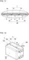
- first overlap plate 5A As shown in FIG. 12 , in outer package case 2, on an outer surface of first case 2A, second reinforcement ribs 8 are exposed from second fit portions 9 which are slits 9A formed in first overlap plate 5A.
- height (h3) of second reinforcement ribs 8 is equal to thickness (t1) of first overlap plate 5A. Accordingly, the outer surface of first overlap plate 5A is flush with an upper surface which is outer side surfaces of second reinforcement ribs 8 connected to each other, and an outer side surface of a stacked portion has a planar shape, thereby enhancing the touch feeling while providing a beautiful appearance.
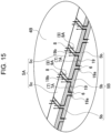
- fit portions 7 provided in second overlap plate 5B and second fit portions 9 provided in first overlap plate 5A are slits 7A and 9A. As shown in FIGS. 14 and 15 , while first overlap plate 5A are stacked on second overlap plate 5B, meandering flow path 19 is formed between fit portion 7 and second fit portion 9 adjacent to each other.
- Meandering flow path 19 is configured to allow gas to pass from the inside to the outside of outer package case 2
- Meandering flow path 19 is a flow path of a gas formed between first overlap plate 5A and second overlap plate 5B stacked on each other, and configured to allows a gas flowing in from a position between reinforcement ribs 6 and slits 7A formed closer to an inner surface of second overlap plate 5B to pass through between stacked surfaces of second overlap plate 5B and first overlap plate 5A to flow from a position between second reinforcement rib 8 and slits 9A formed in an outer surface of first overlap plate 5A to the outside.
- Meandering flow path 19 is not necessarily opened, but when an abnormality occurs in one of accommodated secondary battery cells 1 and a high-temperature and high-pressure gas is discharged to increase the internal pressure, the gas passes from the inside to the outside of outer package case 2 to be discharged. In this way, a lot of meandering flow paths 19 are gaps formed narrow as much as possible between first overlap plate 5A and second overlap plate 5B stacked and fit to each other and have long planar distances, and are configured to allow the gas to pass through meandering flow paths 19. This configuration safely discharges the gas inside while reducing a discharge amount without discharging the gas at a time.
- fit portions 7 and second fit portions 9 are slits 7A and 9A and a total length of inflow portions 19a and outflow portions 19b of meandering flow paths 19 formed in the inner surface and the outer surface of overlap plates 5 is long. This configuration controls the passage resistance of the gas and allows the gas in outer package case 2 to be safely discharged to the outside.
- the cross sections of the circumferential walls of first case 2A and second case 2B have substantially rectangular shapes, and reinforcement ribs 6 and fit portions 7 are provided only on overlap plates 5 located on portions of circumferential walls 4 at the long sides of the rectangular shape.
- This structure effectively prevents the fitting connection portion of outer package case 2 from breaking since first overlap plate 5A is reinforced with reinforcement ribs 6 on the long side, which is easier to deform than the short side of the rectangular shape.
- the reinforcement ribs and the fit portions may be further provided on the overlap plates positioned on the short sides of the circumferential walls having a rectangular shape. This structure effectively prevents the fitting connection portion of the outer package case from breaking since the first overlap plate is reinforced by the reinforcement ribs over the entire peripheries of the circumferential walls.
- a battery pack according to the invention is suitably used as a power supply of a portable electric device such as an electric cleaner or an electric power tool.
- the invention can be appropriately used for applications such as a power supply device for a movable body such as a power-assisted bicycle or an electric cart.
Landscapes
- Chemical & Material Sciences (AREA)
- Chemical Kinetics & Catalysis (AREA)
- Electrochemistry (AREA)
- General Chemical & Material Sciences (AREA)
- Battery Mounting, Suspending (AREA)
Abstract
Description
- The present invention relates to a battery pack.
- A battery pack including a lot number of secondary battery cells connected in series or parallel to one another is used as a power supply for a portable electric device such as an electric cleaner or an electric power tool, or a backup power supply for a server, home, office, or factory power supply device for stationary storage, and is further used in a driving power supply of a power-assisted bicycle, a driving power supply of an electric scooter, an electric cart, or a vehicle such as a hybrid vehicle or an electric automatic vehicle. Lithium-ion secondary batteries are often used as the secondary battery cells used in such a battery pack, and the lithium-ion secondary batteries may lead to an unsafe event involving smoke or fire due to some abnormality such as penetration of a bolt during a collision. Suppose an unsafe event occurs in the battery pack, fire from the secondary battery cells inside the battery pack may be released to the outside of the battery pack.
- In such a battery pack, a structure is adopted in which a battery unit including secondary battery cells is accommodated in an outer package case made of resin. The outer package case often adopts a structure in which a first case and a second case, each of which has a box shape and is provided with a circumferential wall around a bottom plate, are connected to each other through an opening. For example, such an outer package case has a fitting structure in which step portions each having a thin thickness are provided on an inner side surface of an opening of one case and an outer side surface of an opening of the other case, and which is connected by a stacked portion obtained by fitting the step portions to each other and stacking. (
PTLs 1 and 2) The structure allows the first case and the second case to be accurately connected while the thickness of the stacked part of the first case and the second case is the same as that of the other circumferential wall portion. - However, in a pack battery including such an outer package case, when an abnormality such as thermal runaway occurs in accommodated secondary battery cells and a high-temperature and high-pressure gas is released, the inside of the outer package case is filled with the gas. As indicated by an arrow shown in
FIG. 16 ,flow path 94 connecting fromfitting connection portion 93 ofouter package case 92 to the outside is generated, and the high-temperature and high-pressure gas may be injected fromflow path 94 to the outside of the case, then developing to fire and accompanying leakage fire. In particular, infitting connection portion 93 of the outer package case, stackedportions 95 are formed to be thin. Therefore, when the high-pressure gas passes through a boundary offitting connection portion 93, as indicated by a chain line shown inFIG. 16 , outer stackedportion 95 easily deforms in an outward direction by a gas pressure, so that a large amount of flammable gas may be released to the outside at a time, which causes fire. Therefore, in the battery pack in related art, in order to prevent fire from the fitting connection portion of the outer package case, it is necessary to reinforce the fitting connection portion with an expensive refractory sheet or the like. -
- PTL 1:
Japanese Patent Laid-Open Publication No. 07-10591 - PTL 2:
Japanese Patent Laid-Open Publication No. 10-241647 - The invention is developed to solve the above problems, and one object of the invention is to provide a battery pack capable of safely releasing a flammable gas inside the battery pack to the outside of the battery pack while preventing breakage of a fitting connection portion of a case due to an increase in internal pressure of the battery pack caused by a gas discharged due to a battery abnormality, thereby improving the safety.
- A battery pack according to a first aspect of the invention includes a battery unit and an outer package case accommodating the battery unit therein. The outer package case includes: a first case including a first surface plate and a first circumferential wall provided around the first surface plate; and a second case including a second surface plate and a second circumferential wall provided around the second surface plate. The first circumferential wall and the second circumferential wall have respective opening end portions coupled to each other to allow the first case and the second case to constitute a closed structure accommodating the battery unit therein. Overlap plates are unitarily connected to the first circumferential wall and the second circumferential wall along respective opening ends of the first circumferential wall and the second circumferential wall, the overlap plates being stacked inside and outside on each other. A first overlap plate out of the overlap plates is connected to the first circumferential wall at the outer side. A second overlap plate out of the second overlap plates is connected to the second circumferential wall at the inner side. The first overlap plate includes reinforcement ribs which extend from an opening end of the first overlap plate toward the first circumferential wall and which protrude inward. The second overlap plate includes fit portions therein which are slits or grooves configured to guide the reinforcement ribs. The first case and the second case are connected to each other such that by the fit portions guide the reinforcement ribs to stack the first overlap plate on the second overlap plate.
- The above configuration provides an advantageous effect that even in a state where the internal pressure of the outer package case increases by a gas discharged due to a battery abnormality, the breakage of the fitting connection portion of the case is prevented, and the flammable gas inside the battery pack is safely released to the outside of the battery pack, thus enhancing safety. This is because, in the battery pack described above, the first case and the second case are connected to each other by stacking the first overlap plate connected to the first circumferential wall of the first case and the second overlap plate connected to the second circumferential wall of the second case on each other, and the first case and the second case are connected to each other by providing, the reinforcement ribs protrudes inward on the first overlap plate stacked outside, and the second overlap plate stacked inside includes the fit portions which are slits or grooves for guiding the reinforcement ribs to the fit portions, to guide the reinforcement ribs with the fit portions and stack the first overlap plate on the second overlap plate. This structure increases the rigidity of the first overlap plate and prevent deformation outward due to the gas pressure by providing the reinforcement ribs on an inner surface of the first overlap plate stacked outside. Therefore, in a state where the internal pressure of the outer package case is increased, the flammable gas in the case is prevented from breaking the fitting connection portion and being discharged to the outside at a time, which can effectively prevent a flame from leaking to the outside. The fit portions of the reinforcement ribs in the second overlap plate guide the reinforcement ribs to allow the first overlap plate and the second overlap plate to be connected by a fitting structure. Therefore, the first overlap plate is reinforced while appropriately connecting the first overlap plate to the second overlap plate without increasing the thickness of a part in which the first overlap plate and the second overlap plate are stacked on each other.
- In a battery pack according to a second aspect of the invention, the fit portions are the slits, and heights of the reinforcement ribs are equal to a thickness of the second overlap plate. This configuration allows the first overlap plate to be fit to the second overlap plate reliably while distal end surfaces of the reinforcement ribs of the first overlap plate are flush with an inner surface of the second overlap plate and the inner side surface of the case has a planar shape.
- In a battery pack according to a third aspect of the invention, the second overlap plate includes second reinforcement ribs which extend from an opening end of the second overlap plate toward the second circumferential wall and which protrude outward. The first overlap plate includes second fit portions therein which are slits or grooves configured to guide the second reinforcement ribs. The first case and the second case are connected to each other such that the second fit portions guide the second reinforcement ribs to stack the first overlap plate on the second overlap plate.
- In to the above configuration, the second reinforcement ribs are provided on the second overlap plate in addition to the reinforcement ribs on the first overlap plate, This configuration increases the rigidity of both the first overlap plate and the second overlap plate to more effectively prevent the overlap plates from deforming in an outward direction due to the gas pressure and the fitting connection portion from being broken. Therefore, when the internal pressure of the outer package case increases, the flammable gas inside the battery pack is released to the outside of the battery pack more and effectively prevent the flame from leaking to the outside. The second fit portions in the first overlap plate connect the reinforcement ribs and the second reinforcement ribs to the fit portions and the second fit portions while being fitted to the fit portions and the second fit portions, respectively. Therefore, the first overlap plate and the second overlap plate are reinforced while appropriately connecting the first overlap plate to the second overlap plate without increasing the thickness of a stacked part of the first overlap plate and the second overlap plate.
- In a battery pack according to a fourth aspect of the invention, the second fit portions are slits, and heights of the second reinforcement ribs is equal to a thickness of the first overlap plate. In the above configuration, distal end surface of the second reinforcement ribs is flush with the outer surface of the first overlap plate while forming a structure in which the second reinforcement ribs are disposed in the slits provided in the first overlap plate to be exposed, the touch feeling can be improved while improving the appearance.
- In a battery pack according to a fifth aspect of the invention, the fit portions are the slits and the second fit portions are the slits. Each fit portion out of the fit portions and a corresponding one second fit portion of the second fit portions adjacent to each other form a meandering flow path between the each fit portion and the corresponding one second fit portion. The meandering flow path is configured to passes from an inside of the outer package case to an outside of the outer package case through the meandering flow path. In the above configuration, in a state where the reinforcement ribs are fitted to the slits provided in the second overlap plate and the second reinforcement ribs are fitted to the slits provided in the first overlap plate, the meandering flow path through which the gas passes is formed between the fit portion and the second fit portion adjacent to each other. Therefore, a gas filling the outer package case due to a battery abnormality is discharged smoothly outside the outer package case via meandering flow paths formed in the overlap plates. In particular, since the fit portions and the second fit portions are slits, a total length of an inflow portion and an outflow portion of the meandering flow paths formed in the inner surface and the outer surface of the overlap plate can be increased, and the gas in the outer package case can be safely discharged to the outside. Accordingly, it is possible to effectively prevent the flame from leaking to the outside by preventing a discharge amount of the high-temperature gas discharged to the outside of the outer package case.
- In a battery pack according to a sixth aspect of the invention, the second overlap plate includes reinforcement ribs which extend from an opening end the second overlap plate toward the second circumferential wall and which protrude inward. The first case and the second case are connected to each other such that the first overlap plate is stacked on the second overlap plate.
- In the above configuration, the second reinforcement ribs are provided on the second overlap plate in addition to the reinforcement ribs on the first overlap plate. This configuration increases the rigidity of both the first overlap plate and the second overlap plate to effectively prevent the overlap plates from deforming in an outward direction due to the gas pressure and the fitting connection portion from being broken. Therefore, when the internal pressure of the outer package case increases, the flammable gas inside the battery pack is safely released to the outside of the battery pack more and the flame is effectively prevented from leaking to the outside. Since the second fit portions protrude from an inner side surface of the second overlap plate, it is possible to reduce the influence of the second reinforcement ribs provided on the second overlap plate on the first overlap plate.
- In a battery pack according to a seventh aspect of the invention, thicknesses of the first overlap plate and the second overlap plate are 1/2 of a thickness of the circumferential walls. The above configuration allows an inner surface and an outer surface of the stacked part to be flush with a surface of the circumferential wall by determining the thickness of the stacked part of the first overlap plate and the second overlap plate to be equal to the thicknesses of the circumferential walls while realizing a stable connection state by making the thicknesses of the first overlap plate and the second overlap plate equal.
- In a battery pack according to an eighth aspect of the invention, cross sections of the circumferential walls of the first case and the second case have rectangular shapes, and the overlap plates are provided over entire circumferences of opening ends of the circumferential walls. The reinforcement ribs and the fit portions are provided at portions of the overlap plates located on long sides of the rectangular shapes of the circumferential walls.
- In the above configuration, the reinforcement ribs and the fit portions are provided at portions of the overlap plates located on long sides of the first case and the second case of which the cross-sectional shapes of the circumferential walls are rectangular shape. The circumferential walls on the long sides deforming easily than short sides are reinforced with the reinforcement ribs to effectively prevent the breakage of the fitting connection portion of the outer package case.
-
-
FIG. 1 is a perspective view of a battery pack according toExemplary Embodiment 1 of the invention. -
FIG. 2 is a partially enlarged exploded perspective view of the battery pack shown inFIG. 1 when viewed from left. -
FIG. 3 is a partially enlarged exploded perspective view of the battery pack shown inFIG. 1 when viewed from right. -
FIG. 4 is an exploded perspective view of a battery unit of the battery pack shown inFIG. 2 . -
FIG. 5 is an enlarged cross-sectional view of the battery pack taken along a line V-V shown inFIG. 1 . -
FIG. 6 is an enlarged exploded cross-sectional view of the battery pack taken along a line VI-VI shown inFIG. 1 . -
FIG. 7 is an enlarged exploded cross-sectional view of another example of overlap plates of an outer package case. -
FIG. 8 is a partially enlarged exploded perspective view of the outer package case of the battery pack according toexemplary Embodiment 2 of the invention. -
FIG. 9 is an enlarged cross-sectional view of the outer package case of the battery pack according toEmbodiment 2 of the invention. -
FIG. 10 is a partially enlarged exploded perspective view of the outer package case of the battery pack according toExemplary Embodiment 3 of the invention. -
FIG. 11 is an enlarged cross-sectional view of the outer package case of the battery pack according toEmbodiment 3 of the invention. -
FIG. 12 is a perspective view of the battery pack according toexemplary Embodiment 4 of the invention. -
FIG. 13 is a partially enlarged exploded perspective view of the outer package case of the battery pack shown inFIG. 12 . -
FIG. 14 is an enlarged cross-sectional view of the outer package case of the battery pack shown inFIG. 12 . -
FIG. 15 is a cross-sectional perspective view of the battery pack shown inFIG. 12 while the battery pack discharges a gas from the inside to the outside of the outer package case. -
FIG. 16 is an enlarged cross-sectional perspective view of a conventional battery pack for showing a state where a fitting connection portion of an outer package case of the conventional battery pack breaks. - Exemplary embodiments of the invention will be described below with reference to the drawings. The embodiments described below are examples for embodying a technical idea of the invention, and the invention is not limited to the following. The present specification does not specify members described in the claims as members in the embodiments. In particular, dimensions, materials, shapes, relative arrangements, and the like of components to be described in the embodiments are not intended to limit the scope of the invention unless particularly specified, and are merely illustrative examples. Sizes, positional relations, and the like of the members shown in the drawings may be exaggerated to clarify the description. In the following description, the same names and reference numerals denote the same or similar members, and detailed description thereof is omitted as appropriate. Regarding each element constituting the invention, an aspect may be implemented in which a plurality of elements are constituted by the same member and the plurality of elements are shared by one member, or conversely, functions of one member may be assigned and implemented by a plurality of members.
- A battery pack according to the invention is used as a power supply for a portable electric device such as an electric cleaner or an electric power tool, or a backup power supply for server, home, office, or factory power supply device for stationary storage, and is further used in a driving power supply of a power-assisted bicycle, a driving power supply of an electric scooter, an electric cart, or a vehicle such as a hybrid vehicle or an electric automatic vehicle. A battery pack used as the power supply for a portable electric device will be described as an embodiment according to the invention below.
-
Battery pack 100 according toExemplary Embodiment 1 of the present invention is shown inFIGS. 1 to 5 .FIG. 1 is an external perspective view of the battery pack.FIGS. 2 and3 are exploded perspective views of the battery pack shown inFIG. 1 .FIG. 4 is an exploded perspective view of a battery unit of the battery pack shown inFIG. 2 .FIG. 5 is an enlarged cross-sectional view of an outer package case taken along line V-V shown inFIG. 1 .FIG. 6 is an enlarged cross-sectional view of the outer package case taken along line VI-VI shown inFIG. 1 . Inbattery pack 100 shown in the figures,battery unit 10 including secondary battery cells is accommodated inouter package case 2. -
Battery unit 10 includessecondary battery cells 1 accommodated inbattery holder 11 and arranged at predetermined positions. Inbattery unit 10, an outer shape ofbattery holder 11 is slightly smaller than an inner shape ofouter package case 2 to be accommodated insideouter package case 2.FIG. 4 is an exploded perspective view ofbattery holder 11.Battery holder 11 holdssecondary battery cells 1 andsubstrate 60.Battery holder 11 holdingsecondary battery cells 1 andsubstrate 60 constitutesbattery unit 10.Substrate 60 is placed and fixed on a surface ofbattery holder 11. -
Battery holder 11 holdssecondary battery cells 1.Battery holder 11 is divided into twosub-holders secondary battery cells 1 in longitudinal directions of the cells, and holdssecondary battery cells 1. Each of sub-holders 11A and 11B forms a cylindricalaccommodating space 13 that accommodatessecondary battery cell 1. In the example, foursecondary battery cells 1 are stacked and held in a posture of two rows by two columns. The number ofsecondary battery cells 1 and the manner of stacking are not limited to this configuration, and three or less, or five or more secondary battery cells may be held. The invention is not limited to two stages, and the secondary battery cells may be stacked in one stage, that is, all the secondary battery cells may be arranged on the same surface, or three or more stages. Other than the matrix arrangement, the secondary battery cells may be alternately arranged in a staggered among the stages. For example, the thickness of the battery holder can be reduced by setting the accommodating space to two stages and offsetting centers of the cylindrical shapes in the accommodating space in the upper and lower stages.Battery holder 11 is made of material, such as polycarbonate resin or ABS resin, with high insulation and heat resistance. - Each of
secondary battery cell 1 is a cylindrical secondary battery cell including an outer can with a cylindrical shape. The cylindrical secondary battery cell has electrode surfaces on both end surfaces thereof. A safety valve is provided on one electrode surface includes a safety valve. The safety valve is configured to open to release gas inside when an internal pressure of the outer can rises. The safety valve is often provided closer to the positive electrode, but in the invention, a position of the safety valve is not limited to be closer to the positive electrode, and may be another position, for example, closer to a negative electrode.Battery holder 11 hasslits 14 configured to release the gas discharged from the safety valve to the outside ofbattery holder 11 when the safety valve is opened. - A cylindrical lithium ion secondary battery may be suitably used as
secondary battery cell 1. However, in the battery pack according to the invention, the secondary battery cell is not limited to the cylindrical battery or the lithium-ion secondary battery. As the secondary battery cell, all batteries that can be charged, for example, a nickel-metal hydride battery, a nickel-oxide battery, and the like can be used. - A lead plate (not shown) is fixed to an end surface of
secondary battery cell 1.Secondary battery cells 1 are connected in series or in parallel to one another with the lead plate. The lead plate is made of a metal plate and is welded tosecondary battery cells 1. A lead positioning guide along an outer shape of the lead plate is formed on an inner surface ofbattery holder 11 to position the lead plate at a predetermined position. The lead plate may be closer to an outer surface of the battery holder rather than closer to an inner surface of the battery holder. In this case, after the secondary battery cell is inserted into the accommodating space of the battery holder, the lead plate is fixed to the electrode surface of the secondary battery cell exposed from the battery holder. An output ofbattery unit 10 constituted bysecondary battery cells 1 connected in series or in parallel via the lead plates is output frombattery pack 100. - An upper surface of
battery holder 11 is used as mountingsurface 15 on whichsubstrate 60 is mounted. A frame for holdingsubstrate 60 may be formed onplacement surface 15. Alternatively, a substrate holder for holding a substrate may be separately provided. -
Substrate 60 has electronic circuits mounted thereon. The electronic circuits may be a voltage detection circuit that detects a total potential or an intermediate potential of a battery assembly in whichsecondary battery cells 1 are connected in series or in parallel, a control circuit that controls charging and discharging, and a safety circuit.Substrate 60 is formed in a rectangular shape. -
Outer package case 2accommodating battery unit 10 therein has a rectangular parallelepiped box shape. In the example shown inFIG. 1 ,outer package case 2 is divided intofirst case 2A andsecond case 2B tosandwich battery unit 10 from the left and right to accommodatebattery unit 10. A dividing direction in whichfirst case 2A andsecond case 2B are divided perpendicularly crosses a direction in whichbattery holder 11 is divided into sub-holders 11A and 11B, thereby enhancing resistance to impact. - Each of
first case 2A andsecond case 2B includescircumferential wall 4 provided aroundsurface plate 3, and have a bottomed box shape with an opening in one side as a whole.First case 2A includesfirst surface plate 3A and firstcircumferential wall 4A provided aroundfirst surface plate 3A.Second case 2B includessecond surface plate 3B and secondcircumferential wall 4B provided aroundsecond surface plate 3B. Firstcircumferential wall 4A and secondcircumferential wall 4B have respective opening end portions coupled to each other to allowfirst case 2A andsecond case 2B to constitute a closed structure accommodatingbattery unit 10 therein. - In
first case 2A andsecond case 2B shown inFIGS. 1 to 3 ,surface plate 3 ismetal plate 16.First case 2A andsecond case 2B shown in the figures are opened at a bottom surface of the box shape, and openings are closed bymetal plates 16 to formsurface plates 3.Metal plate 16 has a lot of through-holes 17, and prevents a gas discharged from one ofsecondary battery cells 1 accommodated insidebattery pack 100 from being ejected to the outside at a time, thereby preventing the flame from leaking to the outside ofbattery pack 100. Main bodies offirst case 2A andsecond case 2B except formetal plates 16 are made of material having high insulating properties, for example, a resin such as polycarbonate or ABS. Inouter package case 2 shown in the figured,metal plates 16 are substantially entire surfaces ofsurface plates 3, and the metal plates may be partially provided on the surface plates, or the surface plates may be entirely made of resin without disposing the metal plates. - In
first case 2A andsecond case 2B shown inFIGS. 2 and3 ,overlap plates 5 are unitarily connected tocircumferential walls 5 along respective opening ends of circumferential walls,overlap plates 5 are stacked inside and outside on each other. Inouter package case 2 shown in the figures, cross sections ofcircumferential walls 4 offirst case 2A andsecond case 2B are substantially rectangular shapes.Overlap plates 5 are provided over entire circumferences of opening ends ofcircumferential walls 4.First overlap plate 5A stacked outside is connected to firstcircumferential wall 4A, andsecond overlap plate 5B stacked inside is connected to secondcircumferential wall 4B. - As shown in
FIG. 3 ,first overlap plate 5A extends from the opening end offirst case 2A toward firstcircumferential wall 4A, and is unitarily formed with firstcircumferential wall 4A to protrude from a tip end edge of firstcircumferential wall 4A along an extending direction in whichcircumferential walls 4 extend.First overlap plate 5A is thinner than firstcircumferential wall 4A, and has a stepped shape such that an outer surface offirst overlap plate 5A is flush with an outer surface of firstcircumferential wall 4A, and an inner surface offirst overlap plate 5A is lower than an inner surface of firstcircumferential wall 4A. In order to increase the strength offirst overlap plate 5A thinner thancircumferential wall 4,first overlap plate 5A includesreinforcement ribs 6 protruding inward.Reinforcement ribs 6 shown in the figures are ridges unitarily formed withfirst overlap plate 5A, and extend from a tip end offirst overlap plate 5A to tipend surface 4a of firstcircumferential wall 4A.First overlap plate 5A of the structure includesreinforcement ribs 6 protruding inward, so that a secondary moment of area in a cross section toward a bending direction is increased to prevent deformation in an outward direction. Therefore, even in a state where a gas is discharged from one ofsecondary battery cells 1 accommodated inouter package case 2 and the gas passes from a boundary portion betweenfirst overlap plate 5A andsecond overlap plate 5B to the outside,first overlap plate 5A is prevented from deforming in the outward direction, a flammable gas inside the battery pack is be safely released to the outside of the battery pack, and the gas is effectively prevented from being ejected to the outside at a time. -
Reinforcement ribs 6 shown inFIG. 5 are ridges having cross sections with rectangular shapes.Reinforcement ribs 6 having the shapes enhance the strength with a simple structure. However, the cross-sectional shapes of the reinforcement ribs are not limited to the rectangular shapes, and may be triangular shapes or shapes with distal end surfaces with curved shapes.Reinforcement rib 6 having a cross section with a rectangular shape is formed such that a distal end surface in a height direction (a lower end surface inFIG. 5 ) is flush with the inner surface of firstcircumferential wall 4A. - As shown in a partially enlarged view shown in
FIG. 3 and an exploded cross-sectional view shown inFIG. 6 ,first overlap plate 5A described above has thickness (t1) ranging from 0.5 mm to 1.5 mm, protruding amount (L1) from firstcircumferential wall 4A ranging from 1.5 mm to 5.0 mm, horizontal width (d1) ofreinforcement rib 6 ranging from 0.2 mm to 1.0 mm, height (h1) ranging from 1.0 mm to 3.0 mm, center-to center distance (M1) of adjacent reinforcement ribs ranging from 3.0 mm to 5.0 mm, and total length (H1) of the reinforcement rib substantially equal to the protruding amount (L1) offirst overlap plate 5A, thereby forming a shape reinforcingfirst overlap plate 5A. However, total length (H1) of the reinforcement rib may be shorter than protruding amount (L1) offirst overlap plate 5A. - As shown in
FIG. 2 ,second overlap plate 5B extends from the opening end ofsecond case 2B toward secondcircumferential wall 4B, and is unitarily formed with secondcircumferential wall 4B to protrude fromdistal end surface 4b of secondcircumferential wall 4B along the extending direction in whichcircumferential walls 4 extend.Second overlap plate 5B is thinner than secondcircumferential wall 4B, and has a stepped shape in which an inner surface ofsecond overlap plate 5B is flush with an inner surface of secondcircumferential wall 4B and an outer surface ofsecond overlap plate 5B is lower than an outer surface of secondcircumferential wall 4B.Second overlap plate 5B includesfit portions 7 for guidingreinforcement ribs 6 provided onfirst overlap plate 5A.Fit portions 7 shown in the figures areslits 7A provided insecond overlap plate 5B.Slits 7A shown in the figures extend from an end ofsecond overlap plate 5B to the tip end surface of secondcircumferential wall 4B.Fit portions 7, which areslits 7A,face reinforcement ribs 6 provided onfirst overlap plate 5A and have sizes and shapes to whichreinforcement ribs 6 are fitted. - As shown in
FIG. 2 ,second overlap plate 5B is divided intosplit plate portions 5b byslits 7A.Split plate portions 5b are thus fitted tofitting recesses 5a demarcated byreinforcement ribs 6 protruding toward the inner surface offirst overlap plate 5A and tipend surface 4a of firstcircumferential wall 4A, and are connected at predetermined positions. That is, infirst case 2A andsecond case 2B, by guidingreinforcement ribs 6 provided on the inner surface offirst overlap plate 5A to fitportions 7 provided insecond overlap plate 5B and guidingsplit plate portions 5b ofsecond overlap plate 5B tofitting recesses 5a offirst overlap plate 5A, the opening end portions offirst case 2A andsecond case 2B are reliably connected to each other by the fitting structure. - In
first overlap plate 5A, as shown inFIGS. 3 and6 , a corner between the tip end surface and the inner side surface and a corner between the tip end surface and the upper end surface of eachreinforcement rib 6 are chamfered. Insecond overlap plate 5B, as shown inFIGS. 2 and6 , an opening edge portion of eachslit 7A and a corner between the tip end surface and the inner side surface are chamfered. This configuration reduces a contact betweenfirst overlap plate 5A andsecond overlap plate 5B at the time of connectingfirst case 2A andsecond case 2B, and facilitate splitplate portions 5b ofsecond overlap plate 5B to be easily guided tofitting recesses 5a offirst overlap plate 5A, andreinforcement ribs 6 are easily fitted to slits 7a. - In
second overlap plate 5B described above, thickness (t2), protruding amount (L2) from secondcircumferential wall 4B, horizontal width (d2) ofslits 7A, center-to-center distance (M2) between adjacent slits, and total length (H2) of the slits, which are shown in the partially enlarged view shown inFIG. 2 , are appropriately adjusted, so thatfirst overlap plate 5A includingreinforcement ribs 6 may be connected by the fitting structure. For example, insecond overlap plate 5B, thickness (t2) may be equal to height (h1) ofreinforcement ribs 6, protruding amount (L2) from secondcircumferential wall 4B may be equal to protruding amount (L1) offirst overlap plate 5A, horizontal width (d2) ofslits 7A may be slightly larger than horizontal width (d1) ofreinforcement ribs 6, and total length (H2) of eachslit 7A may be equal to total length (H1) of eachreinforcement rib 6. - In
outer package case 2 shown in the drawings, thickness (t1) offirst overlap plate 5A is equal to thickness (t2) ofsecond overlap plate 5B, which is approximately 1/2 of thicknesses (s) ofcircumferential walls 4. In the structure, in a state whereoverlap plates 5 facing each other are stacked on each other, thickness (t1+t2) of a stacked portion is equal to thicknesses (s) ofcircumferential walls 4. However, the first overlap plate and the second overlap plate do not necessarily have the same thickness, and may have different thicknesses. For example, the first overlap plate may be thicker than the second overlap plate. Since the first overlap plate is stacked on an outer side of the second overlap plate, the thicker first overlap plate effectively prevents deformation of the first overlap plate in the outward direction when a gas pressure in the outer package case increases. Even when the first overlap plate and the second overlap plate have different thicknesses, thickness (t1+t2) of a stacked portion of the first overlap plate and the second overlap plate is preferably equal to the thicknesses (s) of the circumferential walls. -
First overlap plate 5A andsecond overlap plate 5B shown in the drawings are formed such that the thickness from a distal end thereof to a proximal end thereof is constant. However, as shown inFIG. 7 ,first overlap plate 5A andsecond overlap plate 5B may be thinner from the proximal end toward the distal end. This structure provides an advantageous effect that a distal end of each ofsplit plate portions 5b ofsecond overlap plate 5B, which are to be inserted tofitting recesses 5a formed infirst overlap plate 5A, can be thin while the depth of a distal end of each of fitting recessedportions 5a is increased, and thusfirst overlap plate 5A andsecond overlap plate 5B can be smoothly connected whenfirst overlap plate 5A andsecond overlap plate 5B are fitted to each other from the tip ends. - In
first case 2A andsecond case 2B of the above structure,first overlap plate 5A andsecond overlap plate 5B are stacked on each other and connected to each other by guidingreinforcement ribs 6 onfirst overlap plate 5A withslits 7A provided insecond overlap plate 5B. In this way, in the structure in which fitportions 7 areslits 7A, height (h1) ofreinforcement ribs 6 may be equal to thickness (t2) of the second overlap plate. Accordingly, distal end surfaces ofreinforcement ribs 6 may be flush with the inner surface ofsecond overlap plate 5B connected to each other, thus allowing an inner surface of the stacked portion to be flat. However, heights (h1) ofreinforcement ribs 6 may be larger than thickness (t2) ofsecond overlap plate 5B. This structure further increases the strength offirst overlap plate 5A. - In
outer package case 2 describe above,fit portions 7 ofsecond overlap plate 5B areslits 7A, and the fit portions formed in the second overlap plate may be grooves. Inouter package case 2 shown inFIGS. 8 and9 ,second overlap plate 5B ofsecond case 2B hasgrooves 7B provided at positions facingreinforcement ribs 6 provided onfirst overlap plate 5A offirst case 2A to formfit portions 7.Grooves 7B shown in the figures extend from the distal end ofsecond overlap plate 5B to endsurface 4a of secondcircumferential wall 4B, and has sizes and shapes fit toreinforcement ribs 6 provided onfirst overlap plate 5A. Depths (h2) ofgrooves 7B are smaller than thickness (t2) ofsecond overlap plate 5B and substantially equal to heights (h1) ofreinforcement ribs 6 offirst overlap plate 5A.Reinforcement ribs 6 formed onfirst overlap plate 5A are lower thanreinforcement ribs 6 shown inFIG. 3 described above, and are formed such that distal end surfaces ofreinforcement ribs 6 are lower than the inner surface of firstcircumferential wall 4A. In this way, the structure in which fitportions 7 aregrooves 7B provides an advantageous effect thatsecond overlap plate 5B has a unitarily-connected structure without dividingsecond overlap plate 5B into pieces, andfirst overlap plate 5A can be reinforced byreinforcement ribs 6 while fittingreinforcement ribs 6 offirst overlap plate 5A togrooves 7B by the fitting structure. -
Outer package case 2 described above has a structure in which first overlapplate 5A is reinforced byreinforcement ribs 6 to prevent deformation due to the gas discharged fromsecondary battery cells 1 accommodated inouter package case 2. The reinforcement ribs may be provided on the second overlap plate. Inouter package case 2 shown inFIGS. 10 and11 ,second overlap plate 5B ofsecond case 2B includessecond reinforcement ribs 8 protruding inward.First case 2A shown in the figures has the same structure asfirst case 2A shown inFIGS. 1 to 4 described above.Second case 2B also has the same structure as that ofsecond case 2B shown inFIGS. 1 to 4 , except thatsecond reinforcement ribs 8 are provided on inner surface ofsecond overlap plate 5B. - In
second case 2B shown inFIGS. 10 and11 ,second reinforcement ribs 8 are unitarily formed on the inner surface ofsecond overlap plate 5B.Second reinforcement ribs 8 are positioned at center portions ofsplit plate portions 5b divided byfit portions 7 which areslits 7A, and extend from the opening end ofsecond case 2B toward secondcircumferential wall 4B.Second reinforcement ribs 8 shown in the figures have total length (H3) extending from the distal end ofsecond overlap plate 5B to an end portion of secondcircumferential wall 4B beyond a proximal end ofsecond overlap plate 5B, which is larger than protruding amount (L2) ofsecond overlap plate 5B. The structure in whichsecond reinforcement ribs 8 extend fromsecond overlap plate 5B to secondcircumferential wall 4B more effectively prevents the deformation ofsecond overlap plate 5B.Second reinforcement ribs 8 shown in the figures are ridges having cross sections with semicircular shapes.Second reinforcement ribs 8 having the shape provide an advantageous effect to reliably reinforcesecond overlap plate 5B while maintaining a preferably contact withbattery unit 10 or the like accommodated inouter package case 2. -
Second overlap plate 5B described above includessecond reinforcement ribs 8 protruding inward, so that the secondary moment of area in a cross section can be increased to prevent the deformation against the gas pressure. Therefore, even when the gas is discharged from one ofsecondary battery cells 1 accommodated insideouter package case 2,first overlap plate 5A andsecond overlap plate 5B are prevented from deforming in the outward direction, and the fitting connection portion of the outer package case can be more effectively prevented from being broken. -
Outer package case 2 may have a structure shown inFIGS. 12 to 14 . Inouter package case 2 shown in the drawings,reinforcement ribs 6 are provided on the inner surface offirst overlap plate 5A offirst case 2A, andfit portions 7 which areslits 7A for guidingreinforcement ribs 6 offirst overlap plate 5A are provided insecond overlap plate 5B ofsecond case 2B.Second reinforcement ribs 8 are provided on the outer surface ofsecond overlap plate 5B ofsecond case 2B, and secondfit portions 9 which areslits 9A for guidingsecond reinforcement ribs 8 provided onsecond overlap plate 5B is provided infirst overlap plate 5A offirst case 2A. - In
second overlap plate 5B,second reinforcement ribs 8 are unitarily formed withsecond overlap plate 5B and protrude from center portions of outer surfaces ofsplit plate portions 5b divided byfit portions 7 which areslits 7A and extending from distal end surfaces ofsplit plate portions 5b todistal end surface 4b of secondcircumferential wall 4B.Second reinforcement ribs 8 provided onsecond overlap plate 5B may have the same shapes and sizes asreinforcement ribs 6 provided onfirst overlap plate 5A. -
First overlap plate 5A is divided intosplit plate portions 5c byfit portions 9 which areslits 9A, and is formed such thatreinforcement ribs 6 protrude from center portions of inner side surfaces ofsplit plate portions 5c. Secondfit portions 9 which areslits 9A provided infirst overlap plate 5A may have the same shapes and sizes asfit portions 7 which areslits 7A provided insecond overlap plate 5B. -
First case 2A andsecond case 2B of the structure are connected to each other by guidingreinforcement ribs 6 offirst overlap plate 5A to fitportions 7 ofsecond overlap plate 5B and guidingsecond reinforcement ribs 8 ofsecond overlap plate 5B to secondfit portions 9 offirst overlap plate 5A. At this moment, splitplate portions 5b obtained by dividingsecond overlap plate 5B are guided tofitting recesses 5a offirst overlap plate 5A, and splitplate portions 5c obtained by dividingfirst overlap plate 5A are guided tofitting recesses 5d formed betweensecond reinforcement ribs 8 on an outer surface ofsecond overlap plate 5B. - As shown in
FIG. 12 , inouter package case 2, on an outer surface offirst case 2A,second reinforcement ribs 8 are exposed from secondfit portions 9 which areslits 9A formed infirst overlap plate 5A. Inouter package case 2, height (h3) ofsecond reinforcement ribs 8 is equal to thickness (t1) offirst overlap plate 5A. Accordingly, the outer surface offirst overlap plate 5A is flush with an upper surface which is outer side surfaces ofsecond reinforcement ribs 8 connected to each other, and an outer side surface of a stacked portion has a planar shape, thereby enhancing the touch feeling while providing a beautiful appearance. - In
outer package case 2 described above,fit portions 7 provided insecond overlap plate 5B and secondfit portions 9 provided infirst overlap plate 5A areslits FIGS. 14 and15 , whilefirst overlap plate 5A are stacked onsecond overlap plate 5B, meanderingflow path 19 is formed betweenfit portion 7 and secondfit portion 9 adjacent to each other. Meanderingflow path 19 is configured to allow gas to pass from the inside to the outside ofouter package case 2Meandering flow path 19 is a flow path of a gas formed betweenfirst overlap plate 5A andsecond overlap plate 5B stacked on each other, and configured to allows a gas flowing in from a position betweenreinforcement ribs 6 andslits 7A formed closer to an inner surface ofsecond overlap plate 5B to pass through between stacked surfaces ofsecond overlap plate 5B andfirst overlap plate 5A to flow from a position betweensecond reinforcement rib 8 andslits 9A formed in an outer surface offirst overlap plate 5A to the outside. Meanderingflow path 19 is not necessarily opened, but when an abnormality occurs in one of accommodatedsecondary battery cells 1 and a high-temperature and high-pressure gas is discharged to increase the internal pressure, the gas passes from the inside to the outside ofouter package case 2 to be discharged. In this way, a lot ofmeandering flow paths 19 are gaps formed narrow as much as possible betweenfirst overlap plate 5A andsecond overlap plate 5B stacked and fit to each other and have long planar distances, and are configured to allow the gas to pass through meanderingflow paths 19. This configuration safely discharges the gas inside while reducing a discharge amount without discharging the gas at a time. In particular,fit portions 7 and secondfit portions 9 areslits inflow portions 19a andoutflow portions 19b ofmeandering flow paths 19 formed in the inner surface and the outer surface ofoverlap plates 5 is long. This configuration controls the passage resistance of the gas and allows the gas inouter package case 2 to be safely discharged to the outside. - In
outer package case 2 according toEmbodiments 1 to 4, the cross sections of the circumferential walls offirst case 2A andsecond case 2B have substantially rectangular shapes, andreinforcement ribs 6 andfit portions 7 are provided only onoverlap plates 5 located on portions ofcircumferential walls 4 at the long sides of the rectangular shape. This structure effectively prevents the fitting connection portion ofouter package case 2 from breaking sincefirst overlap plate 5A is reinforced withreinforcement ribs 6 on the long side, which is easier to deform than the short side of the rectangular shape. However, in the outer package case, the reinforcement ribs and the fit portions may be further provided on the overlap plates positioned on the short sides of the circumferential walls having a rectangular shape. This structure effectively prevents the fitting connection portion of the outer package case from breaking since the first overlap plate is reinforced by the reinforcement ribs over the entire peripheries of the circumferential walls. - A battery pack according to the invention is suitably used as a power supply of a portable electric device such as an electric cleaner or an electric power tool. The invention can be appropriately used for applications such as a power supply device for a movable body such as a power-assisted bicycle or an electric cart.
-
- 100
- battery pack
- 1
- secondary battery cell
- 2
- outer package case
- 2A
- first case
- 2B
- second case
- 3
- surface plate
- 3A
- first surface plate
- 3B
- first surface plate
- 4
- circumferential wall
- 4A
- first circumferential wall
- 4a
- tip end surface
- 4B
- second circumferential wall
- 4b
- tip end surface
- 5
- overlap plate
- 5A
- first overlap plate
- 5a
- fitting recessed portion
- 5c
- split plate portion
- 5B
- second overlap plate
- 5b
- split plate portion
- 5d
- fitting recessed portion
- 6
- reinforcement rib
- 7
- fit portion
- 7A
- slit
- 7B
- groove
- 8
- second reinforcement rib
- 9
- second fit portion
- 9A
- slit
- 10
- battery unit
- 11
- battery holder
- 11A, 11B
- sub-holder
- 13
- accommodating space
- 14
- slit
- 15
- placement surface
- 16
- metal plate
- 17
- through hole
- 19
- meandering flow path
- 19a
- inflow portion
- 19b
- outflow portion
- 60
- substrate
- 92
- outer package case
- 93
- fitting connection portion
- 94
- flow path
- 95
- stacked portion
Claims (8)
- A battery pack comprising a battery unit and an outer package case accommodating the battery unit therein, whereinthe outer package case includes:a first case including a first surface plate and a first circumferential wall provided around the first surface plate; anda second case including a second surface plate and a second circumferential wall provided around the second surface plate,the first circumferential wall and the second circumferential wall have respective opening end portions coupled to each other to allow the first case and the second case to constitute a closed structure accommodating the battery unit therein,overlap plates are unitarily connected to the first circumferential wall and the second circumferential wall along respective opening ends of the first circumferential wall and the second circumferential wall, the overlap plates being stacked inside and outside on each other,a first overlap plate out of the overlap plates is connected to the first circumferential wall at the outer side,a second overlap plate out of the second overlap plates is connected to the second circumferential wall at the inner side,the first overlap plate includes reinforcement ribs which extend from an opening end of the first overlap plate toward the first circumferential wall and which protrude inward,the second overlap plate includes fit portions therein which are slits or grooves configured to guide the reinforcement ribs, andthe first case and the second case are connected to each other such that by the fit portions guide the reinforcement ribs to stack the first overlap plate on the second overlap plate.
- The battery pack according to claim 1, wherein the fit portions are the slits, and heights of the reinforcement ribs are equal to a thickness of the second overlap plate.
- The battery pack according to claim 1 or 2, whereinthe second overlap plate includes second reinforcement ribs which extend from an opening end of the second overlap plate toward the second circumferential wall and which protrude outward,the first overlap plate includes second fit portions therein which are slits or grooves configured to guide the second reinforcement ribs, andthe first case and the second case are connected to each other such that the second fit portions guide the second reinforcement ribs to stack the first overlap plate on the second overlap plate.
- The battery pack according to claim 3, wherein the second fit portions are the slits, and heights of the second reinforcement ribs is equal to a thickness of the first overlap plate.
- The battery pack according to claim 3 or 4, whereinthe fit portions are the slits and the second fit portions are the slits, andeach fit portion out of the fit portions and a corresponding one second fit portion of the second fit portions adjacent to each other form a meandering flow path between the each fit portion and the corresponding one second fit portion, the meandering flow path being configured to passes from an inside of the outer package case to an outside of the outer package case through the meandering flow path.
- The battery pack according to claim 1 or 2, whereinthe second overlap plate includes reinforcement ribs which extend from an opening end the second overlap plate toward the second circumferential wall and which protrude inward, andthe first case and the second case are connected to each other such that the first overlap plate is stacked on the second overlap plate.
- The battery pack according to any one of Claims 1 to 6, wherein thicknesses of the first overlap plate and the second overlap plate are 1/2 of a thickness of the circumferential walls.
- The battery pack according to any one of claims 1 to 7, whereincross sections of the circumferential walls of the first case and the second case have rectangular shapes, and the overlap plates are provided over entire circumferences of opening ends of the circumferential walls, andthe reinforcement ribs and the fit portions are provided at portions of the overlap plates located on long sides of the rectangular shapes of the circumferential walls.
Applications Claiming Priority (2)
| Application Number | Priority Date | Filing Date | Title |
|---|---|---|---|
| JP2021029198 | 2021-02-25 | ||
| PCT/JP2022/007203 WO2022181602A1 (en) | 2021-02-25 | 2022-02-22 | Battery pack |
Publications (2)
| Publication Number | Publication Date |
|---|---|
| EP4300681A1 true EP4300681A1 (en) | 2024-01-03 |
| EP4300681A4 EP4300681A4 (en) | 2024-10-16 |
Family
ID=83048208
Family Applications (1)
| Application Number | Title | Priority Date | Filing Date |
|---|---|---|---|
| EP22759638.4A Pending EP4300681A4 (en) | 2021-02-25 | 2022-02-22 | BATTERY PACK |
Country Status (5)
| Country | Link |
|---|---|
| US (1) | US20240106057A1 (en) |
| EP (1) | EP4300681A4 (en) |
| JP (1) | JP7791871B2 (en) |
| CN (1) | CN116918149A (en) |
| WO (1) | WO2022181602A1 (en) |
Families Citing this family (2)
| Publication number | Priority date | Publication date | Assignee | Title |
|---|---|---|---|---|
| CN118947013A (en) * | 2022-03-23 | 2024-11-12 | 松下新能源株式会社 | Battery pack |
| CN119050441B (en) * | 2024-10-28 | 2025-02-11 | 中创新航科技集团股份有限公司 | Battery cell |
Family Cites Families (6)
| Publication number | Priority date | Publication date | Assignee | Title |
|---|---|---|---|---|
| JP3482656B2 (en) | 1993-06-24 | 2003-12-22 | 日東紡績株式会社 | Glass fiber powder having flat cross-sectional shape and method for producing the same |
| JP3777703B2 (en) | 1997-02-27 | 2006-05-24 | 株式会社ジーエス・ユアサコーポレーション | Battery pack and manufacturing method thereof |
| JP4935802B2 (en) * | 2008-12-10 | 2012-05-23 | パナソニック株式会社 | Battery module and assembled battery module using the same |
| US20120045665A1 (en) | 2010-08-17 | 2012-02-23 | Samsung Sdi Co., Ltd. | Battery pack |
| US20130052487A1 (en) | 2011-08-31 | 2013-02-28 | Samsung Sdi Co., Ltd. | Battery pack |
| JP7505225B2 (en) | 2020-03-27 | 2024-06-25 | サクサ株式会社 | Electronic equipment housing |
-
2022
- 2022-02-02 US US18/264,432 patent/US20240106057A1/en active Pending
- 2022-02-22 EP EP22759638.4A patent/EP4300681A4/en active Pending
- 2022-02-22 CN CN202280016428.8A patent/CN116918149A/en active Pending
- 2022-02-22 WO PCT/JP2022/007203 patent/WO2022181602A1/en not_active Ceased
- 2022-02-22 JP JP2023502430A patent/JP7791871B2/en active Active
Also Published As
| Publication number | Publication date |
|---|---|
| US20240106057A1 (en) | 2024-03-28 |
| JPWO2022181602A1 (en) | 2022-09-01 |
| WO2022181602A1 (en) | 2022-09-01 |
| CN116918149A (en) | 2023-10-20 |
| EP4300681A4 (en) | 2024-10-16 |
| JP7791871B2 (en) | 2025-12-24 |
Similar Documents
| Publication | Publication Date | Title |
|---|---|---|
| EP3916867B1 (en) | Battery pack | |
| KR102330378B1 (en) | Battery Pack with degassing flow path | |
| EP3043401B1 (en) | Battery module | |
| JP7802956B2 (en) | Batteries and electrical equipment | |
| US20240106057A1 (en) | Battery pack | |
| JP7378877B2 (en) | Battery pack with improved vibration resistance | |
| KR102760922B1 (en) | Batteries, electrical appliances and methods for manufacturing batteries | |
| EP4099487A1 (en) | Battery module manufacturing method for preventing chain ignition | |
| KR20230077972A (en) | Cooling member, and battery module and battery pack including the same | |
| JP2012182008A (en) | Sealed battery and safety valve | |
| KR101384919B1 (en) | Secondary battery | |
| JP2026502101A (en) | Battery cells, batteries and electrical devices | |
| KR20240102774A (en) | Battery module, and battery pack and vehicle including same | |
| EP4131617B1 (en) | Battery module and battery pack including same | |
| EP4589751A1 (en) | Battery pack | |
| US20250118844A1 (en) | Battery pack | |
| JP7783835B2 (en) | Battery pack | |
| KR20250114411A (en) | Brackets, battery cells, batteries and electrical devices | |
| EP4503281A1 (en) | Battery pack | |
| US20240136655A1 (en) | Battery pack | |
| KR20240030988A (en) | Battery pack and vehicle including same | |
| JPWO2018230523A1 (en) | Power storage device | |
| JP2010262756A (en) | Battery pack | |
| US20240429565A1 (en) | Battery pack | |
| JP7804102B2 (en) | Battery pack and vehicle including same |
Legal Events
| Date | Code | Title | Description |
|---|---|---|---|
| STAA | Information on the status of an ep patent application or granted ep patent |
Free format text: STATUS: THE INTERNATIONAL PUBLICATION HAS BEEN MADE |
|
| PUAI | Public reference made under article 153(3) epc to a published international application that has entered the european phase |
Free format text: ORIGINAL CODE: 0009012 |
|
| STAA | Information on the status of an ep patent application or granted ep patent |
Free format text: STATUS: REQUEST FOR EXAMINATION WAS MADE |
|
| 17P | Request for examination filed |
Effective date: 20230907 |
|
| AK | Designated contracting states |
Kind code of ref document: A1 Designated state(s): AL AT BE BG CH CY CZ DE DK EE ES FI FR GB GR HR HU IE IS IT LI LT LU LV MC MK MT NL NO PL PT RO RS SE SI SK SM TR |
|
| DAV | Request for validation of the european patent (deleted) | ||
| DAX | Request for extension of the european patent (deleted) | ||
| A4 | Supplementary search report drawn up and despatched |
Effective date: 20240918 |
|
| RIC1 | Information provided on ipc code assigned before grant |
Ipc: H01M 50/367 20210101ALI20240912BHEP Ipc: H01M 50/35 20210101ALI20240912BHEP Ipc: H01M 50/271 20210101ALI20240912BHEP Ipc: H01M 50/213 20210101AFI20240912BHEP |