EP4300660A1 - Battery pack - Google Patents
Battery pack Download PDFInfo
- Publication number
- EP4300660A1 EP4300660A1 EP22831805.1A EP22831805A EP4300660A1 EP 4300660 A1 EP4300660 A1 EP 4300660A1 EP 22831805 A EP22831805 A EP 22831805A EP 4300660 A1 EP4300660 A1 EP 4300660A1
- Authority
- EP
- European Patent Office
- Prior art keywords
- box
- battery pack
- battery
- thermoregulation
- distribution
- Prior art date
- Legal status (The legal status is an assumption and is not a legal conclusion. Google has not performed a legal analysis and makes no representation as to the accuracy of the status listed.)
- Granted
Links
Images

Classifications
-
- H—ELECTRICITY
- H01—ELECTRIC ELEMENTS
- H01M—PROCESSES OR MEANS, e.g. BATTERIES, FOR THE DIRECT CONVERSION OF CHEMICAL ENERGY INTO ELECTRICAL ENERGY
- H01M50/00—Constructional details or processes of manufacture of the non-active parts of electrochemical cells other than fuel cells, e.g. hybrid cells
- H01M50/20—Mountings; Secondary casings or frames; Racks, modules or packs; Suspension devices; Shock absorbers; Transport or carrying devices; Holders
- H01M50/204—Racks, modules or packs for multiple batteries or multiple cells
-
- H—ELECTRICITY
- H01—ELECTRIC ELEMENTS
- H01M—PROCESSES OR MEANS, e.g. BATTERIES, FOR THE DIRECT CONVERSION OF CHEMICAL ENERGY INTO ELECTRICAL ENERGY
- H01M10/00—Secondary cells; Manufacture thereof
- H01M10/60—Heating or cooling; Temperature control
- H01M10/61—Types of temperature control
- H01M10/615—Heating or keeping warm
-
- H—ELECTRICITY
- H01—ELECTRIC ELEMENTS
- H01M—PROCESSES OR MEANS, e.g. BATTERIES, FOR THE DIRECT CONVERSION OF CHEMICAL ENERGY INTO ELECTRICAL ENERGY
- H01M10/00—Secondary cells; Manufacture thereof
- H01M10/42—Methods or arrangements for servicing or maintenance of secondary cells or secondary half-cells
- H01M10/48—Accumulators combined with arrangements for measuring, testing or indicating the condition of cells, e.g. the level or density of the electrolyte
-
- H—ELECTRICITY
- H01—ELECTRIC ELEMENTS
- H01M—PROCESSES OR MEANS, e.g. BATTERIES, FOR THE DIRECT CONVERSION OF CHEMICAL ENERGY INTO ELECTRICAL ENERGY
- H01M10/00—Secondary cells; Manufacture thereof
- H01M10/42—Methods or arrangements for servicing or maintenance of secondary cells or secondary half-cells
- H01M10/48—Accumulators combined with arrangements for measuring, testing or indicating the condition of cells, e.g. the level or density of the electrolyte
- H01M10/486—Accumulators combined with arrangements for measuring, testing or indicating the condition of cells, e.g. the level or density of the electrolyte for measuring temperature
-
- H—ELECTRICITY
- H01—ELECTRIC ELEMENTS
- H01M—PROCESSES OR MEANS, e.g. BATTERIES, FOR THE DIRECT CONVERSION OF CHEMICAL ENERGY INTO ELECTRICAL ENERGY
- H01M10/00—Secondary cells; Manufacture thereof
- H01M10/60—Heating or cooling; Temperature control
- H01M10/61—Types of temperature control
- H01M10/613—Cooling or keeping cold
-
- H—ELECTRICITY
- H01—ELECTRIC ELEMENTS
- H01M—PROCESSES OR MEANS, e.g. BATTERIES, FOR THE DIRECT CONVERSION OF CHEMICAL ENERGY INTO ELECTRICAL ENERGY
- H01M10/00—Secondary cells; Manufacture thereof
- H01M10/60—Heating or cooling; Temperature control
- H01M10/62—Heating or cooling; Temperature control specially adapted for specific applications
- H01M10/625—Vehicles
-
- H—ELECTRICITY
- H01—ELECTRIC ELEMENTS
- H01M—PROCESSES OR MEANS, e.g. BATTERIES, FOR THE DIRECT CONVERSION OF CHEMICAL ENERGY INTO ELECTRICAL ENERGY
- H01M10/00—Secondary cells; Manufacture thereof
- H01M10/60—Heating or cooling; Temperature control
- H01M10/63—Control systems
- H01M10/635—Control systems based on ambient temperature
-
- H—ELECTRICITY
- H01—ELECTRIC ELEMENTS
- H01M—PROCESSES OR MEANS, e.g. BATTERIES, FOR THE DIRECT CONVERSION OF CHEMICAL ENERGY INTO ELECTRICAL ENERGY
- H01M10/00—Secondary cells; Manufacture thereof
- H01M10/60—Heating or cooling; Temperature control
- H01M10/65—Means for temperature control structurally associated with the cells
- H01M10/655—Solid structures for heat exchange or heat conduction
- H01M10/6554—Rods or plates
-
- H—ELECTRICITY
- H01—ELECTRIC ELEMENTS
- H01M—PROCESSES OR MEANS, e.g. BATTERIES, FOR THE DIRECT CONVERSION OF CHEMICAL ENERGY INTO ELECTRICAL ENERGY
- H01M10/00—Secondary cells; Manufacture thereof
- H01M10/60—Heating or cooling; Temperature control
- H01M10/65—Means for temperature control structurally associated with the cells
- H01M10/655—Solid structures for heat exchange or heat conduction
- H01M10/6556—Solid parts with flow channel passages or pipes for heat exchange
-
- H—ELECTRICITY
- H01—ELECTRIC ELEMENTS
- H01M—PROCESSES OR MEANS, e.g. BATTERIES, FOR THE DIRECT CONVERSION OF CHEMICAL ENERGY INTO ELECTRICAL ENERGY
- H01M10/00—Secondary cells; Manufacture thereof
- H01M10/60—Heating or cooling; Temperature control
- H01M10/65—Means for temperature control structurally associated with the cells
- H01M10/656—Means for temperature control structurally associated with the cells characterised by the type of heat-exchange fluid
- H01M10/6567—Liquids
-
- H—ELECTRICITY
- H01—ELECTRIC ELEMENTS
- H01M—PROCESSES OR MEANS, e.g. BATTERIES, FOR THE DIRECT CONVERSION OF CHEMICAL ENERGY INTO ELECTRICAL ENERGY
- H01M10/00—Secondary cells; Manufacture thereof
- H01M10/60—Heating or cooling; Temperature control
- H01M10/65—Means for temperature control structurally associated with the cells
- H01M10/656—Means for temperature control structurally associated with the cells characterised by the type of heat-exchange fluid
- H01M10/6567—Liquids
- H01M10/6568—Liquids characterised by flow circuits, e.g. loops, located externally to the cells or cell casings
-
- H—ELECTRICITY
- H01—ELECTRIC ELEMENTS
- H01M—PROCESSES OR MEANS, e.g. BATTERIES, FOR THE DIRECT CONVERSION OF CHEMICAL ENERGY INTO ELECTRICAL ENERGY
- H01M10/00—Secondary cells; Manufacture thereof
- H01M10/60—Heating or cooling; Temperature control
- H01M10/65—Means for temperature control structurally associated with the cells
- H01M10/657—Means for temperature control structurally associated with the cells by electric or electromagnetic means
-
- H—ELECTRICITY
- H01—ELECTRIC ELEMENTS
- H01M—PROCESSES OR MEANS, e.g. BATTERIES, FOR THE DIRECT CONVERSION OF CHEMICAL ENERGY INTO ELECTRICAL ENERGY
- H01M10/00—Secondary cells; Manufacture thereof
- H01M10/60—Heating or cooling; Temperature control
- H01M10/65—Means for temperature control structurally associated with the cells
- H01M10/657—Means for temperature control structurally associated with the cells by electric or electromagnetic means
- H01M10/6571—Resistive heaters
-
- H—ELECTRICITY
- H01—ELECTRIC ELEMENTS
- H01M—PROCESSES OR MEANS, e.g. BATTERIES, FOR THE DIRECT CONVERSION OF CHEMICAL ENERGY INTO ELECTRICAL ENERGY
- H01M50/00—Constructional details or processes of manufacture of the non-active parts of electrochemical cells other than fuel cells, e.g. hybrid cells
- H01M50/20—Mountings; Secondary casings or frames; Racks, modules or packs; Suspension devices; Shock absorbers; Transport or carrying devices; Holders
- H01M50/233—Mountings; Secondary casings or frames; Racks, modules or packs; Suspension devices; Shock absorbers; Transport or carrying devices; Holders characterised by physical properties of casings or racks, e.g. dimensions
- H01M50/242—Mountings; Secondary casings or frames; Racks, modules or packs; Suspension devices; Shock absorbers; Transport or carrying devices; Holders characterised by physical properties of casings or racks, e.g. dimensions adapted for protecting batteries against vibrations, collision impact or swelling
-
- H—ELECTRICITY
- H01—ELECTRIC ELEMENTS
- H01M—PROCESSES OR MEANS, e.g. BATTERIES, FOR THE DIRECT CONVERSION OF CHEMICAL ENERGY INTO ELECTRICAL ENERGY
- H01M50/00—Constructional details or processes of manufacture of the non-active parts of electrochemical cells other than fuel cells, e.g. hybrid cells
- H01M50/20—Mountings; Secondary casings or frames; Racks, modules or packs; Suspension devices; Shock absorbers; Transport or carrying devices; Holders
- H01M50/244—Secondary casings; Racks; Suspension devices; Carrying devices; Holders characterised by their mounting method
-
- H—ELECTRICITY
- H01—ELECTRIC ELEMENTS
- H01M—PROCESSES OR MEANS, e.g. BATTERIES, FOR THE DIRECT CONVERSION OF CHEMICAL ENERGY INTO ELECTRICAL ENERGY
- H01M50/00—Constructional details or processes of manufacture of the non-active parts of electrochemical cells other than fuel cells, e.g. hybrid cells
- H01M50/20—Mountings; Secondary casings or frames; Racks, modules or packs; Suspension devices; Shock absorbers; Transport or carrying devices; Holders
- H01M50/249—Mountings; Secondary casings or frames; Racks, modules or packs; Suspension devices; Shock absorbers; Transport or carrying devices; Holders specially adapted for aircraft or vehicles, e.g. cars or trains
-
- H—ELECTRICITY
- H01—ELECTRIC ELEMENTS
- H01M—PROCESSES OR MEANS, e.g. BATTERIES, FOR THE DIRECT CONVERSION OF CHEMICAL ENERGY INTO ELECTRICAL ENERGY
- H01M50/00—Constructional details or processes of manufacture of the non-active parts of electrochemical cells other than fuel cells, e.g. hybrid cells
- H01M50/20—Mountings; Secondary casings or frames; Racks, modules or packs; Suspension devices; Shock absorbers; Transport or carrying devices; Holders
- H01M50/258—Modular batteries; Casings provided with means for assembling
-
- H—ELECTRICITY
- H01—ELECTRIC ELEMENTS
- H01M—PROCESSES OR MEANS, e.g. BATTERIES, FOR THE DIRECT CONVERSION OF CHEMICAL ENERGY INTO ELECTRICAL ENERGY
- H01M50/00—Constructional details or processes of manufacture of the non-active parts of electrochemical cells other than fuel cells, e.g. hybrid cells
- H01M50/20—Mountings; Secondary casings or frames; Racks, modules or packs; Suspension devices; Shock absorbers; Transport or carrying devices; Holders
- H01M50/271—Lids or covers for the racks or secondary casings
-
- H—ELECTRICITY
- H01—ELECTRIC ELEMENTS
- H01M—PROCESSES OR MEANS, e.g. BATTERIES, FOR THE DIRECT CONVERSION OF CHEMICAL ENERGY INTO ELECTRICAL ENERGY
- H01M50/00—Constructional details or processes of manufacture of the non-active parts of electrochemical cells other than fuel cells, e.g. hybrid cells
- H01M50/20—Mountings; Secondary casings or frames; Racks, modules or packs; Suspension devices; Shock absorbers; Transport or carrying devices; Holders
- H01M50/289—Mountings; Secondary casings or frames; Racks, modules or packs; Suspension devices; Shock absorbers; Transport or carrying devices; Holders characterised by spacing elements or positioning means within frames, racks or packs
-
- H—ELECTRICITY
- H01—ELECTRIC ELEMENTS
- H01M—PROCESSES OR MEANS, e.g. BATTERIES, FOR THE DIRECT CONVERSION OF CHEMICAL ENERGY INTO ELECTRICAL ENERGY
- H01M50/00—Constructional details or processes of manufacture of the non-active parts of electrochemical cells other than fuel cells, e.g. hybrid cells
- H01M50/50—Current conducting connections for cells or batteries
- H01M50/502—Interconnectors for connecting terminals of adjacent batteries; Interconnectors for connecting cells outside a battery casing
- H01M50/503—Interconnectors for connecting terminals of adjacent batteries; Interconnectors for connecting cells outside a battery casing characterised by the shape of the interconnectors
-
- B—PERFORMING OPERATIONS; TRANSPORTING
- B60—VEHICLES IN GENERAL
- B60R—VEHICLES, VEHICLE FITTINGS, OR VEHICLE PARTS, NOT OTHERWISE PROVIDED FOR
- B60R16/00—Electric or fluid circuits specially adapted for vehicles and not otherwise provided for; Arrangement of elements of electric or fluid circuits specially adapted for vehicles and not otherwise provided for
- B60R16/02—Electric or fluid circuits specially adapted for vehicles and not otherwise provided for; Arrangement of elements of electric or fluid circuits specially adapted for vehicles and not otherwise provided for electric constitutive elements
- B60R16/03—Electric or fluid circuits specially adapted for vehicles and not otherwise provided for; Arrangement of elements of electric or fluid circuits specially adapted for vehicles and not otherwise provided for electric constitutive elements for supply of electrical power to vehicle subsystems or for
- B60R16/033—Electric or fluid circuits specially adapted for vehicles and not otherwise provided for; Arrangement of elements of electric or fluid circuits specially adapted for vehicles and not otherwise provided for electric constitutive elements for supply of electrical power to vehicle subsystems or for characterised by the use of electrical cells or batteries
-
- H—ELECTRICITY
- H01—ELECTRIC ELEMENTS
- H01M—PROCESSES OR MEANS, e.g. BATTERIES, FOR THE DIRECT CONVERSION OF CHEMICAL ENERGY INTO ELECTRICAL ENERGY
- H01M2220/00—Batteries for particular applications
- H01M2220/20—Batteries in motive systems, e.g. vehicle, ship, plane
-
- Y—GENERAL TAGGING OF NEW TECHNOLOGICAL DEVELOPMENTS; GENERAL TAGGING OF CROSS-SECTIONAL TECHNOLOGIES SPANNING OVER SEVERAL SECTIONS OF THE IPC; TECHNICAL SUBJECTS COVERED BY FORMER USPC CROSS-REFERENCE ART COLLECTIONS [XRACs] AND DIGESTS
- Y02—TECHNOLOGIES OR APPLICATIONS FOR MITIGATION OR ADAPTATION AGAINST CLIMATE CHANGE
- Y02E—REDUCTION OF GREENHOUSE GAS [GHG] EMISSIONS, RELATED TO ENERGY GENERATION, TRANSMISSION OR DISTRIBUTION
- Y02E60/00—Enabling technologies; Technologies with a potential or indirect contribution to GHG emissions mitigation
- Y02E60/10—Energy storage using batteries
Definitions
- the present disclosure relates to the technical field of battery packs, and more specifically, to a battery pack.
- a cooling structure is arranged in a battery box.
- the cooling structure may cool only a cell inside the battery box.
- a distribution box cannot be effectively cooled, or another cooling structure needs to be arranged, which leads to high overall design costs and reduces working performance of the battery pack.
- the present disclosure is intended to resolve at least one of the technical problems existing in the related art.
- the present disclosure is intended to provide a battery pack.
- the battery pack through arrangement of a whole flow channel that communicates a thermoregulation member with a panel, not only a cell of the batter pack can be cooled, but also electrical elements in a distribution box can be cooled. In this way, relatively few cooling structures are required, and cooling costs are relatively low.
- the battery pack in embodiments of the present disclosure includes a battery box and a thermoregulation member.
- the battery box has a distribution cavity.
- a distribution box is arranged in the distribution cavity.
- the distribution box includes a panel.
- the panel has a first flow channel and a refrigerant inlet/outlet joint in communication with the first flow channel.
- the thermoregulation member is connected with the battery box.
- the thermoregulation member has a second flow channel connected with the first flow channel.
- thermoregulation member In the battery pack in the embodiments of the present disclosure, through connection between the thermoregulation member and the battery box and arrangement of the whole flow channel that communicates the thermoregulation member with the panel, not only a cell can be cooled, but also electrical elements in the distribution box can be cooled, so that the thermoregulation member and the panel do not need to be provided with additional pipe joints. Therefore, a quantity of pipe joints is reduced, relatively few cooling structures are required, cooling costs are relatively low, and life degradation of the cell caused by non-uniform temperatures can be reduced.
- the liquid cooling avoidance port is constructed as an oblong port.
- the adapter includes an adapter inlet and an adapter outlet. The adapter inlet and the adapter outlet both extend into the distribution cavity through the liquid cooling avoidance port.
- the refrigerant inlet/outlet joint includes an outer inlet and an outer outlet arranged on an outer side surface of the panel.
- the outer inlet is in communication with the adapter inlet.
- the outer outlet is in communication with the adapter outlet.
- the outer inlet and the outer outlet are configured to be in communication with an external pipeline.
- the battery pack in some embodiments of the present disclosure further includes a bottom protection plate.
- the bottom protection plate is arranged to cover a bottom of the battery box.
- the thermoregulation member is located between the battery box and the bottom protection plate.
- the battery pack in some embodiments of the present disclosure further includes a heating film.
- the heating film is mounted above or below the battery box.
- the heating film is electrically connected with the distribution box.
- the heating film is arranged between the battery box and the thermoregulation member.
- a lead avoidance port is arranged on the bottom wall of the distribution cavity. The lead avoidance port is spaced apart from the liquid cooling avoidance port.
- An electrode lead of the heating film extends through the lead avoidance port and is electrically connected with the distribution box.
- Battery box 1 Box portion 11, Cell mounting cavity 111, Sealing cover 12, Mounting port 121, Distribution cavity 13, Distribution box 2, Panel 21, Distribution module 22, Bottom protection plate 3, Groove area 31, Connection turnup 32, Heating film 4, Positive lead 41, Negative lead 42, Thermoregulation member 5, Adapter 51, Refrigerant inlet/outlet joint 6, Outer inlet 61, Outer outlet 62, Positive avoidance port 71, Negative avoidance port 72, Liquid cooling avoidance port 8, Sealing plate 10,
- Battery pack positive lead 101 Battery pack negative lead 102, First flow channel 103, Second flow channel 104, Adapter inlet 105, Adapter outlet 106, Relay 200, Fuse 300, Cell area 400, Distribution box area 500.
- the battery pack 100 in the embodiments of the present disclosure includes a battery box 1 and a thermoregulation member 5.
- the battery box 1 may be made of an aluminum alloy material, so as to reduce an entire weight of the battery pack 100 and achieve a lightweight design of the battery pack 100.
- the battery box 1 may be constructed as a hollow cavity structure, in which a mounting space is formed to facilitate mounting of a cell inside the battery box 1, so that the battery box 1 can support and protect the cell, thereby ensuring stability of the cell.
- the battery box 1 has a distribution cavity 13.
- the distribution cavity 13 is formed on an upper side of the battery box 1, and a distribution box 2 is arranged in the distribution cavity 13, which facilitates mounting of the distribution box 2 in the distribution cavity 13, thereby reducing difficulty in mounting the distribution box 2, implementing quick mounting, and facilitates power distribution for the cell inside the battery box 1.
- the distribution box 2 may include a distribution assembly or a distribution module 21 and a panel 22.
- the panel 22 is fixedly connected with the distribution module 21, and the panel 22 is provided with a refrigerant inlet/outlet joint 6 exposed to the battery box 1.
- the panel 22 is provided with a first flow channel (103) and the refrigerant inlet/outlet joint 6 in communication with the first flow channel (103).
- the refrigerant inlet/outlet joint 6 is arranged on the panel 22 and is exposed away from the battery box 1, to facilitate communication of the refrigerant inlet/outlet joint 6 with an external pipeline, thereby reducing difficulty in connecting to the external pipeline, improving assembly efficiency, facilitating disassembly of the external pipeline, and reducing maintenance costs.
- thermoregulation member 5 is connected with the battery box 1, and the thermoregulation member 5 has a second flow channel (104) in communication with the first flow channel (103). That is to say, the first flow channel (103) and the second flow channel (104) may be in communication with the external pipeline through the refrigerant inlet/outlet joint 6. It may be understood that the thermoregulation member 5 may be connected to the battery box 1 through a thermally conductive structural adhesive, to fixedly mount the thermoregulation member 5 to the battery box 1, thereby ensuring stability of the connection between the thermoregulation member and the battery box.
- first flow channel (103) and the second flow channel (104) may be in communication with the external pipeline through the refrigerant inlet/outlet joint 6, so that a refrigerant may flow in the first flow channel (103) to cool the distribution box 2.
- the refrigerant may flow to the second flow channel (104) through the first flow channel (103) to cool the cell, which facilitates temperature control of the cell in the battery box 1.
- surroundings of the cell are in an environment with a uniform temperature during heating or cooling, which reduces life degradation of the cell caused by non-uniform temperatures.
- thermoregulation member 5 In the battery pack 100 in the embodiments of the present disclosure, through arrangement of the whole flow channel that communicates the thermoregulation member 5 with the panel 22, not only the cell can be cooled, but also electrical elements in the distribution box 2 can be cooled, so that the thermoregulation member 5 and the panel 22 do not need to be provided with additional pipe joints. Therefore, a quantity of pipe joints is reduced, relatively few cooling structures are required, and cooling costs are relatively low.
- the thermoregulation member 5 is arranged below the battery box 1.
- the thermoregulation member is connected to the battery box through the thermally conductive structural adhesive, to fixedly mount the thermoregulation member 5 below the battery box 1, thereby ensuring the stability of the connection between the thermoregulation member and the battery box.
- a lead avoidance port and a liquid cooling avoidance port 8 are arranged on a bottom wall of the distribution cavity 13 spaced apart from each other, to reduce difficulty in forming the lead avoidance port and the liquid cooling avoidance port, and to shield the lead avoidance port and the liquid cooling avoidance port 8 through the distribution box 2. In this way, water can be prevented from entering the lead avoidance port and the liquid cooling avoidance port 8, and the lead avoidance port and the liquid cooling avoidance port 8 become invisible when viewed from outside of the battery pack 100, thereby enhancing safety of the battery pack.
- thermoregulation member 5 is directly connected to the refrigerant inlet/outlet joint 6 through the liquid cooling avoidance port 8, which reduces a distance of connection between the thermoregulation member and the refrigerant inlet/outlet joint, reduces an entire volume of the battery pack 100, and facilitates formation of a refrigerant circuit between the thermoregulation member 5 and the refrigerant inlet/outlet joint 6.
- the refrigerant may move to the thermoregulation member 5 through the distribution box 2, so that the cell may be heated or cooled through the thermoregulation member 5, thereby ensuring that the cell is in a relatively uniform temperature condition, improving a service life of the cell, avoiding thermal runaway of the cell caused by a high temperature, and enhancing safety of the battery pack 100.
- the liquid cooling avoidance port 8 may be constructed as an oblong port. In this way, processing difficulty is reduced, and an adapter inlet (105) and an adapter outlet (106) of the thermoregulation member 5 both may extend to the distribution cavity 13 through the liquid cooling avoidance port 8.
- the adapter 51 includes the adapter inlet (105) and the adapter outlet (106).
- the adapter inlet (105) and the adapter outlet (106) of the adapter 51 both extend into the distribution cavity 13 through the liquid cooling avoidance port 8, and are connected with a bottom wall of the panel 22, and are fixed at a joint between the thermoregulation member 5 and the distribution box 2 through a fixing structure.
- the fixing structure may be a bolt. In this way, the stability of the connection between the thermoregulation member 5 and the distribution box 2 is enhanced.
- a mounting port 121 in communication with outside is arranged in the distribution cavity 13, and the panel 22 is arranged directly facing the mounting port 121. It may be understood that the mounting port 121 can be constructed as an elongated hole. The mounting port 121 is configured to give way to the panel 22, which facilitates user operations on the panel 22, thereby improving convenience of the user operations.
- the refrigerant inlet/outlet joint 6 includes the outer inlet 61 and the outer outlet 62 arranged on the panel 22.
- the outer inlet 61 and the outer outlet 62 are both located on the panel 22, and the outer inlet 61 and the outer outlet 62 extend through the mounting port 121 to outside of the mounting port 121, so that the outer inlet 61 and the outer outlet 62 can be in communication with the external pipeline, which reduces difficulty in connecting to the external pipeline, improves assembly efficiency, facilitates disassembly of the external pipeline, reduces maintenance costs, and facilitates user operations on the distribution box 2 through the panel 22 at the mounting port 121, thereby enhancing safety and practicality of the distribution box 2.
- the battery box 1 includes a box portion 11 and a sealing cover 12.
- a heating film 4 is connected with the box portion 11, which is configured to be turned on at a low temperature to heat the battery pack 100, so as to achieve thermal uniformity of the battery pack 100, thereby improving the service life of the cell.
- the heating film 4 is mounted to an outer side of the battery box 1 and is connected through a thermally conductive structural adhesive, so that surroundings of the cell can be in an environment with a uniform temperature during heating or cooling through high thermal conductivity of the aluminum alloy battery box, thereby reducing life degradation of lithium batteries caused by non-uniform temperatures.
- the sealing cover 12 may be constructed as a structure with an opening.
- the sealing cover 12 is mounted to an end portion of the box portion 11 and defines the distribution cavity 13 with the box portion 11, so as to fixedly mount the distribution box 2 in the distribution cavity 13, thereby preventing displacement or detachment of the distribution box 2, and enhancing stability of the distribution box 2.
- the opening of the sealing cover 12 is recessed away from an upper surface of the box portion 11, so as to mount the sealing cover 12 on an upper side of the box portion 11.
- the sealing cover 12 and the box portion 11 jointly define the distribution cavity 13 for mounting the distribution box 2.
- the sealing cover 12 is provided with the mounting port 121.
- the mounting port 121 is arranged on a side wall of the sealing cover 12.
- the mounting port 121 may be constructed as an elongated hole.
- the mounting port 121 is configured to give way to the panel 22, to facilitate user operations, thereby improving convenience of the user operations. It may be understood that during specific mounting, the distribution box 2 may be first mounted to an upper surface of the box portion 11, then the sealing cover 12 is mounted to the distribution box 2, and the panel 22 protrudes out through the mounting port 121. In this way, the sealing cover 12 can protect the distribution box 2, which prevents the distribution box 2 from direct impact, and facilitates the user operations on the distribution box 2 through the panel 22 at the mounting port 121, thereby enhancing the safety and practicality of the distribution box 2.
- the sealing cover 12 and the upper surface of the box portion 11 are sealed by using a bolt and a compressible material through mechanical compression.
- the level of the sealing is IP67, which enhances the sealing and safety of the battery pack 100.
- the battery pack 100 further includes a bottom protection plate 3.
- the bottom protection plate 3 may be constructed as a plate-shaped structure, so as to facilitate mounting of the bottom protection plate 3 below the battery box 1, thereby protecting the battery box 1 through the bottom protection plate 3. In this way, a bottom of the battery box 1 can be prevented from direct impact, thereby enhancing the safety of the battery pack 100.
- the bottom protection plate 3 is mounted to the bottom of the battery box 1, and the thermoregulation member 5 is located between the battery box 1 and the bottom protection plate 3, so that the bottom protection plate 3 can support and protect the thermoregulation member 5, thereby preventing detachment or displacement of the thermoregulation member 5, and enhancing stability of the thermoregulation member 5.
- the thermoregulation member 5 is arranged between a bottom wall of the battery box 1 and the bottom protection plate 3, so that the surroundings of the cell can be in an environment with a uniform temperature during heating or cooling through control of the thermoregulation member 5, thereby reducing life degradation of lithium batteries caused by non-uniform temperatures.
- the bottom protection plate 3 and a lower surface of the battery box 1 are sealed by using a bolt and a compressible material.
- the thermoregulation member 5 can be reliably sealed between the battery box 1 and the bottom protection plate 3, and thus can be in a stable working environment, thereby improving the sealing and safety of the battery pack 100.
- the battery pack 100 further includes a heating film 4.
- the heating film 4 is mounted above or below the battery box 1, and the heating film 4 is electrically connected with the distribution box 2.
- the heating film 4 is mounted above the battery box 1, or the heating film 4 is mounted below the battery box 1.
- a mounting position of the heating film 4 may be designed according different mounting requirements.
- the heating film 4 is arranged on the outer side of the battery box 1, which is configured to be turned on at a low temperature to heat the battery pack 100, so as to achieve thermal uniformity of the battery pack 100, thereby improving the service life of the cell.
- the heating film 4 is mounted to the outer side of the battery box 1 and is connected through a thermally conductive structural adhesive, so that the surroundings of the cell can be in an environment with a uniform temperature during heating or cooling through the high thermal conductivity of the aluminum alloy battery box, thereby reducing life degradation of lithium batteries caused by non-uniform temperatures.
- the heating film 4 is arranged between the battery box 1 and the thermoregulation member 5.
- the bottom wall of the distribution cavity 13 is provided with the lead avoidance port.
- the lead avoidance port and the liquid cooling avoidance port 8 are spaced apart from each other, to reduce the difficulty in forming the lead avoidance port and the liquid cooling avoidance port, and to shield the lead avoidance port and the liquid cooling avoidance port 8 through the distribution box 2. In this way, water can be prevented from entering the lead avoidance port and the liquid cooling avoidance port 8, and the lead avoidance port and the liquid cooling avoidance port 8 become invisible when viewed from the outside of the battery pack 100, thereby enhancing the safety of the battery pack.
- An electrode lead of the heating film 4 extends through the lead avoidance port and is electrically connected with the distribution box 2. It may be understood that, the heating film 4 is mounted below the battery box 1, the thermoregulation member 5 is also mounted below the battery box 1, the heating film 4 is electrically connected with the distribution box 2, and the bottom wall of the distribution cavity 13 is provided with the lead avoidance port. It may be understood that, in some embodiments, as shown in FIG. 1 , the heating film 4 and the thermoregulation member 5 are mounted below the battery box 1. That is to say, the heating film 4 and the thermoregulation member 5 are snugly attached to a low part of the battery box 1 in sequence and are connected through the thermally conductive structural adhesive. In this way, the high heat conductivity can be achieved through the aluminum alloy battery box 1.
- the electrode lead of the heating film 4 includes a positive lead 41 and a negative lead 42.
- the positive lead 41 of the heating film 4 extends through the positive avoidance port 71 and is electrically connected with the distribution box 2.
- the negative lead 42 of the heating film 4 extends through the negative avoidance port 72 and is electrically connected with the distribution box 2. That is to say, the electrode lead of the heating film 4 directly passes through the lead avoidance port and is electrically connected with the distribution box 2, which reduces a distance of connection between the electrode lead and the distribution box, reduces an entire volume of the battery pack 100, and facilitates formation of a heating circuit between the heating film 4 and the distribution box 2, that is, the distribution box 2 can supply power to the heating film 4.
- the heating film 4 is mounted above the battery box 1, a top wall of the battery box 1 is provided with the lead avoidance port, and the electrode lead of the heating film 4 extends through the lead avoidance port and is electrically connected with the distribution box 2. That is to say, the heating film 4 is tightly attached to an upper part of the battery box 1 and is connected through the thermally conductive structural adhesive, thereby achieving the high thermal conductivity through the aluminum alloy battery box 1.
- the electrode lead of the heating film 4 directly passes through the lead avoidance port and is electrically connected with the distribution box 2, which reduces a distance of connection between the electrode lead and the distribution box, reduces an entire volume of the battery pack 100, and facilitates formation of a heating circuit between the heating film 4 and the distribution box 2, that is, the distribution box 2 can supply power to the heating film 4.
- the distribution box 2 can supply power to the heating film 4.
- power is supplied to the heating film 4 through the distribution box 2, so that the heating film 4 is heated up, and then the heat is transmitted to the cell through the battery box 1, to heat up the cell.
- the battery pack 100 further includes a sealing plate 10.
- the sealing plate 10 is mounted above the battery box 1, and the heating film 4 is located between the sealing plate 10 and the battery box 1. It may be understood that, as shown in FIG. 4 and FIG. 5 , the heating film 4 is arranged between the sealing plate 10 and the battery box 1.
- the sealing plate 10 may be constructed as a plate-shaped structure, to facilitate mounting of the sealing plate 10 above the battery box 1, thereby sealing the positive avoidance port 71 and the negative avoidance port 72 through the sealing plate 10, and protecting the heating film 4.
- the heating film 4 is located between the sealing plate 10 and the battery box 1. In other words, the heating film 4 is arranged between the sealing plate 10 and the battery box 1.
- the sealing plate 10 protects the heating film 4, and is configured to be turned on at a low temperature to heat the battery pack 100. In this way, thermal uniformity of the battery pack 100 is realized, and the service life of the cell is increased.
- the heating film 4 is electrically connected with the distribution box 2, which forms a heating circuit for the battery pack 100.
- the positive lead 41 and the negative lead 42 of the heating film 4 respectively pass through a cell area 400 and a distribution box area 500 and are connected with a battery pack positive lead 101 and a battery pack negative lead 102.
- a relay 200 and a fuse 300 are further connected to a line of the positive lead 41 of the heating film 4, to adjust and control the heating circuit, so as to enhance safety of the heating circuit.
- the heating film 4 when the heating film 4 is electrically connected with the distribution box 2, the heating film may be turn on in a case that the battery pack 100 is at a low temperature, to heat the cell. In this way, the thermal uniformity of the battery pack 100 is realized, which increases the service life of the cell, and enhances the practicality and safety of the battery pack 100.
- the bottom protection plate 3 includes a groove area 31 recessed downward and a connection turnup 32 surrounding the groove area 31.
- the thermoregulation member 5 is mounted in the groove area 31.
- the groove area 31 and the connection turnup 32 may be integrally formed to reduce processing difficulty.
- the groove area 31 is recessed in away from the battery box 1, to form an avoidance space.
- the thermoregulation member 5 is located in the groove area 31, that is, during specific mounting, the thermoregulation member 5 is mounted between the battery box 1 and the bottom protection plate 3, and the thermoregulation member 5 is located between the groove area 31 and the battery box 1. Therefore, since the groove area 31 gives way to the thermoregulation member 5, quick mounting of the thermoregulation member 5 is realized, and since the groove area 31 limits the thermoregulation member 5, random movement of the thermoregulation member is prevented.
- the distribution cavity 13 is located at an end portion of the cell mounting cavity 111, and the cell is electrically connected with the distribution box 2, to reduce a distance of connection between the cell and the distribution box 2, thereby improving a volume integration of the battery pack 100, reducing the entire volume of the battery pack 100, and facilitating the electrical connection between the cell and the distribution box 2, and thus enhancing the practicality of the battery pack 100.
- the battery box 1 includes the box portion 11 and the sealing cover 12.
- the sealing cover 12 may be constructed as a structure with an opening.
- the sealing cover 12 is mounted to an end portion of the box portion 11 and defines the distribution cavity 13 with the box portion 11, so as to fixedly mount the distribution box 2 in the distribution cavity 13, thereby preventing displacement or detachment of the distribution box 2, and enhancing stability of the distribution box 2.
- the opening of the sealing cover 12 is recessed away from an upper surface of the box portion 11, so as to mount the sealing cover 12 on an upper side of the box portion 11.
- the sealing cover 12 and the box portion 11 jointly define the distribution cavity 13 for mounting the distribution box 2.
- the sealing cover 12 is provided with the mounting port 121.
- the mounting port 121 is arranged on a side wall of the sealing cover 12.
- the mounting port 121 may be constructed as an elongated hole.
- the mounting port 121 is configured to give way to the panel 22, to facilitate user operations, thereby improving convenience of the user operations. It may be understood that during specific mounting, the distribution box 2 may be first mounted to an upper surface of the box portion 11, then the sealing cover 12 is mounted to the distribution box 2, and the panel 22 protrudes out through the mounting port 121. In this way, the sealing cover 12 can protect the distribution box 2, which prevents the distribution box 2 from direct impact, and facilitates the user operations on the distribution box 2 through the panel 22 at the mounting port 121, thereby enhancing the safety and practicality of the distribution box 2.
- the sealing cover 12 and the upper surface of the box portion 11 are sealed by using the bolt and the compressible material through mechanical compression.
- a level of the sealing is IP67, which enhances the sealing and safety of the battery pack 100.
- a vehicle 200 in the embodiments of the present disclosure includes the above battery pack 100. Since the vehicle 200 in the embodiments of the present disclosure is provided with the above battery pack 100, a battery storage unit of the vehicle 200 has a simple structure and requires low costs, thereby reducing manufacturing costs of the whole vehicle.
- first and second are merely used for the purpose of description, and shall not be construed as indicating or implying relative importance or implying a quantity of indicated technical features. Therefore, features defined by “first” and “second” may explicitly or implicitly include one or more such features. In the descriptions of the present disclosure, “multiple” means more than two, unless otherwise definitely and specifically defined.
- a first feature being “on” or “under” a second feature may indicate that the first feature is in direct contact with the second feature, or the first feature is in indirect contact with the second feature by using an intermediate medium.
- the first feature being “above”, “over”, or “on” the second feature may indicate that the first feature is directly above or obliquely above the second feature, or may merely indicate that the first feature is at a higher horizontal position than the second feature.
- the first feature being “below”, “under”, and “beneath” the second feature may indicate that the first feature is directly below or obliquely below the second feature, or merely indicates that the first feature is at a lower horizontal position than the second feature.
Landscapes
- Chemical & Material Sciences (AREA)
- Chemical Kinetics & Catalysis (AREA)
- Electrochemistry (AREA)
- General Chemical & Material Sciences (AREA)
- Engineering & Computer Science (AREA)
- Manufacturing & Machinery (AREA)
- Physics & Mathematics (AREA)
- Electromagnetism (AREA)
- Automation & Control Theory (AREA)
- Aviation & Aerospace Engineering (AREA)
- Secondary Cells (AREA)
- Battery Mounting, Suspending (AREA)
Abstract
Description
- The present disclosure claims priority to
Chinese Patent Application No. 202110739653.1, filed by the BYD Co., Ltd. on June 30, 2021 - The present disclosure relates to the technical field of battery packs, and more specifically, to a battery pack.
- In the related art, a cooling structure is arranged in a battery box. However, the cooling structure may cool only a cell inside the battery box. As a result, a distribution box cannot be effectively cooled, or another cooling structure needs to be arranged, which leads to high overall design costs and reduces working performance of the battery pack.
- The present disclosure is intended to resolve at least one of the technical problems existing in the related art. The present disclosure is intended to provide a battery pack. In the battery pack, through arrangement of a whole flow channel that communicates a thermoregulation member with a panel, not only a cell of the batter pack can be cooled, but also electrical elements in a distribution box can be cooled. In this way, relatively few cooling structures are required, and cooling costs are relatively low.
- The battery pack in embodiments of the present disclosure includes a battery box and a thermoregulation member. The battery box has a distribution cavity. A distribution box is arranged in the distribution cavity. The distribution box includes a panel. The panel has a first flow channel and a refrigerant inlet/outlet joint in communication with the first flow channel. The thermoregulation member is connected with the battery box. The thermoregulation member has a second flow channel connected with the first flow channel.
- In the battery pack in the embodiments of the present disclosure, through connection between the thermoregulation member and the battery box and arrangement of the whole flow channel that communicates the thermoregulation member with the panel, not only a cell can be cooled, but also electrical elements in the distribution box can be cooled, so that the thermoregulation member and the panel do not need to be provided with additional pipe joints. Therefore, a quantity of pipe joints is reduced, relatively few cooling structures are required, cooling costs are relatively low, and life degradation of the cell caused by non-uniform temperatures can be reduced.
- In the battery pack in some embodiments of the present disclosure, the thermoregulation member is arranged below the battery box. A liquid cooling avoidance port is arranged on a bottom wall of the distribution cavity. An adapter of the second flow channel extends through the liquid cooling avoidance port and is in communication with the first flow channel.
- In the battery pack in some embodiments of the present disclosure, the liquid cooling avoidance port is constructed as an oblong port. The adapter includes an adapter inlet and an adapter outlet. The adapter inlet and the adapter outlet both extend into the distribution cavity through the liquid cooling avoidance port.
- In the battery pack in some embodiments of the present disclosure, the refrigerant inlet/outlet joint includes an outer inlet and an outer outlet arranged on an outer side surface of the panel. The outer inlet is in communication with the adapter inlet. The outer outlet is in communication with the adapter outlet. The outer inlet and the outer outlet are configured to be in communication with an external pipeline.
- In the battery pack in some embodiments of the present disclosure, a mounting port in communication with outside is arranged in the distribution cavity. The panel is arranged directly facing the mounting port. The outer inlet and the outer outlet extend out through the mounting port.
- In the battery pack in some embodiments of the present disclosure, the battery box includes a box portion and a sealing cover. The thermoregulation member is connected with the box portion. The sealing cover is mounted to an end portion of the box portion to define the distribution cavity with the box portion. The sealing cover is provided with the mounting port.
- The battery pack in some embodiments of the present disclosure further includes a bottom protection plate. The bottom protection plate is arranged to cover a bottom of the battery box. The thermoregulation member is located between the battery box and the bottom protection plate.
- The battery pack in some embodiments of the present disclosure further includes a heating film. The heating film is mounted above or below the battery box. The heating film is electrically connected with the distribution box.
- In the battery pack in some embodiments of the present disclosure, the heating film is arranged between the battery box and the thermoregulation member. A lead avoidance port is arranged on the bottom wall of the distribution cavity. The lead avoidance port is spaced apart from the liquid cooling avoidance port. An electrode lead of the heating film extends through the lead avoidance port and is electrically connected with the distribution box.
- In the battery pack in some embodiments of the present disclosure, the heating film is arranged above the battery box. A top wall of the battery box is provided with the lead avoidance port. The electrode lead of the heating film extends through the lead avoidance port and is electrically connected with the distribution box.
- The battery pack in some embodiments of the present disclosure further includes a sealing plate. The sealing plate is mounted above the battery box. The heating film is located between the sealing plate and the battery box.
- In the battery pack in some embodiments of the present disclosure, the bottom protection plate includes a groove area recessed downward and a connection turnup surrounding the groove area. The connection turnup is configured to be detachably connected with the battery box. The thermoregulation member is mounted in the groove area.
- In the battery pack in some embodiments of the present disclosure, the battery box further includes a cell mounting cavity. The cell mounting cavity is configured to for a cell to be mounted. The distribution cavity is located at an end portion of the cell mounting cavity. The cell is electrically connected with the distribution box.
- Additional aspects and advantages of the present disclosure are partially provided in the following description, some of which will become apparent from the following description or may be learned from practices of the present disclosure.
- The above and/or additional aspects and advantages of the present disclosure will become apparent and comprehensible from description of embodiments provided with reference to the following drawings.
-
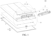
FIG. 1 is an exploded view of a battery pack according to an embodiment of the present disclosure. -
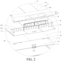
FIG. 2 is an enlarged view of A inFIG. 1 . -
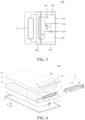
FIG. 3 is a schematic structural diagram (a heating film is connected with a distribution box) of a heating circuit of a heating film of the battery pack according to an embodiment of the present disclosure. -
FIG. 4 is an exploded view of the battery pack according to some other embodiments of the present disclosure. -
FIG. 5 is an enlarged view of B inFIG. 4 . -
FIG. 6 is a schematic diagram of a vehicle according to the present disclosure; -
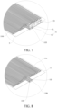
FIG. 7 is a sectional view of a panel fitted with a thermoregulation member according to the present disclosure. -
FIG. 8 is a schematic diagram of the thermoregulation member according to the present disclosure. -
Battery box 1,Box portion 11,Cell mounting cavity 111, Sealingcover 12, Mountingport 121,Distribution cavity 13,Distribution box 2,Panel 21,Distribution module 22,Bottom protection plate 3,Groove area 31,Connection turnup 32,Heating film 4,Positive lead 41,Negative lead 42,Thermoregulation member 5,Adapter 51, Refrigerant inlet/outlet joint 6,Outer inlet 61,Outer outlet 62,Positive avoidance port 71,Negative avoidance port 72, Liquidcooling avoidance port 8, Sealingplate 10, - Battery pack
positive lead 101, Battery packnegative lead 102,First flow channel 103,Second flow channel 104,Adapter inlet 105,Adapter outlet 106,Relay 200,Fuse 300,Cell area 400,Distribution box area 500. - Embodiments of the present disclosure are described in detail below, and examples of the embodiments are shown in the drawings, where the same or similar elements or the elements having the same or similar functions are represented by the same or similar reference numerals throughout the description. The embodiments described below with reference to the drawings are exemplary and used only for explaining the present disclosure, and should not be construed as a limitation on the present disclosure.
- A
battery pack 100 in the embodiments of the present disclosure is described below with reference toFIG. 1 to FIG. 8 . - As shown in
FIG. 1 ,FIG. 4 , andFIG. 7 , thebattery pack 100 in the embodiments of the present disclosure includes abattery box 1 and athermoregulation member 5. - The
battery box 1 may be made of an aluminum alloy material, so as to reduce an entire weight of thebattery pack 100 and achieve a lightweight design of thebattery pack 100. Thebattery box 1 may be constructed as a hollow cavity structure, in which a mounting space is formed to facilitate mounting of a cell inside thebattery box 1, so that thebattery box 1 can support and protect the cell, thereby ensuring stability of the cell. In addition, thebattery box 1 has adistribution cavity 13. Thedistribution cavity 13 is formed on an upper side of thebattery box 1, and adistribution box 2 is arranged in thedistribution cavity 13, which facilitates mounting of thedistribution box 2 in thedistribution cavity 13, thereby reducing difficulty in mounting thedistribution box 2, implementing quick mounting, and facilitates power distribution for the cell inside thebattery box 1. Thedistribution box 2 may include a distribution assembly or adistribution module 21 and apanel 22. Thepanel 22 is fixedly connected with thedistribution module 21, and thepanel 22 is provided with a refrigerant inlet/outlet joint 6 exposed to thebattery box 1. Thepanel 22 is provided with a first flow channel (103) and the refrigerant inlet/outlet joint 6 in communication with the first flow channel (103). As shown inFIG. 2 andFIG. 5 , the refrigerant inlet/outlet joint 6 is arranged on thepanel 22 and is exposed away from thebattery box 1, to facilitate communication of the refrigerant inlet/outlet joint 6 with an external pipeline, thereby reducing difficulty in connecting to the external pipeline, improving assembly efficiency, facilitating disassembly of the external pipeline, and reducing maintenance costs. - The
thermoregulation member 5 is connected with thebattery box 1, and thethermoregulation member 5 has a second flow channel (104) in communication with the first flow channel (103). That is to say, the first flow channel (103) and the second flow channel (104) may be in communication with the external pipeline through the refrigerant inlet/outlet joint 6. It may be understood that thethermoregulation member 5 may be connected to thebattery box 1 through a thermally conductive structural adhesive, to fixedly mount thethermoregulation member 5 to thebattery box 1, thereby ensuring stability of the connection between the thermoregulation member and the battery box. In addition, the first flow channel (103) and the second flow channel (104) may be in communication with the external pipeline through the refrigerant inlet/outlet joint 6, so that a refrigerant may flow in the first flow channel (103) to cool thedistribution box 2. Moreover, the refrigerant may flow to the second flow channel (104) through the first flow channel (103) to cool the cell, which facilitates temperature control of the cell in thebattery box 1. In this way, surroundings of the cell are in an environment with a uniform temperature during heating or cooling, which reduces life degradation of the cell caused by non-uniform temperatures. - In the
battery pack 100 in the embodiments of the present disclosure, through arrangement of the whole flow channel that communicates thethermoregulation member 5 with thepanel 22, not only the cell can be cooled, but also electrical elements in thedistribution box 2 can be cooled, so that thethermoregulation member 5 and thepanel 22 do not need to be provided with additional pipe joints. Therefore, a quantity of pipe joints is reduced, relatively few cooling structures are required, and cooling costs are relatively low. - In some embodiments, the
thermoregulation member 5 is arranged below thebattery box 1. The thermoregulation member is connected to the battery box through the thermally conductive structural adhesive, to fixedly mount thethermoregulation member 5 below thebattery box 1, thereby ensuring the stability of the connection between the thermoregulation member and the battery box. As shown inFIG. 2 , a lead avoidance port and a liquidcooling avoidance port 8 are arranged on a bottom wall of thedistribution cavity 13 spaced apart from each other, to reduce difficulty in forming the lead avoidance port and the liquid cooling avoidance port, and to shield the lead avoidance port and the liquidcooling avoidance port 8 through thedistribution box 2. In this way, water can be prevented from entering the lead avoidance port and the liquidcooling avoidance port 8, and the lead avoidance port and the liquidcooling avoidance port 8 become invisible when viewed from outside of thebattery pack 100, thereby enhancing safety of the battery pack. - An adapter of the second flow channel (104) extends through the liquid
cooling avoidance port 8 and is in communication with the first flow channel (103). That is to say, the liquidcooling avoidance port 8 is configured to give way to anadapter 51 of thethermoregulation member 5, and the adapter is in communication with the first flow channel (103) and the second flow channel (104) simultaneously. In other words, thethermoregulation member 5 is directly connected to the refrigerant inlet/outlet joint 6 through the liquidcooling avoidance port 8, which reduces a distance of connection between the thermoregulation member and the refrigerant inlet/outlet joint, reduces an entire volume of thebattery pack 100, and facilitates formation of a refrigerant circuit between thethermoregulation member 5 and the refrigerant inlet/outlet joint 6. That is to say, the refrigerant may move to thethermoregulation member 5 through thedistribution box 2, so that the cell may be heated or cooled through thethermoregulation member 5, thereby ensuring that the cell is in a relatively uniform temperature condition, improving a service life of the cell, avoiding thermal runaway of the cell caused by a high temperature, and enhancing safety of thebattery pack 100. - As shown in
FIG. 2 andFIG. 8 , the liquidcooling avoidance port 8 may be constructed as an oblong port. In this way, processing difficulty is reduced, and an adapter inlet (105) and an adapter outlet (106) of thethermoregulation member 5 both may extend to thedistribution cavity 13 through the liquidcooling avoidance port 8. It should be noted that, theadapter 51 includes the adapter inlet (105) and the adapter outlet (106). The adapter inlet (105) and the adapter outlet (106) of theadapter 51 both extend into thedistribution cavity 13 through the liquidcooling avoidance port 8, and are connected with a bottom wall of thepanel 22, and are fixed at a joint between thethermoregulation member 5 and thedistribution box 2 through a fixing structure. The fixing structure may be a bolt. In this way, the stability of the connection between thethermoregulation member 5 and thedistribution box 2 is enhanced. - The first flow channel (103) includes a bottom inlet and a bottom outlet arranged on the bottom wall of the
panel 22. The bottom inlet is connected with the adapter inlet (105), and the bottom outlet is connected with the adapter outlet (106). In this way, the refrigerant may enter anouter inlet 61 through the external pipeline, and then successively pass through the bottom inlet, the adapter inlet (105), the adapter outlet (106), the bottom outlet, and anouter outlet 62. Therefore, thedistribution box 2 and the cell can be effectively cooled, so that a high temperature of thedistribution box 2 and the cell can be avoided, and it is ensured that the cell is in a working environment with a normal temperature, thereby enhancing the safety of thebattery pack 100. - In some embodiments, as shown in
FIG. 2 , a mountingport 121 in communication with outside is arranged in thedistribution cavity 13, and thepanel 22 is arranged directly facing the mountingport 121. It may be understood that the mountingport 121 can be constructed as an elongated hole. The mountingport 121 is configured to give way to thepanel 22, which facilitates user operations on thepanel 22, thereby improving convenience of the user operations. - As shown in
FIG. 2 , the refrigerant inlet/outlet joint 6 includes theouter inlet 61 and theouter outlet 62 arranged on thepanel 22. Theouter inlet 61 and theouter outlet 62 are both located on thepanel 22, and theouter inlet 61 and theouter outlet 62 extend through the mountingport 121 to outside of the mountingport 121, so that theouter inlet 61 and theouter outlet 62 can be in communication with the external pipeline, which reduces difficulty in connecting to the external pipeline, improves assembly efficiency, facilitates disassembly of the external pipeline, reduces maintenance costs, and facilitates user operations on thedistribution box 2 through thepanel 22 at the mountingport 121, thereby enhancing safety and practicality of thedistribution box 2. - As shown in
FIG. 1 andFIG. 2 , in some embodiments, thebattery box 1 includes abox portion 11 and a sealingcover 12. - A
heating film 4 is connected with thebox portion 11, which is configured to be turned on at a low temperature to heat thebattery pack 100, so as to achieve thermal uniformity of thebattery pack 100, thereby improving the service life of the cell. In addition, theheating film 4 is mounted to an outer side of thebattery box 1 and is connected through a thermally conductive structural adhesive, so that surroundings of the cell can be in an environment with a uniform temperature during heating or cooling through high thermal conductivity of the aluminum alloy battery box, thereby reducing life degradation of lithium batteries caused by non-uniform temperatures. - The sealing
cover 12 may be constructed as a structure with an opening. The sealingcover 12 is mounted to an end portion of thebox portion 11 and defines thedistribution cavity 13 with thebox portion 11, so as to fixedly mount thedistribution box 2 in thedistribution cavity 13, thereby preventing displacement or detachment of thedistribution box 2, and enhancing stability of thedistribution box 2. Moreover, the opening of the sealingcover 12 is recessed away from an upper surface of thebox portion 11, so as to mount the sealingcover 12 on an upper side of thebox portion 11. Further, the sealingcover 12 and thebox portion 11 jointly define thedistribution cavity 13 for mounting thedistribution box 2. The sealingcover 12 is provided with the mountingport 121. The mountingport 121 is arranged on a side wall of the sealingcover 12. The mountingport 121 may be constructed as an elongated hole. The mountingport 121 is configured to give way to thepanel 22, to facilitate user operations, thereby improving convenience of the user operations. It may be understood that during specific mounting, thedistribution box 2 may be first mounted to an upper surface of thebox portion 11, then the sealingcover 12 is mounted to thedistribution box 2, and thepanel 22 protrudes out through the mountingport 121. In this way, the sealingcover 12 can protect thedistribution box 2, which prevents thedistribution box 2 from direct impact, and facilitates the user operations on thedistribution box 2 through thepanel 22 at the mountingport 121, thereby enhancing the safety and practicality of thedistribution box 2. - It should be noted that, the sealing
cover 12 and the upper surface of thebox portion 11 are sealed by using a bolt and a compressible material through mechanical compression. The level of the sealing is IP67, which enhances the sealing and safety of thebattery pack 100. - In some embodiments, the
battery pack 100 further includes abottom protection plate 3. Thebottom protection plate 3 may be constructed as a plate-shaped structure, so as to facilitate mounting of thebottom protection plate 3 below thebattery box 1, thereby protecting thebattery box 1 through thebottom protection plate 3. In this way, a bottom of thebattery box 1 can be prevented from direct impact, thereby enhancing the safety of thebattery pack 100. - The
bottom protection plate 3 is mounted to the bottom of thebattery box 1, and thethermoregulation member 5 is located between thebattery box 1 and thebottom protection plate 3, so that thebottom protection plate 3 can support and protect thethermoregulation member 5, thereby preventing detachment or displacement of thethermoregulation member 5, and enhancing stability of thethermoregulation member 5. In addition, thethermoregulation member 5 is arranged between a bottom wall of thebattery box 1 and thebottom protection plate 3, so that the surroundings of the cell can be in an environment with a uniform temperature during heating or cooling through control of thethermoregulation member 5, thereby reducing life degradation of lithium batteries caused by non-uniform temperatures. - It should be noted that, the
bottom protection plate 3 and a lower surface of thebattery box 1 are sealed by using a bolt and a compressible material. In this way, thethermoregulation member 5 can be reliably sealed between thebattery box 1 and thebottom protection plate 3, and thus can be in a stable working environment, thereby improving the sealing and safety of thebattery pack 100. - In some embodiments, the
battery pack 100 further includes aheating film 4. Theheating film 4 is mounted above or below thebattery box 1, and theheating film 4 is electrically connected with thedistribution box 2. For example, theheating film 4 is mounted above thebattery box 1, or theheating film 4 is mounted below thebattery box 1. In other words, a mounting position of theheating film 4 may be designed according different mounting requirements. Theheating film 4 is arranged on the outer side of thebattery box 1, which is configured to be turned on at a low temperature to heat thebattery pack 100, so as to achieve thermal uniformity of thebattery pack 100, thereby improving the service life of the cell. In addition, theheating film 4 is mounted to the outer side of thebattery box 1 and is connected through a thermally conductive structural adhesive, so that the surroundings of the cell can be in an environment with a uniform temperature during heating or cooling through the high thermal conductivity of the aluminum alloy battery box, thereby reducing life degradation of lithium batteries caused by non-uniform temperatures. - As shown in
FIG. 1 andFIG. 2 , theheating film 4 is arranged between thebattery box 1 and thethermoregulation member 5. The bottom wall of thedistribution cavity 13 is provided with the lead avoidance port. The lead avoidance port and the liquidcooling avoidance port 8 are spaced apart from each other, to reduce the difficulty in forming the lead avoidance port and the liquid cooling avoidance port, and to shield the lead avoidance port and the liquidcooling avoidance port 8 through thedistribution box 2. In this way, water can be prevented from entering the lead avoidance port and the liquidcooling avoidance port 8, and the lead avoidance port and the liquidcooling avoidance port 8 become invisible when viewed from the outside of thebattery pack 100, thereby enhancing the safety of the battery pack. - An electrode lead of the
heating film 4 extends through the lead avoidance port and is electrically connected with thedistribution box 2. It may be understood that, theheating film 4 is mounted below thebattery box 1, thethermoregulation member 5 is also mounted below thebattery box 1, theheating film 4 is electrically connected with thedistribution box 2, and the bottom wall of thedistribution cavity 13 is provided with the lead avoidance port. It may be understood that, in some embodiments, as shown inFIG. 1 , theheating film 4 and thethermoregulation member 5 are mounted below thebattery box 1. That is to say, theheating film 4 and thethermoregulation member 5 are snugly attached to a low part of thebattery box 1 in sequence and are connected through the thermally conductive structural adhesive. In this way, the high heat conductivity can be achieved through the aluminumalloy battery box 1. - The lead avoidance port includes a
positive avoidance port 71 and anegative avoidance port 72. Thepositive avoidance port 71 and thenegative avoidance port 72 both may be constructed as square holes, so as to reduce difficulty in forming the positive avoidance port and the negative avoidance port, and to facilitate mounting and connection of another structure. As shown inFIG. 2 , thepositive avoidance port 71 and thenegative avoidance port 72 are respectively located in two end areas of the bottom wall of thebattery box 1. In other words, thepositive avoidance port 71 and thenegative avoidance port 72 are spaced apart on the bottom wall of thebattery box 1. - Specifically, the electrode lead of the
heating film 4 includes apositive lead 41 and anegative lead 42. Thepositive lead 41 of theheating film 4 extends through thepositive avoidance port 71 and is electrically connected with thedistribution box 2. Thenegative lead 42 of theheating film 4 extends through thenegative avoidance port 72 and is electrically connected with thedistribution box 2. That is to say, the electrode lead of theheating film 4 directly passes through the lead avoidance port and is electrically connected with thedistribution box 2, which reduces a distance of connection between the electrode lead and the distribution box, reduces an entire volume of thebattery pack 100, and facilitates formation of a heating circuit between theheating film 4 and thedistribution box 2, that is, thedistribution box 2 can supply power to theheating film 4. In this way, during heating of the cell, power is supplied to theheating film 4 through thedistribution box 2, so that theheating film 4 is heated up, and then the heat is transmitted to the cell through thebattery box 1, to heat up the cell. Through such an arrangement, electricity can be obtained inside theheating film 4, which eliminates a need to arrange an additional power supply for theheating film 4, thereby reducing costs. - As shown in
FIG. 4 andFIG. 5 , theheating film 4 is mounted above thebattery box 1, a top wall of thebattery box 1 is provided with the lead avoidance port, and the electrode lead of theheating film 4 extends through the lead avoidance port and is electrically connected with thedistribution box 2. That is to say, theheating film 4 is tightly attached to an upper part of thebattery box 1 and is connected through the thermally conductive structural adhesive, thereby achieving the high thermal conductivity through the aluminumalloy battery box 1. - In some embodiments, the lead avoidance port includes a
positive avoidance port 71 and anegative avoidance port 72. As shown inFIG. 5 , thepositive avoidance port 71 and thenegative avoidance port 72 are respectively located in two side areas of the top wall of thebattery box 1, so as to reduce difficulty in forming the positive avoidance port and the negative avoidance port, and to facilitate mounting and connection of another structure. Thepositive lead 41 of theheating film 4 extends through thepositive avoidance port 71 and is electrically connected with thedistribution box 2. Thenegative lead 42 of theheating film 4 extends through thenegative avoidance port 72 and is electrically connected with thedistribution box 2. That is to say, the electrode lead of theheating film 4 directly passes through the lead avoidance port and is electrically connected with thedistribution box 2, which reduces a distance of connection between the electrode lead and the distribution box, reduces an entire volume of thebattery pack 100, and facilitates formation of a heating circuit between theheating film 4 and thedistribution box 2, that is, thedistribution box 2 can supply power to theheating film 4. In this way, during heating of the cell, power is supplied to theheating film 4 through thedistribution box 2, so that theheating film 4 is heated up, and then the heat is transmitted to the cell through thebattery box 1, to heat up the cell. - In some embodiments, the
battery pack 100 further includes a sealingplate 10. The sealingplate 10 is mounted above thebattery box 1, and theheating film 4 is located between the sealingplate 10 and thebattery box 1. It may be understood that, as shown inFIG. 4 andFIG. 5 , theheating film 4 is arranged between the sealingplate 10 and thebattery box 1. The sealingplate 10 may be constructed as a plate-shaped structure, to facilitate mounting of the sealingplate 10 above thebattery box 1, thereby sealing thepositive avoidance port 71 and thenegative avoidance port 72 through the sealingplate 10, and protecting theheating film 4. - Further, the
heating film 4 is located between the sealingplate 10 and thebattery box 1. In other words, theheating film 4 is arranged between the sealingplate 10 and thebattery box 1. The sealingplate 10 protects theheating film 4, and is configured to be turned on at a low temperature to heat thebattery pack 100. In this way, thermal uniformity of thebattery pack 100 is realized, and the service life of the cell is increased. - It should be noted that, as shown in
FIG. 3 , theheating film 4 is electrically connected with thedistribution box 2, which forms a heating circuit for thebattery pack 100. Thepositive lead 41 and thenegative lead 42 of theheating film 4 respectively pass through acell area 400 and adistribution box area 500 and are connected with a battery packpositive lead 101 and a battery packnegative lead 102. In addition, arelay 200 and afuse 300 are further connected to a line of thepositive lead 41 of theheating film 4, to adjust and control the heating circuit, so as to enhance safety of the heating circuit. Moreover, when theheating film 4 is electrically connected with thedistribution box 2, the heating film may be turn on in a case that thebattery pack 100 is at a low temperature, to heat the cell. In this way, the thermal uniformity of thebattery pack 100 is realized, which increases the service life of the cell, and enhances the practicality and safety of thebattery pack 100. - In some embodiments, as shown in
FIG. 4 , thebottom protection plate 3 includes agroove area 31 recessed downward and aconnection turnup 32 surrounding thegroove area 31. Thethermoregulation member 5 is mounted in thegroove area 31. Thegroove area 31 and theconnection turnup 32 may be integrally formed to reduce processing difficulty. - Specifically, the
groove area 31 is recessed in away from thebattery box 1, to form an avoidance space. Thethermoregulation member 5 is located in thegroove area 31, that is, during specific mounting, thethermoregulation member 5 is mounted between thebattery box 1 and thebottom protection plate 3, and thethermoregulation member 5 is located between thegroove area 31 and thebattery box 1. Therefore, since thegroove area 31 gives way to thethermoregulation member 5, quick mounting of thethermoregulation member 5 is realized, and since thegroove area 31 limits thethermoregulation member 5, random movement of the thermoregulation member is prevented. - The
connection turnup 32 is configured to be detachably connected with thebattery box 1, which facilitates detachable mounting of thebottom protection plate 3 to a lower side of thebattery box 1, reduces mounting difficulty, and facilitates detachment of thebottom protection plate 3, thereby reducing maintenance costs of thebattery pack 100, and enhancing the practicality of thebattery pack 100. - In some embodiments, as shown in
FIG. 2 , thebattery box 1 further includes acell mounting cavity 111. - The
cell mounting cavity 111 is formed in an internal space of thebox portion 11. Thecell mounting cavity 111 is configured for the cell to be mounted, and the cell is electrically connected with thedistribution box 2. Multiplecell mounting cavities 111 may be arranged, so that multiple cells may be separately mounted in thecell mounting cavities 111, thereby facilitating assembly of the cells, and realizing support and protection of the cells through thecell mounting cavities 111. - As shown in
FIG. 1 , thedistribution cavity 13 is located at an end portion of thecell mounting cavity 111, and the cell is electrically connected with thedistribution box 2, to reduce a distance of connection between the cell and thedistribution box 2, thereby improving a volume integration of thebattery pack 100, reducing the entire volume of thebattery pack 100, and facilitating the electrical connection between the cell and thedistribution box 2, and thus enhancing the practicality of thebattery pack 100. - As shown in
FIG. 1 andFIG. 2 , in some embodiments, thebattery box 1 includes thebox portion 11 and the sealingcover 12. - The
heating film 4 is connected with thebox portion 11, which is configured to be turned on at a low temperature to heat thebattery pack 100, so as to achieve thermal uniformity of thebattery pack 100, thereby improving the service life of the cell. In addition, theheating film 4 is mounted to the outer side of thebattery box 1 and is connected through the thermally conductive structural adhesive, so that surroundings of the cell can be in an environment with a uniform temperature during heating or cooling through high thermal conductivity of the aluminum alloy battery box, thereby reducing life degradation of lithium batteries caused by non-uniform temperatures. - The sealing
cover 12 may be constructed as a structure with an opening. The sealingcover 12 is mounted to an end portion of thebox portion 11 and defines thedistribution cavity 13 with thebox portion 11, so as to fixedly mount thedistribution box 2 in thedistribution cavity 13, thereby preventing displacement or detachment of thedistribution box 2, and enhancing stability of thedistribution box 2. Moreover, the opening of the sealingcover 12 is recessed away from an upper surface of thebox portion 11, so as to mount the sealingcover 12 on an upper side of thebox portion 11. Further, the sealingcover 12 and thebox portion 11 jointly define thedistribution cavity 13 for mounting thedistribution box 2. The sealingcover 12 is provided with the mountingport 121. The mountingport 121 is arranged on a side wall of the sealingcover 12. The mountingport 121 may be constructed as an elongated hole. The mountingport 121 is configured to give way to thepanel 22, to facilitate user operations, thereby improving convenience of the user operations. It may be understood that during specific mounting, thedistribution box 2 may be first mounted to an upper surface of thebox portion 11, then the sealingcover 12 is mounted to thedistribution box 2, and thepanel 22 protrudes out through the mountingport 121. In this way, the sealingcover 12 can protect thedistribution box 2, which prevents thedistribution box 2 from direct impact, and facilitates the user operations on thedistribution box 2 through thepanel 22 at the mountingport 121, thereby enhancing the safety and practicality of thedistribution box 2. - It should be noted that, the sealing
cover 12 and the upper surface of thebox portion 11 are sealed by using the bolt and the compressible material through mechanical compression. A level of the sealing is IP67, which enhances the sealing and safety of thebattery pack 100. - A vehicle in the embodiments of the present disclosure is briefly described below.
- As shown in
FIG. 6 , avehicle 200 in the embodiments of the present disclosure includes theabove battery pack 100. Since thevehicle 200 in the embodiments of the present disclosure is provided with theabove battery pack 100, a battery storage unit of thevehicle 200 has a simple structure and requires low costs, thereby reducing manufacturing costs of the whole vehicle. - In the descriptions of the present disclosure, it should be understood that orientation or position relationships indicated by the terms such as "center", "longitudinal", "transverse", "length", "width", "thickness", "up", "down", "front", "back", "left", "right", "vertical", "horizontal", "top", "bottom", "inside", "outside", "clockwise", "anticlockwise", "axial direction", "radial direction", and "circumferential direction" are based on orientation or position relationships shown in the drawings, and are merely used for ease and brevity of description of the present disclosure, rather than indicating or implying that the mentioned device or element needs to have a particular orientation or be constructed and operated in a particular orientation. Therefore, such terms should not be construed as a limitation on the present disclosure.
- In addition, the terms "first" and "second" are merely used for the purpose of description, and shall not be construed as indicating or implying relative importance or implying a quantity of indicated technical features. Therefore, features defined by "first" and "second" may explicitly or implicitly include one or more such features. In the descriptions of the present disclosure, "multiple" means more than two, unless otherwise definitely and specifically defined.
- In the present disclosure, unless otherwise explicitly specified or defined, the terms such as "mount", "connect", "connection", and "fix" should be understood in a broad sense. For example, the connection may be a fixed connection, a detachable connection, or an integral connection; or the connection may be a mechanical connection or an electrical connection; or the connection may be a direct connection, an indirect connection through an intermediate medium, internal communication between two elements, or an interaction relationship between two elements. A person of ordinary skill in the art may understand the specific meanings of the above terms in the present disclosure according to specific situations.
- In the present disclosure, unless otherwise explicitly specified and defined, a first feature being "on" or "under" a second feature may indicate that the first feature is in direct contact with the second feature, or the first feature is in indirect contact with the second feature by using an intermediate medium. In addition, the first feature being "above", "over", or "on" the second feature may indicate that the first feature is directly above or obliquely above the second feature, or may merely indicate that the first feature is at a higher horizontal position than the second feature. The first feature being "below", "under", and "beneath" the second feature may indicate that the first feature is directly below or obliquely below the second feature, or merely indicates that the first feature is at a lower horizontal position than the second feature.
- In the descriptions of the specification, a description with reference to terms such as "an embodiment", "some embodiments", "an example", "a specific example", or "some examples" means that specific features, structures, materials, or characteristics described with reference to the embodiment or the example is included in at least one embodiment or example of the present disclosure. In this specification, exemplary descriptions of the above terms are not necessarily directed at the same embodiment or example. Besides, the specific features, the structures, the materials, or the characteristics that are described may be combined in proper manners in any one or more embodiments or examples. In addition, a person skilled in the art may integrate or combine different embodiments or examples described in the specification and features of the different embodiments or examples as long as they are not contradictory to each other.
- Although the embodiments of the present disclosure have been shown and described above, it may be understood that, the above embodiments are exemplary and should not be understood as a limitation on the present disclosure. A person of ordinary skill in the art may make changes, modifications, replacements, or variations to the above embodiments within the scope of the present disclosure.
Claims (14)
- A battery pack (100), comprising:a battery box (1), the battery box (1) having a distribution cavity; a distribution box (2) being arranged in the distribution cavity; the distribution box (2) comprising a panel (21); and the panel (21) having a first flow channel (103) and a refrigerant inlet/outlet joint (6) in communication with the first flow channel (103); anda thermoregulation member (5), the thermoregulation member (5) being connected with the battery box (1); and the thermoregulation member (5) having a second flow channel (104) in communication with the first flow channel (103).
- The battery pack (100) according to claim 1, wherein the thermoregulation member (5) is arranged below the battery box (1); a liquid cooling avoidance port (8) is arranged on a bottom wall of the distribution cavity; and an adapter (51) of the second flow channel (104) extends through the liquid cooling avoidance port (8) and is in communication with the first flow channel (103).
- The battery pack (100) according to claim 2, wherein the liquid cooling avoidance port (8) is constructed as an oblong port; the adapter (51) comprises an adapter inlet (105) and an adapter outlet (106); and the adapter inlet (105) and the adapter outlet (106) both extend into the distribution cavity through the liquid cooling avoidance port (8).
- The battery pack (100) according to claim 3, wherein the refrigerant inlet/outlet joint (6) comprises an outer inlet (61) and an outer outlet (62) arranged on an outer side surface of the panel (21),
wherein the outer inlet (61) is in communication with the adapter inlet (105); the outer outlet (62) is in communication with the adapter outlet (106); and the outer inlet (61) and the outer outlet (62) are configured to be in communication with an external pipeline. - The battery pack (100) according to claim 4, wherein a mounting port (121) in communication with outside is arranged in the distribution cavity; the panel (21) is arranged directly facing the mounting port (121); and the outer inlet (61) and the outer outlet (62) extend out through the mounting port (121).
- The battery pack (100) according to claim 5, wherein the battery box (1) comprises a box portion (11) and a sealing cover (12); the thermoregulation member (5) is connected with the box portion (11); the sealing cover (12) is mounted to an end portion of the box portion (11) to define the distribution cavity with the box portion (11); and the sealing cover (12) is provided with the mounting port (121).
- The battery pack (100) according to any of claims 2 to 6, further comprising a bottom protection plate (3), the bottom protection plate (3) being arranged to cover a bottom of the battery box (1); and the thermoregulation member (5) being located between the battery box (1) and the bottom protection plate (3).
- The battery pack (100) according to any of claims 2 to 7, further comprising a heating film (4), the heating film (4) being mounted above or below the battery box (1); and the heating film (4) being electrically connected with the distribution box (2).
- The battery pack (100) according to claim 8, wherein the heating film (4) is arranged between the battery box (1) and the thermoregulation member (5); a lead avoidance port is arranged on the bottom wall of the distribution cavity; the lead avoidance port is spaced apart from the liquid cooling avoidance port (8); and an electrode lead of the heating film (4) extends through the lead avoidance port and is electrically connected with the distribution box (2).
- The battery pack (100) according to claim 8 or 9, wherein the heating film (4) is arranged above the battery box (1); a top wall of the battery box (1) is provided with the lead avoidance port; and the electrode lead of the heating film (4) extends through the lead avoidance port and is electrically connected with the distribution box (2).
- The battery pack (100) according to claim 10, further comprising a sealing plate (10), the sealing plate (10) being mounted above the battery box (1); and the heating film (4) being located between the sealing plate (10) and the battery box (1).
- The battery pack (100) according to claim 7, wherein the bottom protection plate (3) comprises a groove area (31) recessed downward and a connection turnup (32) surrounding the groove area (31); the connection turnup (32) is configured to be detachably connected with the battery box (1); and the thermoregulation member (5) is mounted in the groove area (31).
- The battery pack (100) according to any of claims 1 to 12, further comprising a cell mounting cavity (111), the cell mounting cavity (111) being configured for a cell to be mounted; the distribution cavity being located at an end portion of the cell mounting cavity (111); and the cell being electrically connected with the distribution box (2).
- A vehicle (200), comprising the battery pack (100) according to any of claims 1 to 13.
Applications Claiming Priority (2)
| Application Number | Priority Date | Filing Date | Title |
|---|---|---|---|
| CN202110739653.1A CN115621635B (en) | 2021-06-30 | 2021-06-30 | Battery Pack |
| PCT/CN2022/100482 WO2023273989A1 (en) | 2021-06-30 | 2022-06-22 | Battery pack |
Publications (3)
| Publication Number | Publication Date |
|---|---|
| EP4300660A1 true EP4300660A1 (en) | 2024-01-03 |
| EP4300660A4 EP4300660A4 (en) | 2024-10-02 |
| EP4300660B1 EP4300660B1 (en) | 2026-04-01 |
Family
ID=84691354
Family Applications (1)
| Application Number | Title | Priority Date | Filing Date |
|---|---|---|---|
| EP22831805.1A Active EP4300660B1 (en) | 2021-06-30 | 2022-06-22 | Battery pack |
Country Status (7)
| Country | Link |
|---|---|
| US (1) | US20240021912A1 (en) |
| EP (1) | EP4300660B1 (en) |
| JP (1) | JP2024515013A (en) |
| KR (1) | KR20230148835A (en) |
| CN (1) | CN115621635B (en) |
| CA (1) | CA3213980A1 (en) |
| WO (1) | WO2023273989A1 (en) |
Families Citing this family (4)
| Publication number | Priority date | Publication date | Assignee | Title |
|---|---|---|---|---|
| CN217655952U (en) * | 2022-04-07 | 2022-10-25 | 中创新航科技股份有限公司 | Liquid cooling system, battery box and battery package |
| CN119447558A (en) * | 2023-07-31 | 2025-02-14 | 宁德时代新能源科技股份有限公司 | Energy storage box and energy storage system |
| CN221466749U (en) * | 2023-11-09 | 2024-08-02 | 比亚迪股份有限公司 | Switching structure, battery pack and electric equipment |
| JP2025163516A (en) * | 2024-04-17 | 2025-10-29 | トヨタ自動車株式会社 | Vehicle, power storage device and temperature control device |
Family Cites Families (16)
| Publication number | Priority date | Publication date | Assignee | Title |
|---|---|---|---|---|
| JP2000348781A (en) * | 1999-06-04 | 2000-12-15 | Japan Storage Battery Co Ltd | Non-aqueous electrolyte battery |
| JP5091758B2 (en) * | 2008-05-07 | 2012-12-05 | 本田技研工業株式会社 | Electrical box |
| JP5239759B2 (en) * | 2008-11-12 | 2013-07-17 | 株式会社デンソー | Battery cooling device |
| JP2013012441A (en) * | 2011-06-30 | 2013-01-17 | Sanyo Electric Co Ltd | Electric power source device and vehicle including the same |
| CN106816671B (en) * | 2015-12-01 | 2019-02-22 | 宁德时代新能源科技股份有限公司 | battery unit, battery module and battery pack |
| JP6693338B2 (en) * | 2016-08-26 | 2020-05-13 | 株式会社デンソー | Battery pack |
| HUE063836T2 (en) * | 2018-06-06 | 2024-02-28 | Samsung Sdi Co Ltd | Detecting abnormal battery system conditions |
| JP7058197B2 (en) * | 2018-08-20 | 2022-04-21 | 本田技研工業株式会社 | Vehicle battery device |
| CN109148771B (en) * | 2018-08-23 | 2021-07-23 | 北京新能源汽车股份有限公司 | Battery pack |
| US11189867B2 (en) * | 2018-11-16 | 2021-11-30 | Chongqing Jinkang Powertrain New Energy Co., Ltd. | Battery packs with integrated cold plates for electric vehicles |
| CN210805903U (en) * | 2019-09-30 | 2020-06-19 | 比亚迪股份有限公司 | Battery pack |
| DE102019216968A1 (en) * | 2019-11-04 | 2021-05-06 | Robert Bosch Gmbh | Battery housing for a battery module and battery module with a battery housing |
| CN212587601U (en) * | 2020-05-22 | 2021-02-23 | 比亚迪股份有限公司 | A kind of battery pack and electric vehicle |
| CN212485392U (en) * | 2020-06-30 | 2021-02-05 | 中国第一汽车股份有限公司 | Soft packet of power battery assembly of pure electric vehicles and pure electric vehicles |
| CN113054299B (en) * | 2021-03-12 | 2022-05-31 | 安徽舟之航电池有限公司 | Liquid cooling integrated power battery system for new energy automobile |
| CN215119037U (en) * | 2021-06-30 | 2021-12-10 | 比亚迪股份有限公司 | Battery pack |
-
2021
- 2021-06-30 CN CN202110739653.1A patent/CN115621635B/en active Active
-
2022
- 2022-06-22 KR KR1020237032260A patent/KR20230148835A/en not_active Ceased
- 2022-06-22 JP JP2023555711A patent/JP2024515013A/en not_active Ceased
- 2022-06-22 EP EP22831805.1A patent/EP4300660B1/en active Active
- 2022-06-22 CA CA3213980A patent/CA3213980A1/en active Pending
- 2022-06-22 WO PCT/CN2022/100482 patent/WO2023273989A1/en not_active Ceased
-
2023
- 2023-09-27 US US18/373,794 patent/US20240021912A1/en active Pending
Also Published As
| Publication number | Publication date |
|---|---|
| US20240021912A1 (en) | 2024-01-18 |
| CN115621635A (en) | 2023-01-17 |
| CA3213980A1 (en) | 2023-01-05 |
| JP2024515013A (en) | 2024-04-04 |
| CN115621635B (en) | 2024-10-11 |
| EP4300660B1 (en) | 2026-04-01 |
| KR20230148835A (en) | 2023-10-25 |
| EP4300660A4 (en) | 2024-10-02 |
| WO2023273989A1 (en) | 2023-01-05 |
Similar Documents
| Publication | Publication Date | Title |
|---|---|---|
| EP4300660B1 (en) | Battery pack | |
| CN217788535U (en) | A battery pack with a liquid cooling plate | |
| JP7666850B2 (en) | Battery module containing insulating oil and battery pack containing the same | |
| CN214043779U (en) | Immersion type liquid cooling battery module with integrated liquid cooling plate and graphite flake | |
| WO2022135169A1 (en) | Battery module, battery pack and vehicle | |
| CN113224415A (en) | Liquid cooling board and battery package | |
| CN117996262A (en) | Battery module components, battery packs and vehicles | |
| WO2019174408A1 (en) | Battery cover plate assembly, cell, battery pack, power battery, and power vehicle | |
| CN221201312U (en) | Battery, battery module and electrical equipment | |
| CN218568988U (en) | Battery module and electric device | |
| CN215119037U (en) | Battery pack | |
| CN219106291U (en) | Battery module and battery | |
| CN216085090U (en) | Battery package and battery cooling system | |
| CN214411312U (en) | Heat dissipation module and energy storage module | |
| CN115966805A (en) | Air-cooled IP67 rapid heating and heat dissipation battery system | |
| CN210403794U (en) | Power battery pack and vehicle with the same | |
| CN113161662A (en) | Battery package and battery cooling system | |
| CN218123554U (en) | Battery pack with heat dissipation structure | |
| CN223911697U (en) | Battery devices and battery cabinets | |
| CN222927587U (en) | BDU structure and battery pack | |
| US20240106034A1 (en) | Battery pack charging system and charging apparatus | |
| CN216354446U (en) | Battery module | |
| CN221226363U (en) | Integrated battery thermal management system and battery system | |
| CN222619882U (en) | Heat dissipation plate and lithium battery heat dissipation bag | |
| CN220914485U (en) | A battery module and a battery system |
Legal Events
| Date | Code | Title | Description |
|---|---|---|---|
| STAA | Information on the status of an ep patent application or granted ep patent |
Free format text: STATUS: THE INTERNATIONAL PUBLICATION HAS BEEN MADE |
|
| PUAI | Public reference made under article 153(3) epc to a published international application that has entered the european phase |
Free format text: ORIGINAL CODE: 0009012 |
|
| STAA | Information on the status of an ep patent application or granted ep patent |
Free format text: STATUS: REQUEST FOR EXAMINATION WAS MADE |
|
| 17P | Request for examination filed |
Effective date: 20230926 |
|
| AK | Designated contracting states |
Kind code of ref document: A1 Designated state(s): AL AT BE BG CH CY CZ DE DK EE ES FI FR GB GR HR HU IE IS IT LI LT LU LV MC MK MT NL NO PL PT RO RS SE SI SK SM TR |
|
| A4 | Supplementary search report drawn up and despatched |
Effective date: 20240902 |
|
| RIC1 | Information provided on ipc code assigned before grant |
Ipc: H01M 50/204 20210101ALI20240827BHEP Ipc: H01M 10/6571 20140101ALI20240827BHEP Ipc: H01M 10/615 20140101AFI20240827BHEP |
|
| DAV | Request for validation of the european patent (deleted) | ||
| DAX | Request for extension of the european patent (deleted) | ||
| GRAP | Despatch of communication of intention to grant a patent |
Free format text: ORIGINAL CODE: EPIDOSNIGR1 |
|
| STAA | Information on the status of an ep patent application or granted ep patent |
Free format text: STATUS: GRANT OF PATENT IS INTENDED |
|
| INTG | Intention to grant announced |
Effective date: 20251120 |
|
| GRAS | Grant fee paid |
Free format text: ORIGINAL CODE: EPIDOSNIGR3 |
|
| GRAA | (expected) grant |
Free format text: ORIGINAL CODE: 0009210 |
|
| STAA | Information on the status of an ep patent application or granted ep patent |
Free format text: STATUS: THE PATENT HAS BEEN GRANTED |
|
| P01 | Opt-out of the competence of the unified patent court (upc) registered |
Free format text: CASE NUMBER: UPC_APP_0003374_4300660/2026 Effective date: 20260130 |
|
| AK | Designated contracting states |
Kind code of ref document: B1 Designated state(s): AL AT BE BG CH CY CZ DE DK EE ES FI FR GB GR HR HU IE IS IT LI LT LU LV MC MK MT NL NO PL PT RO RS SE SI SK SM TR |
|
| REG | Reference to a national code |
Ref country code: CH Ref legal event code: F10 Free format text: ST27 STATUS EVENT CODE: U-0-0-F10-F00 (AS PROVIDED BY THE NATIONAL OFFICE) Effective date: 20260401 Ref country code: GB Ref legal event code: FG4D |
|
| REG | Reference to a national code |
Ref country code: DE Ref legal event code: R096 Ref document number: 602022033671 Country of ref document: DE |
|
| REG | Reference to a national code |
Ref country code: IE Ref legal event code: FG4D |