EP4300530A1 - Medium voltage or high voltage circuit breaker - Google Patents
Medium voltage or high voltage circuit breaker Download PDFInfo
- Publication number
- EP4300530A1 EP4300530A1 EP22182524.3A EP22182524A EP4300530A1 EP 4300530 A1 EP4300530 A1 EP 4300530A1 EP 22182524 A EP22182524 A EP 22182524A EP 4300530 A1 EP4300530 A1 EP 4300530A1
- Authority
- EP
- European Patent Office
- Prior art keywords
- lever arm
- arm
- linear
- linear lever
- vacuum interrupter
- Prior art date
- Legal status (The legal status is an assumption and is not a legal conclusion. Google has not performed a legal analysis and makes no representation as to the accuracy of the status listed.)
- Granted
Links
Images




Classifications
-
- H—ELECTRICITY
- H01—ELECTRIC ELEMENTS
- H01H—ELECTRIC SWITCHES; RELAYS; SELECTORS; EMERGENCY PROTECTIVE DEVICES
- H01H33/00—High-tension or heavy-current switches with arc-extinguishing or arc-preventing means
- H01H33/60—Switches wherein the means for extinguishing or preventing the arc do not include separate means for obtaining or increasing flow of arc-extinguishing fluid
- H01H33/66—Vacuum switches
- H01H33/666—Operating arrangements
-
- H—ELECTRICITY
- H01—ELECTRIC ELEMENTS
- H01H—ELECTRIC SWITCHES; RELAYS; SELECTORS; EMERGENCY PROTECTIVE DEVICES
- H01H33/00—High-tension or heavy-current switches with arc-extinguishing or arc-preventing means
- H01H33/60—Switches wherein the means for extinguishing or preventing the arc do not include separate means for obtaining or increasing flow of arc-extinguishing fluid
- H01H33/66—Vacuum switches
- H01H33/6606—Terminal arrangements
-
- H—ELECTRICITY
- H01—ELECTRIC ELEMENTS
- H01H—ELECTRIC SWITCHES; RELAYS; SELECTORS; EMERGENCY PROTECTIVE DEVICES
- H01H33/00—High-tension or heavy-current switches with arc-extinguishing or arc-preventing means
- H01H33/60—Switches wherein the means for extinguishing or preventing the arc do not include separate means for obtaining or increasing flow of arc-extinguishing fluid
- H01H33/66—Vacuum switches
- H01H33/664—Contacts; Arc-extinguishing means, e.g. arcing rings
-
- H—ELECTRICITY
- H01—ELECTRIC ELEMENTS
- H01H—ELECTRIC SWITCHES; RELAYS; SELECTORS; EMERGENCY PROTECTIVE DEVICES
- H01H33/00—High-tension or heavy-current switches with arc-extinguishing or arc-preventing means
- H01H33/60—Switches wherein the means for extinguishing or preventing the arc do not include separate means for obtaining or increasing flow of arc-extinguishing fluid
- H01H33/66—Vacuum switches
- H01H33/666—Operating arrangements
- H01H2033/6665—Details concerning the mounting or supporting of the individual vacuum bottles
-
- H—ELECTRICITY
- H01—ELECTRIC ELEMENTS
- H01H—ELECTRIC SWITCHES; RELAYS; SELECTORS; EMERGENCY PROTECTIVE DEVICES
- H01H33/00—High-tension or heavy-current switches with arc-extinguishing or arc-preventing means
- H01H33/60—Switches wherein the means for extinguishing or preventing the arc do not include separate means for obtaining or increasing flow of arc-extinguishing fluid
- H01H33/66—Vacuum switches
- H01H33/666—Operating arrangements
- H01H2033/6667—Details concerning lever type driving rod arrangements
Definitions
- the present invention relates to a medium voltage or high voltage circuit breaker, a drive for a medium voltage or high voltage circuit breaker, and a medium voltage or high voltage switchgear.
- Vacuum interrupters are widely known in the industry, in the applications of low-; medium-; high- voltage circuit breakers.
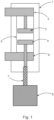
- Fig. 1 shows a standard design of a circuit breaker pole.
- the standard design of the circuit breaker pole has a housing 1, which provides for the proper positioning of internal parts, the upper terminal 2 and the lower terminal 6 provide an interface to the outer environment.
- the circuit breaker also has a vacuum interrupter (VI) 5 and a pushrod 7 transfers the movement of the actuator 8 into the VI.
- the VI 5 has one contact fixed contact 3 and one movable contact 4.
- the fixed contact 3 is both mechanically and electrically connected to the upper terminal 2.
- the moveable contact 4 is in electrical contact with lower contact 6. Mechanical fixation of the moveable contact 4 needs to allow for linear movement of this contact towards the fixed contact 3.
- the housing 1 is also used for improving the dielectric withstand of the whole interior assembly with respect to the surrounding electrical potentials. It is usually made of thermoplastic, duroplastic and/or thermoset material, which enables decreasing distances to the next phase(s) or grounded switchgear walls and provides for increasing creepage distances.
- a medium voltage or high voltage circuit breaker comprising:
- the second vacuum interrupter is connected in series with the first vacuum interrupter, and in a closed state current can flow from the first terminal to the second terminal when movable contacts of both vacuum interrupters are brought into contact with fixed contacts of both vacuum interrupters.
- a compact design is provided, because the movement required by the operating rod is minimised.
- the first non-linear lever arm comprises a first arm part connected to a second arm part.
- the first arm part of the first non-linear lever arm is angled to the second arm part of the first non-linear lever arm.
- An end of the first arm part is the first end of the first non-linear lever arm coupled to the pushrod of the movable contact of the first vacuum interrupter at the first lever arm first end pivot point.
- An end of the second arm part is the second end of the first lever arm coupled to the operating rod at the centre pivot point.
- the second non-linear lever arm comprises a first arm part connected to a second arm part.
- the first arm part of the second non-linear lever arm is angled to the second arm part of the second non-linear lever arm.
- An end of the first arm part is the first end of the second non-linear lever arm coupled to the pushrod of the movable contact of the second vacuum interrupter at the second lever arm first end pivot point.
- An end of the second arm part is the second end of the second lever arm coupled to the operating rod at the centre pivot point.
- a length of the first arm part of the first non-linear lever arm between the first end pivot point and the connection with the second arm part of the first non-linear lever arm is less than a length of the second arm part of the first non-linear lever arm between the centre pivot point and the connection with the first arm part of the first non-linear lever arm.
- a length of the first arm part of the second non-linear lever arm between the first end pivot point and the connection with the second arm part of the second non-linear lever arm is less than a length of the second arm part of the second non-linear lever arm between the centre pivot point and the connection with the first arm part of the second non-linear lever arm.
- the first arm part of the first non-linear lever arm is angled to the second arm part of the first non-linear lever arm at an obtuse angle.
- the first arm part of the second non-linear lever arm is angled to the second arm part of the second non-linear lever arm at an obtuse angle.
- the first arm part of the first non-linear lever arm is angled to the second arm part of the first non-linear lever arm at an angle substantially equal to 90 degrees.
- the first arm part of the second non-linear lever arm is angled to the second arm part of the second non-linear lever arm at an angle substantially equal to 90 degrees.
- the second non-linear lever arm is a mirror image of the first non-linear lever arm.
- the second non-linear lever arm is not a mirror image of the first non-linear lever arm.
- the first vacuum interrupter is of a different design to the second vacuum interrupter.
- the interconnection part is configured to be in electrical connection with the movable contact of the first vacuum interrupter and the interconnection part is configured to be in electrical connection with the movable contact of the second vacuum interrupter during at least part of the transition from the open state to the closed state.
- the actuator in a transition from the closed state to the open state the actuator is configured to move the operating rod to move the second end of the first non-linear lever arm and the second end of the second non-linear lever arm such that the part at the first end of the first non-linear lever arm and the part at the first end of the second non-linear lever arm move simultaneously within their corresponding slots towards one another or with respect to their corresponding bearings towards one another.
- a drive for a medium voltage or high voltage circuit breaker comprises a first terminal, a second terminal, a first vacuum interrupter, a second vacuum interrupter.
- the first terminal is electrically connected to a fixed contact of the first vacuum interrupter, and the second terminal is electrically connected to a fixed contact of the second vacuum interrupter.
- this comprises:
- the first non-linear lever arm comprises a first arm part connected to a second arm part.
- the first arm part of the first non-linear lever arm is angled to the second arm part of the first non-linear lever arm.
- An end of the first arm part is the first end of the first non-linear lever arm coupled to the pushrod of the movable contact of the first vacuum interrupter at the first lever arm first end pivot point.
- An end of the second arm part is the second end of the first lever arm coupled to the operating rod at the centre pivot point.
- the second non-linear lever arm comprises a first arm part connected to a second arm part.
- the first arm part of the second non-linear lever arm is angled to the second arm part of the second non-linear lever arm.
- An end of the first arm part is the first end of the second non-linear lever arm coupled to the pushrod of the movable contact of the second vacuum interrupter at the second lever arm first end pivot point.
- An end of the second arm part is the second end of the second lever arm coupled to the operating rod at the centre pivot point.
- a length of the first arm part of the first non-linear lever arm between the first end pivot point and the connection with the second arm part of the first non-linear lever arm is less than a length of the second arm part of the first non-linear lever arm between the centre pivot point and the connection with the first arm part of the first non-linear lever arm.
- a length of the first arm part of the second non-linear lever arm between the first end pivot point and the connection with the second arm part of the second non-linear lever arm is less than a length of the second arm part of the second non-linear lever arm between the centre pivot point and the connection with the first arm part of the second non-linear lever arm.
- the first arm part of the first non-linear lever arm is angled to the second arm part of the first non-linear lever arm at an obtuse angle.
- the first arm part of the second non-linear lever arm is angled to the second arm part of the second non-linear lever arm at an obtuse angle.
- the first arm part of the first non-linear lever arm is angled to the second arm part of the first non-linear lever arm at an angle substantially equal to 90 degrees.
- the first arm part of the second non-linear lever arm is angled to the second arm part of the second non-linear lever arm at an angle substantially equal to 90 degrees.
- the second non-linear lever arm is a mirror image of the first non-linear lever arm.
- the second non-linear lever arm is not a mirror image of the first non-linear lever arm.
- a medium voltage or high voltage switchgear comprising at least one circuit breaker according to the first aspect.
- an interconnection part which as part of a drive, and the interconnecting part is a part interconnecting two vacuum interrupters (Vis) that are electrically connected in series.
- This interconnection part interconnecting the two VIs is designed not only for current carrying functionality, but at the same time provides for improved heat exchange and provides for mechanical fixation of the movable parts like current carrying flexible part or sliding current connection to the movable contacts.
- the interconnecting part and provides for support means for a lever system that is used to move the movable contacts, and where the lever system uses non-linear lever arms to reduce the required stroke of an operating rod and reduce the size of the circuit breaker.
- the circuit breaker with the drive can be manufactured in this way, and also two existing vacuum interrupters can be coupled together by the interconnecting part, as part of a new drive, in order to provide for increased voltage capability and/or capability at an existing voltage with faster switching operation in an overall size that is minimized.
- a new drive design has a lever system that connects the pole actuator with pushrods of the two series connected vacuum interrupters, with non-linear lever arms. Using non-linear lever arms with an "elbow” or "knee” shape provides for a decreasing manipulation space needed to move the operating rod and/or adjust the forces needed for proper operation of the vacuum interrupters.
- a housing can surround the whole to improve the dielectric withstand between two phases/poles as well as for the higher mechanical strength.
- a new medium voltage or high voltage circuit breaker is now described along with the new drive for a medium voltage or high voltage circuit breaker.
- a medium voltage or high voltage circuit breaker is described with two vacuum interrupters in series with an interconnection part, as part of a drive, connecting them.
- the current new development can be utilized with more than two vacuum interrupters in series, with interconnection parts connecting adjacent vacuum interrupters.
- a medium voltage or high voltage circuit breaker comprises a first terminal 2, a second terminal 6, a first vacuum interrupter 5, a second vacuum interrupter 5, an interconnection part 9, an actuator 8. an operating rod 11, and a lever system 12.
- the first terminal is electrically connected to a fixed contact 3 of the first vacuum interrupter.
- the second terminal is electrically connected to a fixed contact 3 of the second vacuum interrupter.
- the interconnection part is configured to be in electrical connection with a movable contact 4 of the first vacuum interrupter and the interconnection part is configured to be in electrical connection with a movable contact 4 of the second vacuum interrupter, and the interconnection part is configured to provide a current path between the movable contacts.
- a first end of a first non-linear lever arm 22 of the lever system is coupled to a pushrod 7 of the movable contact of the first vacuum interrupter at a first lever arm first end pivot point, and a second end of the first lever arm is coupled to the operating rod at a centre pivot point.
- a first end of a second non-linear lever arm 22 of the lever system is coupled to a pushrod 7 of the movable contact of the second vacuum interrupter at a second lever arm first end pivot point, and a second end of the second lever arm is coupled to the operating rod at the centre pivot point.
- a part at the first end of the first non-linear lever arm is supported by the interconnection part and can slide linearly within a slot of the interconnection part or a part at the first end of the first non-linear lever arm is supported by the interconnection part and can move linearly with respect to a bearing of the interconnection part.
- a part at the first end of the second non-linear lever arm is supported by the interconnection part and can slide linearly within a slot of the interconnection part or a part at the first end of the second non-linear lever arm is supported by the interconnection part and can move linearly with respect to a bearing of the interconnection part.
- each pair of the non-linear lever arms has another axle that has ends that go into slots in opposite walls of the interconnection part enabling the ends of the non-linear lever arms to translate upwards and downwards as the non-linear lever arms are angled through the other ends of the lever arms being pulled sideways.
- the ends of the non-linear lever arms moving upwards and downwards are coupled to the ends movable contacts via pushrods 7, enabling the non-linear lever arms to move the movable contacts towards and away from the fixed contacts simultaneously.
- the push rod 7, the non-linear lever arms 22 of the lever system 12 and the operating rod 11 can all be of an insulating material (or one of them can be) in order that the actuator 8 is electrically isolated from the movable contacts.
- the actuator is configured to move the operating rod to move the second end of the first non-linear lever arm and the second end of the second non-linear lever arm such that the part at the first end of the first non-linear lever arm and the part at the first end of the second non-linear lever arm move simultaneously within their corresponding slots away from one another or with respect to their corresponding bearings away from one another.
- the first vacuum interrupter is identical to the second vacuum interrupter.
- the first non-linear lever arm comprises a first arm part connected to a second arm part, and the first arm part of the first non-linear lever arm is angled to the second arm part of the first non-linear lever arm.
- An end of the first arm part is the first end of the first non-linear lever arm coupled to the pushrod of the movable contact of the first vacuum interrupter at the first lever arm first end pivot point
- an end of the second arm part is the second end of the first lever arm coupled to the operating rod at the centre pivot point.
- the second non-linear lever arm comprises a first arm part connected to a second arm part, and the first arm part of the second non-linear lever arm is angled to the second arm part of the second non-linear lever arm.
- An end of the first arm part is the first end of the second non-linear lever arm coupled to the pushrod of the movable contact of the second vacuum interrupter at the second lever arm first end pivot point, and an end of the second arm part is the second end of the second lever arm coupled to the operating rod at the centre pivot point.
- a length (a) of the first arm part of the first non-linear lever arm between the first end pivot point and the connection with the second arm part of the first non-linear lever arm is less than a length (b) of the second arm part of the first non-linear lever arm between the centre pivot point and the connection with the first arm part of the first non-linear lever arm.
- a length (a) of the first arm part of the second non-linear lever arm between the first end pivot point and the connection with the second arm part of the second non-linear lever arm is less than a length (b) of the second arm part of the second non-linear lever arm between the centre pivot point and the connection with the first arm part of the second non-linear lever arm.
- the first arm part of the first non-linear lever arm is angled to the second arm part of the first non-linear lever arm at an obtuse angle
- the first arm part of the second non-linear lever arm is angled to the second arm part of the second non-linear lever arm at an obtuse angle
- the first arm part of the first non-linear lever arm is angled to the second arm part of the first non-linear lever arm at an angle substantially equal to 90 degrees
- the first arm part of the second non-linear lever arm is angled to the second arm part of the second non-linear lever arm at an angle substantially equal to 90 degrees
- the second non-linear lever arm is a mirror image of the first non-linear lever arm.
- the second non-linear lever arm is not a mirror image of the first non-linear lever arm.
- the first vacuum interrupter is of a different design to the second vacuum interrupter.
- the part at the first end of the first non-linear lever arm and the part at the first end of the second non-linear lever arm move simultaneously within their corresponding slots away from one another over the same distance or with respect to their corresponding bearings away from one another over the same distance.
- the ends of the non-linear lever arms can move within slots as shown in the figures, however the ends can move with respect to or in bearings or similar that are integrated into the interconnection part, which can lead to a reduction in friction with respect to movement in a slot.
- the part at the first end of the first non-linear lever arm and the part at the first end of the second non-linear lever arm move simultaneously within their corresponding slots away from one another over a different distance or with respect to their corresponding bearings away from one another over the different distance.
- the part at the first end of the first non-linear lever arm and the part at the first end of the second non-linear lever arm move simultaneously within their corresponding slots away from one another at different velocities or with respect to their corresponding bearings away from one another over at different velocities.
- the ends of the non-linear lever arms can move within slots or with respect to bearings or similar that are integrated into the interconnection part, to move the movable contacts over different distances to obtain different final gaps between the movable and fixed contacts for each vacuum interrupter and move the contacts at different velocities.
- the interconnection part is configured to be in electrical connection with the movable contact of the first vacuum interrupter and the interconnection part is configured to be in electrical connection with the movable contact of the second vacuum interrupter during at least part of the transition from the open state to the closed state.
- this can be provided via "sliding" current carrying elements 15, such as a spiral contact or multilamellar, or contact band that can be fixed between the movable stem of the movable contact and the interconnection part 9.
- a drive rod of a movable contact 4 that is coupled to a push rod 7, can slide within the sliding current carrying elements 15 and there is an electrical connection from the stem of the movable contact 4 to the interconnection part 9.
- the electrical connection can be always established, such that the movable contact is always in electrical connection with the interconnection part, but it can be only in electrical connection towards the end of its drive as it approaches the fixed contact and when it is in contact with the fixed contact.
- the interconnection part is configured to be in electrical connection with the movable contact of the first vacuum interrupter and the interconnection part is configured to be in electrical connection with the movable contact of the second vacuum interrupter.
- the actuator in a transition from the closed state to the open state the actuator is configured to move the operating rod to move the second end of the first non-linear lever arm and the second end of the second non-linear lever arm such that the part at the first end of the first non-linear lever arm and the part at the first end of the second non-linear lever arm move simultaneously within their corresponding slots towards one another or with respect to their corresponding bearings towards one another.
- the part at the first end of the first non-linear lever arm and the part at the first end of the second non-linear lever arm move simultaneously within their corresponding slots towards one another over the same distance or with respect to their corresponding bearings towards one another over the same distance.
- the interconnection part is configured to be in electrical connection with the movable contact of the first vacuum interrupter and the interconnection part is configured to be in electrical connection with the movable contact of the second vacuum interrupter during at least part of the transition from the closed state to the open state.
- the current path between the movable contacts is provided by at least one wall of the interconnection part.
- one or more of the at least one wall of the interconnection part comprises ribs on the inner side and/or on the outer side.
- the interconnection part is open on a first side.
- the interconnection part is open on a second side opposite to the first side.
- a mounting between the actuator and the housing comprises at least one supporting and insulating mean 10.
- a medium voltage or high voltage switchgear can comprise one or more of such a circuit breaker as described above.
- the circuit breaker comprises a first terminal 2, a second terminal 6, a first vacuum interrupter 5, a second vacuum interrupter 5, here the first terminal is electrically connected to a fixed contact 3 of the first vacuum interrupter, and the second terminal is electrically connected to a fixed contact 3 of the second vacuum interrupter.
- the drive itself comprises an interconnection part 9, an actuator 8, an operating rod 11, and a lever system 12.
- the interconnection part is configured to be in electrical connection with a movable contact 4 of the first vacuum interrupter and the interconnection part is configured to be in electrical connection with a movable contact 4 of the second vacuum interrupter, and the interconnection part is configured to provide a current path between the movable contacts.
- a first end of a first non-linear lever arm 22 of the lever system is configured to couple to a pushrod 7 of the movable contact of the first vacuum interrupter at a first lever arm first end pivot point, and a second end of the first lever arm is coupled to the operating rod at a centre pivot point.
- a first end of a second non-linear lever arm 22 of the lever system is configured to couple to a pushrod 7 of the movable contact of the second vacuum interrupter at a second lever arm first end pivot point, and a second end of the second lever arm is coupled to the operating rod at the centre pivot point.
- a part at the first end of the first non-linear lever arm is supported by the interconnection part and can slide linearly within a slot of the interconnection part or a part at the first end of the first non-linear lever arm is supported by the interconnection part and can move linearly with respect to a bearing of the interconnection part.
- a part at the first end of the second non-linear lever arm is supported by the interconnection part and can slide linearly within a slot of the interconnection part or a part at the first end of the second non-linear lever arm is supported by the interconnection part and can move linearly with respect to a bearing of the interconnection part.
- the actuator is configured to move the operating rod in a first direction to move the second end of the first lever arm and the second end of the second lever arm such that the part at the first end of the first lever arm and the part at the first end of the second lever arm move simultaneously within their corresponding slots away from one another.
- the actuator is configured to move the operating rod in a second direction opposite to the first direction to move the second end of the first non-linear lever arm and the second end of the second non-linear lever arm such that the part at the first end of the first non-linear lever arm and the part at the first end of the second non-linear lever arm move simultaneously within their corresponding slots towards one another or with respect to their corresponding bearings away from one another.
- the first vacuum interrupter is identical to the second vacuum interrupter.
- the first non-linear lever arm comprises a first arm part connected to a second arm part, and the first arm part of the first non-linear lever arm is angled to the second arm part of the first non-linear lever arm.
- An end of the first arm part is the first end of the first non-linear lever arm coupled to the pushrod of the movable contact of the first vacuum interrupter at the first lever arm first end pivot point
- an end of the second arm part is the second end of the first lever arm coupled to the operating rod at the centre pivot point.
- the second non-linear lever arm comprises a first arm part connected to a second arm part, and the first arm part of the second non-linear lever arm is angled to the second arm part of the second non-linear lever arm.
- An end of the first arm part is the first end of the second non-linear lever arm coupled to the pushrod of the movable contact of the second vacuum interrupter at the second lever arm first end pivot point, and an end of the second arm part is the second end of the second lever arm coupled to the operating rod at the centre pivot point.
- a length (a) of the first arm part of the first non-linear lever arm between the first end pivot point and the connection with the second arm part of the first non-linear lever arm is less than a length (b) of the second arm part of the first non-linear lever arm between the centre pivot point and the connection with the first arm part of the first non-linear lever arm.
- a length (a) of the first arm part of the second non-linear lever arm between the first end pivot point and the connection with the second arm part of the second non-linear lever arm is less than a length (b) of the second arm part of the second non-linear lever arm between the centre pivot point and the connection with the first arm part of the second non-linear lever arm.
- the first arm part of the first non-linear lever arm is angled to the second arm part of the first non-linear lever arm at an obtuse angle
- the first arm part of the second non-linear lever arm is angled to the second arm part of the second non-linear lever arm at an obtuse angle
- the first arm part of the first non-linear lever arm is angled to the second arm part of the first non-linear lever arm at an angle substantially equal to 90 degrees
- the first arm part of the second non-linear lever arm is angled to the second arm part of the second non-linear lever arm at an angle substantially equal to 90 degrees
- non-linear lever arms could be in the form of a triangular-like shape, where the sides of the triangle are of different lengths (a and b). This can provide for extra robustness, with the functionality of such triangle-like "levers" equivalent to that discussed for the non-linear lever arms.
- the second non-linear lever arm is a mirror image of the first non-linear lever arm.
- the second non-linear lever arm is not a mirror image of the first non-linear lever arm.
- the part at the first end of the first non-linear lever arm and the part at the first end of the second non-linear lever arm move simultaneously within their corresponding slots away from one another over the same distance or with respect to their corresponding bearings away from one another over the same distance.
- the part at the first end of the first non-linear lever arm and the part at the first end of the second non-linear lever arm move simultaneously within their corresponding slots away from one another over a different distance or with respect to their corresponding bearings away from one another over the different distance.
- the part at the first end of the first non-linear lever arm and the part at the first end of the second non-linear lever arm move simultaneously within their corresponding slots away from one another at different velocities or with respect to their corresponding bearings away from one another over at different velocities.
- the interconnection part is configured to be in electrical connection with the movable contact of the first vacuum interrupter and the interconnection part is configured to be in electrical connection with the movable contact of the second vacuum interrupter during at least part of the transition from the open state to the closed state.
- the part at the first end of the first non-linear lever arm and the part at the first end of the second non-linear lever arm move simultaneously within their corresponding slots towards one another over the same distance or with respect to their corresponding bearings towards one another over the same distance.
- the interconnection part is configured to be in electrical connection with the movable contact of the first vacuum interrupter and the interconnection part is configured to be in electrical connection with the movable contact of the second vacuum interrupter during at least part of the transition from the closed state to the open state.
- interconnection part is configured such that the current path between the movable contacts is provided by at least one wall of the interconnection part.
- one or more of the at least one wall of the interconnection part comprises ribs on the inner side and/or on the outer side.
- the interconnection part is open on a first side.
- the interconnection part is open on a second side opposite to the first side.
- the above drive can be coupled with two vacuum interrupters as a circuit breaker is first being manufactured.
- Figs. 2-9 show a lever system (of the new drive) with linear lever arms, with Figs. 4-9 showing a lever system (of the new drive) with non-linear lever arms 22.
- the new double vacuum interrupter circuit breaker design can use two identical vacuum interrupters 5, that interconnect their current carrying parts through a specific part 9 called an interconnection part.
- the vacuum interrupters, together with their terminals and housing can also be termed poles.
- Mechanical fixation of all the other parts of both poles within the switchgear or other tanks, can be either done by adaptation of their housing 1, by fixing at the upper terminal 2 and lower terminal 6 or preferably both, i.e. housing as well as terminal fixation.
- the housing 1 may need to be supported by some supporting and insulating means 10, to withstand the mechanical loads originating from the actuator 8 as well as to provide sufficient insulating distance between terminals and grounded parts of the actuator 8 or surrounding parts.
- the lever system 12 has identical first and second non-linear lever arms 22 that are each attached to the operating rod at one end and at the other end the respective lever arms are couple to the movable contacts 4 via respective push rods 7.
- identical actual means that they are mirror images of each other.
- the two identical VIs 5 can both be designed for nearly half rated voltage compared to a single vacuum interrupter design, but with the same short circuit interruption current performance as a single vacuum interrupter deign. Therefore, the advantage of such a structure is, that series combination of two existing vacuum interrupters can be used for a double voltage level, without the necessity to utilize one higher voltage vacuum interrupter, what could require to design a new single vacuum interrupter for a particular rated voltage level.
- Another advantage of the double vacuum interrupter structure is that the distance between the fixed and the movable contacts of the vacuum interrupters can be half in each vacuum interrupter, compared to a distance needed in the situation of a single vacuum interrupter concept. Therefore, considering the same actuator design used in both cases, the opening speed for the two vacuum interrupter design will be much faster because of two gaps will open at the same time with same speed.
- non-linear lever arms 22 By having non-linear lever arms 22 rather than linear lever arms, a rotation of the non-linear lever arm as it is pushed or pulled by the operating rod leads to an increased linear translation of the end of the non-linear lever arm in its slot, and to an increased movement of the movable contacts.
- the operating rod 11 does not need to be moved so far, as regards if the lever arms were linear, and the operating rod can be shorter.
- the design of the non-linear levers not only decreases the distance required for the operating rod to move between open and closed position of the vacuum interrupters (Vis), but they create non-linearity of the switching force needed for optimum VIs switching.
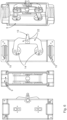
- the interconnecting part 9 interconnecting the two vacuum interrupters can be created out of two identical or similar blocks made from metal, that can carry the current flow through both vacuum interrupters arranged in series as well as provide mechanical support to the mechanism operating the push rod. At the same time, such construction enables better heat dissipation through its opening on two sides, see Fig. 6 and transfer the current from the middle connection between both the vacuum interrupters.
- This design in shown clearly in Fig. 6 , where each block of the interconnecting part 9 in effect has a side wall with two slots in, which can be mechanical reinforced by a suitable means 14.
- the interconnecting block when constructed is open on both sides, enabling cooling air flow and on one of the open sides the operating rod 11 enters the interconnection part 9 and is couple to the non-linear levers 22 of the lever system 12.
- One end of the non-linear levers are then pushed and pulled by the operating rod 11 as it translates sideways, for example when it is rotated by the actuator 8 and passes through a threaded bearing and the other ends of the non-linear levers 22 of the lever system 12 slide within the slots perpendicularly to the translation of the operating rod 11.
- the interconnection part 9 can consist of two identical halves mated together. Its main functionality is to ensure proper electrical connection of the two vacuum interrupters connected in series as the whole current is flowing through the both half parts.
- the side walls of the interconnection part 9 and its top and bottom structures provides a large surface area in the design of interconnection part 9, which enables very good heat dissipation and can be designed in addition as heat sink with ribs on the inner and/or outer side, or a suitable surface roughness, or pins, or holes for air flow or all of these.
- two half designs create an opening on the operating rod side as well as on the opposite side and therefore enables good air or gas flow through this connection, further improving the above mentioned heat dissipation for example energy can be transferred away from the circuit breaker under current load.
- the double VI design can use a symmetrical/mirrored arrangement of the two VIs 5, and were non-linear levers 22 used are also identical in shape and positioned in a symmetrical arrangement as well.
- the direction of force on the operating rod 11, i.e. the rod 11 is pushed to close the VIs 5 and pulled to open them.
- the non-linear lever arms 22 of the lever system 12 were arranged facing in the opposite direction, it can be arranged that the rod is pushed to open the VIs and pulled to close the Vis.
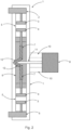
- Fig, 4 shows a cross section of one drive, and a 3D view of three drives of for example a three phase system, with Fig. 5 showing the drive in VIs connected (switched on) and VIs disconnected (switched off) states.
- Fig. 6 show non-linear levers 22 of a lever system 12, that translates or transforms movement of the operating rod 11 to the pushrods 7, providing necessary mechanical force, and adjusting the length of the movement which the pushrods need to take for proper on and off movement of vacuum interrupter contacts.
- the identical (mirrored) non-linear levers of the lever system 12 are connected to each vacuum interrupter 5 via the pushrod 7, simultaneous operation of both vacuum interrupters 5 is ensured. This is of importance for successful interruption.
- Both non-linear levers 22 of the operating system 12 are then connected to the operating rod 11 at the connection point/part 13.
- non-linear levers As detailed above, when we discuss both non-linear levers this refers to a non-linear lever driving the movable contact of one vacuum interrupter and one non-linear lever driving the movable contact of the other vacuum interrupter, but in fact each of these driving non-linear levers can be in the form of a pair of non-linear levers.
- the interconnection part 9 serves at the same time as a mechanical structure for the operating mechanism (non-linear levers). As the interconnection part 9 may not have sufficient mechanical strength on top of its electrical properties, additional mechanical reinforcement 14 (e.g. sliding bearing) parts might be necessary, but only in places of highest mechanical load or expected friction, i.e. in the closing or opening operation where the levers 12 are moving.
- Fig. 6 shows a specific "knee” or “elbow” shape design of the non-linear lever 22, that helps translating movement of the operating rod 11 to the pushrod 7, providing the necessary mechanical force and adjusting the length of the movement which the pushrods need to take for proper switching of VI contacts.
- Fig. 6 shows a specific "knee” or “elbow” shape design of the non-linear lever 22, that helps translating movement of the operating rod 11 to the pushrod 7, providing the necessary mechanical force and adjusting the length of the movement which the pushrods need to take for proper switching of VI contacts.
- the interconnection part 9 can be built from two blocks, which can also be termed half shells. It is to be noted that each separate half shell construction enables easy insertion of parts separately and thus ensures a smooth assembly process during production of the pole.
- Fig. 7a and 7b is show a cross-section and 3D representation respectively of an assembly design of the interconnection part 9 together with two VIs 5, pushrods 7, non-linear levers 22, operating rod 11 and their housing 1 as well as supporting insulators 10.
- Figs. 7a and 7b show a pole assembly design of the interconnection part 9 together with two vacuum interrupters 5, pushrods 7, non-linear levers 22 of the lever system 12, operating rod 11 from the actuator 8 and their housing 1.
- the housing 1 can also be constructed using the half shell principle as for the interconnection part 9, making the whole assembly very modular.
- a feature of this design is the fact that the housing shells 1 cover, at least partly, the interconnection part 9, and this helps increase the dielectric performance and further strengthens the mechanical robustness of the full assembly.
- a best dielectric performance can be achieved when the two housing shells 1 on each side are overlapping or connected (not shown in Fig. 7 ), to provide maximum dielectric coverage of the interconnection part 9 having full electric potential in case the two vacuum interrupters 5 are moved to an on position.
- Fig. 8 shows a cross section of the nonlinear mechanical movement of the drive assembly, showing movement of the operating rod 11 to move both push rods 7 of the movable contact of both vacuum interrupters inwards simultaneously.
- Fig. 9 shows the relationships between the dimensions of the non-linear lever design.
- the dimension (a) is made smaller than the dimension (b).
- the elbow/knee design enables that the needed stroke movement (c) of the operating rod 11 is shorter compared to that that would be necessary using linear levers, providing for a compact in-series dual VI design that also enables the contacts to be kept in place with a reduction in force and even with no force being required.
Landscapes
- High-Tension Arc-Extinguishing Switches Without Spraying Means (AREA)
Abstract
Description
- The present invention relates to a medium voltage or high voltage circuit breaker, a drive for a medium voltage or high voltage circuit breaker, and a medium voltage or high voltage switchgear.
- Vacuum interrupters are widely known in the industry, in the applications of low-; medium-; high- voltage circuit breakers.
-
Fig. 1 shows a standard design of a circuit breaker pole. The standard design of the circuit breaker pole has ahousing 1, which provides for the proper positioning of internal parts, theupper terminal 2 and thelower terminal 6 provide an interface to the outer environment. The circuit breaker also has a vacuum interrupter (VI) 5 and apushrod 7 transfers the movement of theactuator 8 into the VI. The VI 5 has one contact fixedcontact 3 and onemovable contact 4. - Movement of the
moveable contact 4 is achieved through thepush rod 7. Thefixed contact 3 is both mechanically and electrically connected to theupper terminal 2. Themoveable contact 4 is in electrical contact withlower contact 6. Mechanical fixation of themoveable contact 4 needs to allow for linear movement of this contact towards thefixed contact 3. Thehousing 1 is also used for improving the dielectric withstand of the whole interior assembly with respect to the surrounding electrical potentials. It is usually made of thermoplastic, duroplastic and/or thermoset material, which enables decreasing distances to the next phase(s) or grounded switchgear walls and provides for increasing creepage distances. - The success of these devices in medium voltage (MV) field has led to the desire for the extension of their applications towards higher voltage levels as well. Vacuum interrupters designed for higher voltage levels are feasible, but they are expensive and they are challenging to develop. When a VI is developed for high voltage applications, the resultant design is very bulky and significant design effort is needed to improve heat dissipation from such a bulky unit. This, together with lower production volumes applicable, become critical factors when deciding whether such VIs can be utilized in new developments. Furthermore, high voltage applications require large distance from fixed to moveable contact in the open state, resulting in a long path the
pushrod 7 needs to travel and subsequently in abig actuating mechanism 8 that needs to have sufficient power and has to drive thepushrod 7 in a long distance. - There is a need to address these issues.
- Therefore, it would be advantageous to have an improved medium voltage or high voltage circuit breaker.
- The object of the present invention is solved with the subject matter of the independent claims, wherein further embodiments are incorporated in the dependent claims.
- In a first aspect, there is provided a medium voltage or high voltage circuit breaker; comprising:
- a first terminal;
- a second terminal;
- a first vacuum interrupter;
- a second vacuum interrupter;
- an interconnection part;
- an actuator;
- an operating rod; and
- a lever system;
- It is to be noted that reference to an "end" of a non-linear lever arm does not require this to be right at the actual end, but can be towards or near the actual end.
- Thus, the second vacuum interrupter is connected in series with the first vacuum interrupter, and in a closed state current can flow from the first terminal to the second terminal when movable contacts of both vacuum interrupters are brought into contact with fixed contacts of both vacuum interrupters. And by using non-linear lever arms of a lever system to drive the movable contacts of the in series vacuum interrupters a compact design is provided, because the movement required by the operating rod is minimised.
- In an example, the first non-linear lever arm comprises a first arm part connected to a second arm part. The first arm part of the first non-linear lever arm is angled to the second arm part of the first non-linear lever arm. An end of the first arm part is the first end of the first non-linear lever arm coupled to the pushrod of the movable contact of the first vacuum interrupter at the first lever arm first end pivot point. An end of the second arm part is the second end of the first lever arm coupled to the operating rod at the centre pivot point.
- In an example, the second non-linear lever arm comprises a first arm part connected to a second arm part. The first arm part of the second non-linear lever arm is angled to the second arm part of the second non-linear lever arm. An end of the first arm part is the first end of the second non-linear lever arm coupled to the pushrod of the movable contact of the second vacuum interrupter at the second lever arm first end pivot point. An end of the second arm part is the second end of the second lever arm coupled to the operating rod at the centre pivot point.
- In an example, a length of the first arm part of the first non-linear lever arm between the first end pivot point and the connection with the second arm part of the first non-linear lever arm is less than a length of the second arm part of the first non-linear lever arm between the centre pivot point and the connection with the first arm part of the first non-linear lever arm.
- In an example, a length of the first arm part of the second non-linear lever arm between the first end pivot point and the connection with the second arm part of the second non-linear lever arm is less than a length of the second arm part of the second non-linear lever arm between the centre pivot point and the connection with the first arm part of the second non-linear lever arm.
- In an example, the first arm part of the first non-linear lever arm is angled to the second arm part of the first non-linear lever arm at an obtuse angle.
- In an example, the first arm part of the second non-linear lever arm is angled to the second arm part of the second non-linear lever arm at an obtuse angle.
- In an example, the first arm part of the first non-linear lever arm is angled to the second arm part of the first non-linear lever arm at an angle substantially equal to 90 degrees.
- In an example, the first arm part of the second non-linear lever arm is angled to the second arm part of the second non-linear lever arm at an angle substantially equal to 90 degrees.
- In an example, the second non-linear lever arm is a mirror image of the first non-linear lever arm.
- In an example, the second non-linear lever arm is not a mirror image of the first non-linear lever arm.
- In an example, the first vacuum interrupter is of a different design to the second vacuum interrupter.
- In an example, the interconnection part is configured to be in electrical connection with the movable contact of the first vacuum interrupter and the interconnection part is configured to be in electrical connection with the movable contact of the second vacuum interrupter during at least part of the transition from the open state to the closed state.
- In an example, in a transition from the closed state to the open state the actuator is configured to move the operating rod to move the second end of the first non-linear lever arm and the second end of the second non-linear lever arm such that the part at the first end of the first non-linear lever arm and the part at the first end of the second non-linear lever arm move simultaneously within their corresponding slots towards one another or with respect to their corresponding bearings towards one another.
- In a second aspect, there is provided a drive for a medium voltage or high voltage circuit breaker. The circuit breaker comprises a first terminal, a second terminal, a first vacuum interrupter, a second vacuum interrupter. The first terminal is electrically connected to a fixed contact of the first vacuum interrupter, and the second terminal is electrically connected to a fixed contact of the second vacuum interrupter. Regarding the drive itself this comprises:
- an interconnection part;
- an actuator;
- an operating rod ; and
- a lever system.
- In an example, the first non-linear lever arm comprises a first arm part connected to a second arm part. The first arm part of the first non-linear lever arm is angled to the second arm part of the first non-linear lever arm. An end of the first arm part is the first end of the first non-linear lever arm coupled to the pushrod of the movable contact of the first vacuum interrupter at the first lever arm first end pivot point. An end of the second arm part is the second end of the first lever arm coupled to the operating rod at the centre pivot point.
- In an example, the second non-linear lever arm comprises a first arm part connected to a second arm part. The first arm part of the second non-linear lever arm is angled to the second arm part of the second non-linear lever arm. An end of the first arm part is the first end of the second non-linear lever arm coupled to the pushrod of the movable contact of the second vacuum interrupter at the second lever arm first end pivot point. An end of the second arm part is the second end of the second lever arm coupled to the operating rod at the centre pivot point.
- In an example, a length of the first arm part of the first non-linear lever arm between the first end pivot point and the connection with the second arm part of the first non-linear lever arm is less than a length of the second arm part of the first non-linear lever arm between the centre pivot point and the connection with the first arm part of the first non-linear lever arm.
- In an example, a length of the first arm part of the second non-linear lever arm between the first end pivot point and the connection with the second arm part of the second non-linear lever arm is less than a length of the second arm part of the second non-linear lever arm between the centre pivot point and the connection with the first arm part of the second non-linear lever arm.
- In an example, the first arm part of the first non-linear lever arm is angled to the second arm part of the first non-linear lever arm at an obtuse angle.
- In an example, the first arm part of the second non-linear lever arm is angled to the second arm part of the second non-linear lever arm at an obtuse angle.
- In an example, the first arm part of the first non-linear lever arm is angled to the second arm part of the first non-linear lever arm at an angle substantially equal to 90 degrees.
- In an example, the first arm part of the second non-linear lever arm is angled to the second arm part of the second non-linear lever arm at an angle substantially equal to 90 degrees.
- In an example, the second non-linear lever arm is a mirror image of the first non-linear lever arm.
- In an example, the second non-linear lever arm is not a mirror image of the first non-linear lever arm.
- In a third aspect, there is provided a medium voltage or high voltage switchgear comprising at least one circuit breaker according to the first aspect.
- Thus, a design is provided with an interconnection part, which as part of a drive, and the interconnecting part is a part interconnecting two vacuum interrupters (Vis) that are electrically connected in series. This interconnection part interconnecting the two VIs is designed not only for current carrying functionality, but at the same time provides for improved heat exchange and provides for mechanical fixation of the movable parts like current carrying flexible part or sliding current connection to the movable contacts. Also, the interconnecting part and provides for support means for a lever system that is used to move the movable contacts, and where the lever system uses non-linear lever arms to reduce the required stroke of an operating rod and reduce the size of the circuit breaker. The circuit breaker with the drive can be manufactured in this way, and also two existing vacuum interrupters can be coupled together by the interconnecting part, as part of a new drive, in order to provide for increased voltage capability and/or capability at an existing voltage with faster switching operation in an overall size that is minimized. A new drive design has a lever system that connects the pole actuator with pushrods of the two series connected vacuum interrupters, with non-linear lever arms. Using non-linear lever arms with an "elbow" or "knee" shape provides for a decreasing manipulation space needed to move the operating rod and/or adjust the forces needed for proper operation of the vacuum interrupters. Also, a housing can surround the whole to improve the dielectric withstand between two phases/poles as well as for the higher mechanical strength.
- The above aspects and examples will become apparent from and be elucidated with reference to the embodiments described hereinafter.
- Exemplary embodiments will be described in the following with reference to the following drawings:
-
Fig. 1 shows an example of a standard design of a single phase circuit breaker; -
Fig. 2 shows an example of a design of a medium voltage or high voltage circuit breaker using linear lever arms; -
Fig. 3 shows an example of three phase system using design of a medium voltage or high voltage circuit breaker using linear lever arms; -
Fig. 4 shows an example of a design of a drive for a medium voltage or high voltage circuit breaker using non-linear lever arms; -
Fig. 5 shows an example of a design of a drive for a medium voltage or high voltage circuit breaker using non-linear lever arms; -
Fig. 6 shows an example of a design of a drive for a medium voltage or high voltage circuit breaker using non-linear lever arms and with connections shown to vacuum interrupters at both ends; -
Fig. 7 shows examples of a new design of a medium voltage or high voltage circuit breaker; -
Fig. 8 shows an example of a design of a drive for a medium voltage or high voltage circuit breaker using non-linear lever arms, and -
Fig. 9 shows an example of a design of a drive for a medium voltage or high voltage circuit breaker using non-linear lever arms - A new medium voltage or high voltage circuit breaker is now described along with the new drive for a medium voltage or high voltage circuit breaker. In the following a medium voltage or high voltage circuit breaker is described with two vacuum interrupters in series with an interconnection part, as part of a drive, connecting them. The current new development can be utilized with more than two vacuum interrupters in series, with interconnection parts connecting adjacent vacuum interrupters.
- In an example, a medium voltage or high voltage circuit breaker comprises a
first terminal 2, asecond terminal 6, afirst vacuum interrupter 5, asecond vacuum interrupter 5, aninterconnection part 9, anactuator 8. an operatingrod 11, and alever system 12. The first terminal is electrically connected to afixed contact 3 of the first vacuum interrupter. The second terminal is electrically connected to afixed contact 3 of the second vacuum interrupter. The interconnection part is configured to be in electrical connection with amovable contact 4 of the first vacuum interrupter and the interconnection part is configured to be in electrical connection with amovable contact 4 of the second vacuum interrupter, and the interconnection part is configured to provide a current path between the movable contacts. Thus, upon activation the movable contacts of both vacuum interrupters are moved towards the respective fixed contacts until in a closed state the movable contacts are in contact with the fixed contacts. There is then a current path from the first terminal to the second terminal via the first vacuum interrupter, the interconnection part, and the second vacuum interrupter. A first end of a firstnon-linear lever arm 22 of the lever system is coupled to apushrod 7 of the movable contact of the first vacuum interrupter at a first lever arm first end pivot point, and a second end of the first lever arm is coupled to the operating rod at a centre pivot point. A first end of a secondnon-linear lever arm 22 of the lever system is coupled to apushrod 7 of the movable contact of the second vacuum interrupter at a second lever arm first end pivot point, and a second end of the second lever arm is coupled to the operating rod at the centre pivot point. A part at the first end of the first non-linear lever arm is supported by the interconnection part and can slide linearly within a slot of the interconnection part or a part at the first end of the first non-linear lever arm is supported by the interconnection part and can move linearly with respect to a bearing of the interconnection part. A part at the first end of the second non-linear lever arm is supported by the interconnection part and can slide linearly within a slot of the interconnection part or a part at the first end of the second non-linear lever arm is supported by the interconnection part and can move linearly with respect to a bearing of the interconnection part. This is shown clearly in the Figures, where in specific embodiments shown the first and second non-linear lever arms are each actually doubled with an axle going through both sets at one end and attached to the operating rod enabling the first and second non-linear lever arm pairs to rotate with respect to the operating rod. At the other end each pair of the non-linear lever arms has another axle that has ends that go into slots in opposite walls of the interconnection part enabling the ends of the non-linear lever arms to translate upwards and downwards as the non-linear lever arms are angled through the other ends of the lever arms being pulled sideways. The ends of the non-linear lever arms moving upwards and downwards are coupled to the ends movable contacts viapushrods 7, enabling the non-linear lever arms to move the movable contacts towards and away from the fixed contacts simultaneously. Thepush rod 7, thenon-linear lever arms 22 of thelever system 12 and the operatingrod 11 can all be of an insulating material (or one of them can be) in order that theactuator 8 is electrically isolated from the movable contacts. In a transition from an open state to the closed state the actuator is configured to move the operating rod to move the second end of the first non-linear lever arm and the second end of the second non-linear lever arm such that the part at the first end of the first non-linear lever arm and the part at the first end of the second non-linear lever arm move simultaneously within their corresponding slots away from one another or with respect to their corresponding bearings away from one another. - In an example, the first vacuum interrupter is identical to the second vacuum interrupter.
- According to an example, the first non-linear lever arm comprises a first arm part connected to a second arm part, and the first arm part of the first non-linear lever arm is angled to the second arm part of the first non-linear lever arm. An end of the first arm part is the first end of the first non-linear lever arm coupled to the pushrod of the movable contact of the first vacuum interrupter at the first lever arm first end pivot point, and an end of the second arm part is the second end of the first lever arm coupled to the operating rod at the centre pivot point. The second non-linear lever arm comprises a first arm part connected to a second arm part, and the first arm part of the second non-linear lever arm is angled to the second arm part of the second non-linear lever arm. An end of the first arm part is the first end of the second non-linear lever arm coupled to the pushrod of the movable contact of the second vacuum interrupter at the second lever arm first end pivot point, and an end of the second arm part is the second end of the second lever arm coupled to the operating rod at the centre pivot point.
- According to an example, a length (a) of the first arm part of the first non-linear lever arm between the first end pivot point and the connection with the second arm part of the first non-linear lever arm is less than a length (b) of the second arm part of the first non-linear lever arm between the centre pivot point and the connection with the first arm part of the first non-linear lever arm. Also, a length (a) of the first arm part of the second non-linear lever arm between the first end pivot point and the connection with the second arm part of the second non-linear lever arm is less than a length (b) of the second arm part of the second non-linear lever arm between the centre pivot point and the connection with the first arm part of the second non-linear lever arm.
- According to an example, the first arm part of the first non-linear lever arm is angled to the second arm part of the first non-linear lever arm at an obtuse angle, and the first arm part of the second non-linear lever arm is angled to the second arm part of the second non-linear lever arm at an obtuse angle.
- According to an example, the first arm part of the first non-linear lever arm is angled to the second arm part of the first non-linear lever arm at an angle substantially equal to 90 degrees, and the first arm part of the second non-linear lever arm is angled to the second arm part of the second non-linear lever arm at an angle substantially equal to 90 degrees.
- According to an example, the second non-linear lever arm is a mirror image of the first non-linear lever arm.
- According to an example, the second non-linear lever arm is not a mirror image of the first non-linear lever arm.
- According to an example, the first vacuum interrupter is of a different design to the second vacuum interrupter.
In an example, the part at the first end of the first non-linear lever arm and the part at the first end of the second non-linear lever arm move simultaneously within their corresponding slots away from one another over the same distance or with respect to their corresponding bearings away from one another over the same distance. - Thus, the ends of the non-linear lever arms can move within slots as shown in the figures, however the ends can move with respect to or in bearings or similar that are integrated into the interconnection part, which can lead to a reduction in friction with respect to movement in a slot.
- In an example, the part at the first end of the first non-linear lever arm and the part at the first end of the second non-linear lever arm move simultaneously within their corresponding slots away from one another over a different distance or with respect to their corresponding bearings away from one another over the different distance.
- In an example, the part at the first end of the first non-linear lever arm and the part at the first end of the second non-linear lever arm move simultaneously within their corresponding slots away from one another at different velocities or with respect to their corresponding bearings away from one another over at different velocities.
- Thus, the ends of the non-linear lever arms can move within slots or with respect to bearings or similar that are integrated into the interconnection part, to move the movable contacts over different distances to obtain different final gaps between the movable and fixed contacts for each vacuum interrupter and move the contacts at different velocities.
- According to an example, the interconnection part is configured to be in electrical connection with the movable contact of the first vacuum interrupter and the interconnection part is configured to be in electrical connection with the movable contact of the second vacuum interrupter during at least part of the transition from the open state to the closed state.
- As shown in
Fig. 6 , this can be provided via "sliding" current carryingelements 15, such as a spiral contact or multilamellar, or contact band that can be fixed between the movable stem of the movable contact and theinterconnection part 9. Thus, a drive rod of amovable contact 4, that is coupled to apush rod 7, can slide within the sliding current carryingelements 15 and there is an electrical connection from the stem of themovable contact 4 to theinterconnection part 9. The electrical connection can be always established, such that the movable contact is always in electrical connection with the interconnection part, but it can be only in electrical connection towards the end of its drive as it approaches the fixed contact and when it is in contact with the fixed contact. - In an example, the interconnection part is configured to be in electrical connection with the movable contact of the first vacuum interrupter and the interconnection part is configured to be in electrical connection with the movable contact of the second vacuum interrupter.
- According to an example, in a transition from the closed state to the open state the actuator is configured to move the operating rod to move the second end of the first non-linear lever arm and the second end of the second non-linear lever arm such that the part at the first end of the first non-linear lever arm and the part at the first end of the second non-linear lever arm move simultaneously within their corresponding slots towards one another or with respect to their corresponding bearings towards one another.
- In an example, the part at the first end of the first non-linear lever arm and the part at the first end of the second non-linear lever arm move simultaneously within their corresponding slots towards one another over the same distance or with respect to their corresponding bearings towards one another over the same distance.
- In an example, the interconnection part is configured to be in electrical connection with the movable contact of the first vacuum interrupter and the interconnection part is configured to be in electrical connection with the movable contact of the second vacuum interrupter during at least part of the transition from the closed state to the open state.
- In an example, the current path between the movable contacts is provided by at least one wall of the interconnection part.
- In an example, one or more of the at least one wall of the interconnection part comprises ribs on the inner side and/or on the outer side.
- In an example, the interconnection part is open on a first side.
- In an example, the interconnection part is open on a second side opposite to the first side.
- In an example, a mounting between the actuator and the housing comprises at least one supporting and insulating
mean 10. - A medium voltage or high voltage switchgear can comprise one or more of such a circuit breaker as described above.
- An exemplar drive for a medium voltage or high voltage circuit breaker is now described. To better understand the drive, the circuit breaker is first described. The circuit breaker comprises a
first terminal 2, asecond terminal 6, afirst vacuum interrupter 5, asecond vacuum interrupter 5, here the first terminal is electrically connected to afixed contact 3 of the first vacuum interrupter, and the second terminal is electrically connected to afixed contact 3 of the second vacuum interrupter. The drive itself comprises aninterconnection part 9, anactuator 8, an operatingrod 11, and alever system 12. The interconnection part is configured to be in electrical connection with amovable contact 4 of the first vacuum interrupter and the interconnection part is configured to be in electrical connection with amovable contact 4 of the second vacuum interrupter, and the interconnection part is configured to provide a current path between the movable contacts. A first end of a firstnon-linear lever arm 22 of the lever system is configured to couple to apushrod 7 of the movable contact of the first vacuum interrupter at a first lever arm first end pivot point, and a second end of the first lever arm is coupled to the operating rod at a centre pivot point. A first end of a secondnon-linear lever arm 22 of the lever system is configured to couple to apushrod 7 of the movable contact of the second vacuum interrupter at a second lever arm first end pivot point, and a second end of the second lever arm is coupled to the operating rod at the centre pivot point. A part at the first end of the first non-linear lever arm is supported by the interconnection part and can slide linearly within a slot of the interconnection part or a part at the first end of the first non-linear lever arm is supported by the interconnection part and can move linearly with respect to a bearing of the interconnection part. A part at the first end of the second non-linear lever arm is supported by the interconnection part and can slide linearly within a slot of the interconnection part or a part at the first end of the second non-linear lever arm is supported by the interconnection part and can move linearly with respect to a bearing of the interconnection part. In a first transition the actuator is configured to move the operating rod in a first direction to move the second end of the first lever arm and the second end of the second lever arm such that the part at the first end of the first lever arm and the part at the first end of the second lever arm move simultaneously within their corresponding slots away from one another. In a second transition the actuator is configured to move the operating rod in a second direction opposite to the first direction to move the second end of the first non-linear lever arm and the second end of the second non-linear lever arm such that the part at the first end of the first non-linear lever arm and the part at the first end of the second non-linear lever arm move simultaneously within their corresponding slots towards one another or with respect to their corresponding bearings away from one another. - In an example, the first vacuum interrupter is identical to the second vacuum interrupter.
- According to an example, the first non-linear lever arm comprises a first arm part connected to a second arm part, and the first arm part of the first non-linear lever arm is angled to the second arm part of the first non-linear lever arm. An end of the first arm part is the first end of the first non-linear lever arm coupled to the pushrod of the movable contact of the first vacuum interrupter at the first lever arm first end pivot point, and an end of the second arm part is the second end of the first lever arm coupled to the operating rod at the centre pivot point. The second non-linear lever arm comprises a first arm part connected to a second arm part, and the first arm part of the second non-linear lever arm is angled to the second arm part of the second non-linear lever arm. An end of the first arm part is the first end of the second non-linear lever arm coupled to the pushrod of the movable contact of the second vacuum interrupter at the second lever arm first end pivot point, and an end of the second arm part is the second end of the second lever arm coupled to the operating rod at the centre pivot point.
- According to an example, a length (a) of the first arm part of the first non-linear lever arm between the first end pivot point and the connection with the second arm part of the first non-linear lever arm is less than a length (b) of the second arm part of the first non-linear lever arm between the centre pivot point and the connection with the first arm part of the first non-linear lever arm. Also, a length (a) of the first arm part of the second non-linear lever arm between the first end pivot point and the connection with the second arm part of the second non-linear lever arm is less than a length (b) of the second arm part of the second non-linear lever arm between the centre pivot point and the connection with the first arm part of the second non-linear lever arm.
- According to an example, the first arm part of the first non-linear lever arm is angled to the second arm part of the first non-linear lever arm at an obtuse angle, and the first arm part of the second non-linear lever arm is angled to the second arm part of the second non-linear lever arm at an obtuse angle.
- According to an example, the first arm part of the first non-linear lever arm is angled to the second arm part of the first non-linear lever arm at an angle substantially equal to 90 degrees, and the first arm part of the second non-linear lever arm is angled to the second arm part of the second non-linear lever arm at an angle substantially equal to 90 degrees.
- It is to be noted that the non-linear lever arms could be in the form of a triangular-like shape, where the sides of the triangle are of different lengths (a and b). This can provide for extra robustness, with the functionality of such triangle-like "levers" equivalent to that discussed for the non-linear lever arms.
- According to an example, the second non-linear lever arm is a mirror image of the first non-linear lever arm.
- According to an example, the second non-linear lever arm is not a mirror image of the first non-linear lever arm.
- In an example, the part at the first end of the first non-linear lever arm and the part at the first end of the second non-linear lever arm move simultaneously within their corresponding slots away from one another over the same distance or with respect to their corresponding bearings away from one another over the same distance.
- In an example, the part at the first end of the first non-linear lever arm and the part at the first end of the second non-linear lever arm move simultaneously within their corresponding slots away from one another over a different distance or with respect to their corresponding bearings away from one another over the different distance.
- In an example, the part at the first end of the first non-linear lever arm and the part at the first end of the second non-linear lever arm move simultaneously within their corresponding slots away from one another at different velocities or with respect to their corresponding bearings away from one another over at different velocities.
- In an example, the interconnection part is configured to be in electrical connection with the movable contact of the first vacuum interrupter and the interconnection part is configured to be in electrical connection with the movable contact of the second vacuum interrupter during at least part of the transition from the open state to the closed state.
- In an example, the part at the first end of the first non-linear lever arm and the part at the first end of the second non-linear lever arm move simultaneously within their corresponding slots towards one another over the same distance or with respect to their corresponding bearings towards one another over the same distance.
- In an example, the interconnection part is configured to be in electrical connection with the movable contact of the first vacuum interrupter and the interconnection part is configured to be in electrical connection with the movable contact of the second vacuum interrupter during at least part of the transition from the closed state to the open state.
- In an example, interconnection part is configured such that the current path between the movable contacts is provided by at least one wall of the interconnection part.
- In an example, one or more of the at least one wall of the interconnection part comprises ribs on the inner side and/or on the outer side.
- In an example, the interconnection part is open on a first side.
- In an example, the interconnection part is open on a second side opposite to the first side.
- The above drive can be coupled with two vacuum interrupters as a circuit breaker is first being manufactured. However, it is possible to customize two existing vacuum interrupters with such a connecting drive positioned in series with the vacuum interrupters, to both drive the movable contacts simultaneously and provide a current path through the entire system in a closed state.
- The new medium voltage or high voltage circuit breaker and the new drive for a medium voltage or high voltage circuit breaker are now described in specific detail, where reference is made to
Figs. 2-9 . It is to be noted, that for reasons of simplicity of representationFigs. 2 and3 show a lever system (of the new drive) with linear lever arms, withFigs. 4-9 showing a lever system (of the new drive) withnon-linear lever arms 22. - In comparison to a single vacuum interrupter structure shown in
Fig. 1 , the new double vacuum interrupter circuit breaker design can use twoidentical vacuum interrupters 5, that interconnect their current carrying parts through aspecific part 9 called an interconnection part. The vacuum interrupters, together with their terminals and housing can also be termed poles. Mechanical fixation of all the other parts of both poles within the switchgear or other tanks, can be either done by adaptation of theirhousing 1, by fixing at theupper terminal 2 andlower terminal 6 or preferably both, i.e. housing as well as terminal fixation. - Depending on a
specific actuator 8 and/orpushrod 7 design, thehousing 1 may need to be supported by some supporting and insulatingmeans 10, to withstand the mechanical loads originating from theactuator 8 as well as to provide sufficient insulating distance between terminals and grounded parts of theactuator 8 or surrounding parts. - Connection of the operating
rod 11 driven by an actuator is translated by thenon-linear levers 22 of alever system 12 into the movement ofpushrods 7, that are moving themovable contacts 4 of thevacuum interrupters 5. Thelever system 12 has identical first and secondnon-linear lever arms 22 that are each attached to the operating rod at one end and at the other end the respective lever arms are couple to themovable contacts 4 viarespective push rods 7. Here identical actual means that they are mirror images of each other. - The two identical VIs 5 can both be designed for nearly half rated voltage compared to a single vacuum interrupter design, but with the same short circuit interruption current performance as a single vacuum interrupter deign. Therefore, the advantage of such a structure is, that series combination of two existing vacuum interrupters can be used for a double voltage level, without the necessity to utilize one higher voltage vacuum interrupter, what could require to design a new single vacuum interrupter for a particular rated voltage level.
- Another advantage of the double vacuum interrupter structure is that the distance between the fixed and the movable contacts of the vacuum interrupters can be half in each vacuum interrupter, compared to a distance needed in the situation of a single vacuum interrupter concept. Therefore, considering the same actuator design used in both cases, the opening speed for the two vacuum interrupter design will be much faster because of two gaps will open at the same time with same speed.
- By having
non-linear lever arms 22 rather than linear lever arms, a rotation of the non-linear lever arm as it is pushed or pulled by the operating rod leads to an increased linear translation of the end of the non-linear lever arm in its slot, and to an increased movement of the movable contacts. Thus, the operatingrod 11 does not need to be moved so far, as regards if the lever arms were linear, and the operating rod can be shorter. Also the design of the non-linear levers not only decreases the distance required for the operating rod to move between open and closed position of the vacuum interrupters (Vis), but they create non-linearity of the switching force needed for optimum VIs switching. - The interconnecting
part 9 interconnecting the two vacuum interrupters can be created out of two identical or similar blocks made from metal, that can carry the current flow through both vacuum interrupters arranged in series as well as provide mechanical support to the mechanism operating the push rod. At the same time, such construction enables better heat dissipation through its opening on two sides, seeFig. 6 and transfer the current from the middle connection between both the vacuum interrupters. This design in shown clearly inFig. 6 , where each block of the interconnectingpart 9 in effect has a side wall with two slots in, which can be mechanical reinforced by asuitable means 14. The interconnecting block when constructed is open on both sides, enabling cooling air flow and on one of the open sides the operatingrod 11 enters theinterconnection part 9 and is couple to thenon-linear levers 22 of thelever system 12. One end of the non-linear levers are then pushed and pulled by the operatingrod 11 as it translates sideways, for example when it is rotated by theactuator 8 and passes through a threaded bearing and the other ends of thenon-linear levers 22 of thelever system 12 slide within the slots perpendicularly to the translation of the operatingrod 11. - Thus, the
interconnection part 9 can consist of two identical halves mated together. Its main functionality is to ensure proper electrical connection of the two vacuum interrupters connected in series as the whole current is flowing through the both half parts. The side walls of theinterconnection part 9 and its top and bottom structures provides a large surface area in the design ofinterconnection part 9, which enables very good heat dissipation and can be designed in addition as heat sink with ribs on the inner and/or outer side, or a suitable surface roughness, or pins, or holes for air flow or all of these. Furthermore, two half designs create an opening on the operating rod side as well as on the opposite side and therefore enables good air or gas flow through this connection, further improving the above mentioned heat dissipation for example energy can be transferred away from the circuit breaker under current load. - As shown in the
Figs, 4-9 , the double VI design can use a symmetrical/mirrored arrangement of the two VIs 5, and werenon-linear levers 22 used are also identical in shape and positioned in a symmetrical arrangement as well. In the designs shown the direction of force on the operatingrod 11, i.e. therod 11 is pushed to close the VIs 5 and pulled to open them. However, if thenon-linear lever arms 22 of thelever system 12 were arranged facing in the opposite direction, it can be arranged that the rod is pushed to open the VIs and pulled to close the Vis. -
Fig, 4 shows a cross section of one drive, and a 3D view of three drives of for example a three phase system, withFig. 5 showing the drive in VIs connected (switched on) and VIs disconnected (switched off) states. - As detailed above
Fig. 6 show non-linear levers 22 of alever system 12, that translates or transforms movement of the operatingrod 11 to thepushrods 7, providing necessary mechanical force, and adjusting the length of the movement which the pushrods need to take for proper on and off movement of vacuum interrupter contacts. As the identical (mirrored) non-linear levers of thelever system 12 are connected to eachvacuum interrupter 5 via thepushrod 7, simultaneous operation of bothvacuum interrupters 5 is ensured. This is of importance for successful interruption. Bothnon-linear levers 22 of theoperating system 12 are then connected to the operatingrod 11 at the connection point/part 13. As detailed above, when we discuss both non-linear levers this refers to a non-linear lever driving the movable contact of one vacuum interrupter and one non-linear lever driving the movable contact of the other vacuum interrupter, but in fact each of these driving non-linear levers can be in the form of a pair of non-linear levers. Theinterconnection part 9 serves at the same time as a mechanical structure for the operating mechanism (non-linear levers). As theinterconnection part 9 may not have sufficient mechanical strength on top of its electrical properties, additional mechanical reinforcement 14 (e.g. sliding bearing) parts might be necessary, but only in places of highest mechanical load or expected friction, i.e. in the closing or opening operation where thelevers 12 are moving. -
Fig. 6 shows a specific "knee" or "elbow" shape design of thenon-linear lever 22, that helps translating movement of the operatingrod 11 to thepushrod 7, providing the necessary mechanical force and adjusting the length of the movement which the pushrods need to take for proper switching of VI contacts. As the samenon-linear levers 22 are connected to each VI 5 andpushrod 7, simultaneous operation of both VIs 5 is ensured. Bothnon-linear levers 22 are then connected to the operatingrod 11 at the connection point/part 13 - also termed the centre connection point. - As detailed above, the
interconnection part 9 can be built from two blocks, which can also be termed half shells. It is to be noted that each separate half shell construction enables easy insertion of parts separately and thus ensures a smooth assembly process during production of the pole. -
Fig. 7a and 7b is show a cross-section and 3D representation respectively of an assembly design of theinterconnection part 9 together with two VIs 5,pushrods 7,non-linear levers 22, operatingrod 11 and theirhousing 1 as well as supportinginsulators 10. - In more details,
Figs. 7a and 7b show a pole assembly design of theinterconnection part 9 together with twovacuum interrupters 5,pushrods 7,non-linear levers 22 of thelever system 12, operatingrod 11 from theactuator 8 and theirhousing 1. Thehousing 1 can also be constructed using the half shell principle as for theinterconnection part 9, making the whole assembly very modular. A feature of this design is the fact that thehousing shells 1 cover, at least partly, theinterconnection part 9, and this helps increase the dielectric performance and further strengthens the mechanical robustness of the full assembly. A best dielectric performance can be achieved when the twohousing shells 1 on each side are overlapping or connected (not shown inFig. 7 ), to provide maximum dielectric coverage of theinterconnection part 9 having full electric potential in case the twovacuum interrupters 5 are moved to an on position. - An advantage is provided by the entire mechanical chain, because the push mechanical operation will be transferred to close the breaker. The non-linear mechanical chain leads to less space needed in the shown "elbow" / "knee" arrangement, where the stroke of the operating
rod 11 is smaller to move both thepushrods 7 in closed- or open- position. The character of such an arrangement needs some forces to keep the contacts (and pushrod) in the closed position. That will be different in case the construction of the elbow/knee design will be used according to what is shown inFig. 7 . Here the forces are kept inside the elbow/knee in the closed position, and a permanent force from the operating rod is no longer needed. -
Fig. 8 shows a cross section of the nonlinear mechanical movement of the drive assembly, showing movement of the operatingrod 11 to move bothpush rods 7 of the movable contact of both vacuum interrupters inwards simultaneously. -
Fig. 9 shows the relationships between the dimensions of the non-linear lever design. In order to provide the biggest benefit from such a construction of the lever and decrease distance (c), which the operating rod needs to move, the dimension (a) is made smaller than the dimension (b). Thus, the elbow/knee design enables that the needed stroke movement (c) of the operatingrod 11 is shorter compared to that that would be necessary using linear levers, providing for a compact in-series dual VI design that also enables the contacts to be kept in place with a reduction in force and even with no force being required. - The description above has centred on the example of identical VIs 5, and with mirror image
non-linear lever arms 22. However, the VIs can be different and the lever arms can be different to each other. Thus, during opening a gap between contacts of the first VI can be opened at a lower velocity than a gap between contacts of the second VI and the final gap between contacts can be different between the contacts of the two Vis. This enables that a smaller gap distance can be used for obtaining a good arc control at contact gap distance of for example up to 25-30mm and the other contact gap distance can for example be up to 50mm. - Also, with such an asymmetrical design there exists the opportunity to use the one vacuum interrupter gap which will take a higher voltage withstand, where here the VI with the higher gap distance will be placed. This can be done based on the natural asymmetry of the voltage share between both the VI's.
- Additionally, there also exists the opportunity to place on the higher gap side a vacuum interrupter equipped with AMF contact type and on the one with the smaller gap a vacuum interrupter equipped with TMF contact type.
- By using a different and nonlinear mechanical movement of both the contact gaps, with for example contacts of different contact types (AMF/TMF) enables a maximization of performance of current control, whilst avoiding contact deterioration.
- While the invention has been illustrated and described in detail in the drawings and foregoing description, such illustration and description are to be considered illustrative or exemplary and not restrictive. The invention is not limited to the disclosed embodiments. Other variations to the disclosed embodiments can be understood and effected by those skilled in the art in practicing a claimed invention, from a study of the drawings, the disclosure, and the dependent claims.
Claims (17)
- A medium voltage or high voltage circuit breaker; comprising:- a first terminal (2);- a second terminal (6);- a first vacuum interrupter (5);- a second vacuum interrupter (5);- an interconnection part (9);- an actuator (8);- an operating rod (11); and- a lever system (12);wherein the first terminal is electrically connected to a fixed contact (3) of the first vacuum interrupter, and wherein the second terminal is electrically connected to a fixed contact (3) of the second vacuum interrupter;wherein the interconnection part is configured to be in electrical connection with a movable contact (4) of the first vacuum interrupter and the interconnection part is configured to be in electrical connection with a movable contact (4) of the second vacuum interrupter, and wherein the interconnection part is configured to provide a current path between the movable contacts;wherein a first end of a first non-linear lever arm (22) of the lever system is coupled to a pushrod (7) of the movable contact of the first vacuum interrupter at a first lever arm first end pivot point, and wherein a second end of the first lever arm is coupled to the operating rod at a centre pivot point;wherein a first end of a second non-linear lever arm (22) of the lever system is coupled to a pushrod (7) of the movable contact of the second vacuum interrupter at a second lever arm first end pivot point, and wherein a second end of the second lever arm is coupled to the operating rod at the centre pivot point;wherein a part at the first end of the first non-linear lever arm is supported by the interconnection part and can slide linearly within a slot of the interconnection part or a part at the first end of the first non-linear lever arm is supported by the interconnection part and can move linearly with respect to a bearing of the interconnection part;wherein a part at the first end of the second non-linear lever arm is supported by the interconnection part and can slide linearly within a slot of the interconnection part or a part at the first end of the second non-linear lever arm is supported by the interconnection part and can move linearly with respect to a bearing of the interconnection part; andwherein in a transition from an open state to the closed state the actuator is configured to move the operating rod to move the second end of the first non-linear lever arm and the second end of the second non-linear lever arm such that the part at the first end of the first non-linear lever arm and the part at the first end of the second non-linear lever arm move simultaneously within their corresponding slots away from one another or with respect to their corresponding bearings away from one another.
- Circuit breaker according to claim 1, wherein the first non-linear lever arm comprises a first arm part connected to a second arm part, wherein the first arm part of the first non-linear lever arm is angled to the second arm part of the first non-linear lever arm, wherein an end of the first arm part is the first end of the first non-linear lever arm coupled to the pushrod of the movable contact of the first vacuum interrupter at the first lever arm first end pivot point, and wherein an end of the second arm part is the second end of the first lever arm coupled to the operating rod at the centre pivot point; and wherein the second non-linear lever arm comprises a first arm part connected to a second arm part, wherein the first arm part of the second non-linear lever arm is angled to the second arm part of the second non-linear lever arm, wherein an end of the first arm part is the first end of the second non-linear lever arm coupled to the pushrod of the movable contact of the second vacuum interrupter at the second lever arm first end pivot point, and wherein an end of the second arm part is the second end of the second lever arm coupled to the operating rod at the centre pivot point.
- Circuit breaker according to claim 2, wherein a length (a) of the first arm part of the first non-linear lever arm between the first end pivot point and the connection with the second arm part of the first non-linear lever arm is less than a length (b) of the second arm part of the first non-linear lever arm between the centre pivot point and the connection with the first arm part of the first non-linear lever arm; and wherein a length (a) of the first arm part of the second non-linear lever arm between the first end pivot point and the connection with the second arm part of the second non-linear lever arm is less than a length (b) of the second arm part of the second non-linear lever arm between the centre pivot point and the connection with the first arm part of the second non-linear lever arm.
- Circuit breaker according to any of claims 2-3, wherein the first arm part of the first non-linear lever arm is angled to the second arm part of the first non-linear lever arm at an obtuse angle; and wherein the first arm part of the second non-linear lever arm is angled to the second arm part of the second non-linear lever arm at an obtuse angle.
- Circuit breaker according to any of claims 2-3, wherein the first arm part of the first non-linear lever arm is angled to the second arm part of the first non-linear lever arm at an angle substantially equal to 90 degrees; and wherein the first arm part of the second non-linear lever arm is angled to the second arm part of the second non-linear lever arm at an angle substantially equal to 90 degrees.
- Circuit breaker according to any of claims 1-5, wherein the second non-linear lever arm is a mirror image of the first non-linear lever arm.
- Circuit breaker according to any of claims 1-5, wherein the second non-linear lever arm is not a mirror image of the first non-linear lever arm; and/or the first vacuum interrupter is of a different design to the second vacuum interrupter.
- Circuit breaker according to any of claims 1-7, wherein the interconnection part is configured to be in electrical connection with the movable contact of the first vacuum interrupter and the interconnection part is configured to be in electrical connection with the movable contact of the second vacuum interrupter during at least part of the transition from the open state to the closed state.
- Circuit breaker according to any of claims 1-8, wherein in a transition from the closed state to the open state the actuator is configured to move the operating rod to move the second end of the first non-linear lever arm and the second end of the second non-linear lever arm such that the part at the first end of the first non-linear lever arm and the part at the first end of the second non-linear lever arm move simultaneously within their corresponding slots towards one another or with respect to their corresponding bearings towards one another.
- A drive for a medium voltage or high voltage circuit breaker; wherein the circuit breaker comprises a first terminal (2), a second terminal (6), a first vacuum interrupter (5), a second vacuum interrupter (5), wherein the first terminal is electrically connected to a fixed contact (3) of the first vacuum interrupter, wherein the second terminal is electrically connected to a fixed contact (3) of the second vacuum interrupter; and wherein the drive comprises:- an interconnection part (9);- an actuator (8);- an operating rod (11); and- a lever system (12);wherein the interconnection part is configured to be in electrical connection with a movable contact (4) of the first vacuum interrupter and the interconnection part is configured to be in electrical connection with a movable contact (4) of the second vacuum interrupter, and wherein the interconnection part is configured to provide a current path between the movable contacts;wherein a first end of a first non-linear lever arm (22) of the lever system is configured to couple to a pushrod (7) of the movable contact of the first vacuum interrupter at a first lever arm first end pivot point, and wherein a second end of the first lever arm is coupled to the operating rod at a centre pivot point;wherein a first end of a second non-linear lever arm (22) of the lever system is configured to couple to a pushrod (7) of the movable contact of the second vacuum interrupter at a second lever arm first end pivot point, and wherein a second end of the second lever arm is coupled to the operating rod at the centre pivot point;wherein a part at the first end of the first non-linear lever arm is supported by the interconnection part and can slide linearly within a slot of the interconnection part or a part at the first end of the first non-linear lever arm is supported by the interconnection part and can move linearly with respect to a bearing of the interconnection part;wherein a part at the first end of the second non-linear lever arm is supported by the interconnection part and can slide linearly within a slot of the interconnection part or a part at the first end of the second non-linear lever arm is supported by the interconnection part and can move linearly with respect to a bearing of the interconnection part;wherein in a first transition the actuator is configured to move the operating rod in a first direction to move the second end of the first lever arm and the second end of the second lever arm such that the part at the first end of the first lever arm and the part at the first end of the second lever arm move simultaneously within their corresponding slots away from one another or with respect to their corresponding bearings away from one another;wherein in a second transition the actuator is configured to move the operating rod in a second direction opposite to the first direction to move the second end of the first non-linear lever arm and the second end of the second non-linear lever arm such that the part at the first end of the first non-linear lever arm and the part at the first end of the second non-linear lever arm move simultaneously within their corresponding slots towards one another or with respect to their corresponding bearings towards one another.
- Drive according to claim 10, wherein the first non-linear lever arm comprises a first arm part connected to a second arm part, wherein the first arm part of the first non-linear lever arm is angled to the second arm part of the first non-linear lever arm, wherein an end of the first arm part is the first end of the first non-linear lever arm coupled to the pushrod of the movable contact of the first vacuum interrupter at the first lever arm first end pivot point, and wherein an end of the second arm part is the second end of the first lever arm coupled to the operating rod at the centre pivot point; and wherein the second non-linear lever arm comprises a first arm part connected to a second arm part, wherein the first arm part of the second non-linear lever arm is angled to the second arm part of the second non-linear lever arm, wherein an end of the first arm part is the first end of the second non-linear lever arm coupled to the pushrod of the movable contact of the second vacuum interrupter at the second lever arm first end pivot point, and wherein an end of the second arm part is the second end of the second lever arm coupled to the operating rod at the centre pivot point.
- Drive according to claim 11, wherein a length (a) of the first arm part of the first non-linear lever arm between the first end pivot point and the connection with the second arm part of the first non-linear lever arm is less than a length (b) of the second arm part of the first non-linear lever arm between the centre pivot point and the connection with the first arm part of the first non-linear lever arm; and wherein a length (a) of the first arm part of the second non-linear lever arm between the first end pivot point and the connection with the second arm part of the second non-linear lever arm is less than a length (b) of the second arm part of the second non-linear lever arm between the centre pivot point and the connection with the first arm part of the second non-linear lever arm.
- Drive according to any of claims 11-12, wherein the first arm part of the first non-linear lever arm is angled to the second arm part of the first non-linear lever arm at an obtuse angle; and wherein the first arm part of the second non-linear lever arm is angled to the second arm part of the second non-linear lever arm at an obtuse angle.
- Drive according to any of claims 11-12, wherein the first arm part of the first non-linear lever arm is angled to the second arm part of the first non-linear lever arm at an angle substantially equal to 90 degrees; and wherein the first arm part of the second non-linear lever arm is angled to the second arm part of the second non-linear lever arm at an angle substantially equal to 90 degrees.
- Drive according to any of claims 10-14, wherein the second non-linear lever arm is a mirror image of the first non-linear lever arm.
- Drive according to any of claims 10-14, wherein the second non-linear lever arm is not a mirror image of the first non-linear lever arm.
- A medium voltage or high voltage switchgear comprising at least one circuit breaker according to any of claims 1-9.
Priority Applications (3)
| Application Number | Priority Date | Filing Date | Title |
|---|---|---|---|
| EP22182524.3A EP4300530B1 (en) | 2022-07-01 | 2022-07-01 | Medium voltage or high voltage circuit breaker |
| US18/344,999 US20240006137A1 (en) | 2022-07-01 | 2023-06-30 | Medium Voltage or High Voltage Circuit Breaker |
| CN202310789603.3A CN117334515A (en) | 2022-07-01 | 2023-06-30 | Medium or high voltage circuit breaker |
Applications Claiming Priority (1)
| Application Number | Priority Date | Filing Date | Title |
|---|---|---|---|
| EP22182524.3A EP4300530B1 (en) | 2022-07-01 | 2022-07-01 | Medium voltage or high voltage circuit breaker |
Publications (2)
| Publication Number | Publication Date |
|---|---|
| EP4300530A1 true EP4300530A1 (en) | 2024-01-03 |
| EP4300530B1 EP4300530B1 (en) | 2025-04-30 |
Family
ID=82492678
Family Applications (1)
| Application Number | Title | Priority Date | Filing Date |
|---|---|---|---|
| EP22182524.3A Active EP4300530B1 (en) | 2022-07-01 | 2022-07-01 | Medium voltage or high voltage circuit breaker |
Country Status (3)
| Country | Link |
|---|---|
| US (1) | US20240006137A1 (en) |
| EP (1) | EP4300530B1 (en) |
| CN (1) | CN117334515A (en) |
Cited By (1)
| Publication number | Priority date | Publication date | Assignee | Title |
|---|---|---|---|---|
| EP4641604A1 (en) * | 2024-04-26 | 2025-10-29 | EMA Electromechanics, Inc. | Vacuum high voltage live tank circuit breaker free of fluid |
Citations (3)
| Publication number | Priority date | Publication date | Assignee | Title |
|---|---|---|---|---|
| US3970810A (en) * | 1975-03-06 | 1976-07-20 | General Electric Company | Electric circuit breaker comprising parallel-connected vacuum interrupters |
| JPH08264084A (en) * | 1995-03-27 | 1996-10-11 | Mitsubishi Electric Corp | Vacuum cutoff device |
| EP2469561A1 (en) * | 2010-12-23 | 2012-06-27 | ABB Technology AG | Vacuum interrupter arrangement for a circuit breaker |
Family Cites Families (10)
| Publication number | Priority date | Publication date | Assignee | Title |
|---|---|---|---|---|
| CH477081A (en) * | 1968-06-13 | 1969-08-15 | Gardy Particip App | Switching device comprising at least one vacuum contact bulb |
| US3597556A (en) * | 1970-01-16 | 1971-08-03 | Gen Electric | Vacuum-type circuit breaker with force-supplementing means for increasing current-carrying abilities |
| US3697819A (en) * | 1971-10-21 | 1972-10-10 | Gen Electric | Electric power distribution substation |
| JPS5624972B2 (en) * | 1973-11-05 | 1981-06-09 | ||
| US4087664A (en) * | 1975-08-29 | 1978-05-02 | I-T-E Imperial Corporation | Hybrid power circuit breaker |
| DE3300979A1 (en) * | 1983-01-12 | 1984-07-12 | Siemens AG, 1000 Berlin und 8000 München | VACUUM SWITCH WITH TWO SWITCHING TUBES PER POL |
| ATE214199T1 (en) * | 1995-01-06 | 2002-03-15 | Gec Alsthom T & D Sa | LOAD SWITCH WITH TWO EXTINGUISHING CHAMBERS PER POLE |
| JP2006019193A (en) * | 2004-07-05 | 2006-01-19 | Toshiba Corp | Switchgear |
| EP2568493B1 (en) * | 2011-09-06 | 2015-12-16 | ABB Research Ltd. | High-Voltage switching device |
| US10957505B2 (en) * | 2019-06-19 | 2021-03-23 | Eaton Intelligent Power Limited | Disconnect switch assemblies with a shared actuator that concurrently applies motive forces in opposing directions and related circuit breakers and methods |
-
2022
- 2022-07-01 EP EP22182524.3A patent/EP4300530B1/en active Active
-
2023
- 2023-06-30 CN CN202310789603.3A patent/CN117334515A/en active Pending
- 2023-06-30 US US18/344,999 patent/US20240006137A1/en active Pending
Patent Citations (3)
| Publication number | Priority date | Publication date | Assignee | Title |
|---|---|---|---|---|
| US3970810A (en) * | 1975-03-06 | 1976-07-20 | General Electric Company | Electric circuit breaker comprising parallel-connected vacuum interrupters |
| JPH08264084A (en) * | 1995-03-27 | 1996-10-11 | Mitsubishi Electric Corp | Vacuum cutoff device |
| EP2469561A1 (en) * | 2010-12-23 | 2012-06-27 | ABB Technology AG | Vacuum interrupter arrangement for a circuit breaker |
Cited By (1)
| Publication number | Priority date | Publication date | Assignee | Title |
|---|---|---|---|---|
| EP4641604A1 (en) * | 2024-04-26 | 2025-10-29 | EMA Electromechanics, Inc. | Vacuum high voltage live tank circuit breaker free of fluid |
Also Published As
| Publication number | Publication date |
|---|---|
| US20240006137A1 (en) | 2024-01-04 |
| CN117334515A (en) | 2024-01-02 |
| EP4300530B1 (en) | 2025-04-30 |
Similar Documents
| Publication | Publication Date | Title |
|---|---|---|
| US5347096A (en) | Electrical circuit breaker with two vacuum cartridges in series | |
| CN101728096B (en) | High-voltage and medium-voltage switchgear with two circuit breakers having common means for actuating the movable contacts of the circuit breakers | |
| US4748304A (en) | Electrical circuit breaker with improved dielectric withstand | |
| CN112840428A (en) | Power switch | |
| US7250583B2 (en) | Gas-insulated switchgear device | |
| US3025375A (en) | Electric circuit breaker having a sealed interrupting unit | |
| EP4300530A1 (en) | Medium voltage or high voltage circuit breaker | |
| KR20110079836A (en) | An electrical switching device comprising two switches, such as a busbar section switch and a ground switch, and including driving means common to the movable contacts of these switches. | |
| CN103368095A (en) | Electric device with insulators | |
| EP4276872B1 (en) | A medium voltage switching apparatus | |
| CN101728784B (en) | Switch apparatus and control mechanism for the same | |
| EP4297059B1 (en) | Medium voltage or high voltage circuit breaker | |
| US7378759B2 (en) | Disconnecting switch assembly | |
| CN114080656A (en) | switchgear | |
| EP4276869A1 (en) | A medium voltage switching apparatus | |
| EP4280244A1 (en) | A medium voltage switching apparatus | |
| EP3046129A1 (en) | Shunt breaking system | |
| JP7730391B2 (en) | Disconnectors and earthing switches with nested contacts | |
| EP3982389B1 (en) | Vacuum circuit breaker | |
| US20240313512A1 (en) | Switchgear architecture | |
| US20250372324A1 (en) | Medium voltage switching apparatus | |
| EP4276874B1 (en) | A medium voltage switching apparatus | |
| US12087523B2 (en) | Solid dielectric insulated switchgear | |
| EP4030455A1 (en) | A medium voltage switching apparatus | |
| CN115346825A (en) | Medium voltage switchgear |
Legal Events
| Date | Code | Title | Description |
|---|---|---|---|
| PUAI | Public reference made under article 153(3) epc to a published international application that has entered the european phase |
Free format text: ORIGINAL CODE: 0009012 |
|
| STAA | Information on the status of an ep patent application or granted ep patent |
Free format text: STATUS: THE APPLICATION HAS BEEN PUBLISHED |
|
| AK | Designated contracting states |
Kind code of ref document: A1 Designated state(s): AL AT BE BG CH CY CZ DE DK EE ES FI FR GB GR HR HU IE IS IT LI LT LU LV MC MK MT NL NO PL PT RO RS SE SI SK SM TR |
|
| STAA | Information on the status of an ep patent application or granted ep patent |
Free format text: STATUS: REQUEST FOR EXAMINATION WAS MADE |
|
| 17P | Request for examination filed |
Effective date: 20240522 |
|
| RBV | Designated contracting states (corrected) |
Designated state(s): AL AT BE BG CH CY CZ DE DK EE ES FI FR GB GR HR HU IE IS IT LI LT LU LV MC MK MT NL NO PL PT RO RS SE SI SK SM TR |
|
| GRAP | Despatch of communication of intention to grant a patent |
Free format text: ORIGINAL CODE: EPIDOSNIGR1 |
|
| STAA | Information on the status of an ep patent application or granted ep patent |
Free format text: STATUS: GRANT OF PATENT IS INTENDED |
|
| INTG | Intention to grant announced |
Effective date: 20250128 |
|
| GRAS | Grant fee paid |
Free format text: ORIGINAL CODE: EPIDOSNIGR3 |
|
| GRAA | (expected) grant |
Free format text: ORIGINAL CODE: 0009210 |
|
| STAA | Information on the status of an ep patent application or granted ep patent |
Free format text: STATUS: THE PATENT HAS BEEN GRANTED |
|
| AK | Designated contracting states |
Kind code of ref document: B1 Designated state(s): AL AT BE BG CH CY CZ DE DK EE ES FI FR GB GR HR HU IE IS IT LI LT LU LV MC MK MT NL NO PL PT RO RS SE SI SK SM TR |
|
| REG | Reference to a national code |
Ref country code: CH Ref legal event code: EP Ref country code: GB Ref legal event code: FG4D |
|
| REG | Reference to a national code |
Ref country code: IE Ref legal event code: FG4D |
|
| REG | Reference to a national code |
Ref country code: DE Ref legal event code: R096 Ref document number: 602022013792 Country of ref document: DE |
|
| REG | Reference to a national code |
Ref country code: NL Ref legal event code: MP Effective date: 20250430 |
|
| REG | Reference to a national code |
Ref country code: AT Ref legal event code: MK05 Ref document number: 1790875 Country of ref document: AT Kind code of ref document: T Effective date: 20250430 |
|
| PG25 | Lapsed in a contracting state [announced via postgrant information from national office to epo] |
Ref country code: FI Free format text: LAPSE BECAUSE OF FAILURE TO SUBMIT A TRANSLATION OF THE DESCRIPTION OR TO PAY THE FEE WITHIN THE PRESCRIBED TIME-LIMIT Effective date: 20250430 Ref country code: ES Free format text: LAPSE BECAUSE OF FAILURE TO SUBMIT A TRANSLATION OF THE DESCRIPTION OR TO PAY THE FEE WITHIN THE PRESCRIBED TIME-LIMIT Effective date: 20250430 Ref country code: PT Free format text: LAPSE BECAUSE OF FAILURE TO SUBMIT A TRANSLATION OF THE DESCRIPTION OR TO PAY THE FEE WITHIN THE PRESCRIBED TIME-LIMIT Effective date: 20250901 |
|
| PGFP | Annual fee paid to national office [announced via postgrant information from national office to epo] |
Ref country code: DE Payment date: 20250722 Year of fee payment: 4 |
|
| REG | Reference to a national code |
Ref country code: LT Ref legal event code: MG9D |
|
| PG25 | Lapsed in a contracting state [announced via postgrant information from national office to epo] |
Ref country code: NO Free format text: LAPSE BECAUSE OF FAILURE TO SUBMIT A TRANSLATION OF THE DESCRIPTION OR TO PAY THE FEE WITHIN THE PRESCRIBED TIME-LIMIT Effective date: 20250730 Ref country code: GR Free format text: LAPSE BECAUSE OF FAILURE TO SUBMIT A TRANSLATION OF THE DESCRIPTION OR TO PAY THE FEE WITHIN THE PRESCRIBED TIME-LIMIT Effective date: 20250731 |
|
| PG25 | Lapsed in a contracting state [announced via postgrant information from national office to epo] |
Ref country code: PL Free format text: LAPSE BECAUSE OF FAILURE TO SUBMIT A TRANSLATION OF THE DESCRIPTION OR TO PAY THE FEE WITHIN THE PRESCRIBED TIME-LIMIT Effective date: 20250430 Ref country code: NL Free format text: LAPSE BECAUSE OF FAILURE TO SUBMIT A TRANSLATION OF THE DESCRIPTION OR TO PAY THE FEE WITHIN THE PRESCRIBED TIME-LIMIT Effective date: 20250430 |
|
| PG25 | Lapsed in a contracting state [announced via postgrant information from national office to epo] |
Ref country code: BG Free format text: LAPSE BECAUSE OF FAILURE TO SUBMIT A TRANSLATION OF THE DESCRIPTION OR TO PAY THE FEE WITHIN THE PRESCRIBED TIME-LIMIT Effective date: 20250430 |
|
| PG25 | Lapsed in a contracting state [announced via postgrant information from national office to epo] |
Ref country code: HR Free format text: LAPSE BECAUSE OF FAILURE TO SUBMIT A TRANSLATION OF THE DESCRIPTION OR TO PAY THE FEE WITHIN THE PRESCRIBED TIME-LIMIT Effective date: 20250430 |
|
| PG25 | Lapsed in a contracting state [announced via postgrant information from national office to epo] |
Ref country code: AT Free format text: LAPSE BECAUSE OF FAILURE TO SUBMIT A TRANSLATION OF THE DESCRIPTION OR TO PAY THE FEE WITHIN THE PRESCRIBED TIME-LIMIT Effective date: 20250430 |
|
| PGFP | Annual fee paid to national office [announced via postgrant information from national office to epo] |
Ref country code: FR Payment date: 20250725 Year of fee payment: 4 |
|
| PG25 | Lapsed in a contracting state [announced via postgrant information from national office to epo] |
Ref country code: RS Free format text: LAPSE BECAUSE OF FAILURE TO SUBMIT A TRANSLATION OF THE DESCRIPTION OR TO PAY THE FEE WITHIN THE PRESCRIBED TIME-LIMIT Effective date: 20250731 |
|
| PG25 | Lapsed in a contracting state [announced via postgrant information from national office to epo] |
Ref country code: IS Free format text: LAPSE BECAUSE OF FAILURE TO SUBMIT A TRANSLATION OF THE DESCRIPTION OR TO PAY THE FEE WITHIN THE PRESCRIBED TIME-LIMIT Effective date: 20250830 |
|
| PG25 | Lapsed in a contracting state [announced via postgrant information from national office to epo] |
Ref country code: LV Free format text: LAPSE BECAUSE OF FAILURE TO SUBMIT A TRANSLATION OF THE DESCRIPTION OR TO PAY THE FEE WITHIN THE PRESCRIBED TIME-LIMIT Effective date: 20250430 |
|
| PG25 | Lapsed in a contracting state [announced via postgrant information from national office to epo] |
Ref country code: DK Free format text: LAPSE BECAUSE OF FAILURE TO SUBMIT A TRANSLATION OF THE DESCRIPTION OR TO PAY THE FEE WITHIN THE PRESCRIBED TIME-LIMIT Effective date: 20250430 Ref country code: SM Free format text: LAPSE BECAUSE OF FAILURE TO SUBMIT A TRANSLATION OF THE DESCRIPTION OR TO PAY THE FEE WITHIN THE PRESCRIBED TIME-LIMIT Effective date: 20250430 |
|
| PG25 | Lapsed in a contracting state [announced via postgrant information from national office to epo] |
Ref country code: CZ Free format text: LAPSE BECAUSE OF FAILURE TO SUBMIT A TRANSLATION OF THE DESCRIPTION OR TO PAY THE FEE WITHIN THE PRESCRIBED TIME-LIMIT Effective date: 20250430 |
|
| PG25 | Lapsed in a contracting state [announced via postgrant information from national office to epo] |
Ref country code: EE Free format text: LAPSE BECAUSE OF FAILURE TO SUBMIT A TRANSLATION OF THE DESCRIPTION OR TO PAY THE FEE WITHIN THE PRESCRIBED TIME-LIMIT Effective date: 20250430 |
|
| PG25 | Lapsed in a contracting state [announced via postgrant information from national office to epo] |
Ref country code: SK Free format text: LAPSE BECAUSE OF FAILURE TO SUBMIT A TRANSLATION OF THE DESCRIPTION OR TO PAY THE FEE WITHIN THE PRESCRIBED TIME-LIMIT Effective date: 20250430 |
|
| PG25 | Lapsed in a contracting state [announced via postgrant information from national office to epo] |
Ref country code: IT Free format text: LAPSE BECAUSE OF FAILURE TO SUBMIT A TRANSLATION OF THE DESCRIPTION OR TO PAY THE FEE WITHIN THE PRESCRIBED TIME-LIMIT Effective date: 20250430 |
|
| REG | Reference to a national code |
Ref country code: DE Ref legal event code: R097 Ref document number: 602022013792 Country of ref document: DE |
|
| REG | Reference to a national code |
Ref country code: CH Ref legal event code: H13 Free format text: ST27 STATUS EVENT CODE: U-0-0-H10-H13 (AS PROVIDED BY THE NATIONAL OFFICE) Effective date: 20260224 |
|
| PG25 | Lapsed in a contracting state [announced via postgrant information from national office to epo] |
Ref country code: RO Free format text: LAPSE BECAUSE OF FAILURE TO SUBMIT A TRANSLATION OF THE DESCRIPTION OR TO PAY THE FEE WITHIN THE PRESCRIBED TIME-LIMIT Effective date: 20250430 |
|
| PLBE | No opposition filed within time limit |
Free format text: ORIGINAL CODE: 0009261 |
|
| STAA | Information on the status of an ep patent application or granted ep patent |
Free format text: STATUS: NO OPPOSITION FILED WITHIN TIME LIMIT |
|
| REG | Reference to a national code |
Ref country code: CH Ref legal event code: L10 Free format text: ST27 STATUS EVENT CODE: U-0-0-L10-L00 (AS PROVIDED BY THE NATIONAL OFFICE) Effective date: 20260311 |
|
| PG25 | Lapsed in a contracting state [announced via postgrant information from national office to epo] |
Ref country code: LU Free format text: LAPSE BECAUSE OF NON-PAYMENT OF DUE FEES Effective date: 20250701 |
|
| REG | Reference to a national code |
Ref country code: BE Ref legal event code: MM Effective date: 20250731 |
|
| 26N | No opposition filed |
Effective date: 20260202 |
|
| PG25 | Lapsed in a contracting state [announced via postgrant information from national office to epo] |
Ref country code: BE Free format text: LAPSE BECAUSE OF NON-PAYMENT OF DUE FEES Effective date: 20250731 |
|
| PG25 | Lapsed in a contracting state [announced via postgrant information from national office to epo] |
Ref country code: CH Free format text: LAPSE BECAUSE OF NON-PAYMENT OF DUE FEES Effective date: 20250731 |