EP4300488A2 - Stereo audio encoder and decoder - Google Patents
Stereo audio encoder and decoder Download PDFInfo
- Publication number
- EP4300488A2 EP4300488A2 EP23197482.5A EP23197482A EP4300488A2 EP 4300488 A2 EP4300488 A2 EP 4300488A2 EP 23197482 A EP23197482 A EP 23197482A EP 4300488 A2 EP4300488 A2 EP 4300488A2
- Authority
- EP
- European Patent Office
- Prior art keywords
- signal
- waveform
- high frequency
- cross
- coded
- Prior art date
- Legal status (The legal status is an assumption and is not a legal conclusion. Google has not performed a legal analysis and makes no representation as to the accuracy of the status listed.)
- Granted
Links
Images


Classifications
-
- G—PHYSICS
- G10—MUSICAL INSTRUMENTS; ACOUSTICS
- G10L—SPEECH ANALYSIS TECHNIQUES OR SPEECH SYNTHESIS; SPEECH RECOGNITION; SPEECH OR VOICE PROCESSING TECHNIQUES; SPEECH OR AUDIO CODING OR DECODING
- G10L19/00—Speech or audio signals analysis-synthesis techniques for redundancy reduction, e.g. in vocoders; Coding or decoding of speech or audio signals, using source filter models or psychoacoustic analysis
- G10L19/04—Speech or audio signals analysis-synthesis techniques for redundancy reduction, e.g. in vocoders; Coding or decoding of speech or audio signals, using source filter models or psychoacoustic analysis using predictive techniques
- G10L19/06—Determination or coding of the spectral characteristics, e.g. of the short-term prediction coefficients
-
- G—PHYSICS
- G10—MUSICAL INSTRUMENTS; ACOUSTICS
- G10L—SPEECH ANALYSIS TECHNIQUES OR SPEECH SYNTHESIS; SPEECH RECOGNITION; SPEECH OR VOICE PROCESSING TECHNIQUES; SPEECH OR AUDIO CODING OR DECODING
- G10L19/00—Speech or audio signals analysis-synthesis techniques for redundancy reduction, e.g. in vocoders; Coding or decoding of speech or audio signals, using source filter models or psychoacoustic analysis
- G10L19/008—Multichannel audio signal coding or decoding using interchannel correlation to reduce redundancy, e.g. joint-stereo, intensity-coding or matrixing
-
- G—PHYSICS
- G10—MUSICAL INSTRUMENTS; ACOUSTICS
- G10L—SPEECH ANALYSIS TECHNIQUES OR SPEECH SYNTHESIS; SPEECH RECOGNITION; SPEECH OR VOICE PROCESSING TECHNIQUES; SPEECH OR AUDIO CODING OR DECODING
- G10L19/00—Speech or audio signals analysis-synthesis techniques for redundancy reduction, e.g. in vocoders; Coding or decoding of speech or audio signals, using source filter models or psychoacoustic analysis
- G10L19/02—Speech or audio signals analysis-synthesis techniques for redundancy reduction, e.g. in vocoders; Coding or decoding of speech or audio signals, using source filter models or psychoacoustic analysis using spectral analysis, e.g. transform vocoders or subband vocoders
-
- G—PHYSICS
- G10—MUSICAL INSTRUMENTS; ACOUSTICS
- G10L—SPEECH ANALYSIS TECHNIQUES OR SPEECH SYNTHESIS; SPEECH RECOGNITION; SPEECH OR VOICE PROCESSING TECHNIQUES; SPEECH OR AUDIO CODING OR DECODING
- G10L19/00—Speech or audio signals analysis-synthesis techniques for redundancy reduction, e.g. in vocoders; Coding or decoding of speech or audio signals, using source filter models or psychoacoustic analysis
- G10L19/02—Speech or audio signals analysis-synthesis techniques for redundancy reduction, e.g. in vocoders; Coding or decoding of speech or audio signals, using source filter models or psychoacoustic analysis using spectral analysis, e.g. transform vocoders or subband vocoders
- G10L19/0204—Speech or audio signals analysis-synthesis techniques for redundancy reduction, e.g. in vocoders; Coding or decoding of speech or audio signals, using source filter models or psychoacoustic analysis using spectral analysis, e.g. transform vocoders or subband vocoders using subband decomposition
-
- G—PHYSICS
- G10—MUSICAL INSTRUMENTS; ACOUSTICS
- G10L—SPEECH ANALYSIS TECHNIQUES OR SPEECH SYNTHESIS; SPEECH RECOGNITION; SPEECH OR VOICE PROCESSING TECHNIQUES; SPEECH OR AUDIO CODING OR DECODING
- G10L19/00—Speech or audio signals analysis-synthesis techniques for redundancy reduction, e.g. in vocoders; Coding or decoding of speech or audio signals, using source filter models or psychoacoustic analysis
- G10L19/04—Speech or audio signals analysis-synthesis techniques for redundancy reduction, e.g. in vocoders; Coding or decoding of speech or audio signals, using source filter models or psychoacoustic analysis using predictive techniques
- G10L19/16—Vocoder architecture
- G10L19/167—Audio streaming, i.e. formatting and decoding of an encoded audio signal representation into a data stream for transmission or storage purposes
-
- G—PHYSICS
- G10—MUSICAL INSTRUMENTS; ACOUSTICS
- G10L—SPEECH ANALYSIS TECHNIQUES OR SPEECH SYNTHESIS; SPEECH RECOGNITION; SPEECH OR VOICE PROCESSING TECHNIQUES; SPEECH OR AUDIO CODING OR DECODING
- G10L25/00—Speech or voice analysis techniques not restricted to a single one of groups G10L15/00 - G10L21/00
- G10L25/03—Speech or voice analysis techniques not restricted to a single one of groups G10L15/00 - G10L21/00 characterised by the type of extracted parameters
- G10L25/06—Speech or voice analysis techniques not restricted to a single one of groups G10L15/00 - G10L21/00 characterised by the type of extracted parameters the extracted parameters being correlation coefficients
-
- H—ELECTRICITY
- H04—ELECTRIC COMMUNICATION TECHNIQUE
- H04S—STEREOPHONIC SYSTEMS
- H04S1/00—Two-channel systems
- H04S1/007—Two-channel systems in which the audio signals are in digital form
-
- G—PHYSICS
- G10—MUSICAL INSTRUMENTS; ACOUSTICS
- G10L—SPEECH ANALYSIS TECHNIQUES OR SPEECH SYNTHESIS; SPEECH RECOGNITION; SPEECH OR VOICE PROCESSING TECHNIQUES; SPEECH OR AUDIO CODING OR DECODING
- G10L19/00—Speech or audio signals analysis-synthesis techniques for redundancy reduction, e.g. in vocoders; Coding or decoding of speech or audio signals, using source filter models or psychoacoustic analysis
- G10L19/02—Speech or audio signals analysis-synthesis techniques for redundancy reduction, e.g. in vocoders; Coding or decoding of speech or audio signals, using source filter models or psychoacoustic analysis using spectral analysis, e.g. transform vocoders or subband vocoders
- G10L19/0212—Speech or audio signals analysis-synthesis techniques for redundancy reduction, e.g. in vocoders; Coding or decoding of speech or audio signals, using source filter models or psychoacoustic analysis using spectral analysis, e.g. transform vocoders or subband vocoders using orthogonal transformation
-
- G—PHYSICS
- G10—MUSICAL INSTRUMENTS; ACOUSTICS
- G10L—SPEECH ANALYSIS TECHNIQUES OR SPEECH SYNTHESIS; SPEECH RECOGNITION; SPEECH OR VOICE PROCESSING TECHNIQUES; SPEECH OR AUDIO CODING OR DECODING
- G10L19/00—Speech or audio signals analysis-synthesis techniques for redundancy reduction, e.g. in vocoders; Coding or decoding of speech or audio signals, using source filter models or psychoacoustic analysis
- G10L19/04—Speech or audio signals analysis-synthesis techniques for redundancy reduction, e.g. in vocoders; Coding or decoding of speech or audio signals, using source filter models or psychoacoustic analysis using predictive techniques
- G10L19/26—Pre-filtering or post-filtering
- G10L19/265—Pre-filtering, e.g. high frequency emphasis prior to encoding
-
- H—ELECTRICITY
- H04—ELECTRIC COMMUNICATION TECHNIQUE
- H04S—STEREOPHONIC SYSTEMS
- H04S2400/00—Details of stereophonic systems covered by H04S but not provided for in its groups
- H04S2400/03—Aspects of down-mixing multi-channel audio to configurations with lower numbers of playback channels, e.g. 7.1 -> 5.1
-
- H—ELECTRICITY
- H04—ELECTRIC COMMUNICATION TECHNIQUE
- H04S—STEREOPHONIC SYSTEMS
- H04S2420/00—Techniques used stereophonic systems covered by H04S but not provided for in its groups
- H04S2420/03—Application of parametric coding in stereophonic audio systems
Definitions
- the disclosure herein generally relates to stereo audio coding.
- a decoder and an encoder for hybrid coding comprising a downmix and discrete stereo coding.
- possible coding schemes include parametric stereo coding techniques which are used in low bitrate applications.
- L/R Left/Right
- M/S Mid/Side
- the existing distribution formats and the associated coding techniques may be improved from the point of view of their bandwidth efficiency, especially in applications with a bitrate in between the low bitrate and the intermediate bitrate.
- USAC Unified Speech and Audio Coding
- the USAC standard introduces a low bandwidth waveform-coding based stereo coding in combination with parametric stereo coding techniques.
- the solution proposed by USAC uses the parametric stereo parameters to guide the stereo coding in the modified discrete cosine transform (MDCT) domain in order to do something more efficient than plain M/S or L/R coding.
- MDCT modified discrete cosine transform
- the drawback with the solution is that it may be difficult to get the best out of the low bandwidth waveform based stereo coding in the MDCT domain based on parametric stereo parameters extracted and calculated in a Quadrature Mirror Filters (QMF) domain.
- QMF Quadrature Mirror Filters
- left-right coding or encoding means that the left (L) and right (R) stereo signals are coded without performing any transformation between the signals.
- sum-and difference coding or encoding means that the sum M of the left and right stereo signals are coded as one signal (sum) and the difference S between the left and right stereo signal are coded as one signal (difference).
- the sum-and-difference coding may also be called mid-side coding.
- downmix-complementary (dmx/comp) coding or encoding means subjecting the left and right stereo signal to a matrix multiplication depending on a weighting parameter a prior to coding.
- the dmx/comp coding may thus also be called dmx/comp/a coding.
- the downmix signal in the downmix-complementary representation is thus equivalent to the sum signal M of the sum-and-difference representation.
- an audio signal may be a pure audio signal, an audio part of an audiovisual signal or multimedia signal or any of these in combination with metadata.
- example embodiments propose methods, devices and computer program products, for decoding a stereo channel audio signal based on an input signal.
- the proposed methods, devices and computer program products may generally have the same features and advantages.
- a decoder for decoding two audio signals comprises a receiving stage configured to receive a first signal and a second signal corresponding to a time frame of the two audio signals, wherein the first signal comprises a first waveform-coded signal comprising spectral data corresponding to frequencies up to a first cross-over frequency and a waveform-coded downmix signal comprising spectral data corresponding to frequencies above the first cross-over frequency, and wherein the second signal comprises a second waveform-coded signal comprising spectral data corresponding to frequencies up to the first cross-over frequency;
- the decoder further comprises a mixing stage downstream of the receiving stage.
- the mixing stage is configured to check whether the first and the second signal waveform-coded signal are in a sum-and-difference form for all frequencies up to the first cross-over frequency, and if not, to transform the first and the second waveform-coded signal into a sum-and-difference form such that the first signal is a combination of a waveform-coded sum-signal comprising spectral data corresponding to frequencies up to the first cross-over frequency and the waveform-coded downmix signal comprising spectral data corresponding to frequencies above the first cross-over frequency, and the second signal comprises a waveform-coded difference-signal comprising spectral data corresponding to frequencies up to the first cross-over frequency.
- the decoder further comprises an upmixing stage downstream of the mixing stage configured to upmix the first and the second signal so as to generate a left and a right channel of a stereo signal, wherein for frequencies below the first cross-over frequency the upmixing stage is configured to perform an inverse sum-and-difference transformation of the first and the second signal, and for frequencies above the first cross-over frequency the upmixing stage is configured to perform parametric upmixing of the downmix signal of the first signal.
- An advantage of having the lower frequencies purely waveform-coded, i.e. a discrete representation of the stereo audio signal, may be that the human ear is more sensitive to the part of the audio having low frequencies. By coding this part with a better quality, the overall impression of the decoded audio may increase.
- An advantage of having a parametric stereo coded part of the first signal, i.e. the waveform-coded downmix signal, and the mentioned discrete representation of the stereo audio signal is that this may improve the quality of the decoded audio signal for certain bit rates compared to using a conventional parametric stereo approach.
- the parametric stereo model may saturate, i.e. the quality of the decoded audio signal is limited by the shortcomings of the parametric model and not by lack of bits for coding. Consequently, for bitrates from around 32 kbps, it may be more beneficial to use bits on waveform-coding lower frequencies.
- the hybrid approach of using both the parametric stereo coded part of the first signal and the discrete representation of the distributed stereo audio signal is that this may improve the quality of the decoded audio for certain bitrates, for example below 48 kbps, compared to using an approach where all bits are used on waveform-coding lower frequencies and using spectral band replication (SBR) for the remaining frequencies.
- SBR spectral band replication
- the transforming of the first and the second waveform-coded signal into a sum-and-difference form in the mixing stage is performed in an overlapping windowed transform domain.
- the overlapping windowed transform domain may for example be a Modified Discrete Cosine Transform (MDCT) domain.
- MDCT Modified Discrete Cosine Transform
- the signals may be encoded using different formats for at least a subset of the frequencies below the first cross-over frequency depending on the characteristics of the signal being encoded. This may allow for an improved coding quality and coding efficiency.
- the upmixing of the first and the second signal in the upmixing stage is performed in a Quadrature Mirror Filters, QMF, domain.
- the upmixing is performed so as to generate a left and a right stereo signal.
- the waveform-coded downmix signal comprises spectral data corresponding to frequencies between the first cross-over frequency and a second cross-over frequency.
- High frequency reconstruction (HFR) parameters are received by the decoder, for example at the receiving stage and then sent to a high frequency reconstruction stage for extending the downmix signal of the first signal to a frequency range above the second cross-over frequency by performing high frequency reconstruction using the high frequency reconstruction parameters.
- the high frequency reconstruction may for example comprise performing spectral band replication, SBR.
- An advantage of having a waveform-coded downmix signal that only comprises spectral data corresponding to frequencies between the first cross-over frequency and a second cross-over frequency is that the required bit transmission rate for the stereo system may be decreased.
- the bits saved by having a band pass filtered downmix signal are used on waveform-coding lower frequencies, for example the quantization for those frequencies may be finer or the first cross-over frequency may be increased.
- high frequencies such as the part of the audio signal having frequencies above the second cross-over frequency, may be recreated by high frequency reconstruction without reducing the perceived audio quality of the decoded audio signal.
- the downmix signal of the first signal is extended to a frequency range above the second cross-over frequency after transforming the first and the second waveform-coded signal into a sum-and-difference form.
- the high frequency reconstruction stage will have an input signal with spectral data corresponding to frequencies up to the second cross-over frequency represented in the same form, i.e. in the sum-form.
- the upmixing in the upmixing stage is done with use of upmix parameters.
- the upmix parameters are received by the decoder, for example at the receiving stage and sent to the upmixing stage.
- a decorrelated version of the downmix signal is generated and the downmix signal and the decorrelated version of the downmix signal are subjected to a matrix operation.
- the parameters of the matrix operation are given by the upmix parameters.
- the first and the second waveform coded signal, received at the receiving stage are waveform-coded in a left-right form, a sum-difference form and/or a downmix-complementary form wherein the complementary signal depends on a weighting parameter a being signal adaptive.
- the waveform-coded signals may thus be coded on different forms depending on the characteristics of the signals and still be decodable by the decoder. This may allow for an improved coding quality and thus an improved quality of the decoded audio stereo signal given a certain bitrate of the system.
- the weighting parameter a is real-valued. This may simplify the decoder since no extra stage approximating the imaginary part of the signal is needed.
- a further advantage is that the computational complexity of the decoder may be decreased which may also lead to a decreased decoding delay/latency of the decoder.
- the first and the second waveform coded signal, received at the receiving stage are waveform-coded in a sum-difference form.
- the first and the second signal can be coded using overlapping windowed transforms with independent windowing for the first and the second signal, respectively, and still be decodable by the decoder.
- This may allow for an improved coding quality and thus an improved quality of the decoded audio stereo signal given a certain bitrate of the system. For example, if a transient is detected in the sum signal but not in the difference signal, the waveform coder may code the sum signal with shorter windows while for the difference signal, the longer default windows may be kept. This may provide higher coding efficiency compared to if the side signal also was coded with the shorter window sequence.
- example embodiments propose methods, devices and computer program products for encoding a stereo channel audio signal based on an input signal.
- an encoder for encoding two audio signals comprises a receiving stage configured to receive a first signal and a second signal, corresponding to a time frame of the two signals, to be encoded.
- the encoder further comprises a transforming stage configured to receive the first and the second signal from the receiving stage and to transform them into a first transformed signal being a sum signal and a second transformed signal being a difference signal.
- the encoder further comprises a waveform-coding stage configured to receive the first and the second transformed signal from the transforming stage and to waveform-code them into a first and a second waveform-coded signal, respectively, wherein for frequencies above a first cross-over frequency the waveform-coding stage is configured to waveform-code the first transformed signal, and wherein for frequencies up to the first cross-over frequency the waveform-coding stage is configured to waveform-code the first and the second transformed signal.
- the encoder further comprises a parametric stereo encoding stage configured to receive the first and the second signal from the receiving stage and to subject the first and the second signal to parametric stereo encoding in order to extract parametric stereo parameters enabling reconstruction of spectral data of the first and the second signal for frequencies above the first cross-over frequency;
- the encoder further comprises a bitstream generating stage configured to receive the first and the second waveform-coded signal from the waveform-coding stage and the parametric stereo parameters from the parametric stereo encoding stage, and to generate a bit-stream comprising the first and the second waveform-coded signal and the parametric stereo parameters.
- the encoder may transform the first and the second waveform-coded signal into a downmix/complementary form by performing a matrix operation on the first and the second waveform-coded signals, the matrix operation depending on a weighting parameter a.
- the weighting parameter a may then be included in the bitstream in bitstream generating stage.
- waveform-coding the first and the second transformed signal in the transforming stage comprises waveform-coding the first transformed signal for frequencies between the first cross-over frequency and a second cross-over frequency and setting the first waveform-coded signal to zero above the second cross-over frequency.
- a downmix signal of the first signal and the second signal may then be subjected to a high frequency reconstruction encoding in a high frequency reconstruction stage in order to generate high frequency reconstruction parameters enabling high frequency reconstruction of the downmix signal.
- the high frequency reconstruction parameters may then be included in the bitstream in the bitstream generating stage.
- downmix signal is calculated based on the first and the second signal.
- subjecting the first and the second signal to parametric stereo encoding in the parametric stereo encoding stage is performed by first transforming the first and the second signal into a first transformed signal being a sum signal and a second transformed signal being a difference signal, and then subjecting the first and the second transformed signal to parametric stereo encoding, wherein the downmix signal being subject to high frequency reconstruction encoding is the first transformed signal.
- Figure 1 is a generalized block diagram of a decoding system 100 comprising three conceptual parts 200, 300, 400 that will be explained in greater detail in conjunction with fig 2-4 below.
- first conceptual part 200 a bit stream is received and decoded into a first and a second signal.
- the first signal comprises both a first waveform-coded signal comprising spectral data corresponding to frequencies up to a first cross-over frequency and a waveform-coded downmix signal comprising spectral data corresponding to frequencies above the first cross-over frequency.
- the second signal only comprises a second waveform-coded signal comprising spectral data corresponding to frequencies up to the first cross-over frequency.
- the waveform-coded parts of the first and second signal are transformed to the sum-and-difference form.
- the first and the second signal are transformed into the time domain and then into the Quadrature Mirror Filters, QMF, domain.
- the first signal is high frequency reconstructed (HFR). Both the first and the second signal is then upmixed to create a left and a right stereo signal output having spectral coefficients corresponding to the entire frequency band of the encoded signal being decoded by the decoding system 100.
- FIG 2 illustrates the first conceptual part 200 of the decoding system 100 in figure 1 .
- the decoding system 100 comprises a receiving stage 212.
- a bit stream frame 202 is decoded and dequantizing into a first signal 204a and a second signal 204b.
- the bit stream frame 202 corresponds to a time frame of the two audio signals being decoded.
- the first signal 204a comprises a first waveform-coded signal 208 comprising spectral data corresponding to frequencies up to a first cross-over frequency k y and a waveform-coded downmix signal 206 comprising spectral data corresponding to frequencies above the first cross-over frequency k y .
- the first cross-over frequency k y is 1.1 kHz.
- the waveform-coded downmix signal 206 comprises spectral data corresponding to frequencies between the first cross-over frequency k y and a second cross-over frequency k x .
- the second cross-over frequency k x lies within the range of is 5.6-8 kHz.
- the received first and second wave-form coded signals 208, 210 may be waveform-coded in a left-right form, a sum-difference form and/or a downmix-complementary form wherein the complementary signal depends on a weighting parameter a being signal adaptive.
- the waveform-coded downmix signal 206 corresponds to a downmix suitable for parametric stereo which, according to the above, corresponds to a sum form.
- the signal 204b has no content above the first cross-over frequency k y .
- Each of the signals 206, 208, 210 is represented in a modified discrete cosine transform (MDCT) domain.
- MDCT modified discrete cosine transform
- FIG 3 illustrates the second conceptual part 300 of the decoding system 100 in figure 1 .
- the decoding system 100 comprises a mixing stage 302.
- the design of the decoding system 100 requires that the input to the high frequency reconstruction stage, which will be described in greater detail below, needs to be in a sum-format. Consequently, the mixing stage is configured to check whether the first and the second signal waveform-coded signal 208, 210 are in a sum-and-difference form. If the first and the second signal waveform-coded signal 208, 210 are not in a sum-and-difference form for all frequencies up to the first cross-over frequency k y , the mixing stage 302 will transform the entire waveform-coded signal 208, 210 into a sum-and-difference form.
- the weighting parameter a is required as an input to the mixing stage 302. It may be noted that the input signals 208, 210 may comprise several subset of frequencies coded in a downmix-complementary form and that in that case each subset does not have to be coded with use of the same value of the weighting parameter a. In this case, several weighting parameters a are required as an input to the mixing stage 302.
- the mixing stage 302 always output a sum-and-difference representation of the input signals 204a-b.
- the windowing of the MDCT coded signals need to be the same. This implies that, in case the first and the second signal waveform-coded signal 208, 210 are in a L/R or downmix-complementary form, the windowing for the signal 204a and the windowing for the signal 204b cannot be independent
- the windowing for the signal 204a and the windowing for the signal 204b may be independent.
- the sum-and-difference signal is transformed into the time domain by applying an inverse modified discrete cosine transform (MDCT -1 ) 312.
- MDCT -1 inverse modified discrete cosine transform
- the two signals 304a-b are then analyzed with two QMF banks 314. Since the downmix signal 306 does not comprise the lower frequencies, there is no need of analyzing the signal with a Nyquist filterbank to increase frequency resolution. This may be compared to systems where the downmix signal comprises low frequencies, e.g. conventional parametric stereo decoding such as MPEG-4 parametric stereo. In those systems, the downmix signal needs to be analyzed with the Nyquist filterbank in order to increases the frequency resolution beyond what is achieved by a QMF bank and thus better match the frequency selectivity of the human auditory system, as e.g. represented by the Bark frequency scale.
- the output signal 304 from the QMF banks 314 comprises a first signal 304a which is a combination of a waveform-coded sum-signal 308 comprising spectral data corresponding to frequencies up to the first cross-over frequency k y and the waveform-coded downmix signal 306 comprising spectral data corresponding to frequencies between the first cross-over frequency k y and the second cross-over frequency k x .
- the output signal 304 further comprises a second signal 304b which comprises a waveform-coded difference-signal 310 comprising spectral data corresponding to frequencies up to the first cross-over frequency k y .
- the signal 304b has no content above the first cross-over frequency k y .
- a high frequency reconstruction stage 416 uses the lower frequencies, i.e. the first waveform-coded signal 308 and the waveform-coded downmix signal 306 from the output signal 304, for reconstructing the frequencies above the second cross-over frequency k x . It is advantageous that the signal on which the high frequency reconstruction stage 416 operates on is a signal of similar type across the lower frequencies.
- the mixing stage 302 to always output a sum-and-difference representation of the first and the second signal waveform-coded signal 208, 210 since this implies that the first waveform-coded signal 308 and the waveform-coded downmix signal 306 of the outputted first signal 304a are of similar character.
- FIG 4 illustrates the third conceptual part 400 of the decoding system 100 in figure 1 .
- the high frequency reconstruction (HRF) stage 416 is extending the downmix signal 306 of the first signal input signal 304a to a frequency range above the second cross-over frequency k x by performing high frequency reconstruction.
- HRF high frequency reconstruction
- the input to the HFR stage 416 is the entire signal 304a or the just the downmix signal 306.
- the high frequency reconstruction is done by using high frequency reconstruction parameters which may be received by high frequency reconstruction stage 416 in any suitable way.
- the performed high frequency reconstruction comprises performing spectral band replication, SBR.
- the output from the high frequency reconstruction stage 314 is a signal 404 comprising the downmix signal 406 with the SBR extension 412 applied.
- the high frequency reconstructed signal 404 and the signal 304b is then fed into an upmixing stage 420 so as to generate a left L and a right R stereo signal 412a-b.
- the upmixing comprises performing an inverse sum-and-difference transformation of the first and the second signal 408, 310. This simply means going from a mid-side representation to a left-right representation as outlined before.
- the first received signal 204a only comprises spectral data corresponding to frequencies up to the second cross-over frequency k x .
- the first received signal comprises spectral data corresponding to all frequencies of the encoded signal. According to this embodiment, high frequency reconstruction is not needed. The person skilled in the art understands how to adapt the exemplary encoder 100 in this case.
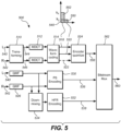
- Figure 5 shows by way of example a generalized block diagram of an encoding system 500 in accordance with an embodiment.
- the waveform-coding stage 514 is configured to waveform-code the first transformed signal 544 into a waveform-code signal 552 of the first waveform-coded signal 518.
- the waveform-coding stage 514 may be configured to set the second waveform-coded signal 520 to zero above the first cross-over frequency k y or to not encode theses frequencies at all
- the waveform-coding stage 514 is configured to waveform-code the first transformed signal 544 into a waveform-coded signal 552 of the first waveform-coded signal 518.
- different decisions can be made for different subsets of the waveform-coded signal 548, 550.
- the coding can either be Left/Right coding, Mid/Side coding, i.e. coding the sum and difference, or dmx/comp/a coding.
- An exemplary first cross-over frequency k y is 1.1 kHz, but this frequency may be varied depending on the bit transmission rate of the stereo audio system or depending on the characteristics of the audio to be encoded.
- At least two signals 518, 520 are thus outputted from the waveform-coding stage 514.
- this parameter is also outputted as a signal 522.
- each subset does not have to be coded with use of the same value of the weighting parameter a. In this case, several weighting parameters are outputted as the signal 522.
- the parametric stereo parameters 536 are reflecting the characteristics of the signal being parametric stereo encoded. They are thus frequency selective, i.e. each parameter of the parameters 536 may correspond to a subset of the frequencies of the left or the right input signal 540, 542.
- the PS encoding stage 530 calculates the parametric stereo parameters 536 and quantizes these either in a uniform or a non-uniform fashion.
- the parameters are as mentioned above calculated frequency selective, where the entire frequency range of the input signals 540, 542 is divided into e.g. 15 parameter bands. These may be spaced according to a model of the frequency resolution of the human auditory system, e.g. a bark scale.
- the encoder 500 further comprises a bitstream generating stage, i.e. bitstream multiplexer, 524.
- the bitstream generating stage is configured to receive the encoded and quantized signal 544, and the two parameters signals 536, 538. These are converted into a bitstream 560 by the bitstream generating stage 562, to further be distributed in the stereo audio system.
- the systems and methods disclosed hereinabove may be implemented as software, firmware, hardware or a combination thereof.
- the division of tasks between functional units referred to in the above description does not necessarily correspond to the division into physical units; to the contrary, one physical component may have multiple functionalities, and one task may be carried out by several physical components in cooperation.
- Certain components or all components may be implemented as software executed by a digital signal processor or microprocessor, or be implemented as hardware or as an application-specific integrated circuit.
- Such software may be distributed on computer readable media, which may comprise computer storage media (or non-transitory media) and communication media (or transitory media).
- Computer storage media includes both volatile and nonvolatile, removable and non-removable media implemented in any method or technology for storage of information such as computer readable instructions, data structures, program modules or other data.
- Computer storage media includes, but is not limited to, RAM, ROM, EEPROM, flash memory or other memory technology, CD-ROM, digital versatile disks (DVD) or other optical disk storage, magnetic cassettes, magnetic tape, magnetic disk storage or other magnetic storage devices, or any other medium which can be used to store the desired information and which can be accessed by a computer.
- communication media typically embodies computer readable instructions, data structures, program modules or other data in a modulated data signal such as a carrier wave or other transport mechanism and includes any information delivery media.
- EEEs enumerated example embodiments
Landscapes
- Engineering & Computer Science (AREA)
- Physics & Mathematics (AREA)
- Acoustics & Sound (AREA)
- Multimedia (AREA)
- Signal Processing (AREA)
- Computational Linguistics (AREA)
- Audiology, Speech & Language Pathology (AREA)
- Human Computer Interaction (AREA)
- Health & Medical Sciences (AREA)
- Spectroscopy & Molecular Physics (AREA)
- Mathematical Physics (AREA)
- Stereophonic System (AREA)
- Compression, Expansion, Code Conversion, And Decoders (AREA)
Abstract
Description
- This application is a European divisional application of
European patent application no. 19161888.3 - The disclosure herein generally relates to stereo audio coding. In particular it relates to a decoder and an encoder for hybrid coding comprising a downmix and discrete stereo coding.
- In conventional stereo audio coding, possible coding schemes include parametric stereo coding techniques which are used in low bitrate applications. At intermediate rates, Left/Right (L/R) or Mid/Side (M/S) waveform stereo coding is often used. The existing distribution formats and the associated coding techniques may be improved from the point of view of their bandwidth efficiency, especially in applications with a bitrate in between the low bitrate and the intermediate bitrate.
- An attempt to improve the efficiency of the audio distribution in a stereo audio system is made in the Unified Speech and Audio Coding (USAC) standard. The USAC standard introduces a low bandwidth waveform-coding based stereo coding in combination with parametric stereo coding techniques. However, the solution proposed by USAC uses the parametric stereo parameters to guide the stereo coding in the modified discrete cosine transform (MDCT) domain in order to do something more efficient than plain M/S or L/R coding. The drawback with the solution is that it may be difficult to get the best out of the low bandwidth waveform based stereo coding in the MDCT domain based on parametric stereo parameters extracted and calculated in a Quadrature Mirror Filters (QMF) domain.
- In view of the above, further improvement may be needed to solve or at least reduce one or several of the drawbacks discussed above.
- Example embodiments will now be described with reference to the accompanying drawings, on which:
-
figure 1 is a generalized block diagram of a decoding system in accordance with an example embodiment; -
figure 2 illustrates a first part of the decoding system infig 1 ; -
figure 3 illustrates a second part of the decoding system infig 1 ; -
figure 4 illustrates a third part of the decoding system infig 1 ; -
figure 5 is a generalized block diagram of an encoding system in accordance with a first example embodiment; -
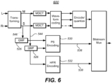
figure 6 is a generalized block diagram of an encoding system in accordance with a second example embodiment; - All the figures are schematic and generally only show parts which are necessary in order to elucidate the disclosure, whereas other parts may be omitted or merely suggested. Unless otherwise indicated, like reference numerals refer to like parts in different figures.
- As used herein, left-right coding or encoding means that the left (L) and right (R) stereo signals are coded without performing any transformation between the signals.
- As used herein, sum-and difference coding or encoding means that the sum M of the left and right stereo signals are coded as one signal (sum) and the difference S between the left and right stereo signal are coded as one signal (difference). The sum-and-difference coding may also be called mid-side coding. The relation between the left-right form and the sum-difference form is thus M=L+R and S=L-R. It may be noted that different normalizations or scaling are possible when transforming left and right stereo signals into the sum-and difference form and vice versa, as long as the transforming in both direction matches. In this disclosure, M=L+R and S=L-R is primarily used, but a system using a different scaling, e.g. M=(L+R)/2 and S=(L-R)/2 works equally well.
- As used herein, downmix-complementary (dmx/comp) coding or encoding means subjecting the left and right stereo signal to a matrix multiplication depending on a weighting parameter a prior to coding. The dmx/comp coding may thus also be called dmx/comp/a coding. The relation between the downmix-complementary form, the left-right form, and the sum-difference form is typically dmx = L+R = M, and comp = (1-a)L - (1+a)R = -aM+S. Notably, the downmix signal in the downmix-complementary representation is thus equivalent to the sum signal M of the sum-and-difference representation.
- As used herein, an audio signal may be a pure audio signal, an audio part of an audiovisual signal or multimedia signal or any of these in combination with metadata.
- According to a first aspect, example embodiments propose methods, devices and computer program products, for decoding a stereo channel audio signal based on an input signal. The proposed methods, devices and computer program products may generally have the same features and advantages.
- According to example embodiments, a decoder for decoding two audio signals is provided. The decoder comprises a receiving stage configured to receive a first signal and a second signal corresponding to a time frame of the two audio signals, wherein the first signal comprises a first waveform-coded signal comprising spectral data corresponding to frequencies up to a first cross-over frequency and a waveform-coded downmix signal comprising spectral data corresponding to frequencies above the first cross-over frequency, and wherein the second signal comprises a second waveform-coded signal comprising spectral data corresponding to frequencies up to the first cross-over frequency;
The decoder further comprises a mixing stage downstream of the receiving stage. The mixing stage is configured to check whether the first and the second signal waveform-coded signal are in a sum-and-difference form for all frequencies up to the first cross-over frequency, and if not, to transform the first and the second waveform-coded signal into a sum-and-difference form such that the first signal is a combination of a waveform-coded sum-signal comprising spectral data corresponding to frequencies up to the first cross-over frequency and the waveform-coded downmix signal comprising spectral data corresponding to frequencies above the first cross-over frequency, and the second signal comprises a waveform-coded difference-signal comprising spectral data corresponding to frequencies up to the first cross-over frequency. - The decoder further comprises an upmixing stage downstream of the mixing stage configured to upmix the first and the second signal so as to generate a left and a right channel of a stereo signal, wherein for frequencies below the first cross-over frequency the upmixing stage is configured to perform an inverse sum-and-difference transformation of the first and the second signal, and for frequencies above the first cross-over frequency the upmixing stage is configured to perform parametric upmixing of the downmix signal of the first signal.
- An advantage of having the lower frequencies purely waveform-coded, i.e. a discrete representation of the stereo audio signal, may be that the human ear is more sensitive to the part of the audio having low frequencies. By coding this part with a better quality, the overall impression of the decoded audio may increase.
- An advantage of having a parametric stereo coded part of the first signal, i.e. the waveform-coded downmix signal, and the mentioned discrete representation of the stereo audio signal is that this may improve the quality of the decoded audio signal for certain bit rates compared to using a conventional parametric stereo approach. At bitrates around 32-40 kilobits per second (kbps), the parametric stereo model may saturate, i.e. the quality of the decoded audio signal is limited by the shortcomings of the parametric model and not by lack of bits for coding. Consequently, for bitrates from around 32 kbps, it may be more beneficial to use bits on waveform-coding lower frequencies. At the same time, the hybrid approach of using both the parametric stereo coded part of the first signal and the discrete representation of the distributed stereo audio signal is that this may improve the quality of the decoded audio for certain bitrates, for example below 48 kbps, compared to using an approach where all bits are used on waveform-coding lower frequencies and using spectral band replication (SBR) for the remaining frequencies.
- The decoder is thus advantageously used for decoding a two channel stereo audio signal.
- According to another embodiment, the transforming of the first and the second waveform-coded signal into a sum-and-difference form in the mixing stage is performed in an overlapping windowed transform domain. The overlapping windowed transform domain may for example be a Modified Discrete Cosine Transform (MDCT) domain. This may be advantageous since the transformation of other available audio distributions formats, such as a left/right form or a dmx/comp-form, into the sum-and-difference form is easy to achieve in the MDCT domain. Consequently, the signals may be encoded using different formats for at least a subset of the frequencies below the first cross-over frequency depending on the characteristics of the signal being encoded. This may allow for an improved coding quality and coding efficiency.
- According to yet another embodiment, the upmixing of the first and the second signal in the upmixing stage is performed in a Quadrature Mirror Filters, QMF, domain. The upmixing is performed so as to generate a left and a right stereo signal.
- According to another embodiment, the waveform-coded downmix signal comprises spectral data corresponding to frequencies between the first cross-over frequency and a second cross-over frequency. High frequency reconstruction (HFR) parameters are received by the decoder, for example at the receiving stage and then sent to a high frequency reconstruction stage for extending the downmix signal of the first signal to a frequency range above the second cross-over frequency by performing high frequency reconstruction using the high frequency reconstruction parameters. The high frequency reconstruction may for example comprise performing spectral band replication, SBR.
- An advantage of having a waveform-coded downmix signal that only comprises spectral data corresponding to frequencies between the first cross-over frequency and a second cross-over frequency is that the required bit transmission rate for the stereo system may be decreased. Alternatively, the bits saved by having a band pass filtered downmix signal are used on waveform-coding lower frequencies, for example the quantization for those frequencies may be finer or the first cross-over frequency may be increased.
- Since, as mentioned above, the human ear is more sensitive to the part of the audio signal having low frequencies, high frequencies, such as the part of the audio signal having frequencies above the second cross-over frequency, may be recreated by high frequency reconstruction without reducing the perceived audio quality of the decoded audio signal.
- According to a further embodiment the downmix signal of the first signal is extended to a frequency range above the second cross-over frequency prior to the upmixing of the first and the second signal is performed. This may be advantageous since the upmixing stage will have and input sum-signal with spectral data corresponding to all frequencies.
- According to a further embodiment the downmix signal of the first signal is extended to a frequency range above the second cross-over frequency after transforming the first and the second waveform-coded signal into a sum-and-difference form. This may be advantageous since given that the downmix signal corresponds to the sum-signal in the sum-and-difference representation, the high frequency reconstruction stage will have an input signal with spectral data corresponding to frequencies up to the second cross-over frequency represented in the same form, i.e. in the sum-form.
- According to another embodiment, the upmixing in the upmixing stage is done with use of upmix parameters. The upmix parameters are received by the decoder, for example at the receiving stage and sent to the upmixing stage. A decorrelated version of the downmix signal is generated and the downmix signal and the decorrelated version of the downmix signal are subjected to a matrix operation. The parameters of the matrix operation are given by the upmix parameters.
- According to a further embodiment, the first and the second waveform coded signal, received at the receiving stage, are waveform-coded in a left-right form, a sum-difference form and/or a downmix-complementary form wherein the complementary signal depends on a weighting parameter a being signal adaptive. The waveform-coded signals may thus be coded on different forms depending on the characteristics of the signals and still be decodable by the decoder. This may allow for an improved coding quality and thus an improved quality of the decoded audio stereo signal given a certain bitrate of the system. In a further embodiment, the weighting parameter a is real-valued. This may simplify the decoder since no extra stage approximating the imaginary part of the signal is needed. A further advantage is that the computational complexity of the decoder may be decreased which may also lead to a decreased decoding delay/latency of the decoder.
- According to yet another embodiment, the first and the second waveform coded signal, received at the receiving stage, are waveform-coded in a sum-difference form. This means that the first and the second signal can be coded using overlapping windowed transforms with independent windowing for the first and the second signal, respectively, and still be decodable by the decoder. This may allow for an improved coding quality and thus an improved quality of the decoded audio stereo signal given a certain bitrate of the system. For example, if a transient is detected in the sum signal but not in the difference signal, the waveform coder may code the sum signal with shorter windows while for the difference signal, the longer default windows may be kept. This may provide higher coding efficiency compared to if the side signal also was coded with the shorter window sequence.
- According to a second aspect, example embodiments propose methods, devices and computer program products for encoding a stereo channel audio signal based on an input signal.
- The proposed methods, devices and computer program products may generally have the same features and advantages.
- Advantages regarding features and setups as presented in the overview of the decoder above may generally be valid for the corresponding features and setups for the encoder.
- According to the example embodiments, an encoder for encoding two audio signals is provided. The encoder comprises a receiving stage configured to receive a first signal and a second signal, corresponding to a time frame of the two signals, to be encoded.
- The encoder further comprises a transforming stage configured to receive the first and the second signal from the receiving stage and to transform them into a first transformed signal being a sum signal and a second transformed signal being a difference signal.
- The encoder further comprises a waveform-coding stage configured to receive the first and the second transformed signal from the transforming stage and to waveform-code them into a first and a second waveform-coded signal, respectively, wherein for frequencies above a first cross-over frequency the waveform-coding stage is configured to waveform-code the first transformed signal, and wherein for frequencies up to the first cross-over frequency the waveform-coding stage is configured to waveform-code the first and the second transformed signal.
- The encoder further comprises a parametric stereo encoding stage configured to receive the first and the second signal from the receiving stage and to subject the first and the second signal to parametric stereo encoding in order to extract parametric stereo parameters enabling reconstruction of spectral data of the first and the second signal for frequencies above the first cross-over frequency;
- The encoder further comprises a bitstream generating stage configured to receive the first and the second waveform-coded signal from the waveform-coding stage and the parametric stereo parameters from the parametric stereo encoding stage, and to generate a bit-stream comprising the first and the second waveform-coded signal and the parametric stereo parameters.
- According to another embodiment, the transforming of the first and the second signal in the transforming stage is performed in the time domain.
- According to another embodiment, for at least a subset of the frequencies below the first cross-over frequency, the encoder may transform the first and the second waveform-coded signal into a left/right form by performing an inverse sum-and difference transformation.
- According to another embodiment, for at least a subset of the frequencies below the first cross-over frequency, the encoder may transform the first and the second waveform-coded signal into a downmix/complementary form by performing a matrix operation on the first and the second waveform-coded signals, the matrix operation depending on a weighting parameter a. The weighting parameter a may then be included in the bitstream in bitstream generating stage.
- According to yet another embodiment, for frequencies above the first cross-over frequency, waveform-coding the first and the second transformed signal in the transforming stage comprises waveform-coding the first transformed signal for frequencies between the first cross-over frequency and a second cross-over frequency and setting the first waveform-coded signal to zero above the second cross-over frequency. A downmix signal of the first signal and the second signal may then be subjected to a high frequency reconstruction encoding in a high frequency reconstruction stage in order to generate high frequency reconstruction parameters enabling high frequency reconstruction of the downmix signal. The high frequency reconstruction parameters may then be included in the bitstream in the bitstream generating stage.
- According to a further embodiment, downmix signal is calculated based on the first and the second signal.
- According to another embodiment, subjecting the first and the second signal to parametric stereo encoding in the parametric stereo encoding stage is performed by first transforming the first and the second signal into a first transformed signal being a sum signal and a second transformed signal being a difference signal, and then subjecting the first and the second transformed signal to parametric stereo encoding, wherein the downmix signal being subject to high frequency reconstruction encoding is the first transformed signal.
-
Figure 1 is a generalized block diagram of adecoding system 100 comprising threeconceptual parts fig 2-4 below. In firstconceptual part 200, a bit stream is received and decoded into a first and a second signal. The first signal comprises both a first waveform-coded signal comprising spectral data corresponding to frequencies up to a first cross-over frequency and a waveform-coded downmix signal comprising spectral data corresponding to frequencies above the first cross-over frequency. The second signal only comprises a second waveform-coded signal comprising spectral data corresponding to frequencies up to the first cross-over frequency. - In the second
conceptual part 300, in case the waveform-coded parts of the first and second signal is not in a sum-and-difference form, e.g. in an M/S form, the waveform-coded parts of the first and second signal are transformed to the sum-and-difference form. After that, the first and the second signal are transformed into the time domain and then into the Quadrature Mirror Filters, QMF, domain. In the thirdconceptual part 400, the first signal is high frequency reconstructed (HFR). Both the first and the second signal is then upmixed to create a left and a right stereo signal output having spectral coefficients corresponding to the entire frequency band of the encoded signal being decoded by thedecoding system 100. -
Figure 2 illustrates the firstconceptual part 200 of thedecoding system 100 infigure 1 . Thedecoding system 100 comprises a receiving stage 212. In the receiving stage 212, abit stream frame 202 is decoded and dequantizing into a first signal 204a and a second signal 204b. Thebit stream frame 202 corresponds to a time frame of the two audio signals being decoded. The first signal 204a comprises a first waveform-codedsignal 208 comprising spectral data corresponding to frequencies up to a first cross-over frequency ky and a waveform-codeddownmix signal 206 comprising spectral data corresponding to frequencies above the first cross-over frequency ky. By way of example, the first cross-over frequency ky is 1.1 kHz. - According to some embodiments, the waveform-coded
downmix signal 206 comprises spectral data corresponding to frequencies between the first cross-over frequency ky and a second cross-over frequency kx. By way of example, the second cross-over frequency kx lies within the range of is 5.6-8 kHz. - The received first and second wave-form coded
signals downmix signal 206 corresponds to a downmix suitable for parametric stereo which, according to the above, corresponds to a sum form. However, the signal 204b has no content above the first cross-over frequency ky. Each of thesignals -
Figure 3 illustrates the secondconceptual part 300 of thedecoding system 100 infigure 1 . Thedecoding system 100 comprises a mixingstage 302. The design of thedecoding system 100 requires that the input to the high frequency reconstruction stage, which will be described in greater detail below, needs to be in a sum-format. Consequently, the mixing stage is configured to check whether the first and the second signal waveform-codedsignal signal stage 302 will transform the entire waveform-codedsignal stage 302 is in a downmix-complementary form, the weighting parameter a is required as an input to the mixingstage 302. It may be noted that the input signals 208, 210 may comprise several subset of frequencies coded in a downmix-complementary form and that in that case each subset does not have to be coded with use of the same value of the weighting parameter a. In this case, several weighting parameters a are required as an input to the mixingstage 302. - As mentioned above, the mixing
stage 302 always output a sum-and-difference representation of the input signals 204a-b. To be able to transform signals represented in the MDCT domain into the sum-and-difference representation, the windowing of the MDCT coded signals need to be the same. This implies that, in case the first and the second signal waveform-codedsignal - Consequently, in case the first and the second signal waveform-coded
signal - After the
mixing stage 302, the sum-and-difference signal is transformed into the time domain by applying an inverse modified discrete cosine transform (MDCT-1) 312. - The two signals 304a-b are then analyzed with two
QMF banks 314. Since thedownmix signal 306 does not comprise the lower frequencies, there is no need of analyzing the signal with a Nyquist filterbank to increase frequency resolution. This may be compared to systems where the downmix signal comprises low frequencies, e.g. conventional parametric stereo decoding such as MPEG-4 parametric stereo. In those systems, the downmix signal needs to be analyzed with the Nyquist filterbank in order to increases the frequency resolution beyond what is achieved by a QMF bank and thus better match the frequency selectivity of the human auditory system, as e.g. represented by the Bark frequency scale. - The
output signal 304 from theQMF banks 314 comprises a first signal 304a which is a combination of a waveform-coded sum-signal 308 comprising spectral data corresponding to frequencies up to the first cross-over frequency ky and the waveform-codeddownmix signal 306 comprising spectral data corresponding to frequencies between the first cross-over frequency ky and the second cross-over frequency kx. Theoutput signal 304 further comprises a second signal 304b which comprises a waveform-coded difference-signal 310 comprising spectral data corresponding to frequencies up to the first cross-over frequency ky. The signal 304b has no content above the first cross-over frequency ky. - As will be described later on, a high frequency reconstruction stage 416 (shown in conjunction with
fig. 4 ) uses the lower frequencies, i.e. the first waveform-codedsignal 308 and the waveform-codeddownmix signal 306 from theoutput signal 304, for reconstructing the frequencies above the second cross-over frequency kx. It is advantageous that the signal on which the highfrequency reconstruction stage 416 operates on is a signal of similar type across the lower frequencies. From this perspective it is advantageous to have the mixingstage 302 to always output a sum-and-difference representation of the first and the second signal waveform-codedsignal signal 308 and the waveform-codeddownmix signal 306 of the outputted first signal 304a are of similar character. -
Figure 4 illustrates the thirdconceptual part 400 of thedecoding system 100 infigure 1 . The high frequency reconstruction (HRF)stage 416 is extending thedownmix signal 306 of the first signal input signal 304a to a frequency range above the second cross-over frequency kx by performing high frequency reconstruction. Depending on the configuration of theHFR stage 416, the input to theHFR stage 416 is the entire signal 304a or the just thedownmix signal 306. The high frequency reconstruction is done by using high frequency reconstruction parameters which may be received by highfrequency reconstruction stage 416 in any suitable way. According to an embodiment, the performed high frequency reconstruction comprises performing spectral band replication, SBR. - The output from the high
frequency reconstruction stage 314 is asignal 404 comprising thedownmix signal 406 with theSBR extension 412 applied. The high frequencyreconstructed signal 404 and the signal 304b is then fed into anupmixing stage 420 so as to generate a left L and a right R stereo signal 412a-b. For the spectral coefficients corresponding to frequencies below the first cross-over frequency ky the upmixing comprises performing an inverse sum-and-difference transformation of the first and thesecond signal downmix signal 406 and theSBR extension 412 is fed through adecorrelator 418. Thedownmix signal 406 and theSBR extension 412 and the decorrelated version of thedownmix signal 406 and theSBR extension 412 is then upmixed using parametric mixing parameters to reconstruct the left and theright cannels - It should be noted that in the above
exemplary embodiment 100 of the encoder, shown infigures 1-4 , high frequency reconstruction is needed since the first received signal 204a only comprises spectral data corresponding to frequencies up to the second cross-over frequency kx. In further embodiments, the first received signal comprises spectral data corresponding to all frequencies of the encoded signal. According to this embodiment, high frequency reconstruction is not needed. The person skilled in the art understands how to adapt theexemplary encoder 100 in this case. -
Figure 5 shows by way of example a generalized block diagram of anencoding system 500 in accordance with an embodiment. - In the encoding system, a first and
second signal signals signals stage 510. Thesignals difference format stage 510. - The encoding system further comprising a waveform-
coding stage 514 configured to receive the first and the second transformedsignal stage 510. The waveform-coding stage typically operates in a MDCT domain. For this reason, the transformed signals 544, 546 are subjected to a MDCT transform 512 prior to the waveform-coding stage 514. In the waveform-coding stage, the first and the second transformedsignal signal - For frequencies above a first cross-over frequency ky, the waveform-
coding stage 514 is configured to waveform-code the first transformedsignal 544 into a waveform-code signal 552 of the first waveform-codedsignal 518. The waveform-coding stage 514 may be configured to set the second waveform-codedsignal 520 to zero above the first cross-over frequency ky or to not encode theses frequencies at all For frequencies above the first cross-over frequency ky, the waveform-coding stage 514 is configured to waveform-code the first transformedsignal 544 into a waveform-codedsignal 552 of the first waveform-codedsignal 518.. - For frequencies below the first cross-over frequency ky, , a decision is made in the waveform-
coding stage 514 on what kind of stereo coding to use for the twosignals signal signals coding stage 514, the waveform-codedsignals signals - An exemplary first cross-over frequency ky is 1.1 kHz, but this frequency may be varied depending on the bit transmission rate of the stereo audio system or depending on the characteristics of the audio to be encoded.
- At least two
signals coding stage 514. In the case one or several subsets, or the entire frequency band, of the signals below the first cross over frequency ky are coded in a downmix/complementary form by performing a matrix operation, depending on the weighting parameter a, this parameter is also outputted as asignal 522. In the case of several subsets being encoded in a downmix/complementary form, each subset does not have to be coded with use of the same value of the weighting parameter a. In this case, several weighting parameters are outputted as thesignal 522. - These two or three
signals composite signal 558. - To be able to reconstruct the spectral data of the first and the
second signal parametric stereo parameters 536 needs to be extracted from thesignals encoder 500 comprises a parametric stereo (PS) encodingstage 530. ThePS encoding stage 530 typically operates in a QMF domain. Therefore, prior to being input to thePS encoding stage 530, the first andsecond signals QMF analysis stage 526. ThePS encoder stage 530 is adapted to only extractparametric stereo parameters 536 for frequencies above the first cross-over frequency ky. - It may be noted that the
parametric stereo parameters 536 are reflecting the characteristics of the signal being parametric stereo encoded. They are thus frequency selective, i.e. each parameter of theparameters 536 may correspond to a subset of the frequencies of the left or theright input signal 540, 542.ThePS encoding stage 530 calculates theparametric stereo parameters 536 and quantizes these either in a uniform or a non-uniform fashion. The parameters are as mentioned above calculated frequency selective, where the entire frequency range of the input signals 540, 542 is divided into e.g. 15 parameter bands. These may be spaced according to a model of the frequency resolution of the human auditory system, e.g. a bark scale. - In the exemplary embodiment of the
encoder 500 shown infigure 5 , the waveform-coding stage 514 is configured to waveform-code the first transformedsignal 544 for frequencies between the first cross-over frequency ky and a second cross-over frequency kx and setting the first waveform-codedsignal 518 to zero above the second cross-over frequency kx. This may be done to further reduce the required transmission rate of the audio system in which theencoder 500 is a part. To be able to reconstruct the signal above the second cross-over frequency kx, highfrequency reconstruction parameters 538 needs to be generated. According to this exemplary embodiment, this is done by downmixing the twosignals downmixing stage 534. The resulting downmix signal, which for example is equal to the sum of thesignals stage 532 in order to generate the highfrequency reconstruction parameters 538. Theparameters 538 may for example include a spectral envelope of the frequencies above the second cross-over frequency kx, noise addition information etc. as well known to the person skilled in the art. - An exemplary second cross-over frequency kx is 5.6-8 kHz, but this frequency may be varied depending on the bit transmission rate of the stereo audio system or depending on the characteristics of the audio to be encoded.
- The
encoder 500 further comprises a bitstream generating stage, i.e. bitstream multiplexer, 524. According to the exemplary embodiment of theencoder 500, the bitstream generating stage is configured to receive the encoded andquantized signal 544, and the twoparameters signals bitstream 560 by thebitstream generating stage 562, to further be distributed in the stereo audio system. - According to another embodiment, the waveform-
coding stage 514 is configured to waveform-code the first transformedsignal 544 for all frequencies above the first cross-over frequency ky. In this case, theHFR encoding stage 532 is not needed and consequently no highfrequency reconstruction parameters 538 are included in the bit-stream. -
Figure 6 shows by way of example a generalized block diagram of anencoder system 600 in accordance with another embodiment. This embodiment differs from the embodiment shown infigure 5 in that thesignals QMF analysis stage 526 are in a sum-and-difference format. Consequently, there is no need for aseparate downmixing stage 534 since thesum signal 544 is already in the form of a downmix signal. TheSBR encoding stage 532 thus only needs to operate on the sum-signal 544 to extract the highfrequency reconstruction parameters 538. ThePS encoder 530 is adapted to operate on both the sum-signal 544 and the difference-signal 546 to extract theparametric stereo parameters 536. - Further embodiments of the present disclosure will become apparent to a person skilled in the art after studying the description above. Even though the present description and drawings disclose embodiments and examples, the disclosure is not restricted to these specific examples. Numerous modifications and variations can be made without departing from the scope of the present disclosure, which is defined by the accompanying claims. Any reference signs appearing in the claims are not to be understood as limiting their scope.
- Additionally, variations to the disclosed embodiments can be understood and effected by the skilled person in practicing the disclosure, from a study of the drawings, the disclosure, and the appended claims. In the claims, the word "comprising" does not exclude other elements or steps, and the indefinite article "a" or "an" does not exclude a plurality. The mere fact that certain measures are recited in mutually different dependent claims does not indicate that a combination of these measured cannot be used to advantage.
- The systems and methods disclosed hereinabove may be implemented as software, firmware, hardware or a combination thereof. In a hardware implementation, the division of tasks between functional units referred to in the above description does not necessarily correspond to the division into physical units; to the contrary, one physical component may have multiple functionalities, and one task may be carried out by several physical components in cooperation. Certain components or all components may be implemented as software executed by a digital signal processor or microprocessor, or be implemented as hardware or as an application-specific integrated circuit. Such software may be distributed on computer readable media, which may comprise computer storage media (or non-transitory media) and communication media (or transitory media). As is well known to a person skilled in the art, the term computer storage media includes both volatile and nonvolatile, removable and non-removable media implemented in any method or technology for storage of information such as computer readable instructions, data structures, program modules or other data. Computer storage media includes, but is not limited to, RAM, ROM, EEPROM, flash memory or other memory technology, CD-ROM, digital versatile disks (DVD) or other optical disk storage, magnetic cassettes, magnetic tape, magnetic disk storage or other magnetic storage devices, or any other medium which can be used to store the desired information and which can be accessed by a computer. Further, it is well known to the skilled person that communication media typically embodies computer readable instructions, data structures, program modules or other data in a modulated data signal such as a carrier wave or other transport mechanism and includes any information delivery media.
- Various aspects of the present invention may be appreciated from the following enumerated example embodiments (EEEs):
- 1. A decoding method for decoding two audio signals, comprising the steps of:
- receiving a first signal and a second signal corresponding to a time frame of the two audio signals, wherein the first signal comprises a first waveform-coded signal comprising spectral data corresponding to frequencies up to a first cross-over frequency and a waveform-coded downmix signal comprising spectral data corresponding to frequencies above the first cross-over frequency, and wherein the second signal comprises a second waveform-coded signal comprising spectral data corresponding to frequencies up to the first cross-over frequency;
- if the first and the second waveform-coded signal are not in a sum-and-difference form for all frequencies up to the first cross-over frequency, transforming the first and the second waveform-coded signal into a sum-and-difference form such that the first signal is a combination of a waveform-coded sum-signal comprising spectral data corresponding to frequencies up to the first cross-over frequency and the waveform-coded downmix signal comprising spectral data corresponding to frequencies above the first cross-over frequency, and the second signal comprises a waveform-coded difference-signal comprising spectral data corresponding to frequencies up to the first cross-over frequency; and
- upmixing the first and the second signal so as to generate a left and a right channel of a stereo signal, wherein for frequencies below the first cross-over frequency the upmixing comprises performing an inverse sum-and-difference transformation of the first and the second signal, and for frequencies above the first cross-over frequency the upmixing comprises performing parametric upmixing of the downmix signal of the first signal.
- 2. The decoding method of EEE 1, wherein the step of transforming the first and the second waveform-coded signal into a sum-and-difference form is performed in an overlapping windowed transform domain.
- 3. The decoding method of EEE 2, wherein the overlapping windowed transform domain is a Modified Discrete Cosine Transform, MDCT, domain.
- 4. The decoding method of any of the preceding EEEs, wherein the step of upmixing the first and the second signal so as to generate a left and a right stereo signal is performed in a Quadrature Mirror Filters, QMF, domain.
- 5. The decoding method of any of the preceding EEEs, wherein the waveform-coded downmix signal comprises spectral data corresponding to frequencies between the first cross-over frequency and a second cross-over frequency, the method further comprising:
- receiving high frequency reconstruction parameters; and
- extending the downmix signal of the first signal to a frequency range above the second cross-over frequency by performing high frequency reconstruction using the high frequency reconstruction parameters.
- 6. The decoding method of EEE 5, wherein the step of extending the downmix signal of the first signal to a frequency range above the second cross-over frequency by performing high frequency reconstruction comprises performing spectral band replication, SBR.
- 7. The decoding method of any one of EEEs 5 or 6, wherein the step of extending the downmix signal of the first signal to a frequency range above the second cross-over frequency is performed prior to the step of upmixing the first and the second signal.
- 8. The decoding method of any one of EEEs 5-7, wherein the step of extending the downmix signal of the first signal to a frequency range above the second cross-over frequency is performed after the step of transforming the first and the second waveform-coded signal into a sum-and-difference form.
- 9. The decoding method of any of the preceding EEEs, wherein the step of parametric upmixing of the downmix signal of the first signal comprises:
- receiving upmix parameters;
- generating a decorrelated version of the downmix signal; and
- subjecting the downmix signal and the decorrelated version of the downmix signal to a matrix operation, wherein the parameters of the matrix operation are given by the upmix parameters.
- 10. The decoding method of any of the preceding EEEs, wherein the first and the second wave-form coded signal as received are waveform-coded in a left-right form, a sum-difference form and/or a downmix-complementary form wherein the complementary signal depends on a weighting parameter a being signal adaptive.
- 11. The decoding method of EEE 10, wherein the weighting parameter a is real-valued.
- 12. The decoding method of EEE 10, wherein the first and the second waveform-coded signal as received are waveform-coded in a sum-difference form, and wherein the first and the second signal are coded using overlapping windowed transforms with independent windowing for the first and the second signal, respectively.
- 13. A computer program product comprising a computer-readable medium with instructions for performing the method of any of the preceding EEEs.
- 14. A decoder for decoding two audio signals, comprising
- a receiving stage configured to receive a first signal and a second signal corresponding to a time frame of the two audio signals, wherein the first signal comprises a first waveform-coded signal comprising spectral data corresponding to frequencies up to a first cross-over frequency and a waveform-coded downmix signal comprising spectral data corresponding to frequencies above the first cross-over frequency, and wherein the second signal comprises a second waveform-coded signal comprising spectral data corresponding to frequencies up to the first cross-over frequency;
- a mixing stage downstream of the receiving stage being configured to check whether the first and the second signal waveform-coded signal are in a sum-and-difference form for all frequencies up to the first cross-over frequency, and if not, to transform the first and the second waveform-coded signal into a sum-and-difference form such that the first signal is a combination of a waveform-coded sum-signal comprising spectral data corresponding to frequencies up to the first cross-over frequency and the waveform-coded downmix signal comprising spectral data corresponding to frequencies above the first cross-over frequency, and the second signal comprises a waveform-coded difference-signal comprising spectral data corresponding to frequencies up to the first cross-over frequency; and
- 15. An encoding method for encoding two audio signals, comprising the steps of:
- receiving a first signal and a second signal, corresponding to a time frame of the two audio signals, to be encoded;
- transforming the first and the second signal into a first transformed signal being a sum signal and a second transformed signal being a difference signal;
- waveform-coding the first and the second transformed signal into a first and a second waveform-coded signal, respectively, wherein for frequencies above a first cross-over frequency the waveform-coding comprises waveform-coding the first transformed signal, and wherein for frequencies up to the first cross-over frequency the waveform-coding comprises waveform-coding the first and the second transformed signal;
- subjecting the first and the second signal to parametric stereo encoding in order to extract parametric stereo parameters enabling reconstruction of spectral data of the first and the second signal for frequencies above the first cross-over frequency;
- generating a bit-stream comprising the first and the second waveform-coded signal and the parametric stereo parameters.
- 16. The encoding method of EEE 15, wherein the step of transforming the first and the second signal is performed in the time domain.
- 17. The encoding method of any one of EEEs 15-16, further comprising: for at least a subset of the frequencies below the first cross-over frequency, transforming the first and the second waveform-coded signal into a left/right form by performing an inverse sum-and difference transformation.
- 18. The encoding method of any one of EEEs 15-17, further comprising:
- for at least a subset of the frequencies below the first cross-over frequency, transforming the first and the second waveform-coded signal into a downmix/complementary form by performing a matrix operation on the first and the second waveform-coded signals, the matrix operation depending on a weighting parameter a;
- and including the weighting parameter a in the bitstream.
- 19. The encoding method of any one of EEEs 15-18, wherein
for frequencies above the first cross-over frequency the step of waveform-coding the first and the second transformed signal comprises waveform-coding the first transformed signal for frequencies between the first cross-over frequency and a second cross-over frequency and setting the first waveform-coded signal to zero above the second cross-over frequency; the method further comprising:- subjecting a downmix signal of the first signal and the second signal to high frequency reconstruction encoding in order to generate high frequency reconstruction parameters enabling high frequency reconstruction of the downmix signal; and
- including the high frequency reconstruction parameters in the bitstream.
- 20. The encoding method of EEE 19, further comprising calculating the downmix signal based on the first and the second signal.
- 21. The encoding method of EEE 19, wherein the step of subjecting the first and the second signal to parametric stereo encoding is performed by first performing the step of transforming the first and the second signal into a first transformed signal being a sum signal and a second transformed signal being a difference signal, and then subjecting the first and the second transformed signal to parametric stereo encoding, wherein the downmix signal being subject to high frequency reconstruction encoding is the first transformed signal.
- 22. A computer program product comprising a computer-readable medium with instructions for performing the method of any of the EEEs 15-21.
- 23. An encoder for encoding two audio signals, comprising:
- a receiving stage configured to receive a first signal and a second signal, corresponding to a time frame of the two audio signals, to be encoded;
- a transforming stage configured to receive the first and the second signal from the receiving stage and to transform them into a first transformed signal being a sum signal and a second transformed signal being a difference signal;
- a waveform-coding stage configured to receive the first and the second transformed signal from the transforming stage and to waveform-code them into a first and a second waveform-coded signal, respectively, wherein for frequencies above a first cross-over frequency the waveform-coding stage is configured to waveform-code the first transformed signal, and wherein for frequencies up to the first cross-over frequency the waveform-coding stage is configured to waveform-code the first and the second transformed signal;
- a parametric stereo encoding stage configured to receive the first and the second signal from the receiving stage and to subject the first and the second signal to parametric stereo encoding in order to extract parametric stereo parameters enabling reconstruction of spectral data of the first and the second signal for frequencies above the first cross-over frequency;
- a bitstream generating stage configured to receive the first and the second waveform-coded signal from the waveform-coding stage and the parametric stereo parameters from the parametric stereo encoding stage, and to generate a bit-stream comprising the first and the second waveform-coded signal and the parametric stereo parameters.
Claims (15)
- A decoding system (100) comprising:a high frequency reconstruction stage (416) configured to:- receive a waveform-coded audio sum-signal (308) comprising spectral data corresponding to frequencies only up to a first cross-over frequency (ky);- receive a waveform-coded audio downmix signal (306) comprising spectral data corresponding to frequencies between the first cross-over frequency (ky), and a second cross-over frequency (kx);- receive high frequency reconstruction parameters;- perform high frequency reconstruction using the high frequency reconstruction parameters to generate a high frequency reconstructed signal (412) comprising spectral content only above the second cross-over frequency (kx), wherein the waveform-coded audio downmix signal (306) is used as input for performing said high frequency reconstruction;- combine the waveform-coded audio sum-signal (308), the waveform-coded audio downmix signal (306) and the high frequency reconstructed signal (412) to determine a combined signal (404);the decoding system (100) further comprising an upmixing stage (420) configured to:- receive the combined signal (404) and a waveform-coded audio difference-signal (310) comprising spectral data corresponding to frequencies only up to the first cross-over frequency (ky);- upmixing the combined signal (404) and the waveform-coded audio difference-signal (310) to generate a left and a right audio stereo signal (412a, 412b); and- outputing the left and right audio stereo signal (412a, 412b).
- The decoding system (100) of claim 1, further comprising a decorrelator (418), configured to:- receive the waveform-coded audio downmix signal (306) and the high frequency reconstructed signal (412); and- generate a decorrelated waveform-coded audio downmix signal and a decorrelated high frequency reconstructed signal.
- The decoding system (100) of claim 1 or 2, wherein the combining the waveform-coded audio sum-signal (308), the waveform-coded audio downmix signal (306) and the high frequency reconstructed signal (412) comprises adding the waveform-coded audio downmix signal (306) with the high frequency reconstructed signal (412) and the waveform-coded audio sum-signal (308).
- The decoding system (100) of any one of claims 1 - 3, wherein the high frequency reconstruction parameters comprise a spectral envelope or noise addition information.
- The decoding system (100) of any of claims 1 - 4, wherein performing high frequency reconstructing comprises performing spectral band replication, SBR.
- The decoding system (100) of any of claims 1 - 5, configured to receive an encoded audio bitstream that includes said waveform-coded audio sum-signal (308) and said waveform-coded audio downmix signal (308).
- The decoding system (100) of claim 6, wherein the first cross-over frequency (ky) depends on a bit transmission rate of the encoded audio bitstream.
- A method comprising:- receiving a waveform-coded audio sum-signal (308) comprising spectral data corresponding to frequencies only up to a first cross-over frequency (ky);- receiving a waveform-coded audio downmix signal (306) comprising spectral data corresponding to frequencies between the first cross-over frequency (ky) and a second cross-over frequency (kx);- receiving high frequency reconstruction parameters;- performing high frequency reconstruction using the high frequency reconstruction parameters to generate a high frequency reconstructed signal (412) comprising spectral content only above the second cross-over frequency (kx), wherein only the waveform-coded audio downmix signal (306) is used as input for performing said high frequency reconstruction;- combining the waveform-coded audio sum-signal (308), the waveform-coded audio downmix signal (306), and the high frequency reconstructed signal (412) to determine a combined signal (404);- receiving a waveform-coded audio difference-signal (310) comprising spectral data corresponding to frequencies only up to the first cross-over frequency (ky);- upmixing the combined signal (404) and the waveform-coded audio difference-signal (310) to generate a left and a right audio stereo signal (412a, 412b); and- outputting the left and right audio stereo signal (412a, 412b).
- The method of claim 8, further comprising:- decorrelating the waveform-coded audio downmix signal (306) and the high frequency reconstructed signal (412) prior to upmixing.
- The method of claim 8 or 9, wherein said combining comprises adding the waveform-coded audio downmix signal (306) with the high frequency reconstructed signal (412) and the waveform-coded audio sum-signal (308).
- The method of any one of claims 8 - 10, wherein the high frequency reconstruction parameters comprise a spectral envelope of the frequencies above the second cross-over frequency (kx), or noise addition information.
- The method of any of claims 8 - 11, wherein performing high frequency reconstructing comprises performing spectral band replication, SBR.
- The method of any of the claims 8 - 12, wherein said waveform-coded sum-signal (308) and said waveform-coded audio downmix signal (306) are received as part of an encoded audio bitstream.
- The method of claim 13, wherein the first cross-over frequency (ky) depends on a bit transmission rate of the encoded audio bitstream.
- A computer program product having instructions which, when executed on a computing device or system, cause said computing device or system to perform the method according to any of claims 8 - 14.
Priority Applications (1)
| Application Number | Priority Date | Filing Date | Title |
|---|---|---|---|
| EP26160589.3A EP4765112A3 (en) | 2013-04-05 | 2014-04-04 | Stereo audio encoder and decoder |
Applications Claiming Priority (4)
| Application Number | Priority Date | Filing Date | Title |
|---|---|---|---|
| US201361808684P | 2013-04-05 | 2013-04-05 | |
| EP19161888.3A EP3528249A1 (en) | 2013-04-05 | 2014-04-04 | Stereo audio encoder and decoder |
| PCT/EP2014/056854 WO2014161993A1 (en) | 2013-04-05 | 2014-04-04 | Stereo audio encoder and decoder |
| EP14716280.4A EP2981960B1 (en) | 2013-04-05 | 2014-04-04 | Stereo audio encoder and decoder |
Related Parent Applications (2)
| Application Number | Title | Priority Date | Filing Date |
|---|---|---|---|
| EP14716280.4A Division EP2981960B1 (en) | 2013-04-05 | 2014-04-04 | Stereo audio encoder and decoder |
| EP19161888.3A Division EP3528249A1 (en) | 2013-04-05 | 2014-04-04 | Stereo audio encoder and decoder |
Related Child Applications (1)
| Application Number | Title | Priority Date | Filing Date |
|---|---|---|---|
| EP26160589.3A Division EP4765112A3 (en) | 2013-04-05 | 2014-04-04 | Stereo audio encoder and decoder |
Publications (3)
| Publication Number | Publication Date |
|---|---|
| EP4300488A2 true EP4300488A2 (en) | 2024-01-03 |
| EP4300488A3 EP4300488A3 (en) | 2024-02-28 |
| EP4300488B1 EP4300488B1 (en) | 2026-03-04 |
Family
ID=50473291
Family Applications (4)
| Application Number | Title | Priority Date | Filing Date |
|---|---|---|---|
| EP19161888.3A Ceased EP3528249A1 (en) | 2013-04-05 | 2014-04-04 | Stereo audio encoder and decoder |
| EP14716280.4A Active EP2981960B1 (en) | 2013-04-05 | 2014-04-04 | Stereo audio encoder and decoder |
| EP26160589.3A Pending EP4765112A3 (en) | 2013-04-05 | 2014-04-04 | Stereo audio encoder and decoder |
| EP23197482.5A Active EP4300488B1 (en) | 2013-04-05 | 2014-04-04 | Stereo audio encoder and decoder |
Family Applications Before (3)
| Application Number | Title | Priority Date | Filing Date |
|---|---|---|---|
| EP19161888.3A Ceased EP3528249A1 (en) | 2013-04-05 | 2014-04-04 | Stereo audio encoder and decoder |
| EP14716280.4A Active EP2981960B1 (en) | 2013-04-05 | 2014-04-04 | Stereo audio encoder and decoder |
| EP26160589.3A Pending EP4765112A3 (en) | 2013-04-05 | 2014-04-04 | Stereo audio encoder and decoder |
Country Status (8)
| Country | Link |
|---|---|
| US (6) | US9570083B2 (en) |
| EP (4) | EP3528249A1 (en) |
| JP (1) | JP6019266B2 (en) |
| KR (4) | KR20230020553A (en) |
| CN (6) | CN116741186A (en) |
| BR (4) | BR122017006701B1 (en) |
| RU (3) | RU2645271C2 (en) |
| WO (1) | WO2014161993A1 (en) |
Families Citing this family (24)
| Publication number | Priority date | Publication date | Assignee | Title |
|---|---|---|---|---|
| TWI546799B (en) | 2013-04-05 | 2016-08-21 | 杜比國際公司 | Audio encoder and decoder |
| ES2643789T3 (en) | 2013-05-24 | 2017-11-24 | Dolby International Ab | Efficient coding of audio scenes comprising audio objects |
| EP2973551B1 (en) | 2013-05-24 | 2017-05-03 | Dolby International AB | Reconstruction of audio scenes from a downmix |
| CA3017077C (en) | 2013-05-24 | 2021-08-17 | Dolby International Ab | Coding of audio scenes |
| WO2014187990A1 (en) | 2013-05-24 | 2014-11-27 | Dolby International Ab | Efficient coding of audio scenes comprising audio objects |
| RU2639952C2 (en) * | 2013-08-28 | 2017-12-25 | Долби Лабораторис Лайсэнзин Корпорейшн | Hybrid speech amplification with signal form coding and parametric coding |
| EP3561809B1 (en) | 2013-09-12 | 2023-11-22 | Dolby International AB | Method for decoding and decoder. |
| WO2015036350A1 (en) * | 2013-09-12 | 2015-03-19 | Dolby International Ab | Audio decoding system and audio encoding system |
| EP2922056A1 (en) | 2014-03-19 | 2015-09-23 | Fraunhofer-Gesellschaft zur Förderung der angewandten Forschung e.V. | Apparatus, method and corresponding computer program for generating an error concealment signal using power compensation |
| EP2922055A1 (en) * | 2014-03-19 | 2015-09-23 | Fraunhofer-Gesellschaft zur Förderung der angewandten Forschung e.V. | Apparatus, method and corresponding computer program for generating an error concealment signal using individual replacement LPC representations for individual codebook information |
| EP2922054A1 (en) | 2014-03-19 | 2015-09-23 | Fraunhofer-Gesellschaft zur Förderung der angewandten Forschung e.V. | Apparatus, method and corresponding computer program for generating an error concealment signal using an adaptive noise estimation |
| EP3127109B1 (en) | 2014-04-01 | 2018-03-14 | Dolby International AB | Efficient coding of audio scenes comprising audio objects |
| KR102244612B1 (en) * | 2014-04-21 | 2021-04-26 | 삼성전자주식회사 | Appratus and method for transmitting and receiving voice data in wireless communication system |
| KR102486338B1 (en) * | 2014-10-31 | 2023-01-10 | 돌비 인터네셔널 에이비 | Parametric encoding and decoding of multichannel audio signals |
| US10109284B2 (en) * | 2016-02-12 | 2018-10-23 | Qualcomm Incorporated | Inter-channel encoding and decoding of multiple high-band audio signals |
| EP3246923A1 (en) | 2016-05-20 | 2017-11-22 | Fraunhofer-Gesellschaft zur Förderung der angewandten Forschung e.V. | Apparatus and method for processing a multichannel audio signal |
| US10249307B2 (en) * | 2016-06-27 | 2019-04-02 | Qualcomm Incorporated | Audio decoding using intermediate sampling rate |
| US10362423B2 (en) | 2016-10-13 | 2019-07-23 | Qualcomm Incorporated | Parametric audio decoding |
| TWI895201B (en) | 2018-01-26 | 2025-08-21 | 瑞典商都比國際公司 | Method, audio processing unit and non-transitory computer readable medium for performing high frequency reconstruction of an audio signal |
| PL3724876T3 (en) | 2018-02-01 | 2022-11-07 | Fraunhofer-Gesellschaft zur Förderung der angewandten Forschung e.V. | Audio scene encoder, audio scene decoder and related methods using hybrid encoder/decoder spatial analysis |
| JP7485037B2 (en) * | 2020-06-24 | 2024-05-16 | 日本電信電話株式会社 | Sound signal decoding method, sound signal decoding device, program and recording medium |
| KR102738908B1 (en) | 2020-08-04 | 2024-12-06 | 삼성전자주식회사 | Electronic device and method for outputting audio data thereof |
| CN112951252B (en) * | 2021-05-13 | 2021-08-03 | 北京百瑞互联技术有限公司 | A kind of mixing method, device, medium and equipment of LC3 audio code stream |
| WO2024147370A1 (en) * | 2023-01-02 | 2024-07-11 | 엘지전자 주식회사 | Display device and audio signal processing method thereof |
Family Cites Families (44)
| Publication number | Priority date | Publication date | Assignee | Title |
|---|---|---|---|---|
| US5796844A (en) | 1996-07-19 | 1998-08-18 | Lexicon | Multichannel active matrix sound reproduction with maximum lateral separation |
| SE512719C2 (en) * | 1997-06-10 | 2000-05-02 | Lars Gustaf Liljeryd | A method and apparatus for reducing data flow based on harmonic bandwidth expansion |
| SE9903553D0 (en) * | 1999-01-27 | 1999-10-01 | Lars Liljeryd | Enhancing conceptual performance of SBR and related coding methods by adaptive noise addition (ANA) and noise substitution limiting (NSL) |
| US6226616B1 (en) * | 1999-06-21 | 2001-05-01 | Digital Theater Systems, Inc. | Sound quality of established low bit-rate audio coding systems without loss of decoder compatibility |
| SE0004187D0 (en) * | 2000-11-15 | 2000-11-15 | Coding Technologies Sweden Ab | Enhancing the performance of coding systems that use high frequency reconstruction methods |
| US7292901B2 (en) | 2002-06-24 | 2007-11-06 | Agere Systems Inc. | Hybrid multi-channel/cue coding/decoding of audio signals |
| US7006636B2 (en) | 2002-05-24 | 2006-02-28 | Agere Systems Inc. | Coherence-based audio coding and synthesis |
| US7583805B2 (en) | 2004-02-12 | 2009-09-01 | Agere Systems Inc. | Late reverberation-based synthesis of auditory scenes |
| US7644003B2 (en) | 2001-05-04 | 2010-01-05 | Agere Systems Inc. | Cue-based audio coding/decoding |
| SE0202159D0 (en) * | 2001-07-10 | 2002-07-09 | Coding Technologies Sweden Ab | Efficientand scalable parametric stereo coding for low bitrate applications |
| BR0304541A (en) | 2002-04-22 | 2004-07-20 | Koninkl Philips Electronics Nv | Method and arrangement for synthesizing a first and second output signal from an input signal, apparatus for providing a decoded audio signal, decoded multichannel signal, and storage medium |
| ES2300567T3 (en) | 2002-04-22 | 2008-06-16 | Koninklijke Philips Electronics N.V. | PARAMETRIC REPRESENTATION OF SPACE AUDIO. |
| US7039204B2 (en) | 2002-06-24 | 2006-05-02 | Agere Systems Inc. | Equalization for audio mixing |
| CN1328707C (en) * | 2002-07-19 | 2007-07-25 | 日本电气株式会社 | Audio decoding device and decoding method |
| DE10328777A1 (en) * | 2003-06-25 | 2005-01-27 | Coding Technologies Ab | Apparatus and method for encoding an audio signal and apparatus and method for decoding an encoded audio signal |
| BRPI0415951B1 (en) * | 2003-10-30 | 2018-08-28 | Coding Tech Ab | audio method and encoder to encode an audio signal, and audio method and decoder to decode an encoded audio signal |
| JP4867914B2 (en) | 2004-03-01 | 2012-02-01 | ドルビー ラボラトリーズ ライセンシング コーポレイション | Multi-channel audio coding |
| KR101117336B1 (en) | 2004-05-19 | 2012-03-08 | 파나소닉 주식회사 | Audio signal encoder and audio signal decoder |
| EP1749296B1 (en) | 2004-05-28 | 2010-07-14 | Nokia Corporation | Multichannel audio extension |
| DE102004042819A1 (en) * | 2004-09-03 | 2006-03-23 | Fraunhofer-Gesellschaft zur Förderung der angewandten Forschung e.V. | Apparatus and method for generating a coded multi-channel signal and apparatus and method for decoding a coded multi-channel signal |
| SE0402650D0 (en) * | 2004-11-02 | 2004-11-02 | Coding Tech Ab | Improved parametric stereo compatible coding or spatial audio |
| ES2791001T3 (en) * | 2004-11-02 | 2020-10-30 | Koninklijke Philips Nv | Encoding and decoding of audio signals using complex value filter banks |
| JP2008519306A (en) | 2004-11-04 | 2008-06-05 | コーニンクレッカ フィリップス エレクトロニクス エヌ ヴィ | Encode and decode signal pairs |
| CN101116136B (en) | 2005-02-10 | 2011-05-18 | 皇家飞利浦电子股份有限公司 | Sound synthesis |
| US7573912B2 (en) | 2005-02-22 | 2009-08-11 | Fraunhofer-Gesellschaft Zur Foerderung Der Angewandten Forschunng E.V. | Near-transparent or transparent multi-channel encoder/decoder scheme |
| US7831434B2 (en) | 2006-01-20 | 2010-11-09 | Microsoft Corporation | Complex-transform channel coding with extended-band frequency coding |
| RU2407226C2 (en) * | 2006-03-24 | 2010-12-20 | Долби Свидн Аб | Generation of spatial signals of step-down mixing from parametric representations of multichannel signals |
| KR101435893B1 (en) * | 2006-09-22 | 2014-09-02 | 삼성전자주식회사 | METHOD AND APPARATUS FOR ENCODING / DECODING AUDIO SIGNAL USING BANDWIDTH EXTENSION METHOD AND Stereo Coding |
| WO2008035949A1 (en) | 2006-09-22 | 2008-03-27 | Samsung Electronics Co., Ltd. | Method, medium, and system encoding and/or decoding audio signals by using bandwidth extension and stereo coding |
| DE102006049154B4 (en) * | 2006-10-18 | 2009-07-09 | Fraunhofer-Gesellschaft zur Förderung der angewandten Forschung e.V. | Coding of an information signal |
| US8290167B2 (en) | 2007-03-21 | 2012-10-16 | Fraunhofer-Gesellschaft Zur Foerderung Der Angewandten Forschung E.V. | Method and apparatus for conversion between multi-channel audio formats |
| US20080232601A1 (en) | 2007-03-21 | 2008-09-25 | Ville Pulkki | Method and apparatus for enhancement of audio reconstruction |
| WO2008132850A1 (en) | 2007-04-25 | 2008-11-06 | Panasonic Corporation | Stereo audio encoding device, stereo audio decoding device, and their method |
| MX2009011405A (en) * | 2007-04-26 | 2009-11-05 | Dolby Sweden Ab | Apparatus and method for synthesizing an output signal. |
| PT2571024E (en) * | 2007-08-27 | 2014-12-23 | Ericsson Telefon Ab L M | Adaptive transition frequency between noise fill and bandwidth extension |
| WO2009067741A1 (en) * | 2007-11-27 | 2009-06-04 | Acouity Pty Ltd | Bandwidth compression of parametric soundfield representations for transmission and storage |
| ATE500588T1 (en) * | 2008-01-04 | 2011-03-15 | Dolby Sweden Ab | AUDIO ENCODERS AND DECODERS |
| ES2895268T3 (en) * | 2008-03-20 | 2022-02-18 | Fraunhofer Ges Forschung | Apparatus and method for modifying a parameterized representation |
| CN102089816B (en) * | 2008-07-11 | 2013-01-30 | 弗朗霍夫应用科学研究促进协会 | Audio signal synthesizer and audio signal encoder |
| JP5214058B2 (en) * | 2009-03-17 | 2013-06-19 | ドルビー インターナショナル アーベー | Advanced stereo coding based on a combination of adaptively selectable left / right or mid / side stereo coding and parametric stereo coding |
| JP5576488B2 (en) * | 2009-09-29 | 2014-08-20 | フラウンホーファー−ゲゼルシャフト・ツール・フェルデルング・デル・アンゲヴァンテン・フォルシュング・アインゲトラーゲネル・フェライン | Audio signal decoder, audio signal encoder, upmix signal representation generation method, downmix signal representation generation method, and computer program |
| CA2779388C (en) | 2009-12-16 | 2015-11-10 | Dolby International Ab | Sbr bitstream parameter downmix |
| CA3045686C (en) * | 2010-04-09 | 2020-07-14 | Dolby International Ab | Audio upmixer operable in prediction or non-prediction mode |
| KR200466246Y1 (en) | 2011-02-18 | 2013-04-05 | 오태준 | Attach on and off mustache inflow-guid of electric razor |
-
2014
- 2014-04-04 RU RU2015147181A patent/RU2645271C2/en active
- 2014-04-04 CN CN202310862055.2A patent/CN116741186A/en active Pending
- 2014-04-04 EP EP19161888.3A patent/EP3528249A1/en not_active Ceased
- 2014-04-04 BR BR122017006701-0A patent/BR122017006701B1/en active IP Right Grant
- 2014-04-04 CN CN202310871997.7A patent/CN116741188A/en active Pending
- 2014-04-04 EP EP14716280.4A patent/EP2981960B1/en active Active
- 2014-04-04 CN CN201910434427.5A patent/CN110010140B/en active Active
- 2014-04-04 BR BR122021009025-4A patent/BR122021009025B1/en active IP Right Grant
- 2014-04-04 EP EP26160589.3A patent/EP4765112A3/en active Pending
- 2014-04-04 RU RU2017145579A patent/RU2665214C1/en active
- 2014-04-04 EP EP23197482.5A patent/EP4300488B1/en active Active
- 2014-04-04 KR KR1020237002590A patent/KR20230020553A/en active Pending
- 2014-04-04 KR KR1020167025114A patent/KR20160111042A/en not_active Ceased
- 2014-04-04 KR KR1020157027442A patent/KR20150126651A/en not_active Ceased
- 2014-04-04 BR BR122021009022-0A patent/BR122021009022B1/en active IP Right Grant
- 2014-04-04 WO PCT/EP2014/056854 patent/WO2014161993A1/en not_active Ceased
- 2014-04-04 CN CN201910434435.XA patent/CN110047496B/en active Active
- 2014-04-04 US US14/781,712 patent/US9570083B2/en active Active
- 2014-04-04 KR KR1020197034896A patent/KR20190134821A/en not_active Ceased
- 2014-04-04 JP JP2016505842A patent/JP6019266B2/en active Active
- 2014-04-04 CN CN201480019354.9A patent/CN105103225B/en active Active
- 2014-04-04 BR BR112015025080-7A patent/BR112015025080B1/en active IP Right Grant
- 2014-04-04 CN CN202310863596.7A patent/CN116741187A/en active Pending
-
2017
- 2017-01-19 US US15/410,377 patent/US10163449B2/en active Active
-
2018
- 2018-07-27 RU RU2018127639A patent/RU2690885C1/en active
- 2018-11-19 US US16/195,745 patent/US10600429B2/en active Active
-
2020
- 2020-03-23 US US16/827,414 patent/US11631417B2/en active Active
-
2023
- 2023-04-04 US US18/295,701 patent/US12080307B2/en active Active
-
2024
- 2024-08-19 US US18/808,460 patent/US20250054506A1/en active Pending
Also Published As
Similar Documents
| Publication | Publication Date | Title |
|---|---|---|
| US12080307B2 (en) | Stereo audio encoder and decoder | |
| EP3627506B1 (en) | Audio encoder and decoder | |
| JP2021507316A (en) | Backwards compatible integration of high frequency reconstruction technology for audio signals | |
| HK40096552A (en) | Stereo audio encoder and decoder | |
| HK40006499A (en) | Stereo audio encoder and decoder | |
| RU2798009C2 (en) | Stereo audio coder and decoder | |
| HK40091167A (en) | Stereo audio encoder and decoder | |
| HK40093175A (en) | Stereo audio encoder and decoder | |
| HK1214882B (en) | Stereo audio encoder and decoder | |
| HK40091166A (en) | Stereo audio encoder and decoder | |
| HK40010359A (en) | Stereo audio encoder and decoder | |
| HK40010359B (en) | Stereo audio encoder and decoder | |
| HK40026196B (en) | Audio encoder and decoder |
Legal Events
| Date | Code | Title | Description |
|---|---|---|---|
| PUAI | Public reference made under article 153(3) epc to a published international application that has entered the european phase |
Free format text: ORIGINAL CODE: 0009012 |
|
| STAA | Information on the status of an ep patent application or granted ep patent |
Free format text: STATUS: THE APPLICATION HAS BEEN PUBLISHED |
|
| AC | Divisional application: reference to earlier application |
Ref document number: 2981960 Country of ref document: EP Kind code of ref document: P Ref document number: 3528249 Country of ref document: EP Kind code of ref document: P |
|
| AK | Designated contracting states |
Kind code of ref document: A2 Designated state(s): AL AT BE BG CH CY CZ DE DK EE ES FI FR GB GR HR HU IE IS IT LI LT LU LV MC MK MT NL NO PL PT RO RS SE SI SK SM TR |
|
| REG | Reference to a national code |
Ref country code: DE Ref legal event code: R079 Free format text: PREVIOUS MAIN CLASS: G10L0019008000 Ipc: G10L0019020000 Ref country code: DE Ref legal event code: R079 Ref document number: 602014092867 Country of ref document: DE Free format text: PREVIOUS MAIN CLASS: G10L0019008000 Ipc: G10L0019020000 |
|
| PUAL | Search report despatched |
Free format text: ORIGINAL CODE: 0009013 |
|
| P01 | Opt-out of the competence of the unified patent court (upc) registered |
Effective date: 20240112 |
|
| REG | Reference to a national code |
Ref country code: HK Ref legal event code: DE Ref document number: 40096552 Country of ref document: HK |
|
| AK | Designated contracting states |
Kind code of ref document: A3 Designated state(s): AL AT BE BG CH CY CZ DE DK EE ES FI FR GB GR HR HU IE IS IT LI LT LU LV MC MK MT NL NO PL PT RO RS SE SI SK SM TR |
|
| RIC1 | Information provided on ipc code assigned before grant |
Ipc: G10L 19/008 20130101ALI20240125BHEP Ipc: G10L 19/02 20130101AFI20240125BHEP |
|
| STAA | Information on the status of an ep patent application or granted ep patent |
Free format text: STATUS: REQUEST FOR EXAMINATION WAS MADE |
|
| 17P | Request for examination filed |
Effective date: 20240821 |
|
| RBV | Designated contracting states (corrected) |
Designated state(s): AL AT BE BG CH CY CZ DE DK EE ES FI FR GB GR HR HU IE IS IT LI LT LU LV MC MK MT NL NO PL PT RO RS SE SI SK SM TR |
|
| GRAP | Despatch of communication of intention to grant a patent |
Free format text: ORIGINAL CODE: EPIDOSNIGR1 |
|
| STAA | Information on the status of an ep patent application or granted ep patent |
Free format text: STATUS: GRANT OF PATENT IS INTENDED |
|
| INTG | Intention to grant announced |
Effective date: 20250605 |
|
| GRAJ | Information related to disapproval of communication of intention to grant by the applicant or resumption of examination proceedings by the epo deleted |
Free format text: ORIGINAL CODE: EPIDOSDIGR1 |
|
| STAA | Information on the status of an ep patent application or granted ep patent |
Free format text: STATUS: REQUEST FOR EXAMINATION WAS MADE |
|
| GRAP | Despatch of communication of intention to grant a patent |
Free format text: ORIGINAL CODE: EPIDOSNIGR1 |
|
| GRAJ | Information related to disapproval of communication of intention to grant by the applicant or resumption of examination proceedings by the epo deleted |
Free format text: ORIGINAL CODE: EPIDOSDIGR1 |
|
| GRAP | Despatch of communication of intention to grant a patent |
Free format text: ORIGINAL CODE: EPIDOSNIGR1 |
|
| STAA | Information on the status of an ep patent application or granted ep patent |
Free format text: STATUS: GRANT OF PATENT IS INTENDED |
|
| INTC | Intention to grant announced (deleted) | ||
| INTG | Intention to grant announced |
Effective date: 20251028 |
|
| GRAS | Grant fee paid |
Free format text: ORIGINAL CODE: EPIDOSNIGR3 |
|
| GRAA | (expected) grant |
Free format text: ORIGINAL CODE: 0009210 |
|
| STAA | Information on the status of an ep patent application or granted ep patent |
Free format text: STATUS: THE PATENT HAS BEEN GRANTED |
|
| AC | Divisional application: reference to earlier application |
Ref document number: 3528249 Country of ref document: EP Kind code of ref document: P Ref document number: 2981960 Country of ref document: EP Kind code of ref document: P |
|
| AK | Designated contracting states |
Kind code of ref document: B1 Designated state(s): AL AT BE BG CH CY CZ DE DK EE ES FI FR GB GR HR HU IE IS IT LI LT LU LV MC MK MT NL NO PL PT RO RS SE SI SK SM TR |
|
| REG | Reference to a national code |
Ref country code: CH Ref legal event code: F10 Free format text: ST27 STATUS EVENT CODE: U-0-0-F10-F00 (AS PROVIDED BY THE NATIONAL OFFICE) Effective date: 20260304 Ref country code: GB Ref legal event code: FG4D |
|
| REG | Reference to a national code |
Ref country code: DE Ref legal event code: R096 Ref document number: 602014092867 Country of ref document: DE |
|
| REG | Reference to a national code |
Ref country code: IE Ref legal event code: FG4D |
|
| REG | Reference to a national code |
Ref country code: NL Ref legal event code: FP |
|
| PGFP | Annual fee paid to national office [announced via postgrant information from national office to epo] |
Ref country code: NL Payment date: 20260421 Year of fee payment: 13 |
|
| PG25 | Lapsed in a contracting state [announced via postgrant information from national office to epo] |
Ref country code: RS Free format text: LAPSE BECAUSE OF FAILURE TO SUBMIT A TRANSLATION OF THE DESCRIPTION OR TO PAY THE FEE WITHIN THE PRESCRIBED TIME-LIMIT Effective date: 20260604 |
|
| PG25 | Lapsed in a contracting state [announced via postgrant information from national office to epo] |
Ref country code: ES Free format text: LAPSE BECAUSE OF FAILURE TO SUBMIT A TRANSLATION OF THE DESCRIPTION OR TO PAY THE FEE WITHIN THE PRESCRIBED TIME-LIMIT Effective date: 20260304 |
|
| PG25 | Lapsed in a contracting state [announced via postgrant information from national office to epo] |
Ref country code: PL Free format text: LAPSE BECAUSE OF FAILURE TO SUBMIT A TRANSLATION OF THE DESCRIPTION OR TO PAY THE FEE WITHIN THE PRESCRIBED TIME-LIMIT Effective date: 20260304 |
|
| PGFP | Annual fee paid to national office [announced via postgrant information from national office to epo] |
Ref country code: GB Payment date: 20260421 Year of fee payment: 13 |
|
| PG25 | Lapsed in a contracting state [announced via postgrant information from national office to epo] |
Ref country code: GR Free format text: LAPSE BECAUSE OF FAILURE TO SUBMIT A TRANSLATION OF THE DESCRIPTION OR TO PAY THE FEE WITHIN THE PRESCRIBED TIME-LIMIT Effective date: 20260605 |
|
| PGFP | Annual fee paid to national office [announced via postgrant information from national office to epo] |
Ref country code: IT Payment date: 20260331 Year of fee payment: 13 |
|
| REG | Reference to a national code |
Ref country code: LT Ref legal event code: MG9D |
|
| PG25 | Lapsed in a contracting state [announced via postgrant information from national office to epo] |
Ref country code: LT Free format text: LAPSE BECAUSE OF FAILURE TO SUBMIT A TRANSLATION OF THE DESCRIPTION OR TO PAY THE FEE WITHIN THE PRESCRIBED TIME-LIMIT Effective date: 20260304 |
|
| PGFP | Annual fee paid to national office [announced via postgrant information from national office to epo] |
Ref country code: DE Payment date: 20260319 Year of fee payment: 13 |
|
| PG25 | Lapsed in a contracting state [announced via postgrant information from national office to epo] |
Ref country code: NO Free format text: LAPSE BECAUSE OF FAILURE TO SUBMIT A TRANSLATION OF THE DESCRIPTION OR TO PAY THE FEE WITHIN THE PRESCRIBED TIME-LIMIT Effective date: 20260604 |
|
| PG25 | Lapsed in a contracting state [announced via postgrant information from national office to epo] |
Ref country code: SE Free format text: LAPSE BECAUSE OF FAILURE TO SUBMIT A TRANSLATION OF THE DESCRIPTION OR TO PAY THE FEE WITHIN THE PRESCRIBED TIME-LIMIT Effective date: 20260304 Ref country code: FI Free format text: LAPSE BECAUSE OF FAILURE TO SUBMIT A TRANSLATION OF THE DESCRIPTION OR TO PAY THE FEE WITHIN THE PRESCRIBED TIME-LIMIT Effective date: 20260304 |
|
| PG25 | Lapsed in a contracting state [announced via postgrant information from national office to epo] |
Ref country code: HR Free format text: LAPSE BECAUSE OF FAILURE TO SUBMIT A TRANSLATION OF THE DESCRIPTION OR TO PAY THE FEE WITHIN THE PRESCRIBED TIME-LIMIT Effective date: 20260304 |
|
| PGFP | Annual fee paid to national office [announced via postgrant information from national office to epo] |
Ref country code: FR Payment date: 20260421 Year of fee payment: 13 |
|
| PG25 | Lapsed in a contracting state [announced via postgrant information from national office to epo] |
Ref country code: LV Free format text: LAPSE BECAUSE OF FAILURE TO SUBMIT A TRANSLATION OF THE DESCRIPTION OR TO PAY THE FEE WITHIN THE PRESCRIBED TIME-LIMIT Effective date: 20260304 |
|
| PG25 | Lapsed in a contracting state [announced via postgrant information from national office to epo] |
Ref country code: BG Free format text: LAPSE BECAUSE OF FAILURE TO SUBMIT A TRANSLATION OF THE DESCRIPTION OR TO PAY THE FEE WITHIN THE PRESCRIBED TIME-LIMIT Effective date: 20260304 |