EP4300318A2 - Motor drive with dual-role usb port and methods thereof - Google Patents
Motor drive with dual-role usb port and methods thereof Download PDFInfo
- Publication number
- EP4300318A2 EP4300318A2 EP23180280.2A EP23180280A EP4300318A2 EP 4300318 A2 EP4300318 A2 EP 4300318A2 EP 23180280 A EP23180280 A EP 23180280A EP 4300318 A2 EP4300318 A2 EP 4300318A2
- Authority
- EP
- European Patent Office
- Prior art keywords
- motor drive
- usb
- external device
- port
- power
- Prior art date
- Legal status (The legal status is an assumption and is not a legal conclusion. Google has not performed a legal analysis and makes no representation as to the accuracy of the status listed.)
- Granted
Links
Images



Classifications
-
- H—ELECTRICITY
- H02—GENERATION; CONVERSION OR DISTRIBUTION OF ELECTRIC POWER
- H02K—DYNAMO-ELECTRIC MACHINES
- H02K5/00—Casings; Enclosures; Supports
- H02K5/04—Casings or enclosures characterised by the shape, form or construction thereof
- H02K5/22—Auxiliary parts of casings not covered by groups H02K5/06-H02K5/20, e.g. shaped to form connection boxes or terminal boxes
- H02K5/225—Terminal boxes or connection arrangements
-
- G—PHYSICS
- G06—COMPUTING OR CALCULATING; COUNTING
- G06F—ELECTRIC DIGITAL DATA PROCESSING
- G06F13/00—Interconnection of, or transfer of information or other signals between, memories, input/output devices or central processing units
- G06F13/38—Information transfer, e.g. on bus
- G06F13/40—Bus structure
- G06F13/4063—Device-to-bus coupling
- G06F13/4068—Electrical coupling
- G06F13/4081—Live connection to bus, e.g. hot-plugging
-
- G—PHYSICS
- G06—COMPUTING OR CALCULATING; COUNTING
- G06F—ELECTRIC DIGITAL DATA PROCESSING
- G06F1/00—Details not covered by groups G06F3/00 - G06F13/00 and G06F21/00
- G06F1/26—Power supply means, e.g. regulation thereof
-
- G—PHYSICS
- G06—COMPUTING OR CALCULATING; COUNTING
- G06F—ELECTRIC DIGITAL DATA PROCESSING
- G06F1/00—Details not covered by groups G06F3/00 - G06F13/00 and G06F21/00
- G06F1/26—Power supply means, e.g. regulation thereof
- G06F1/266—Arrangements to supply power to external peripherals either directly from the computer or under computer control, e.g. supply of power through the communication port, computer controlled power-strips
-
- G—PHYSICS
- G06—COMPUTING OR CALCULATING; COUNTING
- G06F—ELECTRIC DIGITAL DATA PROCESSING
- G06F13/00—Interconnection of, or transfer of information or other signals between, memories, input/output devices or central processing units
- G06F13/10—Program control for peripheral devices
- G06F13/102—Program control for peripheral devices where the program performs an interfacing function, e.g. device driver
-
- G—PHYSICS
- G06—COMPUTING OR CALCULATING; COUNTING
- G06F—ELECTRIC DIGITAL DATA PROCESSING
- G06F13/00—Interconnection of, or transfer of information or other signals between, memories, input/output devices or central processing units
- G06F13/38—Information transfer, e.g. on bus
- G06F13/382—Information transfer, e.g. on bus using universal interface adapter
- G06F13/385—Information transfer, e.g. on bus using universal interface adapter for adaptation of a particular data processing system to different peripheral devices
-
- G—PHYSICS
- G06—COMPUTING OR CALCULATING; COUNTING
- G06F—ELECTRIC DIGITAL DATA PROCESSING
- G06F13/00—Interconnection of, or transfer of information or other signals between, memories, input/output devices or central processing units
- G06F13/38—Information transfer, e.g. on bus
- G06F13/40—Bus structure
- G06F13/4004—Coupling between buses
- G06F13/4022—Coupling between buses using switching circuits, e.g. switching matrix, connection or expansion network
-
- G—PHYSICS
- G06—COMPUTING OR CALCULATING; COUNTING
- G06F—ELECTRIC DIGITAL DATA PROCESSING
- G06F13/00—Interconnection of, or transfer of information or other signals between, memories, input/output devices or central processing units
- G06F13/38—Information transfer, e.g. on bus
- G06F13/42—Bus transfer protocol, e.g. handshake; Synchronisation
- G06F13/4282—Bus transfer protocol, e.g. handshake; Synchronisation on a serial bus, e.g. I2C bus, SPI bus
-
- H—ELECTRICITY
- H02—GENERATION; CONVERSION OR DISTRIBUTION OF ELECTRIC POWER
- H02K—DYNAMO-ELECTRIC MACHINES
- H02K11/00—Structural association of dynamo-electric machines with electric components or with devices for shielding, monitoring or protection
- H02K11/30—Structural association with control circuits or drive circuits
- H02K11/33—Drive circuits, e.g. power electronics
-
- H—ELECTRICITY
- H02—GENERATION; CONVERSION OR DISTRIBUTION OF ELECTRIC POWER
- H02M—APPARATUS FOR CONVERSION BETWEEN AC AND AC, BETWEEN AC AND DC, OR BETWEEN DC AND DC, AND FOR USE WITH MAINS OR SIMILAR POWER SUPPLY SYSTEMS; CONVERSION OF DC OR AC INPUT POWER INTO SURGE OUTPUT POWER; CONTROL OR REGULATION THEREOF
- H02M1/00—Details of apparatus for conversion
- H02M1/12—Arrangements for reducing harmonics from AC input or output
- H02M1/123—Suppression of common mode voltage or current
-
- H—ELECTRICITY
- H02—GENERATION; CONVERSION OR DISTRIBUTION OF ELECTRIC POWER
- H02M—APPARATUS FOR CONVERSION BETWEEN AC AND AC, BETWEEN AC AND DC, OR BETWEEN DC AND DC, AND FOR USE WITH MAINS OR SIMILAR POWER SUPPLY SYSTEMS; CONVERSION OF DC OR AC INPUT POWER INTO SURGE OUTPUT POWER; CONTROL OR REGULATION THEREOF
- H02M1/00—Details of apparatus for conversion
- H02M1/44—Circuits or arrangements for compensating for electromagnetic interference in converters or inverters
-
- H—ELECTRICITY
- H04—ELECTRIC COMMUNICATION TECHNIQUE
- H04L—TRANSMISSION OF DIGITAL INFORMATION, e.g. TELEGRAPHIC COMMUNICATION
- H04L12/00—Data switching networks
- H04L12/02—Details
- H04L12/10—Current supply arrangements
-
- G—PHYSICS
- G06—COMPUTING OR CALCULATING; COUNTING
- G06F—ELECTRIC DIGITAL DATA PROCESSING
- G06F2213/00—Indexing scheme relating to interconnection of, or transfer of information or other signals between, memories, input/output devices or central processing units
- G06F2213/0042—Universal serial bus [USB]
Definitions
- the subject matter disclosed within relates generally to power modules such as motor drives.
- the subject matter relates to a motor drive that provides a USB dual-role port, allowing the motor drive to act as a USB host or USB device depending on the type of component to which is it connected.
- motor drives often include hardware and software components that provide the motor drive with a high degree of versatility. Before putting the motor drive into service, it may be custom programmed with desired operating characteristics. Furthermore, during its lifetime, the motor drive may be updated or re-programmed several times. Such programming can be accomplished via an external human interface module (HIM) or personal computer.
- HIM human interface module
- a motor drive can support a first connection to an HIM, with this type of connection providing a means for the drive to supply power to the HIM as well as for bi-directional data flow between the drive and the HIM.
- a motor drive can support a second connection to a personal computer, with this type of connection providing a means for the personal computer to supply power to the drive as well as for bi-directional data flow between the drive and the computer.
- a motor drive configured to be connected to an external device.
- the motor drive includes an outer housing, a power module housed within the outer housing, and a control module housed within the outer housing and in communication with the power module.
- the motor drive also includes a communications port disposed on the outer housing and in communication with the control module. The communications port supports dual-role power in which the motor drive powers the external device when the external device is of a first type and the motor drive receives power from the external device when the external device is of a second type.
- a method of operating a motor drive includes determining a USB host is connected to the motor drive via a USB port on the motor drive and enabling the USB host to provide power to the motor drive when the USB host is connected to the motor drive.
- the method also includes taking a common mode noise mitigation action when a motor connected to the motor drive is to be run.
- a motor drive including a dual-role universal serial bus (USB) port that supports dual-role data and/or dual-role power such that: (1) when a Human Interface Module (HIM) is connected to the dual-role USB port, the motor drive functions as a USB host providing power to the HIM and controlling data flow to and from the HIM, and (2) when a computer is connected to the dual-role USB port, the motor drive functions as a USB device receiving power from the computer and allowing the computer to control data flow to and from the motor drive. Additionally, in some embodiments, the motor drive can take one or more mitigation actions to prevent common mode noise between the motor drive and a connected computer when the motor drive is running.
- HIM Human Interface Module
- some current drives support connections with external HIMs via proprietary cables and protocols having data communication rates that require significant time for updates and may be too slow to provide a satisfactory customer experience.
- some current drives may support connection to a personal computer for "mains-free programming" (that is, when DC bus power of the drive is not present), but do so by requiring the power structure of the motor drive to be physically disconnected from the control structure.
- embodiments described herein use a USB dual-role port as a single, standard connection port for both HIM and personal computer connections without requiring drive power structures to be disconnected.
- the motor drive can act as a USB dual-role power (DRP) device, providing the ability to negotiate power flow such that the motor drive operates as a source to provide power to an HIM or operates as a sink to receive power from a computer.
- the motor drive can act as a USB dual-role data (DRD) device, providing high-speed data communication rates with the ability to negotiate control of data flow such that the USB port operates as a downstream facing port (DFP), where the motor drive acts as a USB host, when connected to an HIM and operates as an upstream facing port (UFP), where the motor drive acts as a USB device, when connected to a computer.
- DFP downstream facing port
- UFP upstream facing port
- the motor drive 10 can be coupled to the external device 12, which can enable programming, monitoring, feedback, and/or control of the motor drive 10.
- the external device 12 can include a display 28, such as an LCD or other display device that may be used to provide feedback to the operator regarding the setting, performance or configuration of the motor drive 10.
- the external device 12 can also include an input structure 30, such as buttons, switches, touch pads, and/or a keypad, allowing input by a user.
- the input structure 30 may be used to provide operator control of the motor drive 10.
- the external device 12 may be a human interface module 32 (HIM, such as a remote user interface or handheld user interface), as shown in FIGS. 2 and 3 , or a computer 34 (such as a personal computer, laptop, tablet, etc.), as shown in FIGS. 4 and 5 .
- HIM human interface module
- the motor drive 10 can include a communications port 36 on the outer housing 14 that enables electronic communications between the motor drive 10 and the external device 12.
- the external device 12 can be coupled to the communications port 36 via a connector 38 (e.g., a cable), as shown in FIG. 1 , or directly coupled to the communications port 36, e.g., via a plug (not shown) on the external device 12.
- the communications port 36 can support high data communication rates, such as a rate greater than 500 kilobits per second (kbps), a rate from 500 kbps up to 480 megabits per second (Mbps), a rate greater than 480 Mbps, a rate from 500 kbps up to 5 gigabits per second (Gbps), or a rate from 500 kbps up to 10 Gbps.
- the communications port 36 can include dual-role power (DRP) features that support bi-directional power flow, therefore permitting the motor drive 10 to act as a source, providing power to the external device 12, or permitting the motor drive 10 to act as a sink, being powered by the external device 12, with the ability to alternate between the source and sink roles.
- DRP dual-role power
- the communications port 36 can include dual-role data (DRD) features that support bi-directional data flow, acting as a downstream facing port (DFP), permitting the motor drive 10 to act as a host relative to the external device 12, or acting as an upstream facing port (UFP), permitting the motor drive 10 to act as a device relative to the external device 12 (e.g., an external host), with the ability to alternate between the DFP and UFP roles.
- DFP downstream facing port
- UFP upstream facing port
- the motor drive 10 sources power to the HIM 32 (as shown by arrow 46) when the motor drive 10 is powered, and data flow is bi-directional (as shown by arrow 48) controlled by the motor drive 10. More specifically, with this configuration, the motor drive 10 acts as the power source and the communications port 36 is a USB DFP, while the HIM 32 acts as the power sink and includes a USB UFP.
- the motor drive 10 may be powered to supply power to the HIM 32 using the external power source 20, shown in FIG. 1 , which powers a DC power bus of the power module 16, or an auxiliary power supply (such as an auxiliary 24-volt power supply, not shown, that can be plugged into the motor drive 10).
- an HIM 32 can be connected to the motor drive 10 via a connector cable 38, such as a USB cable, that plugs into the USB port 36 on the outer housing 14 of the motor drive 10 and into a corresponding USB port 40 on the HIM 32.
- the USB cable 38 can include USB plugs of a type that mates with the USB ports 36, 40 on the motor drive 10 and the HIM 32, respectively.
- the USB cable 38 is a USB Type-C cable.
- the USB cable 38 can include different respective USB plugs for the motor drive 10 and/or the HIM 32.
- USB 3.1 is backward compatible with previous USB speeds (such as USB 2.0).
- the motor drive 10 may include a USB 3.1 Type-C port 36, it may still be compatible with a HIM 32 including a USB 2.0 port 40 or other older USB ports.
- the motor drive 10 sources power to the HIM 32 (as shown by arrow 46) when the motor drive 10 is powered, and data flow is bi-directional (as shown by arrow 48) controlled by the motor drive 10. More specifically, with this configuration, the motor drive 10 acts as the power source and the communications port 36 is a USB DFP, while the HIM 32 acts as the power sink and includes a USB UFP.
- the motor drive 10 may be powered to supply power to the HIM 32 using the external power source 20, shown in FIG. 1 , which powers a DC power bus of the power module, or an auxiliary power supply.
- a computer 34 can be connected to the motor drive 10 via a connector cable 38, such as a USB cable, that plugs into the USB port 36 on the outer housing 14 of the motor drive 10 and into a corresponding USB port 40 on the computer 34.
- the USB cable 38 can include USB plugs of a type that mates with the USB ports 36, 40 on the motor drive 10 and the computer 34, respectively.
- the USB cable 36 is a USB Type-C cable.
- the USB cable 36 can include different USB plugs, as discussed above.
- the computer 34 sources power to the motor drive 10 (as shown by arrow 46), and data flow is bi-directional (as shown by arrow 48), controlled by the computer 34.
- the motor drive 10 acts as the power sink and the communications port 36 is a USB UFP, while the computer 34 acts as the power source and includes a USB DFP.
- the computer 34 provides power to the motor drive 10, or at least to the control module 16, to enable "mains-free programming," which may be considered programming of the motor drive 10 when power is not provided to the motor drive 10 (e.g., via the power source 20 of FIG. 1 or an auxiliary power source). That is, the motor drive 10 may not be able to power a motor 22 if the motor drive 10 is not receiving power from the power source 20 (or an auxiliary power source), but can still be powered by the computer 34 at least for programming, monitoring, feedback, and/or control.
- the motor drive 10 may power a motor 22 when the computer 34 is coupled to the motor drive 10 for programming, monitoring, feedback, and/or control.
- the power module 16 need not be physically separated from the control module 16 to perform such programming, monitoring, feedback, and/or control.
- power may still be provided to the motor drive 10 via the power source 20 to run a connected motor 22 when the computer 34 is coupled to the motor drive 10.
- USB communication between the motor drive 10 and the computer 34 may be disabled when power to the motor drive 10 (e.g., via the power source) is detected.
- the communications port 36 on the motor drive 10 can be coupled to other USB devices.
- the communications port 36 can be connected to a wireless USB dongle (not shown), which may be wirelessly connected to an external device 12.
- the USB dongle can act as a connector between the motor drive 10 and the external device 12.
- the motor drive 10 and the external device 12 are each respectively powered, and data flow is bi-directional, controlled by the motor drive 10 or the external device 12.
- the motor drive 10 and the external device 12 can communicate wirelessly, such as for wireless programming, monitoring, feedback, and/or control.
- power direction and data control between the motor drive 10 and the external device 12 can be dependent on the type of external device 12.
- the motor drive 10 can power the external device 12 when the external device is of a first type and the motor drive 10 receives power from the external device 12 when the external device 12 is of a second type.
- the motor drive 10 can control data transmission to the external device 12 when the external device 12 is of a first type and the motor drive 10 can allow the external device 12 to control data transmission when the external device 12 is of a second type.
- power delivery and control of data flow can be independent.
- the following power and data flow configurations can be achieved: (1) the motor drive 10 can supply power and control data flow; (2) the motor drive 10 can receive power and control data flow; (3) the external device can supply power and control data flow; and/or (4) the external device can receive power and control data flow.
- the USB power multiplexor 58 can provide control over sourcing power to or receiving power from the external device 12.
- the CC logic controller 60 can manage monitoring and negotiation of connections with the external device 12.
- the CC logic controller 60 can also provide partial control of the USB power multiplexor 58 to enable drive power-up for mains-free programming.
- the voltage regulators 52 can be used for logic and communications functions of the motor drive 10 and can be supplied by external power from the external device 12 and power from the power module 16 of the motor drive 10.
- the microprocessor 26 can, among other things, monitor a connection status of potential power sources, via the drive voltage detection circuit 54 and the computer voltage detection circuit 56, transmit and receive data with the USB-connected external device 12, control the USB power multiplexor 58, communicate with the CC controller 60, e.g., to receive connection status, and provide indicator control, for example, to an indicator 62 (such as a light-emitting diode, LED) on the outer housing 14, as further described below.
- an indicator 62 such as a light-emitting diode, LED
- FIG. 7 is a schematic illustration of connector pins of a USB 3.1 connection port 36 according to some embodiments.
- D+ and D-pins can be used for data transmission, connected to the microprocessor 26.
- VBUS and GND pins can be used for power delivery, where VBUS pins (e.g., cable bus power) are connected to the USB power multiplexor 58.
- CC1 and CC2 pins can be used for connection and orientation detection, connected to the CC controller 60.
- USB 3.1 Type-C connections are shown and described above with respect to the motor drive communications port 36, certain features may be utilized with older USB versions.
- the external device 12 may include a different USB type port 36.
- data speeds may be governed by the older USB type port and connector cable 38.
- USB 3. 1 is backward compatible with previous USB speeds, such as USB 2.0 speeds (e.g., up to 480 Mbps), via the D+/D- data lines.
- the motor drive 10 may include multiple USB ports 36 and/or the HIM 32 and/or the computer 34 may include multiple USB ports 40 (e.g., to connect to multiple motor drives 10).
- the motor drive 10 may include multiple USB ports 36 and, as a result, maybe connected to an HIM 32 and a personal computer 34 simultaneously.
- the motor drive 10 is able to determine what type of external device 12 is connected so that it may operate as a power source or power sink, or UFP or DFP, as described above.
- the motor drive 10 can monitor USB connection status, e.g., via the CC controller 60, and the motor drive 10 can monitor its DC bus to determine power supply status, e.g., via the voltage detection circuits, as further described below.
- common mode noise is generated by a motor drive 10 powering (e.g., running or operating) a motor 22.
- the motor drive 10 may be further programmed to take actions when a computer 34 is connected to the communications port 36 and the motor drive 10 is operating. For example, one action may be to inhibit motor start until the computer 34 is disconnected from the communications port 36. As another example, one action may be to inhibit USB communication when a computer 34 is connected to the communications port 36 while the motor drive 10 is already running.
- one action may be to provide an alert when a computer 34 is connected to the communications port 36 while the motor drive 10 is already running, or when a computer 34 is connected to the communications port 36 and the motor drive 10 is instructed to start the motor 22.
- alerts may be a visual warning message or audio warning through a user interface on the motor drive 10 (e.g., the motor drive 10 may include an embedded HIM with a display 28 and/or speaker), a visual warning through an LED 62 located on the outer housing 14, such as by the communications port 36, on the user interface, or at another location on the housing 14, and/or a warning through the display 28 of the computer 34.
- FIG. 8 illustrates a method 70 according to some embodiments.
- one or more steps of the method 70 can be executed by the motor drive 10 or, more specifically, the control module 18 or, more specifically, the microprocessor 26.
- any of the steps described herein may be considered to be carried out by the motor drive 10, the control module 18, and/or the microprocessor 26.
- one or more steps of the method 70 may be part of a program stored in memory 24 and executed by the microprocessor 26
- the steps of the method 70 are shown in a particular order, in some embodiments, the method 70 may not include all steps shown, may include additional steps, or may include the steps in a different order.
- the motor drive 10 can determine whether an external device is connected. If not, at step 74, normal drive operation can be enabled and the method returns to step 72. If, at step 72, an external device connection is detected, the USB-connected device type can be determined at step 76.
- the external device type can be a USB host, such as a computer 34 or a USB device, such as an HIM 32, a wireless dongle, etc.
- the motor drive 10 can act as a host with a DFP. Accordingly, at step 78, power can be provided from the motor drive 10 to the USB device. By determining external device connection prior to enabling USB bus power to the external device 12, the motor drive 10 (via the USB 3.1 port 36) can help prevent short circuits from occurring, for example, if two hosts were connected.
- the motor drive 10 and the USB device can communicate, with data communication controlled by the motor drive 10. Power and/or data communication between the motor drive 10 and the USB device can continue until the USB device is disconnected, as determined at step 82. When the USB device is disconnected, the motor drive 10 returns to step 72 to again look for an external device connection.
- the motor drive can act as a device with a UFP. Accordingly, at step 84, the connection type may be determined. If, at step 84, the USB host is connected to the motor drive 10 via an isolated connection, then isolated power is provided by both the motor drive 10 and the USB host at step 86. At step 88, the motor drive 10 and the USB host can communicate, with data communication controlled by the USB host. Power and/or data communication between the motor drive 10 and the USB host can continue until the USB host is disconnected, as determined at step 90. When the USB host is disconnected, the motor drive 10 returns to step 72 to again look for an external device connection.
- step 84 If, at step 84, the USB host is connected to the motor drive 10 without an isolated connection, motor drive power supply status is determined at step 92. That is, at step 92, the microprocessor 26 can determine whether the motor drive 10 is running a connected motor 22 or received instruction to start running a connected motor 22. If the motor 22 is not running and no motor start instruction is received, as determined at step 92, power is provided from the USB host to the motor drive at step 94.
- step 96 the motor drive 10 and the USB host can communicate, with data communication controlled by the USB host. Power and/or data communication between the motor drive 10 and the USB host can continue until the USB host is disconnected, as determined at step 98. When the USB host is disconnected, the motor drive 10 returns to step 72 to again look for an external device connection.
- step 92 e.g., following step 84 or step 98
- common mode noise mitigation actions may be taken at step 100.
- such actions at step 100 may include inhibiting power and/or data communication between the motor drive 10 and the USB host, such that steps 94 and/or 96 are skipped.
- such actions at step 100 may include inhibiting the motor 22 from being started, such that power and/or data communication between the motor drive 10 and the USB host at step 94 and 96, respectively, are still enabled.
- such actions at step 100 may include providing an alert or warning only (e.g., via a display or LED indicator), such that power and/or data communication between the motor drive 10 and the USB host at step 94 and 96, respectively, are still enabled.
- the motor drive 10 may be able to run while the USB host is connected and communicating with the motor drive 10, but a user may be alerted and, for example, encouraged to disconnect the USB host from the motor drive 10 during motor operation.
- motor drive power supply status can be determined by sensing a DC bus line of the motor drive 10.
- the DC bus in the motor drive 10 can be monitored to determine whether an isolated connection is necessary to the USB host. For example, if DC bus is present, isolation may be required to the USB host and, if isolation is not present, firmware algorithms in the motor drive 10 can prohibit any motor operations from any source. If DC bus is not present, USB power from the USB host can be used to operate various low voltage parts of the motor drive 10 including, but not limited to, processors to flash the drive 10 or to read/write the configurations of the drive 10 (e.g., at steps 94 and 96).
- some embodiments provide a motor drive comprising USB dual-role data and/or dual-role power, with a common port for connections to external devices including USB devices (e.g., a USB HIM, a USB wireless dongle, etc.) and USB hosts (e.g., a personal computer, a laptop, a tablet, etc.).
- USB devices e.g., a USB HIM, a USB wireless dongle, etc.
- USB hosts e.g., a personal computer, a laptop, a tablet, etc.
- the motor drive can detect situations in which common mode noise may interfere with operations of the attached external devices and take mitigation actions to prevent that interference.
- the common USB port can provide high data communication rates.
- Such high data communication rates can be advantageous, for example, to reduce time required for motor drive firmware and configuration updates as well as to enable HIM features such as, but not limited to, wireless access via Bluetooth or WiFi, high-speed data transfers, and/or graphical trending.
- HIM features such as, but not limited to, wireless access via Bluetooth or WiFi, high-speed data transfers, and/or graphical trending.
- a dual-role USB port for programming a motor drive via an HIM or personal computer are described and illustrated herein, such features and advantages can also be applied to other components of industrial control systems such as, but not limited to, motor control centers, soft starters, or smart breakers.
Landscapes
- Engineering & Computer Science (AREA)
- Theoretical Computer Science (AREA)
- General Engineering & Computer Science (AREA)
- Physics & Mathematics (AREA)
- General Physics & Mathematics (AREA)
- Power Engineering (AREA)
- Computer Hardware Design (AREA)
- Microelectronics & Electronic Packaging (AREA)
- Computer Networks & Wireless Communication (AREA)
- Electromagnetism (AREA)
- Mathematical Physics (AREA)
- Signal Processing (AREA)
- Control Of Electric Motors In General (AREA)
Abstract
Description
- This application claims priority under 35 U.S.C. § 119 to
United States Provisional Patent Application No. 63/357,184, filed June 30, 2022 - The subject matter disclosed within relates generally to power modules such as motor drives. In particular, the subject matter relates to a motor drive that provides a USB dual-role port, allowing the motor drive to act as a USB host or USB device depending on the type of component to which is it connected.
- For example, motor drives often include hardware and software components that provide the motor drive with a high degree of versatility. Before putting the motor drive into service, it may be custom programmed with desired operating characteristics. Furthermore, during its lifetime, the motor drive may be updated or re-programmed several times. Such programming can be accomplished via an external human interface module (HIM) or personal computer. As such, a motor drive can support a first connection to an HIM, with this type of connection providing a means for the drive to supply power to the HIM as well as for bi-directional data flow between the drive and the HIM. Additionally, a motor drive can support a second connection to a personal computer, with this type of connection providing a means for the personal computer to supply power to the drive as well as for bi-directional data flow between the drive and the computer.
- In one embodiment, a motor drive configured to be connected to an external device is provided. The motor drive includes an outer housing, a power module housed within the outer housing, and a control module housed within the outer housing and in communication with the power module. The motor drive also includes a communications port disposed on the outer housing and in communication with the control module. The communications port supports dual-role power in which the motor drive powers the external device when the external device is of a first type and the motor drive receives power from the external device when the external device is of a second type.
- In one embodiment, a method of operating a motor drive is provided. The method includes determining a USB host is connected to the motor drive via a USB port on the motor drive and enabling the USB host to provide power to the motor drive when the USB host is connected to the motor drive. The method also includes taking a common mode noise mitigation action when a motor connected to the motor drive is to be run.
- The foregoing and other aspects and advantages of the present disclosure will appear from the following description. In the description, reference is made to the accompanying drawings which form a part hereof, and in which there is shown by way of illustrations one or more embodiments of the present disclosure. Such embodiments do not necessarily represent the full scope of the present disclosure, however, and reference is made therefore to the claims and herein for interpreting the scope of the present disclosure.
- The present disclosure will be better understood and features, aspects and advantages other than those set forth above will become apparent when consideration is given to the following detailed description thereof. Such detailed description makes reference to the following drawings.
-
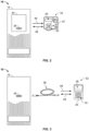
FIG. 1 is a schematic view of a motor drive and an external device, according to some embodiments. -
FIG. 2 is a schematic view of a motor drive directly connected to a Human Interface Module (HIM). -
FIG. 3 is a schematic view of a motor drive connected to an HIM via a connector cable. -
FIG. 4 is a schematic view of a motor drive connected to a personal computer via a connector cable -
FIG. 5 is a schematic view of a motor drive connected to a personal computer via an isolating connector cable. -
FIG. 6 illustrates a block diagram of control circuitry of a motor drive including a communications port, according to some embodiments. -
FIG. 7 is a schematic illustration of connector pins of a USB 3.1 connection port according to some embodiments. -
FIG. 8 is a flowchart of a method according to some embodiments. - Before any embodiments of the invention are explained in detail, it is to be understood that the embodiments are not limited in its application to the details of construction and the arrangement of components set forth in the following description or illustrated in the following drawings. Aspects of the present disclosure are capable of other embodiments and of being practiced or of being carried out in various ways. Also, it is to be understood that the phraseology and terminology used herein is for the purpose of description and should not be regarded as limiting. Furthermore, the use of "right", "left", "front", "back", "upper", "lower", "above", "below", "top", or "bottom" and variations thereof herein is for the purpose of description and should not be regarded as limiting. The use of "including," "comprising," or "having" and variations thereof herein is meant to encompass the items listed thereafter and equivalents thereof as well as additional items. Unless specified or limited otherwise, the terms "mounted," "connected," "supported," and "coupled" and variations thereof are used broadly and encompass both direct and indirect mountings, connections, supports, and couplings. Further, "connected" and "coupled" are not restricted to physical or mechanical connections or couplings.
- The following discussion is presented to enable a person skilled in the art to make and use embodiments of the present disclosure. Various modifications to the illustrated embodiments will be readily apparent to those skilled in the art, and the generic principles herein can be applied to other embodiments and applications without departing from embodiments of the present disclosure. Thus, embodiments of the present disclosure are not intended to be limited to embodiments shown, but are to be accorded the widest scope consistent with the principles and features disclosed herein. The following detailed description is to be read with reference to the figures, in which like elements in different figures have like reference numerals. The figures, which are not necessarily to scale, depict selected embodiments and are not intended to limit the scope of embodiments of the present disclosure. Skilled artisans will recognize the examples provided herein have many useful alternatives and fall within the scope of embodiments of the present disclosure.
- Disclosed herein are systems and methods for a motor drive including a dual-role universal serial bus (USB) port that supports dual-role data and/or dual-role power such that: (1) when a Human Interface Module (HIM) is connected to the dual-role USB port, the motor drive functions as a USB host providing power to the HIM and controlling data flow to and from the HIM, and (2) when a computer is connected to the dual-role USB port, the motor drive functions as a USB device receiving power from the computer and allowing the computer to control data flow to and from the motor drive. Additionally, in some embodiments, the motor drive can take one or more mitigation actions to prevent common mode noise between the motor drive and a connected computer when the motor drive is running.
- For example, some current drives support connections with external HIMs via proprietary cables and protocols having data communication rates that require significant time for updates and may be too slow to provide a satisfactory customer experience. Additionally, some current drives may support connection to a personal computer for "mains-free programming" (that is, when DC bus power of the drive is not present), but do so by requiring the power structure of the motor drive to be physically disconnected from the control structure. On the other hand, embodiments described herein use a USB dual-role port as a single, standard connection port for both HIM and personal computer connections without requiring drive power structures to be disconnected. In this manner, the motor drive can act as a USB dual-role power (DRP) device, providing the ability to negotiate power flow such that the motor drive operates as a source to provide power to an HIM or operates as a sink to receive power from a computer. Furthermore, the motor drive can act as a USB dual-role data (DRD) device, providing high-speed data communication rates with the ability to negotiate control of data flow such that the USB port operates as a downstream facing port (DFP), where the motor drive acts as a USB host, when connected to an HIM and operates as an upstream facing port (UFP), where the motor drive acts as a USB device, when connected to a computer.
- Accordingly,
FIG. 1 is a schematic view of amotor drive 10 and anexternal device 12, according to some embodiments. Themotor drive 10 can include anouter housing 14 that houses power and control circuitry such as, for example, apower module 16 and acontrol module 18. Themotor drive 10 can be connected to apower source 20 and configured to drive amotor 22. More specifically, in some embodiments, themotor drive 10 is adapted to receive three-phase power from thepower source 20 and convert this fixed frequency input power to a controlled frequency output power to be applied to themotor 22, as controlled by the power andcontrol modules motor drive 10 can be a PowerFlex drive manufactured by Rockwell Automation. - According to some embodiments, the
control module 18 is programmed according to a specific programming configuration desired for a particular application. That is, operating characteristics of themotor drive 10 may be determined, in part, by the programming configuration of themotor drive 10. For example, the programming configuration may include any data, software, or firmware that is used to define the performance of themotor drive 10, the appearance or performance of any user interfaces of themotor drive 10, or the performance or user interface appearance of any peripheral devices communicatively coupled to themotor drive 10. The programming configuration may include operating parameters, parameter customization data, and firmware for themotor drive 10 or any peripherals. Often, certain aspects of the programming configuration will be determined by a manufacturer, OEM, system integrator, or other service provider and transferred to themotor drive 10 from an external source. Furthermore, periodic updates of the programming configurations or operational codes may take place, such as when amotor drive 10 is replaced, themotor drive 10 application is altered, or firmware is updated. Accordingly, programming of thecontrol module 18 may be accomplished through software configuration or firmware code that is loaded onto an internal computer-readable memory 24 of thecontrol module 18 and accessed and/or executed by a microprocessor 26 (and/or one or more other processing devices, not shown) of thecontrol module 18. - Furthermore, the
motor drive 10 can be coupled to theexternal device 12, which can enable programming, monitoring, feedback, and/or control of themotor drive 10. According to some embodiments, theexternal device 12 can include adisplay 28, such as an LCD or other display device that may be used to provide feedback to the operator regarding the setting, performance or configuration of themotor drive 10. Theexternal device 12 can also include aninput structure 30, such as buttons, switches, touch pads, and/or a keypad, allowing input by a user. For example, theinput structure 30 may be used to provide operator control of themotor drive 10. As further described below, theexternal device 12 may be a human interface module 32 (HIM, such as a remote user interface or handheld user interface), as shown inFIGS. 2 and 3 , or a computer 34 (such as a personal computer, laptop, tablet, etc.), as shown inFIGS. 4 and 5 . - Referring still to
FIG. 1 , themotor drive 10 can include acommunications port 36 on theouter housing 14 that enables electronic communications between themotor drive 10 and theexternal device 12. For example, theexternal device 12 can be coupled to thecommunications port 36 via a connector 38 (e.g., a cable), as shown inFIG. 1 , or directly coupled to thecommunications port 36, e.g., via a plug (not shown) on theexternal device 12. Generally, thecommunications port 36 can support high data communication rates, such as a rate greater than 500 kilobits per second (kbps), a rate from 500 kbps up to 480 megabits per second (Mbps), a rate greater than 480 Mbps, a rate from 500 kbps up to 5 gigabits per second (Gbps), or a rate from 500 kbps up to 10 Gbps. Furthermore, thecommunications port 36 can include dual-role power (DRP) features that support bi-directional power flow, therefore permitting themotor drive 10 to act as a source, providing power to theexternal device 12, or permitting themotor drive 10 to act as a sink, being powered by theexternal device 12, with the ability to alternate between the source and sink roles. Additionally, thecommunications port 36 can include dual-role data (DRD) features that support bi-directional data flow, acting as a downstream facing port (DFP), permitting themotor drive 10 to act as a host relative to theexternal device 12, or acting as an upstream facing port (UFP), permitting themotor drive 10 to act as a device relative to the external device 12 (e.g., an external host), with the ability to alternate between the DFP and UFP roles. - In some embodiments, the
communications port 36 can be a USB port. Thecommunications port 36 can thus provi de a standard connector with means to allow USB endpoints (e.g., themotor drive 10 and/or the external device 12) to detect and negotiate host/device behavior, as further described below. For example, thecommunications port 36 can be a USB Type-A port, a USB Type-B port (including a micro USB port or a mini USB port), or a USB Type-C port. Furthermore, in some embodiments, thecommunications port 36 can be a USB 3.1 dual-role port. For example, in one embodiment, the USB 3.1 standard can support data rates up to 10 Gbps, or data rates up to 480 Mbps. Accordingly, theUSB port 36 can be used for data and power transfer between themotor drive 10 and theexternal device 12 when themotor drive 10 is coupled to theexternal device 12 via a direct connection, e.g., where theexternal device 12 includes a mating USB plug that can be plugged into theUSB port 36. As another example, as shown inFIG. 1 , theUSB port 36 can be used for data and power transfer between themotor drive 10 and theexternal device 12 when themotor drive 10 is coupled to theexternal device 12 via aUSB cable connection 38 between theUSB port 36 and acorresponding USB port 40 on theexternal device 12. - In light of the above,
FIGS. 2-5 illustrate various examples of themotor drive 10 coupled toexternal devices 12, according to some embodiments. More specifically,FIG. 2 illustrates amotor drive 10 directly connected to anHIM 32;FIG. 3 illustrates amotor drive 10 connected to anHIM 32 via a connector cable;FIG. 4 illustrates amotor drive 10 connected to apersonal computer 34 via a connector cable, andFIG. 5 illustrates amotor drive 10 connected to apersonal computer 34 via an isolating connector cable. It should be noted that any of the configurations illustrated inFIGS. 2-5 , or any other configurations described herein comprising amotor drive 10 and anexternal device 12, may be generally referred to as a motor drive system. - Referring now to
FIG. 2 , anHIM 32 can be directly connected to themotor drive 10. For example, as described above, themotor drive 10 includes aUSB port 36 on itsouter housing 14. TheHIM 32 can include a USB plug (not shown), for example along a rear side of itsouter housing 42, of the same type as theUSB port 36 on themotor drive 10, enabling a user to plug theHIM 32 into themotor drive 10 such that a USB cable is not required. In some embodiments, themotor drive 10 may also include areceptacle 44 to hold or support theHIM 32 when it is plugged into theUSB port 36. With this configuration, themotor drive 10 sources power to the HIM 32 (as shown by arrow 46) when themotor drive 10 is powered, and data flow is bi-directional (as shown by arrow 48) controlled by themotor drive 10. More specifically, with this configuration, themotor drive 10 acts as the power source and thecommunications port 36 is a USB DFP, while theHIM 32 acts as the power sink and includes a USB UFP. Themotor drive 10 may be powered to supply power to theHIM 32 using theexternal power source 20, shown inFIG. 1 , which powers a DC power bus of thepower module 16, or an auxiliary power supply (such as an auxiliary 24-volt power supply, not shown, that can be plugged into the motor drive 10). - Referring now to
FIG. 3 , anHIM 32 can be connected to themotor drive 10 via aconnector cable 38, such as a USB cable, that plugs into theUSB port 36 on theouter housing 14 of themotor drive 10 and into acorresponding USB port 40 on theHIM 32. Thus, theUSB cable 38 can include USB plugs of a type that mates with theUSB ports motor drive 10 and theHIM 32, respectively. In some embodiments, theUSB cable 38 is a USB Type-C cable. However, in other embodiments, theUSB cable 38 can include different respective USB plugs for themotor drive 10 and/or theHIM 32. For example, USB 3.1 is backward compatible with previous USB speeds (such as USB 2.0). Thus, while themotor drive 10 may include a USB 3.1 Type-C port 36, it may still be compatible with aHIM 32 including a USB 2.0port 40 or other older USB ports. With this configuration, themotor drive 10 sources power to the HIM 32 (as shown by arrow 46) when themotor drive 10 is powered, and data flow is bi-directional (as shown by arrow 48) controlled by themotor drive 10. More specifically, with this configuration, themotor drive 10 acts as the power source and thecommunications port 36 is a USB DFP, while theHIM 32 acts as the power sink and includes a USB UFP. Themotor drive 10 may be powered to supply power to theHIM 32 using theexternal power source 20, shown inFIG. 1 , which powers a DC power bus of the power module, or an auxiliary power supply. - Referring now to
FIG. 4 , acomputer 34 can be connected to themotor drive 10 via aconnector cable 38, such as a USB cable, that plugs into theUSB port 36 on theouter housing 14 of themotor drive 10 and into acorresponding USB port 40 on thecomputer 34. Thus, theUSB cable 38 can include USB plugs of a type that mates with theUSB ports motor drive 10 and thecomputer 34, respectively. In some embodiments, theUSB cable 36 is a USB Type-C cable. However, in other embodiments, theUSB cable 36 can include different USB plugs, as discussed above. With this configuration, thecomputer 34 sources power to the motor drive 10 (as shown by arrow 46), and data flow is bi-directional (as shown by arrow 48), controlled by thecomputer 34. More specifically, with this configuration, themotor drive 10 acts as the power sink and thecommunications port 36 is a USB UFP, while thecomputer 34 acts as the power source and includes a USB DFP. Accordingly, thecomputer 34 provides power to themotor drive 10, or at least to thecontrol module 16, to enable "mains-free programming," which may be considered programming of themotor drive 10 when power is not provided to the motor drive 10 (e.g., via thepower source 20 ofFIG. 1 or an auxiliary power source). That is, themotor drive 10 may not be able to power amotor 22 if themotor drive 10 is not receiving power from the power source 20 (or an auxiliary power source), but can still be powered by thecomputer 34 at least for programming, monitoring, feedback, and/or control. - Thus, generally, the
motor drive 10 may power amotor 22 when thecomputer 34 is coupled to themotor drive 10 for programming, monitoring, feedback, and/or control. However, thepower module 16 need not be physically separated from thecontrol module 16 to perform such programming, monitoring, feedback, and/or control. For example, in some embodiments, power may still be provided to themotor drive 10 via thepower source 20 to run aconnected motor 22 when thecomputer 34 is coupled to themotor drive 10. Furthermore, as further described below, in some embodiments, USB communication between themotor drive 10 and thecomputer 34 may be disabled when power to the motor drive 10 (e.g., via the power source) is detected. - Referring now to
FIG. 5 , acomputer 34 can be connected to themotor drive 10 via an isolatingconnector cable 50, such as a USB isolating cable, that plugs into theUSB port 36 on theouter housing 14 of themotor drive 10 and into acorresponding USB port 40 on thecomputer 34. Thus, theUSB isolating cable 50 can include USB plugs of a type that mates with the USB ports on themotor drive 10 and thecomputer 34, respectively. In some embodiments, theUSB isolating cable 50 is a USB Type-C isolating cable. However, in other embodiments, theUSB isolating cable 50 can include different USB plugs. Generally, the isolatingcable 50 can provide high-voltage isolation between two connected devices. Thus, with this configuration, themotor drive 10 and thecomputer 34 can each power their respective side of the isolating cable 50 (as shown by arrows 46), and data flow is bi-directional (as shown by arrows 48), controlled by thecomputer 34. More specifically, with this configuration, themotor drive 10 acts as a power source and thecommunications port 36 can be a USB UFP, while thecomputer 34 also acts as a power source and includes a USB DFP. Accordingly, power may still be provided to themotor drive 10 when thecomputer 34 is coupled to the motor drive 10 (e.g., via the power source ofFIG. 1 or an auxiliary power source). Additionally, in some embodiments, this configuration can include afirst USB cable 38 connected from themotor drive 10 to a separate USB isolator device (not shown) and asecond USB cable 38 connected from the USB isolator device to thecomputer 34. - In some embodiments, the
communications port 36 on themotor drive 10 can be coupled to other USB devices. For example, in one embodiment, thecommunications port 36 can be connected to a wireless USB dongle (not shown), which may be wirelessly connected to anexternal device 12. Accordingly, the USB dongle can act as a connector between themotor drive 10 and theexternal device 12. With this configuration, themotor drive 10 and theexternal device 12 are each respectively powered, and data flow is bi-directional, controlled by themotor drive 10 or theexternal device 12. As a result, themotor drive 10 and theexternal device 12 can communicate wirelessly, such as for wireless programming, monitoring, feedback, and/or control. - In light of these above examples, power direction and data control between the
motor drive 10 and theexternal device 12 can be dependent on the type ofexternal device 12. Thus, generally, themotor drive 10 can power theexternal device 12 when the external device is of a first type and themotor drive 10 receives power from theexternal device 12 when theexternal device 12 is of a second type. Additionally, themotor drive 10 can control data transmission to theexternal device 12 when theexternal device 12 is of a first type and themotor drive 10 can allow theexternal device 12 to control data transmission when theexternal device 12 is of a second type. It should also be noted that power delivery and control of data flow can be independent. As a result, in some embodiments, the following power and data flow configurations can be achieved: (1) themotor drive 10 can supply power and control data flow; (2) themotor drive 10 can receive power and control data flow; (3) the external device can supply power and control data flow; and/or (4) the external device can receive power and control data flow. - Accordingly, as described above, in some embodiments, the
motor drive 10 includes a USB 3 1 dual-role communications port 36 on itsouter housing 14 for connection to anexternal device 12. For example,FIG. 6 illustrates a block diagram of control circuitry of themotor drive 10 and thecommunications port 36, according to some embodiments. Such control circuitry can be part of thecontrol module 18, in some embodiments. As shown inFIG. 6 , the control circuitry can include themicroprocessor 26,voltage regulators 52, a drivevoltage detection circuit 54, a computervoltage detection circuit 56, aUSB power multiplexor 58, and a configuration channel (CC)logic controller 60. - Still referring to
FIG. 6 , theUSB power multiplexor 58 can provide control over sourcing power to or receiving power from theexternal device 12. TheCC logic controller 60 can manage monitoring and negotiation of connections with theexternal device 12. TheCC logic controller 60 can also provide partial control of theUSB power multiplexor 58 to enable drive power-up for mains-free programming. Thevoltage regulators 52 can be used for logic and communications functions of themotor drive 10 and can be supplied by external power from theexternal device 12 and power from thepower module 16 of themotor drive 10. Themicroprocessor 26 can, among other things, monitor a connection status of potential power sources, via the drivevoltage detection circuit 54 and the computervoltage detection circuit 56, transmit and receive data with the USB-connectedexternal device 12, control theUSB power multiplexor 58, communicate with theCC controller 60, e.g., to receive connection status, and provide indicator control, for example, to an indicator 62 (such as a light-emitting diode, LED) on theouter housing 14, as further described below. - Additionally,
FIG. 7 is a schematic illustration of connector pins of a USB 3.1connection port 36 according to some embodiments. With reference toFIGS. 6 and7 , D+ and D-pins can be used for data transmission, connected to themicroprocessor 26. VBUS and GND pins can be used for power delivery, where VBUS pins (e.g., cable bus power) are connected to theUSB power multiplexor 58. CC1 and CC2 pins can be used for connection and orientation detection, connected to theCC controller 60. That is, the CC pins can be monitored to determine what is connected to thecommunications port 36, e.g., based on pull-up resistors (indicating a USB host or DFP), pull-down resistors (indicating a USB device or UFP) on the CC pins, or an ability to configure either pull-up or pull-down (indicating a dual-role data (DRD) device). As such, changes in data or power delivery roles can be communicated over the CC line. - It should be noted that, while USB 3.1 Type-C connections are shown and described above with respect to the motor
drive communications port 36, certain features may be utilized with older USB versions. Furthermore, as noted above, theexternal device 12 may include a differentUSB type port 36. In such cases, data speeds may be governed by the older USB type port andconnector cable 38. For example, USB 3. 1 is backward compatible with previous USB speeds, such as USB 2.0 speeds (e.g., up to 480 Mbps), via the D+/D- data lines. Furthermore, while single communications ports are shown and described herein, in some embodiments, themotor drive 10 may includemultiple USB ports 36 and/or theHIM 32 and/or thecomputer 34 may include multiple USB ports 40 (e.g., to connect to multiple motor drives 10). For example, in one embodiment, themotor drive 10 may includemultiple USB ports 36 and, as a result, maybe connected to anHIM 32 and apersonal computer 34 simultaneously. - Accordingly, via the control circuitry and physical cable interconnection logic, the
motor drive 10 is able to determine what type ofexternal device 12 is connected so that it may operate as a power source or power sink, or UFP or DFP, as described above. For example, as described above, themotor drive 10 can monitor USB connection status, e.g., via theCC controller 60, and themotor drive 10 can monitor its DC bus to determine power supply status, e.g., via the voltage detection circuits, as further described below. In some embodiments, common mode noise is generated by amotor drive 10 powering (e.g., running or operating) amotor 22. Such common mode noise can interfere with proper operation of connected chassis-groundedexternal devices 12, such as a computer 34 (though, generally, such noise may not cause safety issues as thecontrol module 18 of themotor drive 10 may also be chassis grounded to earth ground). As a result, in some embodiments, themotor drive 10 may be further programmed to take actions when acomputer 34 is connected to thecommunications port 36 and themotor drive 10 is operating. For example, one action may be to inhibit motor start until thecomputer 34 is disconnected from thecommunications port 36. As another example, one action may be to inhibit USB communication when acomputer 34 is connected to thecommunications port 36 while themotor drive 10 is already running. As yet another example, one action may be to provide an alert when acomputer 34 is connected to thecommunications port 36 while themotor drive 10 is already running, or when acomputer 34 is connected to thecommunications port 36 and themotor drive 10 is instructed to start themotor 22. Such alerts may be a visual warning message or audio warning through a user interface on the motor drive 10 (e.g., themotor drive 10 may include an embedded HIM with adisplay 28 and/or speaker), a visual warning through anLED 62 located on theouter housing 14, such as by thecommunications port 36, on the user interface, or at another location on thehousing 14, and/or a warning through thedisplay 28 of thecomputer 34. - In light of the above,
FIG. 8 illustrates amethod 70 according to some embodiments. Generally, one or more steps of themethod 70 can be executed by themotor drive 10 or, more specifically, thecontrol module 18 or, more specifically, themicroprocessor 26. Thus, any of the steps described herein may be considered to be carried out by themotor drive 10, thecontrol module 18, and/or themicroprocessor 26. For example, one or more steps of themethod 70 may be part of a program stored inmemory 24 and executed by themicroprocessor 26 Additionally, while the steps of themethod 70 are shown in a particular order, in some embodiments, themethod 70 may not include all steps shown, may include additional steps, or may include the steps in a different order. - Referring still to
FIG. 8 , generally, atstep 72 themotor drive 10 can determine whether an external device is connected. If not, atstep 74, normal drive operation can be enabled and the method returns to step 72. If, atstep 72, an external device connection is detected, the USB-connected device type can be determined atstep 76. The external device type can be a USB host, such as acomputer 34 or a USB device, such as anHIM 32, a wireless dongle, etc. - If, at
step 76, a USB device is detected, themotor drive 10 can act as a host with a DFP. Accordingly, atstep 78, power can be provided from themotor drive 10 to the USB device. By determining external device connection prior to enabling USB bus power to theexternal device 12, the motor drive 10 (via the USB 3.1 port 36) can help prevent short circuits from occurring, for example, if two hosts were connected. Atstep 80, themotor drive 10 and the USB device can communicate, with data communication controlled by themotor drive 10. Power and/or data communication between themotor drive 10 and the USB device can continue until the USB device is disconnected, as determined atstep 82. When the USB device is disconnected, themotor drive 10 returns to step 72 to again look for an external device connection. - If, at
step 76, a USB host is detected, the motor drive can act as a device with a UFP. Accordingly, atstep 84, the connection type may be determined. If, atstep 84, the USB host is connected to themotor drive 10 via an isolated connection, then isolated power is provided by both themotor drive 10 and the USB host atstep 86. Atstep 88, themotor drive 10 and the USB host can communicate, with data communication controlled by the USB host. Power and/or data communication between themotor drive 10 and the USB host can continue until the USB host is disconnected, as determined atstep 90. When the USB host is disconnected, themotor drive 10 returns to step 72 to again look for an external device connection. - If, at
step 84, the USB host is connected to themotor drive 10 without an isolated connection, motor drive power supply status is determined atstep 92. That is, atstep 92, themicroprocessor 26 can determine whether themotor drive 10 is running aconnected motor 22 or received instruction to start running aconnected motor 22. If themotor 22 is not running and no motor start instruction is received, as determined atstep 92, power is provided from the USB host to the motor drive atstep 94. Atstep 96, themotor drive 10 and the USB host can communicate, with data communication controlled by the USB host. Power and/or data communication between themotor drive 10 and the USB host can continue until the USB host is disconnected, as determined atstep 98. When the USB host is disconnected, themotor drive 10 returns to step 72 to again look for an external device connection. - Thus, if the USB host remains connected, the
motor drive 10 can return to step 94, or return to step 92. If, at step 92 (e.g., followingstep 84 or step 98), themotor 22 is running or a motor start instruction is received, common mode noise mitigation actions may be taken atstep 100. In some embodiments, such actions atstep 100 may include inhibiting power and/or data communication between themotor drive 10 and the USB host, such thatsteps 94 and/or 96 are skipped. In some embodiments, such actions atstep 100 may include inhibiting themotor 22 from being started, such that power and/or data communication between themotor drive 10 and the USB host atstep step 100 may include providing an alert or warning only (e.g., via a display or LED indicator), such that power and/or data communication between themotor drive 10 and the USB host atstep motor drive 10 may be able to run while the USB host is connected and communicating with themotor drive 10, but a user may be alerted and, for example, encouraged to disconnect the USB host from themotor drive 10 during motor operation. - Additionally or alternatively, in some embodiments, at
step 92, motor drive power supply status can be determined by sensing a DC bus line of themotor drive 10. The DC bus in themotor drive 10 can be monitored to determine whether an isolated connection is necessary to the USB host. For example, if DC bus is present, isolation may be required to the USB host and, if isolation is not present, firmware algorithms in themotor drive 10 can prohibit any motor operations from any source. If DC bus is not present, USB power from the USB host can be used to operate various low voltage parts of themotor drive 10 including, but not limited to, processors to flash thedrive 10 or to read/write the configurations of the drive 10 (e.g., atsteps 94 and 96). - In light of the above, some embodiments provide a motor drive comprising USB dual-role data and/or dual-role power, with a common port for connections to external devices including USB devices (e.g., a USB HIM, a USB wireless dongle, etc.) and USB hosts (e.g., a personal computer, a laptop, a tablet, etc.). Through this common port, the USB devices may be powered by the drive, while the USB hosts may provide power to the drive (e.g., for mains-free programming). In some embodiments, the motor drive can detect situations in which common mode noise may interfere with operations of the attached external devices and take mitigation actions to prevent that interference. Additionally, the common USB port can provide high data communication rates. Such high data communication rates can be advantageous, for example, to reduce time required for motor drive firmware and configuration updates as well as to enable HIM features such as, but not limited to, wireless access via Bluetooth or WiFi, high-speed data transfers, and/or graphical trending. Furthermore, while the features and advantages of a dual-role USB port for programming a motor drive via an HIM or personal computer are described and illustrated herein, such features and advantages can also be applied to other components of industrial control systems such as, but not limited to, motor control centers, soft starters, or smart breakers.
- In the preceding specification, various embodiments have been described with reference to the accompanying drawings. It will, however, be evident that various modifications and changes may be made thereto, and additional embodiments may be implemented, without departing from the broader scope of the invention as set forth in the claims that follow. The specification and drawings are accordingly to be regarded in an illustrative rather than restrictive sense.
- The following is a list of further embodiments of the invention:
-
Embodiment 1. A motor drive configured to be connected to an external device, the motor drive comprising:- an outer housing;
- a power module housed within the outer housing;
- a control module housed within the outer housing and in communication with the power module; and
- a communications port disposed on the outer housing and in communication with the control module, the communications port supporting dual-role power in which the motor drive powers the external device when the external device is of a first type and the motor drive receives power from the external device when the external device is of a second type.
-
Embodiment 2. The motor drive ofembodiment 1, wherein the communications port supports dual-role data flow in which the motor drive controls data transmission to the external device when the external device is of the first type and the motor drive allows the external device to control data transmission when the external device is of the second type. - Embodiment 3. The motor drive of
embodiment 2, wherein the communications port is a USB port. - Embodiment 4. The motor drive of embodiment 3, wherein the communications port is a USB 3.1, Type-C port.
- Embodiment 5. The motor drive of
embodiment 2, wherein the first type includes at least one USB device chosen from a human interface module and a wireless USB dongle. - Embodiment 6. The motor drive of
embodiment 2, wherein the second type includes at least one USB host chosen from a personal computer, a tablet, and a laptop. - Embodiment 7. The motor drive of
embodiment 1, wherein the control module is configured to:- detect when the external device is detected, and
- determine whether the external device is of the first type or the second type.
- Embodiment 8. A motor drive system, the motor drive system comprising:
- a motor drive comprising:
- an outer housing,
- a power module housed within the outer housing,
- a control module housed within the outer housing and in communication with the power module, and
- a USB port disposed on the outer housing and in communication with the control module; and
- a human interface module removably coupled to the motor drive via the USB port.
- a motor drive comprising:
- Embodiment 9. The motor drive system of embodiment 8, wherein the human interface module includes a plug that directly connects to the USB port of the motor drive.
-
Embodiment 10. The motor drive system of embodiment 9, wherein the outer housing includes a receptacle that supports the human interface module. - Embodiment 11. The motor drive system of embodiment 8, wherein the human interface module includes a port and is coupled to the motor drive via a USB connector cable that plugs into both the USB port of the motor drive and into the port of the human interface module.
-
Embodiment 12. The motor drive system of embodiment 8, wherein the USB port supports dual-role power flow in which:- the motor drive powers the human interface module when the human interface module is coupled to the motor drive, and
- a personal computer powers the motor drive when the personal computer is coupled to the motor drive via the USB port.
- Embodiment 13. The motor drive system of embodiment 8, wherein the USB port supports dual-role data flow in which:
- the motor drive controls data transmission between the motor drive and the human interface module when the human interface module is coupled to the motor drive, and
- a personal computer controls data transmission between the motor drive and the personal computer when the personal computer is coupled to the motor drive via the USB port.
-
Embodiment 14. A method of operating a motor drive, the method comprising:- determining a USB host is connected to the motor drive via a USB port on the motor drive;
- enabling the USB host to provide power to the motor drive when the USB host is connected to the motor drive; and
- taking a common mode noise mitigation action when a motor connected to the motor drive is to be run.
- Embodiment 15. The method of
embodiment 14, wherein taking the common mode noise mitigation action includes preventing the motor from starting until the USB host is disconnected from the motor drive. -
Embodiment 16. The method ofembodiment 14, wherein taking the common mode noise mitigation action includes displaying an alert on a user interface of the motor drive. - Embodiment 17. The method of
embodiment 14, wherein taking the common mode noise mitigation action includes displaying an alert on a user interface of the USB host. -
Embodiment 18. The method ofembodiment 14, wherein taking the common mode noise mitigation action includes activating an indicator on the motor drive. - Embodiment 19. The method of
embodiment 18, wherein activating the indicator includes flashing an LED on the motor drive. -
Embodiment 20. The method ofembodiment 14, wherein taking the common mode noise mitigation action includes preventing data communication between the USB host and the motor drive.
Claims (15)
- A motor drive configured to be connected to an external device, the motor drive comprising:an outer housing;a power module housed within the outer housing;a control module housed within the outer housing and in communication with the power module; anda communications port disposed on the outer housing and in communication with the control module, the communications port supporting dual-role power in which the motor drive powers the external device when the external device is of a first type and the motor drive receives power from the external device when the external device is of a second type.
- The motor drive of claim 1, wherein the communications port supports dual-role data flow in which the motor drive controls data transmission to the external device when the external device is of the first type and the motor drive allows the external device to control data transmission when the external device is of the second type.
- The motor drive of claim 2, wherein the communications port is a USB port.
- The motor drive of claim 3, wherein the communications port is a USB 3.1, Type-C port.
- The motor drive of claim 2, wherein the first type includes at least one USB device chosen from a human interface module and a wireless USB dongle; or
wherein the second type includes at least one USB host chosen from a personal computer, a tablet, and a laptop. - The motor drive of one of claims 1 to 5, wherein the control module is configured to:detect when the external device is detected, anddetermine whether the external device is of the first type or the second type.
- A motor drive system, the motor drive system comprising:
a motor drive comprising:an outer housing,a power module housed within the outer housing,a control module housed within the outer housing and in communication with the power module, anda USB port disposed on the outer housing and in communication with the control module; anda human interface module removably coupled to the motor drive via the USB port. - The motor drive system of claim 7, wherein the human interface module includes a plug that directly connects to the USB port of the motor drive; and/or
wherein the outer housing includes a receptacle that supports the human interface module. - The motor drive system of one of claim 7 or 8, wherein the human interface module includes a port and is coupled to the motor drive via a USB connector cable that plugs into both the USB port of the motor drive and into the port of the human interface module.
- The motor drive system of one of claims 7 to 9, wherein the USB port supports dual-role power flow in which:the motor drive powers the human interface module when the human interface module is coupled to the motor drive, anda personal computer powers the motor drive when the personal computer is coupled to the motor drive via the USB port.
- The motor drive system of one of claims 7 to 10, wherein the USB port supports dual-role data flow in which:the motor drive controls data transmission between the motor drive and the human interface module when the human interface module is coupled to the motor drive, anda personal computer controls data transmission between the motor drive and the personal computer when the personal computer is coupled to the motor drive via the USB port.
- A method of operating a motor drive, the method comprising:determining a USB host is connected to the motor drive via a USB port on the motor drive;enabling the USB host to provide power to the motor drive when the USB host is connected to the motor drive; andtaking a common mode noise mitigation action when a motor connected to the motor drive is to be run.
- The method of claim 12, wherein taking the common mode noise mitigation action includes preventing the motor from starting until the USB host is disconnected from the motor drive; orwherein taking the common mode noise mitigation action includes displaying an alert on a user interface of the motor drive; orwherein taking the common mode noise mitigation action includes displaying an alert on a user interface of the USB host.
- The method of one of claims 12 or 13, wherein taking the common mode noise mitigation action includes activating an indicator on the motor drive; and/or
wherein activating the indicator includes flashing an LED on the motor drive. - The method of one of claims 12 to 14, wherein taking the common mode noise mitigation action includes preventing data communication between the USB host and the motor drive.
Applications Claiming Priority (2)
| Application Number | Priority Date | Filing Date | Title |
|---|---|---|---|
| US202263357184P | 2022-06-30 | 2022-06-30 | |
| US17/872,991 US20240006953A1 (en) | 2022-06-30 | 2022-07-25 | Motor drive with dual-role usb port and methods thereof |
Publications (3)
| Publication Number | Publication Date |
|---|---|
| EP4300318A2 true EP4300318A2 (en) | 2024-01-03 |
| EP4300318A3 EP4300318A3 (en) | 2024-01-24 |
| EP4300318B1 EP4300318B1 (en) | 2025-07-30 |
Family
ID=86904283
Family Applications (1)
| Application Number | Title | Priority Date | Filing Date |
|---|---|---|---|
| EP23180280.2A Active EP4300318B1 (en) | 2022-06-30 | 2023-06-20 | Motor drive with dual-role usb port and methods thereof |
Country Status (2)
| Country | Link |
|---|---|
| US (1) | US20240006953A1 (en) |
| EP (1) | EP4300318B1 (en) |
Family Cites Families (3)
| Publication number | Priority date | Publication date | Assignee | Title |
|---|---|---|---|---|
| CN201137575Y (en) * | 2007-10-05 | 2008-10-22 | 沈敏毅 | USB fan |
| WO2014116761A1 (en) * | 2013-01-23 | 2014-07-31 | Trane International Inc. | Variable frequency drive self-check |
| KR20160092671A (en) * | 2015-01-28 | 2016-08-05 | 삼성전자주식회사 | Electronic device and method for managing power |
-
2022
- 2022-07-25 US US17/872,991 patent/US20240006953A1/en active Pending
-
2023
- 2023-06-20 EP EP23180280.2A patent/EP4300318B1/en active Active
Also Published As
| Publication number | Publication date |
|---|---|
| EP4300318A3 (en) | 2024-01-24 |
| US20240006953A1 (en) | 2024-01-04 |
| EP4300318B1 (en) | 2025-07-30 |
Similar Documents
| Publication | Publication Date | Title |
|---|---|---|
| CN102315576B (en) | Power distribution within cables | |
| US7489974B2 (en) | Information processing apparatus and method for controlling power supply of the apparatus | |
| EP2069880B1 (en) | Method and device for activating functions of a powered-off device via a serial data bus interface | |
| EP3178007B1 (en) | Methods, electronic devices, and charger apparatus for quick usb charging | |
| EP1550045B1 (en) | Device operable as both a host and a non-host (i.e. dual-mode device) | |
| EP2498167B1 (en) | Multiple connections to a single serial interface | |
| US7886104B2 (en) | Detachable adapter and portable system | |
| US20080150512A1 (en) | Electronic device | |
| US20040063464A1 (en) | High-speed data and power source interface cable for mobile devices | |
| EP1150525A2 (en) | Mobile communication terminal device | |
| JP6752675B2 (en) | Semiconductor devices, control methods for semiconductor devices, and semiconductor systems | |
| US8589597B2 (en) | Computer having removable input/output device | |
| CN108228509B (en) | USB interface switching device and electronic equipment | |
| CN109672950B (en) | Power saving circuit and power saving method based on Type-C earphone | |
| KR20140027842A (en) | Accessory device for supporting a hierarchical connection and system, and supporting method thereof | |
| KR20190047526A (en) | A method for performing communication via input output interface and a method thereof | |
| WO2018096798A1 (en) | Function extension device, information processing system, and control program of function extension device | |
| US20240006953A1 (en) | Motor drive with dual-role usb port and methods thereof | |
| CN117335612A (en) | Motor driver with dual-role USB port and operation method thereof | |
| JP2001306413A (en) | USB communication device | |
| CN110489364A (en) | Output equipment and output equipment control method | |
| KR101678556B1 (en) | Apparatus for control multiple access of USB device | |
| WO2008065468A1 (en) | Power control for serial bus peripheral device | |
| CN108513656A (en) | Control method, USB system and electronic device | |
| JP5008088B2 (en) | Display system, display control apparatus, and computer program |
Legal Events
| Date | Code | Title | Description |
|---|---|---|---|
| PUAI | Public reference made under article 153(3) epc to a published international application that has entered the european phase |
Free format text: ORIGINAL CODE: 0009012 |
|
| STAA | Information on the status of an ep patent application or granted ep patent |
Free format text: STATUS: THE APPLICATION HAS BEEN PUBLISHED |
|
| PUAL | Search report despatched |
Free format text: ORIGINAL CODE: 0009013 |
|
| AK | Designated contracting states |
Kind code of ref document: A2 Designated state(s): AL AT BE BG CH CY CZ DE DK EE ES FI FR GB GR HR HU IE IS IT LI LT LU LV MC ME MK MT NL NO PL PT RO RS SE SI SK SM TR |
|
| AK | Designated contracting states |
Kind code of ref document: A3 Designated state(s): AL AT BE BG CH CY CZ DE DK EE ES FI FR GB GR HR HU IE IS IT LI LT LU LV MC ME MK MT NL NO PL PT RO RS SE SI SK SM TR |
|
| RIC1 | Information provided on ipc code assigned before grant |
Ipc: H02P 29/00 20160101ALI20231218BHEP Ipc: G05B 9/02 20060101ALI20231218BHEP Ipc: G05B 19/406 20060101ALI20231218BHEP Ipc: H02M 1/44 20070101ALI20231218BHEP Ipc: G06F 13/10 20060101ALI20231218BHEP Ipc: G06F 1/26 20060101ALI20231218BHEP Ipc: G06F 13/42 20060101ALI20231218BHEP Ipc: H04L 12/40 20060101ALI20231218BHEP Ipc: H04L 12/10 20060101ALI20231218BHEP Ipc: G06F 13/40 20060101ALI20231218BHEP Ipc: G06F 13/38 20060101AFI20231218BHEP |
|
| STAA | Information on the status of an ep patent application or granted ep patent |
Free format text: STATUS: REQUEST FOR EXAMINATION WAS MADE |
|
| 17P | Request for examination filed |
Effective date: 20240716 |
|
| RBV | Designated contracting states (corrected) |
Designated state(s): AL AT BE BG CH CY CZ DE DK EE ES FI FR GB GR HR HU IE IS IT LI LT LU LV MC ME MK MT NL NO PL PT RO RS SE SI SK SM TR |
|
| GRAP | Despatch of communication of intention to grant a patent |
Free format text: ORIGINAL CODE: EPIDOSNIGR1 |
|
| STAA | Information on the status of an ep patent application or granted ep patent |
Free format text: STATUS: GRANT OF PATENT IS INTENDED |
|
| RIC1 | Information provided on ipc code assigned before grant |
Ipc: H02M 1/12 20060101ALI20250128BHEP Ipc: H02P 29/00 20160101ALI20250128BHEP Ipc: G05B 9/02 20060101ALI20250128BHEP Ipc: G05B 19/406 20060101ALI20250128BHEP Ipc: H02M 1/44 20070101ALI20250128BHEP Ipc: G06F 13/10 20060101ALI20250128BHEP Ipc: G06F 1/26 20060101ALI20250128BHEP Ipc: G06F 13/42 20060101ALI20250128BHEP Ipc: H04L 12/40 20060101ALI20250128BHEP Ipc: H04L 12/10 20060101ALI20250128BHEP Ipc: G06F 13/40 20060101ALI20250128BHEP Ipc: G06F 13/38 20060101AFI20250128BHEP |
|
| INTG | Intention to grant announced |
Effective date: 20250207 |
|
| GRAS | Grant fee paid |
Free format text: ORIGINAL CODE: EPIDOSNIGR3 |
|
| GRAA | (expected) grant |
Free format text: ORIGINAL CODE: 0009210 |
|
| STAA | Information on the status of an ep patent application or granted ep patent |
Free format text: STATUS: THE PATENT HAS BEEN GRANTED |
|
| AK | Designated contracting states |
Kind code of ref document: B1 Designated state(s): AL AT BE BG CH CY CZ DE DK EE ES FI FR GB GR HR HU IE IS IT LI LT LU LV MC ME MK MT NL NO PL PT RO RS SE SI SK SM TR |
|
| REG | Reference to a national code |
Ref country code: GB Ref legal event code: FG4D |
|
| REG | Reference to a national code |
Ref country code: CH Ref legal event code: EP |
|
| REG | Reference to a national code |
Ref country code: DE Ref legal event code: R096 Ref document number: 602023005175 Country of ref document: DE |
|
| REG | Reference to a national code |
Ref country code: IE Ref legal event code: FG4D |
|
| REG | Reference to a national code |
Ref country code: NL Ref legal event code: MP Effective date: 20250730 |
|
| REG | Reference to a national code |
Ref country code: AT Ref legal event code: MK05 Ref document number: 1819757 Country of ref document: AT Kind code of ref document: T Effective date: 20250730 |
|
| PG25 | Lapsed in a contracting state [announced via postgrant information from national office to epo] |
Ref country code: PT Free format text: LAPSE BECAUSE OF FAILURE TO SUBMIT A TRANSLATION OF THE DESCRIPTION OR TO PAY THE FEE WITHIN THE PRESCRIBED TIME-LIMIT Effective date: 20251202 |
|
| PG25 | Lapsed in a contracting state [announced via postgrant information from national office to epo] |
Ref country code: IS Free format text: LAPSE BECAUSE OF FAILURE TO SUBMIT A TRANSLATION OF THE DESCRIPTION OR TO PAY THE FEE WITHIN THE PRESCRIBED TIME-LIMIT Effective date: 20251130 |
|
| PG25 | Lapsed in a contracting state [announced via postgrant information from national office to epo] |
Ref country code: NO Free format text: LAPSE BECAUSE OF FAILURE TO SUBMIT A TRANSLATION OF THE DESCRIPTION OR TO PAY THE FEE WITHIN THE PRESCRIBED TIME-LIMIT Effective date: 20251030 |
|
| REG | Reference to a national code |
Ref country code: LT Ref legal event code: MG9D |
|
| PG25 | Lapsed in a contracting state [announced via postgrant information from national office to epo] |
Ref country code: AT Free format text: LAPSE BECAUSE OF FAILURE TO SUBMIT A TRANSLATION OF THE DESCRIPTION OR TO PAY THE FEE WITHIN THE PRESCRIBED TIME-LIMIT Effective date: 20250730 |
|
| PG25 | Lapsed in a contracting state [announced via postgrant information from national office to epo] |
Ref country code: FI Free format text: LAPSE BECAUSE OF FAILURE TO SUBMIT A TRANSLATION OF THE DESCRIPTION OR TO PAY THE FEE WITHIN THE PRESCRIBED TIME-LIMIT Effective date: 20250730 |
|
| PG25 | Lapsed in a contracting state [announced via postgrant information from national office to epo] |
Ref country code: HR Free format text: LAPSE BECAUSE OF FAILURE TO SUBMIT A TRANSLATION OF THE DESCRIPTION OR TO PAY THE FEE WITHIN THE PRESCRIBED TIME-LIMIT Effective date: 20250730 Ref country code: NL Free format text: LAPSE BECAUSE OF FAILURE TO SUBMIT A TRANSLATION OF THE DESCRIPTION OR TO PAY THE FEE WITHIN THE PRESCRIBED TIME-LIMIT Effective date: 20250730 |
|
| PG25 | Lapsed in a contracting state [announced via postgrant information from national office to epo] |
Ref country code: GR Free format text: LAPSE BECAUSE OF FAILURE TO SUBMIT A TRANSLATION OF THE DESCRIPTION OR TO PAY THE FEE WITHIN THE PRESCRIBED TIME-LIMIT Effective date: 20251031 |
|
| PG25 | Lapsed in a contracting state [announced via postgrant information from national office to epo] |
Ref country code: SE Free format text: LAPSE BECAUSE OF FAILURE TO SUBMIT A TRANSLATION OF THE DESCRIPTION OR TO PAY THE FEE WITHIN THE PRESCRIBED TIME-LIMIT Effective date: 20250730 |
|
| PG25 | Lapsed in a contracting state [announced via postgrant information from national office to epo] |
Ref country code: LV Free format text: LAPSE BECAUSE OF FAILURE TO SUBMIT A TRANSLATION OF THE DESCRIPTION OR TO PAY THE FEE WITHIN THE PRESCRIBED TIME-LIMIT Effective date: 20250730 |
|
| PG25 | Lapsed in a contracting state [announced via postgrant information from national office to epo] |
Ref country code: BG Free format text: LAPSE BECAUSE OF FAILURE TO SUBMIT A TRANSLATION OF THE DESCRIPTION OR TO PAY THE FEE WITHIN THE PRESCRIBED TIME-LIMIT Effective date: 20250730 Ref country code: PL Free format text: LAPSE BECAUSE OF FAILURE TO SUBMIT A TRANSLATION OF THE DESCRIPTION OR TO PAY THE FEE WITHIN THE PRESCRIBED TIME-LIMIT Effective date: 20250730 |
|
| PG25 | Lapsed in a contracting state [announced via postgrant information from national office to epo] |
Ref country code: RS Free format text: LAPSE BECAUSE OF FAILURE TO SUBMIT A TRANSLATION OF THE DESCRIPTION OR TO PAY THE FEE WITHIN THE PRESCRIBED TIME-LIMIT Effective date: 20251030 |
|
| PG25 | Lapsed in a contracting state [announced via postgrant information from national office to epo] |
Ref country code: ES Free format text: LAPSE BECAUSE OF FAILURE TO SUBMIT A TRANSLATION OF THE DESCRIPTION OR TO PAY THE FEE WITHIN THE PRESCRIBED TIME-LIMIT Effective date: 20250730 |
|
| PG25 | Lapsed in a contracting state [announced via postgrant information from national office to epo] |
Ref country code: SM Free format text: LAPSE BECAUSE OF FAILURE TO SUBMIT A TRANSLATION OF THE DESCRIPTION OR TO PAY THE FEE WITHIN THE PRESCRIBED TIME-LIMIT Effective date: 20250730 |
|
| PG25 | Lapsed in a contracting state [announced via postgrant information from national office to epo] |
Ref country code: DK Free format text: LAPSE BECAUSE OF FAILURE TO SUBMIT A TRANSLATION OF THE DESCRIPTION OR TO PAY THE FEE WITHIN THE PRESCRIBED TIME-LIMIT Effective date: 20250730 |
|
| PG25 | Lapsed in a contracting state [announced via postgrant information from national office to epo] |
Ref country code: IT Free format text: LAPSE BECAUSE OF FAILURE TO SUBMIT A TRANSLATION OF THE DESCRIPTION OR TO PAY THE FEE WITHIN THE PRESCRIBED TIME-LIMIT Effective date: 20250730 |
|
| PG25 | Lapsed in a contracting state [announced via postgrant information from national office to epo] |
Ref country code: CZ Free format text: LAPSE BECAUSE OF FAILURE TO SUBMIT A TRANSLATION OF THE DESCRIPTION OR TO PAY THE FEE WITHIN THE PRESCRIBED TIME-LIMIT Effective date: 20250730 |
|
| PG25 | Lapsed in a contracting state [announced via postgrant information from national office to epo] |
Ref country code: EE Free format text: LAPSE BECAUSE OF FAILURE TO SUBMIT A TRANSLATION OF THE DESCRIPTION OR TO PAY THE FEE WITHIN THE PRESCRIBED TIME-LIMIT Effective date: 20250730 Ref country code: SK Free format text: LAPSE BECAUSE OF FAILURE TO SUBMIT A TRANSLATION OF THE DESCRIPTION OR TO PAY THE FEE WITHIN THE PRESCRIBED TIME-LIMIT Effective date: 20250730 |