EP4300243A1 - Travelling vehicle and travelling vehicle system - Google Patents
Travelling vehicle and travelling vehicle system Download PDFInfo
- Publication number
- EP4300243A1 EP4300243A1 EP22762846.8A EP22762846A EP4300243A1 EP 4300243 A1 EP4300243 A1 EP 4300243A1 EP 22762846 A EP22762846 A EP 22762846A EP 4300243 A1 EP4300243 A1 EP 4300243A1
- Authority
- EP
- European Patent Office
- Prior art keywords
- travelling vehicle
- travelling
- region
- marker
- vehicle
- Prior art date
- Legal status (The legal status is an assumption and is not a legal conclusion. Google has not performed a legal analysis and makes no representation as to the accuracy of the status listed.)
- Granted
Links
Images




Classifications
-
- H—ELECTRICITY
- H10—SEMICONDUCTOR DEVICES; ELECTRIC SOLID-STATE DEVICES NOT OTHERWISE PROVIDED FOR
- H10P—GENERIC PROCESSES OR APPARATUS FOR THE MANUFACTURE OR TREATMENT OF DEVICES COVERED BY CLASS H10
- H10P72/00—Handling or holding of wafers, substrates or devices during manufacture or treatment thereof
- H10P72/06—Apparatus for monitoring, sorting, marking, testing or measuring
- H10P72/0606—Position monitoring, e.g. misposition detection or presence detection
-
- B—PERFORMING OPERATIONS; TRANSPORTING
- B61—RAILWAYS
- B61L—GUIDING RAILWAY TRAFFIC; ENSURING THE SAFETY OF RAILWAY TRAFFIC
- B61L25/00—Recording or indicating positions or identities of vehicles or trains or setting of track apparatus
- B61L25/02—Indicating or recording positions or identities of vehicles or trains
- B61L25/04—Indicating or recording train identities
-
- B—PERFORMING OPERATIONS; TRANSPORTING
- B61—RAILWAYS
- B61L—GUIDING RAILWAY TRAFFIC; ENSURING THE SAFETY OF RAILWAY TRAFFIC
- B61L15/00—Indicators provided on the vehicle or train for signalling purposes
- B61L15/0058—On-board optimisation of vehicle or vehicle train operation
-
- B—PERFORMING OPERATIONS; TRANSPORTING
- B61—RAILWAYS
- B61L—GUIDING RAILWAY TRAFFIC; ENSURING THE SAFETY OF RAILWAY TRAFFIC
- B61L15/00—Indicators provided on the vehicle or train for signalling purposes
- B61L15/009—On-board display devices
-
- B—PERFORMING OPERATIONS; TRANSPORTING
- B61—RAILWAYS
- B61L—GUIDING RAILWAY TRAFFIC; ENSURING THE SAFETY OF RAILWAY TRAFFIC
- B61L25/00—Recording or indicating positions or identities of vehicles or trains or setting of track apparatus
- B61L25/02—Indicating or recording positions or identities of vehicles or trains
- B61L25/021—Measuring and recording of train speed
-
- B—PERFORMING OPERATIONS; TRANSPORTING
- B61—RAILWAYS
- B61L—GUIDING RAILWAY TRAFFIC; ENSURING THE SAFETY OF RAILWAY TRAFFIC
- B61L27/00—Central railway traffic control systems; Trackside control; Communication systems specially adapted therefor
- B61L27/10—Operations, e.g. scheduling or time tables
- B61L27/16—Trackside optimisation of vehicle or train operation
-
- B—PERFORMING OPERATIONS; TRANSPORTING
- B65—CONVEYING; PACKING; STORING; HANDLING THIN OR FILAMENTARY MATERIAL
- B65G—TRANSPORT OR STORAGE DEVICES, e.g. CONVEYORS FOR LOADING OR TIPPING, SHOP CONVEYOR SYSTEMS OR PNEUMATIC TUBE CONVEYORS
- B65G1/00—Storing articles, individually or in orderly arrangement, in warehouses or magazines
- B65G1/02—Storage devices
- B65G1/04—Storage devices mechanical
- B65G1/0457—Storage devices mechanical with suspended load carriers
-
- B—PERFORMING OPERATIONS; TRANSPORTING
- B65—CONVEYING; PACKING; STORING; HANDLING THIN OR FILAMENTARY MATERIAL
- B65G—TRANSPORT OR STORAGE DEVICES, e.g. CONVEYORS FOR LOADING OR TIPPING, SHOP CONVEYOR SYSTEMS OR PNEUMATIC TUBE CONVEYORS
- B65G35/00—Mechanical conveyors not otherwise provided for
- B65G35/06—Mechanical conveyors not otherwise provided for comprising a load-carrier moving along a path, e.g. a closed path, and adapted to be engaged by any one of a series of traction elements spaced along the path
-
- B—PERFORMING OPERATIONS; TRANSPORTING
- B65—CONVEYING; PACKING; STORING; HANDLING THIN OR FILAMENTARY MATERIAL
- B65G—TRANSPORT OR STORAGE DEVICES, e.g. CONVEYORS FOR LOADING OR TIPPING, SHOP CONVEYOR SYSTEMS OR PNEUMATIC TUBE CONVEYORS
- B65G43/00—Control devices, e.g. for safety, warning or fault-correcting
-
- G—PHYSICS
- G06—COMPUTING OR CALCULATING; COUNTING
- G06V—IMAGE OR VIDEO RECOGNITION OR UNDERSTANDING
- G06V10/00—Arrangements for image or video recognition or understanding
- G06V10/20—Image preprocessing
- G06V10/255—Detecting or recognising potential candidate objects based on visual cues, e.g. shapes
-
- G—PHYSICS
- G06—COMPUTING OR CALCULATING; COUNTING
- G06V—IMAGE OR VIDEO RECOGNITION OR UNDERSTANDING
- G06V10/00—Arrangements for image or video recognition or understanding
- G06V10/40—Extraction of image or video features
- G06V10/56—Extraction of image or video features relating to colour
-
- G—PHYSICS
- G06—COMPUTING OR CALCULATING; COUNTING
- G06V—IMAGE OR VIDEO RECOGNITION OR UNDERSTANDING
- G06V20/00—Scenes; Scene-specific elements
- G06V20/50—Context or environment of the image
- G06V20/56—Context or environment of the image exterior to a vehicle by using sensors mounted on the vehicle
-
- G—PHYSICS
- G06—COMPUTING OR CALCULATING; COUNTING
- G06V—IMAGE OR VIDEO RECOGNITION OR UNDERSTANDING
- G06V20/00—Scenes; Scene-specific elements
- G06V20/50—Context or environment of the image
- G06V20/56—Context or environment of the image exterior to a vehicle by using sensors mounted on the vehicle
- G06V20/58—Recognition of moving objects or obstacles, e.g. vehicles or pedestrians; Recognition of traffic objects, e.g. traffic signs, traffic lights or roads
-
- H—ELECTRICITY
- H10—SEMICONDUCTOR DEVICES; ELECTRIC SOLID-STATE DEVICES NOT OTHERWISE PROVIDED FOR
- H10P—GENERIC PROCESSES OR APPARATUS FOR THE MANUFACTURE OR TREATMENT OF DEVICES COVERED BY CLASS H10
- H10P72/00—Handling or holding of wafers, substrates or devices during manufacture or treatment thereof
- H10P72/06—Apparatus for monitoring, sorting, marking, testing or measuring
- H10P72/0618—Apparatus for monitoring, sorting, marking, testing or measuring using identification means, e.g. labels on substrates or labels on containers
-
- H—ELECTRICITY
- H10—SEMICONDUCTOR DEVICES; ELECTRIC SOLID-STATE DEVICES NOT OTHERWISE PROVIDED FOR
- H10P—GENERIC PROCESSES OR APPARATUS FOR THE MANUFACTURE OR TREATMENT OF DEVICES COVERED BY CLASS H10
- H10P72/00—Handling or holding of wafers, substrates or devices during manufacture or treatment thereof
- H10P72/30—Handling or holding of wafers, substrates or devices during manufacture or treatment thereof for conveying, e.g. between different workstations
- H10P72/32—Handling or holding of wafers, substrates or devices during manufacture or treatment thereof for conveying, e.g. between different workstations between different workstations
- H10P72/3218—Conveying cassettes, containers or carriers
-
- H—ELECTRICITY
- H10—SEMICONDUCTOR DEVICES; ELECTRIC SOLID-STATE DEVICES NOT OTHERWISE PROVIDED FOR
- H10P—GENERIC PROCESSES OR APPARATUS FOR THE MANUFACTURE OR TREATMENT OF DEVICES COVERED BY CLASS H10
- H10P72/00—Handling or holding of wafers, substrates or devices during manufacture or treatment thereof
- H10P72/30—Handling or holding of wafers, substrates or devices during manufacture or treatment thereof for conveying, e.g. between different workstations
- H10P72/32—Handling or holding of wafers, substrates or devices during manufacture or treatment thereof for conveying, e.g. between different workstations between different workstations
- H10P72/3221—Overhead conveying
-
- B—PERFORMING OPERATIONS; TRANSPORTING
- B65—CONVEYING; PACKING; STORING; HANDLING THIN OR FILAMENTARY MATERIAL
- B65G—TRANSPORT OR STORAGE DEVICES, e.g. CONVEYORS FOR LOADING OR TIPPING, SHOP CONVEYOR SYSTEMS OR PNEUMATIC TUBE CONVEYORS
- B65G2201/00—Indexing codes relating to handling devices, e.g. conveyors, characterised by the type of product or load being conveyed or handled
- B65G2201/02—Articles
- B65G2201/0297—Wafer cassette
-
- B—PERFORMING OPERATIONS; TRANSPORTING
- B65—CONVEYING; PACKING; STORING; HANDLING THIN OR FILAMENTARY MATERIAL
- B65G—TRANSPORT OR STORAGE DEVICES, e.g. CONVEYORS FOR LOADING OR TIPPING, SHOP CONVEYOR SYSTEMS OR PNEUMATIC TUBE CONVEYORS
- B65G2203/00—Indexing code relating to control or detection of the articles or the load carriers during conveying
- B65G2203/04—Detection means
- B65G2203/041—Camera
Definitions
- An aspect of the present invention relates to a travelling vehicle and a travelling vehicle system.
- Patent Document 1 discloses a travelling vehicle system in which each travelling vehicle monitors another vehicle by a sensor, compares the distance to the other travelling vehicle with a remaining travelling distance, and if the remaining travelling distance is shorter than the distance to the other travelling vehicle, the travelling vehicle is caused to continue travelling at a low speed.
- Patent Document 2 discloses an electronic system that includes a marker provided on an object and an imager capable of capturing the marker, and that performs some control when the marker is captured by the imager.
- a marker with a large surface area (large marker) and a marker with a small surface area (small marker) are arranged side by side, so that either marker fits within the image capturing range of the imager, regardless of whether the distance between the imager and the marker is far or close.
- An object of an aspect of the present invention is to provide a travelling vehicle and a travelling vehicle system that enables one travelling vehicle to more reliably recognize another travelling vehicle regardless of the inter-vehicle distance between the two travelling vehicles.
- a travelling vehicle is a travelling vehicle configured to travel along a predetermined travelling path, the travelling vehicle including: a body provided with a small marker and a large marker having a larger surface area than a surface area of the small marker; at least one imager provided on the body such that an image capturing range of the imager is at least one of a front and a rear of the travelling vehicle that is a subject travelling vehicle; a pattern recognition unit configured to distinctively recognize the small marker and the large marker based on a captured image acquired by the imager; and a state determination unit configured to determine that the travelling vehicle that is another travelling vehicle is present in at least one of the front and the rear of the subject travelling vehicle when the small marker or the large marker is recognized by the pattern recognition unit, in which the large marker is configured to be of a size that does not entirely fit within the image capturing range of the imager equipped in the other travelling vehicle that is located less than a predetermined distance from the subject travelling vehicle, the small marker is configured to be of a size that entirely fits within the image
- the pattern recognition unit can recognize the small marker because the small marker is captured by the imager. Also, with the travelling vehicle of this configuration, when the inter-vehicle distance between the two travelling vehicles is relatively far, the small marker and the large marker are captured by the imager, but the third region of the small marker has a lower reflectance than that of the first region of the large marker and the fourth region of the small marker has a lower reflectance than that of the second region of the large marker, the pattern recognition unit can easily recognize the entire small marker as the second region of the large marker. This allows the pattern recognition unit to more reliably recognize the large marker from a captured image in which the small marker and large marker are captured. As a result, one travelling vehicle can more reliably recognize the other travelling vehicle regardless of the inter-vehicle distance between the two travelling vehicles.
- reflectance means the reflectance when visible or infrared light is used for irradiation.
- the small marker may have the third region and the fourth region arranged inside a fifth region that is formed as a frame, and the fifth region may have a lower reflectance than the reflectance of the first region of the large marker and a higher reflectance than the reflectance of the fourth region of the small marker.
- the pattern recognition unit may recognize the small marker by recognizing a first color scheme pattern obtained by binarizing the small marker so that a region corresponding to the third region is white and a region corresponding to the fourth region is black, and recognize the large marker by recognizing a second color scheme pattern obtained by binarizing the large marker so that a region corresponding to the first region is white and regions corresponding to the second region and the regions of the small marker are black.
- the small marker and large marker can be recognized from a captured image using a simple processing method.
- the large marker and the small marker may have different display patterns from each other, and the state determination unit may determine that a distance from the subject travelling vehicle to the other travelling vehicle is smaller when the small marker is recognized by the pattern recognition unit compared to when the large marker is recognized.
- This configuration allows detection of the distance to a travelling vehicle located at the front or the rear.
- the body may be further provided with a first display unit arranged to not entirely fit within the image capturing range of the imager equipped in the other travelling vehicle that is located less than the predetermined distance from the subject travelling vehicle, the first display unit being configured to switch a display mode in accordance with a state of the subject travelling vehicle, and a second display unit arranged to entirely fit within the image capturing range of the imager equipped in the other travelling vehicle when a distance from the subject travelling vehicle is less than the predetermined distance from the subject travelling vehicle, the second display unit being configured to switch a display mode in accordance with a state of the subject travelling vehicle
- the travelling vehicle may further include: a travelling unit configured to cause the body to travel along the travelling path; and a travelling control unit configured to acquire a state of the other travelling vehicle based on the display mode of at least one of the first display unit and the second display unit captured by the imager and control the subject travelling unit based on the state that has been acquired.
- the travelling vehicle of this configuration since a display manner that varies according to a state of the travelling vehicle is displayed on the first display unit and the second display unit, one travelling vehicle that has acquired the display manners of the first display unit or the second display unit with the imager can determine the state of the other travelling vehicle instantaneously. With this configuration, the one travelling vehicle can promptly perform operation appropriate for the state of the other travelling vehicle.
- the travelling vehicle of this configuration includes the first display unit and the second display unit, so that even if the inter-vehicle distance between the two travelling vehicles is relatively close or far, the imager captures at least one of the first display unit and the second display unit. This allows the one travelling vehicle to more reliably acquire information on the other travelling vehicle regardless of the inter-vehicle distance between the two travelling vehicles.
- the first display unit and the second display unit each may switch the display mode according to a travelling state of the subject travelling vehicle, and the travelling state may include an accelerated state and a decelerated state.
- This configuration enables the other travelling vehicle to grasp at least whether the subject travelling vehicle is in the accelerated state or the decelerated state.
- a travelling vehicle system may include: a plurality of the travelling vehicles described above; a track along which the travelling vehicles travel in a predetermined direction; and a travelling vehicle controller configured to assign a transportation command to the travelling vehicles.
- a travelling vehicle controller configured to assign a transportation command to the travelling vehicles.
- one travelling vehicles can more reliably recognize another travelling vehicle regardless of the inter-vehicle distance between the two travelling vehicles.
- one travelling vehicle can more reliably recognize another travelling vehicle regardless of the inter-vehicle distance between the two travelling vehicles.
- the travelling vehicle system 1 is a system to transport, by using an overhead travelling vehicle 6 capable of moving along a track (predetermined travelling path) 4, an article 10 between placement sections 9 and 9.
- the article 10 include containers such as a front opening unified pod (FOUP) storing a plurality of semiconductor wafers and a reticle pod storing a glass substrate, and common parts.
- FOUP front opening unified pod
- the travelling vehicle system 1 in which, for example, the overhead travelling vehicle 6 (hereinafter simply referred to as "travelling vehicle 6") travels along the one-way track 4 that is laid on a ceiling or the like of a factory will be described as an example.
- the travelling vehicle system 1 includes the track 4, a plurality of the placement sections 9, and a plurality of the travelling vehicles 6.
- the track 4 is laid, for example, in the vicinity of the ceiling that is a space above a worker's head.
- the track 4 is, for example, suspended from the ceiling.
- the placement sections 9 are arranged along the track 4 and provided at locations where the article 10 can be delivered to and from the travelling vehicle 6.
- the placement sections 9 each include a buffer and a delivery port.
- the buffer is a placement section on which the article 10 is temporarily placed.
- the buffer is a placement section on which the article 10 is temporarily placed when the article 10 transported by the travelling vehicle 6 is unable to be transferred to a target delivery port, for example, for the reason that another article 10 has been placed on the target delivery port.
- the delivery port is, for example, a placement section for delivering the article 10 to and from a semiconductor processing device (not illustrated) such as a cleaning device, a deposition device, a lithography device, an etching device, a thermal treatment device, and a planarization device.
- a semiconductor processing device such as a cleaning device, a deposition device, a lithography device, an etching device, a thermal treatment device, and a planarization device.
- the processing device is not limited to a specific device and may be a variety of devices.
- the placement sections 9 are arranged to a side of the track 4.
- the travelling vehicle 6 delivers the article 10 to and from the placement section 9, by laterally feeding an elevation driver 28 or the like by a lateral feed unit 24 and by elevating and lowering an elevation unit 30.
- the placement section 9 may be arranged immediately below the track 4. In this case, the travelling vehicle 6 elevates and lowers the elevation unit 30 to deliver the article 10 to and from the placement section 9.
- the travelling vehicle 6 travels along the track 4 and transports the article 10.
- the travelling vehicle 6 is configured so that the article 10 can be transferred.
- the travelling vehicle 6 is an automated overhead transport vehicle.
- the number of travelling vehicles 6 included in the travelling vehicle system 1 is not particularly limited and is more than one.
- the travelling vehicles 6 each includes a travelling unit 18, a body 7, an imager 8, a marker 70, and a control unit 50.
- the travelling unit 18 includes a motor or the like and causes the travelling vehicle 6 to travel along the track 4.
- the body 7 includes a body frame 22, the lateral feed unit 24, a ⁇ drive 26, the elevation driver 28, the elevation unit 30, and a body cover 33.
- the body frame 22 supports the lateral feed unit 24, the ⁇ drive 26, the elevation driver 28, and the elevation unit 30.
- the lateral feed unit 24 laterally feeds the ⁇ drive 26, the elevation driver 28, and the elevation unit 30 collectively in a direction perpendicular to the travelling direction of the track 4.
- the ⁇ drive 26 turns at least one of the elevation driver 28 and the elevation unit 30 within a predetermined angle range in a horizontal plane.
- the elevation driver 28 elevates and lowers the elevation unit 30 by reeling or unreeling a hanging member such as a wire, rope, or belt.
- the elevation unit 30 has a chuck and can freely grip or release the article 10.
- the body cover 33 is provided at each of the front and the rear of the travelling vehicle 6.
- the body cover 33 extends and retracts a not-illustrated claw and prevents the article 10 from dropping during transportation.
- the body cover 33 includes a front cover 34 provided at the front of the travelling vehicle 6 and a rear cover 35 provided at the rear of the travelling vehicle 6 in the travelling direction.
- the front cover 34 is formed in a substantially isosceles trapezoidal shape in plan view when viewed from above, and has a front face 34a facing outward (forward), a rear face 34b facing inward (rearward) where the elevation unit 30 is provided, and leg faces 34c and 34c connecting the front face 34a and the rear face 34b.
- the rear cover 35 is formed in a substantially isosceles trapezoidal shape in plan view when viewed from above, and has a rear face 35a facing outward (rearward), a front face 35b facing inward (forward) where the elevation unit 30 is provided, and leg faces 35c and 35c connecting the rear face 35a and front face 35b.
- the imager 8 is provided on the front face 34a of the front cover 34 of the body 7 so that the image capturing range is in front of the travelling vehicle 6 that is the subject travelling vehicle.
- the imager 8 is a device that includes a lens and an imaging element or the like that converts light entering from the lens into an electrical signal.
- a captured image acquired by the imager 8 is acquired by the control unit 50 which will be described in detail in a subsequent paragraph.
- the marker 70 is provided on the rear face 35a of the rear cover 35 so as to be visible from other travelling vehicle 6 (hereinafter referred to as "following travelling vehicle 6") located at the rear of the subject travelling vehicle 6.
- the marker 70 includes a small marker 71 and a large marker 73, as illustrated in FIG. 4 .
- the large marker 73 has a larger surface area than that of the small marker 71, and a display pattern VP2 includes a first region 73A, a second region 73B with lower reflectance than that of the first region 73A, and a region 73C where the small marker 71 is arranged.
- the small marker 71 is arranged on the region 73C inside the region where the large marker 73 is configured.
- the center (center of gravity) position of the region that constitutes the small marker 71 may coincide with the center (center of gravity) position of the region that constitutes the large marker 73.
- a display pattern VP1 includes a third region 71A with a lower reflectance than that of the first region 73A, a fourth region 71B with a lower reflectance than that of the third region 71A and that of the second region 73B, and a fifth region 71C that encompasses the third region 71A and the fourth region 71B and has a lower reflectance than that of the first region 73A of the large marker 73 and a higher reflectance that of than the fourth region 71B.
- the reflectance in the present embodiment is the reflectance when visible light is used for irradiation, and the relation between the reflectances of the regions is "the first region 73A > the third region 71A and the fifth region 71C > the second region 73B > the fourth region 71B".
- the third region 71A and the fifth regions 71C of the small marker 71 are formed in light gray and the fourth region 71B in black, while the first region 73A of the large marker 73 is formed in white and the second region 73B in dark gray.
- the relation between the brightnesses of the regions is configured so that "the first region 73A > the third region 71A and the fifth region 71C > the second region 73B > the fourth region 71B", resulting in the above relation of reflectances.
- brightness is used as an example of a factor that determines reflectance to visible light, but it can also be color density, saturation, and the like. It may also be the reflectances of the small marker 71 and the large marker 73 to infrared light. Again, the reflectances of the regions in the small marker 71 and the large marker 73 have the relation described above.
- the large marker 73 is formed in a size that does not entirely fit within the image capturing range of the imager 8 equipped in the following travelling vehicle (the other travelling vehicle) 6 located at a position at which a distance from the subject travelling vehicle 6 is less than a predetermined distance (for example, 0.5 m).
- the small marker 71 is formed in a size that entirely fits within the image capturing range of the imager 8 equipped in the following travelling vehicle 6 even if the distance from the subject travelling vehicle 6 is less than the predetermined distance (for example, 0.5 m).
- the small marker 71 entirely fits within the image capturing range includes not only the case of being captured in a size that is extracted (recognized) by a pattern recognition unit 51 which will be described in detail in a subsequent paragraph but also the case of being captured in a size that is not extracted (recognized) by the pattern recognition unit 51. That is, the position where the small marker 71 is placed only needs to be equipped in the image capturing range. In addition, it does not matter whether the imager 8 is in focus. Moreover, "even if the distance is less than the above-described predetermined distance” in this case may be the case where the distance at which the travelling vehicles 6 and 6 at the front and the rear can come close to each other is of the lower limit value.
- the small marker 71 and the large marker 73 may be directly drawn on the rear cover 35, or a plate or the like on which the small marker 71 and the large marker 73 are drawn may be fixed to the rear cover 35.
- the images of the small marker 71 and the large marker 73 may be displayed on a display unit such as a liquid crystal display provided on the rear cover 35.
- the control unit 50 is an electronic control unit including a central processing unit (CPU), a read only memory (ROM), and a random access memory (RAM).
- the control unit 50 controls various operations in the travelling vehicle 6. Specifically, as illustrated in FIG. 6 , the control unit 50 controls the travelling unit 18, the lateral feed unit 24, the ⁇ drive 26, the elevation driver 28, the elevation unit 30, and the imager 8.
- the control unit 50 can be configured, for example, as software that is a program stored in the ROM, loaded into the RAM, and executed by the CPU.
- the control unit 50 may be configured as hardware with electronic circuitry, for example.
- control unit 50 as the hardware such as the CPU, the RAM, and the ROM, and the software such as the program collaborate, the pattern recognition unit 51, a state determination unit 53, and a travelling control unit 55 as described below are formed.
- the control unit 50 communicates with a controller 60 using a communication line (feeder line) of the track 4.
- the pattern recognition unit 51 attempts to recognize (extract) the marker 70 from a captured image acquired by the imager 8.
- the pattern recognition unit 51 recognizes the small marker 71 based on a first image in which the small marker 71 is entirely equipped in the image capturing range of the imager 8 and the large marker 73 is not entirely equipped in the image capturing range, and also recognizes the large marker 73 based on a second image in which the small marker 71 and the large marker 73 are entirely equipped in the image capturing range. More specifically, the pattern recognition unit 51 recognizes the small marker 71 by recognizing a first color scheme pattern P1 illustrated in FIG.
- the pattern recognition unit 51 also recognizes the large marker 73 by recognizing a second color scheme pattern P2 illustrated in FIG. 5(B) , which is obtained by binarizing the large marker 73 in the second image so that the region corresponding to the first region 73A is white and the regions corresponding to the second region 73B and the region of the small marker 71 are black.
- the state determination unit 53 determines whether another travelling vehicle 6 (hereinafter referred to as "preceding travelling vehicle 6") located at the front of the subject travelling vehicle 6 is present.
- the state determination unit 53 determines that the preceding travelling vehicle 6 is present when at least one of the entire small marker 71 and the entire large marker 73 is extracted from a captured image.
- the state determination unit 53 in the present embodiment determines that the distance from the subject travelling vehicle 6 to the preceding travelling vehicle 6 is smaller than that when the large marker 73 is recognized.
- the state determination unit 53 determines that the distance from the subject travelling vehicle 6 to the preceding travelling vehicle 6 is less than 0.5 m when the pattern recognition unit 51 recognizes the small marker 71, and the distance from the subject travelling vehicle 6 to the preceding travelling vehicle 6 is 0.5 m or more when the large marker 73 is recognized.
- the travelling control unit 55 controls the travelling unit 18 to travel at a speed slower than a normal moving speed, for example.
- the travelling control unit 55 controls the travelling unit 18 to come to a complete stop. This control is an example, and the control performed when the small marker 71 or the large marker 73 is distinctively recognized by the pattern recognition unit 51 is not limited to the above control.
- the controller 60 is an electronic control unit including a CPU, a ROM, a RAM, and the like.
- the controller 60 can be configured, for example, as software that is a program stored in the ROM, loaded into the RAM, and executed by the CPU.
- the controller 60 may be configured as hardware with electronic circuitry, for example.
- the controller 60 transmits a transportation command to the travelling vehicle 6 to transport the article 10.
- the pattern recognition unit 51 can recognize the small marker 71 because the small marker 71 is captured by the imager 8.
- the small marker 71 and the large marker 73 are captured by the imager 8, but the display pattern VP2 is employed in which the third region 71A of the small marker 71 has a lower reflectance than that of the first region 73A of the large marker 73 and the fourth region 71B of the small marker 71 has a lower reflectance than that of the second region 73B of the large marker 73, the pattern recognition unit 51 can easily recognize the entire small marker 71 as the second region 73B of the large marker 73.
- the pattern recognition unit 51 allows the pattern recognition unit 51 to more reliably recognize the large marker 73 from a captured image in which the small marker 71 and large marker 73 are captured.
- the pattern recognition unit 51 recognizes elements of the small marker 71 as part of the large marker 73, making it easier to recognize the large marker 73.
- the travelling vehicle 6 can more reliably recognize the preceding travelling vehicle 6 regardless of the inter-vehicle distance between the two travelling vehicles 6 and 6.
- the small marker 71 has the third region 71A and the fourth region 71B arranged inside the fifth region 71C that is formed as a frame, and the fifth region 71C has a lower reflectance than that of the first region 73A of the large marker 73 and a higher reflectance than that of the fourth region 71B of the small marker 71.
- This allows the pattern recognition unit 51 to more reliably recognize the large marker 73 from a captured image in which the small marker 71 and the large marker 73 are captured.
- the pattern recognition unit 51 recognizes the small marker 71 by recognizing the first color scheme pattern P1 (refer to FIG. 5(A) ), which is obtained by binarizing the small marker 71 so that the region corresponding to the third region 71A is white and the region corresponding to the fourth region 71B is black.
- the pattern recognition unit 51 also recognizes the large marker 73 by recognizing the second color scheme pattern P2 (refer to FIG. 5(B) ), which is obtained by binarizing the large marker 73 so that the region corresponding to the first region 73A of the large marker 73 is white and the regions corresponding to the second region 73B and the region of the small marker 71 are black. This allows the pattern recognition unit 51 to recognize the small marker 71 and large marker 73 from a captured image using a simple processing method.
- the color scheme of the display pattern VP2 of the large marker 73 and the color scheme of the display pattern VP1 of the small marker 71 are different from each other.
- the state determination unit 53 determines that the distance from the subject travelling vehicle 6 to the preceding travelling vehicle 6 is smaller than that when the large marker 73 is recognized. This allows detection of the distance to a travelling vehicle 6 located at the front or the rear without deploying a sensor or another device.
- the travelling vehicle system 101 of the second embodiment is provided with a first LED array (first display unit) 81, a second LED array (second display unit) 83, and an LED array control unit 57 in addition to the configuration of the travelling vehicle system 1 of the first embodiment.
- the first LED array 81, the second LED array 83, and the LED array control unit 57 are described in detail here.
- the first LED array 81 and the second LED array 83 are arranged on the rear cover 35 of a travelling vehicle 106.
- the first LED array 81 is arranged such that it entirely fits within the image capturing range of the imager 8 equipped in a preceding travelling vehicle 106 even if the distance from a subject travelling vehicle 106 is less than a predetermined distance (for example, 0.5 m).
- the second LED array 83 is arranged such that it does not entirely fit within the image capturing range of the imager 8 equipped in the preceding travelling vehicle 106 locate at a position at which the distance from the subject travelling vehicle 106 is less than a predetermined distance (for example, 0.5 m).
- the first LED array 81 and the second LED array 83 may be arranged on the front cover 34 of the travelling vehicle 106.
- the first LED array 81 is an LED unit having an array of a plurality of (six) LEDs 81A and 81B.
- the second LED array 83 is an LED unit having an array of a plurality of (six) LEDs 83A and 83B.
- the first LED array 81 and the second LED array 83 switch a display manner according to a state of the subject travelling vehicle 106 (the travelling vehicle 106 provided with the first LED array 81 and the second LED array 83).
- the first LED array 81 changes a display manner with a combination of an illuminated LED 81A and a not-illuminated LED 81A among five LEDs 81A (hereinafter simply referred to as "combination of illumination").
- One LED 81B that remains is used as a parity. That is, the LED 81B is used to determine whether a combination of illumination of five LEDs 81A is the display manner intended by the control unit 50. The switching of display manners in the first LED array 81 is performed by the control unit 50.
- the second LED array 83 changes a display manner with a combination of an illuminated LED 83A and a not-illuminated LED 83A among five LEDs 83A.
- One LED 83B that remains is used as a parity, which is also similar to the first LED array 81.
- the LED array control unit 57 in addition to forming the pattern recognition unit 51, the state determination unit 53, and the travelling control unit 55 as described above, the LED array control unit 57 is formed.
- the LED array control unit 57 switches display manners of the first LED array 81 and the second LED array 83 according to a travelling state of the subject travelling vehicle 106. Specifically, for example, when the LED array control unit 57 receives a command from the controller 60 and acquires that the travelling state of the subject travelling vehicle becomes an acceleration state or a deceleration state, the LED array control unit 57 controls illumination of the LEDs 81A in the first LED array 81 and illumination of the LEDs 83A in the second LED array 83 to attain a display manner corresponding to the acquired travelling state.
- the LED array control unit 57 transmits the travelling state of the subject travelling vehicle 106 to a travelling vehicle 106 located at the rear of the subject travelling vehicle 106 by switching display manners of the first LED array 81 and the second LED array 83 provided on the travelling vehicle 106.
- the following describes the operation of the following travelling vehicle 106 when the preceding travelling vehicle 106 decelerates.
- the preceding travelling vehicle 106 detects an obstacle ahead with an obstacle sensor or the like
- the preceding travelling vehicle 106 decelerates when the distance to the obstacle ahead is a predetermined distance and stops when the distance to the obstacle ahead is a second predetermined distance shorter than the previous predetermined distance.
- the preceding travelling vehicle 106 decelerates when the distance to the obstacle ahead is the predetermined distance and simultaneously indicates that the state of the subject travelling vehicle is the decelerated state with the first LED array 81 and the second LED array 83.
- the travelling control unit 55 of the following travelling vehicle 106 determines the state of the preceding travelling vehicle 106 based on the combination of illumination of the first LED array 81 and the second LED array 83 that are captured by the imager 8. At the same time, the pattern recognition unit 51 of the following travelling vehicle 106 attempts to recognize the small marker 71 and the large marker 73 based on an image captured by the imager 8. Here, if the pattern recognition unit 51 recognizes the small marker 71, the preceding travelling vehicle 106 is determined to be less than 0.5 m ahead of the following travelling vehicle 106, and the travelling control unit 55 stops the travelling unit 18. If the pattern recognition unit 51 recognizes the large marker 73, the preceding travelling vehicle 106 is determined to be at least 0.5 m ahead of the following travelling vehicle 106, and the travelling control unit 55 decelerates the travelling unit 18.
- the following describes the operation of the following travelling vehicle 106 when the preceding travelling vehicle 106 accelerates.
- the preceding travelling vehicle 106 accelerates forward by receiving a transport command from the controller 60, or the like, it displays on the first LED array 81 and the second LED array 83 that the state of the subject travelling vehicle is in the accelerated state.
- the travelling control unit 55 of the following travelling vehicle 106 determines the state of the preceding travelling vehicle 106 based on the combination of illumination of the first LED array 81 and the second LED array 83 that are captured by the imager 8.
- the pattern recognition unit 51 of the following travelling vehicle 106 attempts to recognize the small marker 71 and the large marker 73 based on an image captured by the imager 8.
- the preceding travelling vehicle 106 is determined to be at least 0.5 m ahead of the following travelling vehicle 106, and the travelling control unit 55 accelerates the travelling unit 18. This allows the following travelling vehicle 106 to smoothly follow the preceding travelling vehicle 106.
- the pattern recognition unit 51 recognizes the small marker 71, the preceding travelling vehicle 106 is determined to be less than 0.5 m ahead of the following travelling vehicle 106, and immediate following of the preceding travelling vehicle is avoided and the current travelling state is maintained. This reduces the likelihood that the following travelling vehicle 106 will collide with the preceding travelling vehicle 106.
- the travelling vehicle system 101 in the above-described second embodiment since a display manner that varies according to a state of the travelling vehicle 106 is displayed on the first LED array 81 and the second LED array 83, the following travelling vehicle 106 that has acquired the display manners of the first LED array 81 and the second LED array 83 with the imager 8 can determine the state of the preceding travelling vehicle 106 instantaneously. With this configuration, the following travelling vehicle 106 can promptly perform operation appropriate for the state of the preceding travelling vehicle 106.
- the first LED array 81 is arranged corresponding to the small marker 71 and the second LED array 83 is provided corresponding to the large marker 73, so that even if the inter-vehicle distance between the two travelling vehicles 106 and 106 is relatively close or far, the imager 8 captures at least one of the first LED array 81 and the second LED array 83. This allows the following travelling vehicle 106 to more reliably acquire information on the preceding travelling vehicle 106 regardless of the inter-vehicle distance between the two travelling vehicles 106 and 106.
- the first LED array 81 and the second LED array 83 switch their display manners according to the travelling state of the subject travelling vehicle 106, and the travelling state includes an acceleration state and a deceleration state.
- This configuration enables the following travelling vehicle 106 to grasp at least whether the preceding travelling vehicle 106 is in the accelerated state or the decelerated state.
- the imager 8 including: a lens; and an imaging element or the like that converts light entering from the lens into an electrical signal, the imager 8 having no function of measuring the distance to and from a target object, but the embodiment is not limited thereto.
- a device having a distance measuring function such as a stereo camera, a TOF camera, and the like may be applied.
- the travelling vehicle 6 (106) and the travelling vehicle system 1 of the above-described embodiments and modifications have been described with an example in which the small marker 71 and large marker 73 are formed as display patterns consisting of shapes in a plurality of colors (for example, AR markers), but they may also be, for example, two-dimensional codes. Examples of the two-dimensional code include a QR code (registered trademark), for example.
- the above-described embodiments and modifications have been described with an example in which the display patterns of the small marker 71 and the large marker 73 are different from each other, but the display patterns may be the same for each other.
- control unit 50 that controls the travelling vehicle 6 (106) is provided in the body 7 of the individual travelling vehicle 6 (106), but the control unit 50 may be separated from the body 7 and placed at a position where the control unit 50 can perform communication by wire or wirelessly (for example, the controller 60).
- the control unit 50 may be configured to collectively control a plurality of travelling vehicles 6 (106) instead of being provided for each of the travelling vehicles 6.
- travelling vehicle 6 (106) and the travelling vehicle system 1 of the above-described embodiments and modifications have been described with an overhead travelling vehicle as one example of the travelling vehicle, but other examples of the travelling vehicle include an unmanned vehicle, a stacker crane, and the like that travel on a track laid out on the ground or a frame.
- the travelling vehicle 6 (106) and the travelling vehicle system 1 of the above-described embodiments and modifications have been described with an example in which the small marker 71 and the large marker 73 are provided on the rear face 35a of the rear cover 35, but the position at which the markers are provided is not limited as long as it is a position visible from other travelling vehicle 6 (106).
- the small marker 71 and the large marker 73 may be provided on the leg faces 35c and 35c instead of or in addition to the rear face 35a.
- the small marker 71 and the large marker 73 are arranged at a position on the preceding travelling vehicle 6, the position being visible from the following travelling vehicle 6 (i.e., the rear face 35a of the preceding travelling vehicle 6), but the small marker 71 and large marker 73 may be arranged at a position on the following travelling vehicle 6, the position visible from the preceding travelling vehicle 6 (e.g., the front face 34a, the leg faces 34c and 34c, and the like of the following travelling vehicle 6).
- the travelling vehicle 6 (106) and the travelling vehicle system 1 of the above-described embodiments and modifications have been described with an example in which the first LED array 81 and the second LED array 83 are employed as the first display unit and the second display unit that switch a display manner according to the state of the subject travelling vehicle.
- the present invention is not limited thereto.
- a liquid crystal display screen may be employed, and display contents (color, pattern, symbol, character, etc.) may be changed according to the state of the subject travelling vehicle.
- an illumination device that simply switches colors to be displayed (emitted) may be employed.
- the travelling vehicle 6 (106) and the travelling vehicle system 1 of the above-described embodiments and modifications have been described with an example in which the acceleration state and the deceleration state are described as examples of the state of the subject travelling vehicle, but it could be, for example, the current position of the subject travelling vehicle, or information such as whether an article 10 is being conveyed.
Landscapes
- Engineering & Computer Science (AREA)
- Mechanical Engineering (AREA)
- Physics & Mathematics (AREA)
- General Physics & Mathematics (AREA)
- Theoretical Computer Science (AREA)
- Multimedia (AREA)
- Traffic Control Systems (AREA)
- Aviation & Aerospace Engineering (AREA)
- Radar, Positioning & Navigation (AREA)
- Remote Sensing (AREA)
- Automation & Control Theory (AREA)
- Control Of Position, Course, Altitude, Or Attitude Of Moving Bodies (AREA)
- Electromagnetism (AREA)
- Health & Medical Sciences (AREA)
- Artificial Intelligence (AREA)
- Computer Vision & Pattern Recognition (AREA)
- Computing Systems (AREA)
- Databases & Information Systems (AREA)
- Evolutionary Computation (AREA)
- General Health & Medical Sciences (AREA)
- Medical Informatics (AREA)
- Software Systems (AREA)
- Train Traffic Observation, Control, And Security (AREA)
- Handcart (AREA)
Abstract
Description
- An aspect of the present invention relates to a travelling vehicle and a travelling vehicle system.
- A travelling vehicle system in which a plurality of travelling vehicles travel on a predetermined path has been known. For example,
Patent Document 1 discloses a travelling vehicle system in which each travelling vehicle monitors another vehicle by a sensor, compares the distance to the other travelling vehicle with a remaining travelling distance, and if the remaining travelling distance is shorter than the distance to the other travelling vehicle, the travelling vehicle is caused to continue travelling at a low speed. - In addition, Patent Document 2 discloses an electronic system that includes a marker provided on an object and an imager capable of capturing the marker, and that performs some control when the marker is captured by the imager. In addition, in Patent Document 2, a marker with a large surface area (large marker) and a marker with a small surface area (small marker) are arranged side by side, so that either marker fits within the image capturing range of the imager, regardless of whether the distance between the imager and the marker is far or close.
-
- Patent Document 1:
Japanese Unexamined Patent Publication No. H11-202940 - Patent Document 2:
Japanese Unexamined Patent Publication No. 2019-91224 - However, the limited space available for affixing markers to a travelling vehicle makes it difficult to affix a large marker and a small marker side by side. For example, when using the technology disclosed in Patent Document 2 above for the control of a travelling vehicle, the imager needs to reliably recognize at least one of the markers.
- An object of an aspect of the present invention is to provide a travelling vehicle and a travelling vehicle system that enables one travelling vehicle to more reliably recognize another travelling vehicle regardless of the inter-vehicle distance between the two travelling vehicles.
- A travelling vehicle according to an aspect of the present invention is a travelling vehicle configured to travel along a predetermined travelling path, the travelling vehicle including: a body provided with a small marker and a large marker having a larger surface area than a surface area of the small marker; at least one imager provided on the body such that an image capturing range of the imager is at least one of a front and a rear of the travelling vehicle that is a subject travelling vehicle; a pattern recognition unit configured to distinctively recognize the small marker and the large marker based on a captured image acquired by the imager; and a state determination unit configured to determine that the travelling vehicle that is another travelling vehicle is present in at least one of the front and the rear of the subject travelling vehicle when the small marker or the large marker is recognized by the pattern recognition unit, in which the large marker is configured to be of a size that does not entirely fit within the image capturing range of the imager equipped in the other travelling vehicle that is located less than a predetermined distance from the subject travelling vehicle, the small marker is configured to be of a size that entirely fits within the image capturing range of the imager equipped in the other travelling vehicle when a distance from the subject travelling vehicle is less than the predetermined distance from the subject travelling vehicle, the small marker being arranged inside a region where the large marker is configured, the large marker has a display pattern including a first region, a second region with a lower reflectance than a reflectance of the first region and a region where the small marker is arranged, and the small marker has a display pattern including a third region with a lower reflectance than the reflectance of the first region and a fourth region with a lower reflectance than the reflectance of the third region and a lower reflectance than the reflectance of the second region.
- With the travelling vehicle of this configuration, even when the inter-vehicle distance between two travelling vehicles is relatively close, the pattern recognition unit can recognize the small marker because the small marker is captured by the imager. Also, with the travelling vehicle of this configuration, when the inter-vehicle distance between the two travelling vehicles is relatively far, the small marker and the large marker are captured by the imager, but the third region of the small marker has a lower reflectance than that of the first region of the large marker and the fourth region of the small marker has a lower reflectance than that of the second region of the large marker, the pattern recognition unit can easily recognize the entire small marker as the second region of the large marker. This allows the pattern recognition unit to more reliably recognize the large marker from a captured image in which the small marker and large marker are captured. As a result, one travelling vehicle can more reliably recognize the other travelling vehicle regardless of the inter-vehicle distance between the two travelling vehicles. Note that reflectance here means the reflectance when visible or infrared light is used for irradiation.
- In the travelling vehicle according to an aspect of the present invention, the small marker may have the third region and the fourth region arranged inside a fifth region that is formed as a frame, and the fifth region may have a lower reflectance than the reflectance of the first region of the large marker and a higher reflectance than the reflectance of the fourth region of the small marker. This configuration allows the pattern recognition unit to more reliably recognize the large marker from a captured image in which the small marker and the large marker are captured.
- In the travelling vehicle according to an aspect of the present invention, the pattern recognition unit may recognize the small marker by recognizing a first color scheme pattern obtained by binarizing the small marker so that a region corresponding to the third region is white and a region corresponding to the fourth region is black, and recognize the large marker by recognizing a second color scheme pattern obtained by binarizing the large marker so that a region corresponding to the first region is white and regions corresponding to the second region and the regions of the small marker are black. In this configuration, the small marker and large marker can be recognized from a captured image using a simple processing method.
- In the travelling vehicle according to an aspect of the present invention, the large marker and the small marker may have different display patterns from each other, and the state determination unit may determine that a distance from the subject travelling vehicle to the other travelling vehicle is smaller when the small marker is recognized by the pattern recognition unit compared to when the large marker is recognized. This configuration allows detection of the distance to a travelling vehicle located at the front or the rear.
- In the travelling vehicle according to an aspect of the present invention, the body may be further provided with a first display unit arranged to not entirely fit within the image capturing range of the imager equipped in the other travelling vehicle that is located less than the predetermined distance from the subject travelling vehicle, the first display unit being configured to switch a display mode in accordance with a state of the subject travelling vehicle, and a second display unit arranged to entirely fit within the image capturing range of the imager equipped in the other travelling vehicle when a distance from the subject travelling vehicle is less than the predetermined distance from the subject travelling vehicle, the second display unit being configured to switch a display mode in accordance with a state of the subject travelling vehicle, the travelling vehicle may further include: a travelling unit configured to cause the body to travel along the travelling path; and a travelling control unit configured to acquire a state of the other travelling vehicle based on the display mode of at least one of the first display unit and the second display unit captured by the imager and control the subject travelling unit based on the state that has been acquired.
- In the travelling vehicle of this configuration, since a display manner that varies according to a state of the travelling vehicle is displayed on the first display unit and the second display unit, one travelling vehicle that has acquired the display manners of the first display unit or the second display unit with the imager can determine the state of the other travelling vehicle instantaneously. With this configuration, the one travelling vehicle can promptly perform operation appropriate for the state of the other travelling vehicle. In addition, the travelling vehicle of this configuration includes the first display unit and the second display unit, so that even if the inter-vehicle distance between the two travelling vehicles is relatively close or far, the imager captures at least one of the first display unit and the second display unit. This allows the one travelling vehicle to more reliably acquire information on the other travelling vehicle regardless of the inter-vehicle distance between the two travelling vehicles.
- In the travelling vehicle according to an aspect of the present invention, the first display unit and the second display unit each may switch the display mode according to a travelling state of the subject travelling vehicle, and the travelling state may include an accelerated state and a decelerated state. This configuration enables the other travelling vehicle to grasp at least whether the subject travelling vehicle is in the accelerated state or the decelerated state.
- A travelling vehicle system according to an aspect of the present invention may include: a plurality of the travelling vehicles described above; a track along which the travelling vehicles travel in a predetermined direction; and a travelling vehicle controller configured to assign a transportation command to the travelling vehicles. In this travelling vehicle system, one travelling vehicles can more reliably recognize another travelling vehicle regardless of the inter-vehicle distance between the two travelling vehicles.
- According to an aspect of the present invention, one travelling vehicle can more reliably recognize another travelling vehicle regardless of the inter-vehicle distance between the two travelling vehicles.
-
-
FIG. 1 is a schematic configuration diagram illustrating a travelling vehicle system according to a first embodiment. -
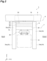
FIG. 2 is a side view illustrating a travelling vehicle according to the first embodiment as viewed from a side. -
FIG. 3 is a rear view of a body of the travelling vehicle inFIG. 1 as viewed from the rear in a travelling direction. -
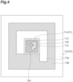
FIG. 4 is a diagram illustrating an example of a color scheme pattern for a large marker and a small marker provided on the body. -
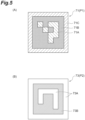
FIG. 5(A) is an example of a color scheme pattern for the small marker andFIG. 5(B) is an example of a color scheme pattern for the large marker. -
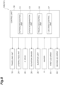
FIG. 6 is a block diagram illustrating a functional configuration of the travelling vehicle inFIG. 1 . -
FIG. 7 is a rear view of a body of a travelling vehicle according to a second embodiment as viewed from the rear in the travelling direction. -
FIG. 8 is a block diagram illustrating a functional configuration of the travelling vehicle according to the second embodiment. - A preferred embodiment according to an aspect of the present invention will be described in detail below with reference to the drawings. In the description of the drawings, identical constituent elements will be denoted by identical reference signs and redundant explanations will be omitted.
- With reference to
FIG. 1 to FIG. 6 mainly, atravelling vehicle system 1 of a first embodiment will be described. Thetravelling vehicle system 1 is a system to transport, by using anoverhead travelling vehicle 6 capable of moving along a track (predetermined travelling path) 4, anarticle 10 betweenplacement sections article 10 include containers such as a front opening unified pod (FOUP) storing a plurality of semiconductor wafers and a reticle pod storing a glass substrate, and common parts. In this case, thetravelling vehicle system 1 in which, for example, the overhead travelling vehicle 6 (hereinafter simply referred to as "travelling vehicle 6") travels along the one-way track 4 that is laid on a ceiling or the like of a factory will be described as an example. As illustrated inFIG. 1 , thetravelling vehicle system 1 includes thetrack 4, a plurality of theplacement sections 9, and a plurality of thetravelling vehicles 6. - As illustrated in
FIG. 2 , thetrack 4 is laid, for example, in the vicinity of the ceiling that is a space above a worker's head. Thetrack 4 is, for example, suspended from the ceiling. - As illustrated in
FIG. 1 andFIG. 2 , theplacement sections 9 are arranged along thetrack 4 and provided at locations where thearticle 10 can be delivered to and from thetravelling vehicle 6. Theplacement sections 9 each include a buffer and a delivery port. The buffer is a placement section on which thearticle 10 is temporarily placed. The buffer is a placement section on which thearticle 10 is temporarily placed when thearticle 10 transported by thetravelling vehicle 6 is unable to be transferred to a target delivery port, for example, for the reason that anotherarticle 10 has been placed on the target delivery port. The delivery port is, for example, a placement section for delivering thearticle 10 to and from a semiconductor processing device (not illustrated) such as a cleaning device, a deposition device, a lithography device, an etching device, a thermal treatment device, and a planarization device. The processing device is not limited to a specific device and may be a variety of devices. - For example, the
placement sections 9 are arranged to a side of thetrack 4. In this case, the travellingvehicle 6 delivers thearticle 10 to and from theplacement section 9, by laterally feeding anelevation driver 28 or the like by alateral feed unit 24 and by elevating and lowering anelevation unit 30. Although not illustrated, theplacement section 9 may be arranged immediately below thetrack 4. In this case, the travellingvehicle 6 elevates and lowers theelevation unit 30 to deliver thearticle 10 to and from theplacement section 9. - As illustrated in
FIG. 2 , the travellingvehicle 6 travels along thetrack 4 and transports thearticle 10. The travellingvehicle 6 is configured so that thearticle 10 can be transferred. The travellingvehicle 6 is an automated overhead transport vehicle. The number of travellingvehicles 6 included in the travellingvehicle system 1 is not particularly limited and is more than one. As illustrated inFIG. 2 andFIG. 3 , the travellingvehicles 6 each includes a travellingunit 18, abody 7, animager 8, amarker 70, and acontrol unit 50. - The travelling
unit 18 includes a motor or the like and causes the travellingvehicle 6 to travel along thetrack 4. Thebody 7 includes abody frame 22, thelateral feed unit 24, aθ drive 26, theelevation driver 28, theelevation unit 30, and abody cover 33. - The
body frame 22 supports thelateral feed unit 24, theθ drive 26, theelevation driver 28, and theelevation unit 30. Thelateral feed unit 24 laterally feeds theθ drive 26, theelevation driver 28, and theelevation unit 30 collectively in a direction perpendicular to the travelling direction of thetrack 4. The θ drive 26 turns at least one of theelevation driver 28 and theelevation unit 30 within a predetermined angle range in a horizontal plane. Theelevation driver 28 elevates and lowers theelevation unit 30 by reeling or unreeling a hanging member such as a wire, rope, or belt. Theelevation unit 30 has a chuck and can freely grip or release thearticle 10. - The body cover 33 is provided at each of the front and the rear of the travelling
vehicle 6. The body cover 33 extends and retracts a not-illustrated claw and prevents thearticle 10 from dropping during transportation. The body cover 33 includes afront cover 34 provided at the front of the travellingvehicle 6 and arear cover 35 provided at the rear of the travellingvehicle 6 in the travelling direction. Thefront cover 34 is formed in a substantially isosceles trapezoidal shape in plan view when viewed from above, and has afront face 34a facing outward (forward), arear face 34b facing inward (rearward) where theelevation unit 30 is provided, and leg faces 34c and 34c connecting thefront face 34a and therear face 34b. Therear cover 35 is formed in a substantially isosceles trapezoidal shape in plan view when viewed from above, and has arear face 35a facing outward (rearward), afront face 35b facing inward (forward) where theelevation unit 30 is provided, and leg faces 35c and 35c connecting therear face 35a andfront face 35b. - The
imager 8 is provided on thefront face 34a of thefront cover 34 of thebody 7 so that the image capturing range is in front of the travellingvehicle 6 that is the subject travelling vehicle. Theimager 8 is a device that includes a lens and an imaging element or the like that converts light entering from the lens into an electrical signal. A captured image acquired by theimager 8 is acquired by thecontrol unit 50 which will be described in detail in a subsequent paragraph. - As illustrated in
FIG. 3 , themarker 70 is provided on therear face 35a of therear cover 35 so as to be visible from other travelling vehicle 6 (hereinafter referred to as "following travellingvehicle 6") located at the rear of thesubject travelling vehicle 6. Themarker 70 includes asmall marker 71 and alarge marker 73, as illustrated inFIG. 4 . Thelarge marker 73 has a larger surface area than that of thesmall marker 71, and a display pattern VP2 includes afirst region 73A, asecond region 73B with lower reflectance than that of thefirst region 73A, and aregion 73C where thesmall marker 71 is arranged. - The
small marker 71 is arranged on theregion 73C inside the region where thelarge marker 73 is configured. The center (center of gravity) position of the region that constitutes thesmall marker 71 may coincide with the center (center of gravity) position of the region that constitutes thelarge marker 73. A display pattern VP1 includes athird region 71A with a lower reflectance than that of thefirst region 73A, afourth region 71B with a lower reflectance than that of thethird region 71A and that of thesecond region 73B, and afifth region 71C that encompasses thethird region 71A and thefourth region 71B and has a lower reflectance than that of thefirst region 73A of thelarge marker 73 and a higher reflectance that of than thefourth region 71B. - The reflectance in the present embodiment is the reflectance when visible light is used for irradiation, and the relation between the reflectances of the regions is "the
first region 73A > thethird region 71A and thefifth region 71C > thesecond region 73B > thefourth region 71B". In the present embodiment, thethird region 71A and thefifth regions 71C of thesmall marker 71 are formed in light gray and thefourth region 71B in black, while thefirst region 73A of thelarge marker 73 is formed in white and thesecond region 73B in dark gray. In other words, the relation between the brightnesses of the regions is configured so that "thefirst region 73A > thethird region 71A and thefifth region 71C > thesecond region 73B > thefourth region 71B", resulting in the above relation of reflectances. - Here, brightness is used as an example of a factor that determines reflectance to visible light, but it can also be color density, saturation, and the like. It may also be the reflectances of the
small marker 71 and thelarge marker 73 to infrared light. Again, the reflectances of the regions in thesmall marker 71 and thelarge marker 73 have the relation described above. - The
large marker 73 is formed in a size that does not entirely fit within the image capturing range of theimager 8 equipped in the following travelling vehicle (the other travelling vehicle) 6 located at a position at which a distance from thesubject travelling vehicle 6 is less than a predetermined distance (for example, 0.5 m). Thesmall marker 71 is formed in a size that entirely fits within the image capturing range of theimager 8 equipped in the following travellingvehicle 6 even if the distance from thesubject travelling vehicle 6 is less than the predetermined distance (for example, 0.5 m). - In this case, "the
small marker 71 entirely fits within the image capturing range" includes not only the case of being captured in a size that is extracted (recognized) by apattern recognition unit 51 which will be described in detail in a subsequent paragraph but also the case of being captured in a size that is not extracted (recognized) by thepattern recognition unit 51. That is, the position where thesmall marker 71 is placed only needs to be equipped in the image capturing range. In addition, it does not matter whether theimager 8 is in focus. Moreover, "even if the distance is less than the above-described predetermined distance" in this case may be the case where the distance at which the travellingvehicles - The
small marker 71 and thelarge marker 73 may be directly drawn on therear cover 35, or a plate or the like on which thesmall marker 71 and thelarge marker 73 are drawn may be fixed to therear cover 35. The images of thesmall marker 71 and thelarge marker 73 may be displayed on a display unit such as a liquid crystal display provided on therear cover 35. - The
control unit 50 is an electronic control unit including a central processing unit (CPU), a read only memory (ROM), and a random access memory (RAM). Thecontrol unit 50 controls various operations in the travellingvehicle 6. Specifically, as illustrated inFIG. 6 , thecontrol unit 50 controls the travellingunit 18, thelateral feed unit 24, theθ drive 26, theelevation driver 28, theelevation unit 30, and theimager 8. Thecontrol unit 50 can be configured, for example, as software that is a program stored in the ROM, loaded into the RAM, and executed by the CPU. Thecontrol unit 50 may be configured as hardware with electronic circuitry, for example. In thecontrol unit 50, as the hardware such as the CPU, the RAM, and the ROM, and the software such as the program collaborate, thepattern recognition unit 51, astate determination unit 53, and a travellingcontrol unit 55 as described below are formed. Thecontrol unit 50 communicates with acontroller 60 using a communication line (feeder line) of thetrack 4. - The
pattern recognition unit 51 attempts to recognize (extract) themarker 70 from a captured image acquired by theimager 8. Thepattern recognition unit 51 recognizes thesmall marker 71 based on a first image in which thesmall marker 71 is entirely equipped in the image capturing range of theimager 8 and thelarge marker 73 is not entirely equipped in the image capturing range, and also recognizes thelarge marker 73 based on a second image in which thesmall marker 71 and thelarge marker 73 are entirely equipped in the image capturing range. More specifically, thepattern recognition unit 51 recognizes thesmall marker 71 by recognizing a first color scheme pattern P1 illustrated inFIG. 5(A) , which is obtained by binarizing thesmall marker 71 in the first image so that the region corresponding to thethird region 71A is white and the region corresponding to thefourth region 71B is black. Thepattern recognition unit 51 also recognizes thelarge marker 73 by recognizing a second color scheme pattern P2 illustrated inFIG. 5(B) , which is obtained by binarizing thelarge marker 73 in the second image so that the region corresponding to thefirst region 73A is white and the regions corresponding to thesecond region 73B and the region of thesmall marker 71 are black. - Based on the recognition of the
small marker 71 or thelarge marker 73 by thepattern recognition unit 51, thestate determination unit 53 determines whether another travelling vehicle 6 (hereinafter referred to as "preceding travellingvehicle 6") located at the front of thesubject travelling vehicle 6 is present. Thestate determination unit 53 determines that the preceding travellingvehicle 6 is present when at least one of the entiresmall marker 71 and the entirelarge marker 73 is extracted from a captured image. When thesmall marker 71 is recognized by thepattern recognition unit 51, thestate determination unit 53 in the present embodiment determines that the distance from thesubject travelling vehicle 6 to the preceding travellingvehicle 6 is smaller than that when thelarge marker 73 is recognized. More specifically, thestate determination unit 53 determines that the distance from thesubject travelling vehicle 6 to the preceding travellingvehicle 6 is less than 0.5 m when thepattern recognition unit 51 recognizes thesmall marker 71, and the distance from thesubject travelling vehicle 6 to the preceding travellingvehicle 6 is 0.5 m or more when thelarge marker 73 is recognized. - When the
large marker 73 is recognized by thepattern recognition unit 51, the travellingcontrol unit 55 controls the travellingunit 18 to travel at a speed slower than a normal moving speed, for example. When thesmall marker 71 is recognized by thepattern recognition unit 51, the travellingcontrol unit 55 controls the travellingunit 18 to come to a complete stop. This control is an example, and the control performed when thesmall marker 71 or thelarge marker 73 is distinctively recognized by thepattern recognition unit 51 is not limited to the above control. - The
controller 60 is an electronic control unit including a CPU, a ROM, a RAM, and the like. Thecontroller 60 can be configured, for example, as software that is a program stored in the ROM, loaded into the RAM, and executed by the CPU. Thecontroller 60 may be configured as hardware with electronic circuitry, for example. Thecontroller 60 transmits a transportation command to the travellingvehicle 6 to transport thearticle 10. - Next, the operation and effect of the travelling
vehicle system 1 of the above-described first embodiment will be described. In the travellingvehicle system 1 of the above-described first embodiment, even when the inter-vehicle distance between two of the travellingvehicles pattern recognition unit 51 can recognize thesmall marker 71 because thesmall marker 71 is captured by theimager 8. In the travellingvehicle system 1 of the above-described first embodiment, when the inter-vehicle distance between the two travellingvehicles small marker 71 and thelarge marker 73 are captured by theimager 8, but the display pattern VP2 is employed in which thethird region 71A of thesmall marker 71 has a lower reflectance than that of thefirst region 73A of thelarge marker 73 and thefourth region 71B of thesmall marker 71 has a lower reflectance than that of thesecond region 73B of thelarge marker 73, thepattern recognition unit 51 can easily recognize the entiresmall marker 71 as thesecond region 73B of thelarge marker 73. This allows thepattern recognition unit 51 to more reliably recognize thelarge marker 73 from a captured image in which thesmall marker 71 andlarge marker 73 are captured. In other words, for a captured image in which both thesmall marker 71 and thelarge marker 73 are captured, although thesmall marker 71 is difficult to be recognized as a single marker, thepattern recognition unit 51 recognizes elements of thesmall marker 71 as part of thelarge marker 73, making it easier to recognize thelarge marker 73. As a result, the travellingvehicle 6 can more reliably recognize the preceding travellingvehicle 6 regardless of the inter-vehicle distance between the two travellingvehicles - In the travelling
vehicle system 1 of the above-described first embodiment, thesmall marker 71 has thethird region 71A and thefourth region 71B arranged inside thefifth region 71C that is formed as a frame, and thefifth region 71C has a lower reflectance than that of thefirst region 73A of thelarge marker 73 and a higher reflectance than that of thefourth region 71B of thesmall marker 71. This allows thepattern recognition unit 51 to more reliably recognize thelarge marker 73 from a captured image in which thesmall marker 71 and thelarge marker 73 are captured. - In the travelling
vehicle system 1 of the above-described first embodiment, thepattern recognition unit 51 recognizes thesmall marker 71 by recognizing the first color scheme pattern P1 (refer toFIG. 5(A) ), which is obtained by binarizing thesmall marker 71 so that the region corresponding to thethird region 71A is white and the region corresponding to thefourth region 71B is black. Thepattern recognition unit 51 also recognizes thelarge marker 73 by recognizing the second color scheme pattern P2 (refer toFIG. 5(B) ), which is obtained by binarizing thelarge marker 73 so that the region corresponding to thefirst region 73A of thelarge marker 73 is white and the regions corresponding to thesecond region 73B and the region of thesmall marker 71 are black. This allows thepattern recognition unit 51 to recognize thesmall marker 71 andlarge marker 73 from a captured image using a simple processing method. - In the travelling
vehicle system 1 of the above-described first embodiment, the color scheme of the display pattern VP2 of thelarge marker 73 and the color scheme of the display pattern VP1 of thesmall marker 71 are different from each other. When thesmall marker 71 is recognized by thepattern recognition unit 51, thestate determination unit 53 determines that the distance from thesubject travelling vehicle 6 to the preceding travellingvehicle 6 is smaller than that when thelarge marker 73 is recognized. This allows detection of the distance to a travellingvehicle 6 located at the front or the rear without deploying a sensor or another device. - With reference to
FIG. 7 to FIG. 8 mainly, a travellingvehicle system 101 of a second embodiment will be described. The travellingvehicle system 101 of the second embodiment is provided with a first LED array (first display unit) 81, a second LED array (second display unit) 83, and an LEDarray control unit 57 in addition to the configuration of the travellingvehicle system 1 of the first embodiment. Thefirst LED array 81, thesecond LED array 83, and the LEDarray control unit 57 are described in detail here. - As illustrated in
FIG. 7 , thefirst LED array 81 and thesecond LED array 83 are arranged on therear cover 35 of a travellingvehicle 106. Thefirst LED array 81 is arranged such that it entirely fits within the image capturing range of theimager 8 equipped in a preceding travellingvehicle 106 even if the distance from asubject travelling vehicle 106 is less than a predetermined distance (for example, 0.5 m). Thesecond LED array 83 is arranged such that it does not entirely fit within the image capturing range of theimager 8 equipped in the preceding travellingvehicle 106 locate at a position at which the distance from thesubject travelling vehicle 106 is less than a predetermined distance (for example, 0.5 m). Thefirst LED array 81 and thesecond LED array 83 may be arranged on thefront cover 34 of the travellingvehicle 106. - The
first LED array 81 is an LED unit having an array of a plurality of (six)LEDs second LED array 83 is an LED unit having an array of a plurality of (six)LEDs first LED array 81 and thesecond LED array 83 switch a display manner according to a state of the subject travelling vehicle 106 (the travellingvehicle 106 provided with thefirst LED array 81 and the second LED array 83). - Specifically, the
first LED array 81 changes a display manner with a combination of anilluminated LED 81A and a not-illuminatedLED 81A among fiveLEDs 81A (hereinafter simply referred to as "combination of illumination"). OneLED 81B that remains is used as a parity. That is, theLED 81B is used to determine whether a combination of illumination of fiveLEDs 81A is the display manner intended by thecontrol unit 50. The switching of display manners in thefirst LED array 81 is performed by thecontrol unit 50. Similarly to thefirst LED array 81, thesecond LED array 83 changes a display manner with a combination of anilluminated LED 83A and a not-illuminatedLED 83A among fiveLEDs 83A. OneLED 83B that remains is used as a parity, which is also similar to thefirst LED array 81. - In the
control unit 50, in addition to forming thepattern recognition unit 51, thestate determination unit 53, and the travellingcontrol unit 55 as described above, the LEDarray control unit 57 is formed. The LEDarray control unit 57 switches display manners of thefirst LED array 81 and thesecond LED array 83 according to a travelling state of thesubject travelling vehicle 106. Specifically, for example, when the LEDarray control unit 57 receives a command from thecontroller 60 and acquires that the travelling state of the subject travelling vehicle becomes an acceleration state or a deceleration state, the LEDarray control unit 57 controls illumination of theLEDs 81A in thefirst LED array 81 and illumination of theLEDs 83A in thesecond LED array 83 to attain a display manner corresponding to the acquired travelling state. In other words, the LEDarray control unit 57 transmits the travelling state of thesubject travelling vehicle 106 to a travellingvehicle 106 located at the rear of thesubject travelling vehicle 106 by switching display manners of thefirst LED array 81 and thesecond LED array 83 provided on the travellingvehicle 106. - For example, the following describes the operation of the following travelling
vehicle 106 when the preceding travellingvehicle 106 decelerates. For example, in a case where the preceding travellingvehicle 106 detects an obstacle ahead with an obstacle sensor or the like, the preceding travellingvehicle 106 decelerates when the distance to the obstacle ahead is a predetermined distance and stops when the distance to the obstacle ahead is a second predetermined distance shorter than the previous predetermined distance. The preceding travellingvehicle 106 decelerates when the distance to the obstacle ahead is the predetermined distance and simultaneously indicates that the state of the subject travelling vehicle is the decelerated state with thefirst LED array 81 and thesecond LED array 83. - The travelling
control unit 55 of the following travellingvehicle 106 determines the state of the preceding travellingvehicle 106 based on the combination of illumination of thefirst LED array 81 and thesecond LED array 83 that are captured by theimager 8. At the same time, thepattern recognition unit 51 of the following travellingvehicle 106 attempts to recognize thesmall marker 71 and thelarge marker 73 based on an image captured by theimager 8. Here, if thepattern recognition unit 51 recognizes thesmall marker 71, the preceding travellingvehicle 106 is determined to be less than 0.5 m ahead of the following travellingvehicle 106, and the travellingcontrol unit 55 stops the travellingunit 18. If thepattern recognition unit 51 recognizes thelarge marker 73, the preceding travellingvehicle 106 is determined to be at least 0.5 m ahead of the following travellingvehicle 106, and the travellingcontrol unit 55 decelerates the travellingunit 18. - For example, the following describes the operation of the following travelling
vehicle 106 when the preceding travellingvehicle 106 accelerates. For example, when the preceding travellingvehicle 106 accelerates forward by receiving a transport command from thecontroller 60, or the like, it displays on thefirst LED array 81 and thesecond LED array 83 that the state of the subject travelling vehicle is in the accelerated state. The travellingcontrol unit 55 of the following travellingvehicle 106 determines the state of the preceding travellingvehicle 106 based on the combination of illumination of thefirst LED array 81 and thesecond LED array 83 that are captured by theimager 8. At the same time, thepattern recognition unit 51 of the following travellingvehicle 106 attempts to recognize thesmall marker 71 and thelarge marker 73 based on an image captured by theimager 8. Here, if thepattern recognition unit 51 recognizes thelarge marker 73, the preceding travellingvehicle 106 is determined to be at least 0.5 m ahead of the following travellingvehicle 106, and the travellingcontrol unit 55 accelerates the travellingunit 18. This allows the following travellingvehicle 106 to smoothly follow the preceding travellingvehicle 106. On the other hand, if thepattern recognition unit 51 recognizes thesmall marker 71, the preceding travellingvehicle 106 is determined to be less than 0.5 m ahead of the following travellingvehicle 106, and immediate following of the preceding travelling vehicle is avoided and the current travelling state is maintained. This reduces the likelihood that the following travellingvehicle 106 will collide with the preceding travellingvehicle 106. - The operation and effect of the travelling
vehicle system 101 in the above-described second embodiment will be described. In the travellingvehicle system 101 of the above-described second embodiment, since a display manner that varies according to a state of the travellingvehicle 106 is displayed on thefirst LED array 81 and thesecond LED array 83, the following travellingvehicle 106 that has acquired the display manners of thefirst LED array 81 and thesecond LED array 83 with theimager 8 can determine the state of the preceding travellingvehicle 106 instantaneously. With this configuration, the following travellingvehicle 106 can promptly perform operation appropriate for the state of the preceding travellingvehicle 106. In the travellingvehicle system 101 of the above-described second embodiment, thefirst LED array 81 is arranged corresponding to thesmall marker 71 and thesecond LED array 83 is provided corresponding to thelarge marker 73, so that even if the inter-vehicle distance between the two travellingvehicles imager 8 captures at least one of thefirst LED array 81 and thesecond LED array 83. This allows the following travellingvehicle 106 to more reliably acquire information on the preceding travellingvehicle 106 regardless of the inter-vehicle distance between the two travellingvehicles - In the travelling
vehicle system 101 of the above-described second embodiment, thefirst LED array 81 and thesecond LED array 83 switch their display manners according to the travelling state of thesubject travelling vehicle 106, and the travelling state includes an acceleration state and a deceleration state. This configuration enables the following travellingvehicle 106 to grasp at least whether the preceding travellingvehicle 106 is in the accelerated state or the decelerated state. - Although an embodiment has been described above, an aspect of the present invention is not limited to the above-described embodiment. Various modifications can be made without departing from the gist of the invention.
- In the travelling
vehicle 6 and the travellingvehicle system 1 of the above-described first embodiment, an example has been described in which theimager 8 is provided, theimager 8 including: a lens; and an imaging element or the like that converts light entering from the lens into an electrical signal, theimager 8 having no function of measuring the distance to and from a target object, but the embodiment is not limited thereto. As theimager 8, a device having a distance measuring function such as a stereo camera, a TOF camera, and the like may be applied. - The travelling vehicle 6 (106) and the travelling
vehicle system 1 of the above-described embodiments and modifications have been described with an example in which thesmall marker 71 andlarge marker 73 are formed as display patterns consisting of shapes in a plurality of colors (for example, AR markers), but they may also be, for example, two-dimensional codes. Examples of the two-dimensional code include a QR code (registered trademark), for example. The above-described embodiments and modifications have been described with an example in which the display patterns of thesmall marker 71 and thelarge marker 73 are different from each other, but the display patterns may be the same for each other. - The above-described embodiments and modifications have been described with an example in which the
control unit 50 that controls the travelling vehicle 6 (106) is provided in thebody 7 of the individual travelling vehicle 6 (106), but thecontrol unit 50 may be separated from thebody 7 and placed at a position where thecontrol unit 50 can perform communication by wire or wirelessly (for example, the controller 60). In such a case, thecontrol unit 50 may be configured to collectively control a plurality of travelling vehicles 6 (106) instead of being provided for each of the travellingvehicles 6. - The travelling vehicle 6 (106) and the travelling
vehicle system 1 of the above-described embodiments and modifications have been described with an overhead travelling vehicle as one example of the travelling vehicle, but other examples of the travelling vehicle include an unmanned vehicle, a stacker crane, and the like that travel on a track laid out on the ground or a frame. - The travelling vehicle 6 (106) and the travelling
vehicle system 1 of the above-described embodiments and modifications have been described with an example in which thesmall marker 71 and thelarge marker 73 are provided on therear face 35a of therear cover 35, but the position at which the markers are provided is not limited as long as it is a position visible from other travelling vehicle 6 (106). For example, thesmall marker 71 and thelarge marker 73 may be provided on the leg faces 35c and 35c instead of or in addition to therear face 35a. Furthermore, the above-described embodiments and modifications have been described with an example in which thesmall marker 71 and thelarge marker 73 are arranged at a position on the preceding travellingvehicle 6, the position being visible from the following travelling vehicle 6 (i.e., therear face 35a of the preceding travelling vehicle 6), but thesmall marker 71 andlarge marker 73 may be arranged at a position on the following travellingvehicle 6, the position visible from the preceding travelling vehicle 6 (e.g., thefront face 34a, the leg faces 34c and 34c, and the like of the following travelling vehicle 6). - The travelling vehicle 6 (106) and the travelling
vehicle system 1 of the above-described embodiments and modifications have been described with an example in which thefirst LED array 81 and thesecond LED array 83 are employed as the first display unit and the second display unit that switch a display manner according to the state of the subject travelling vehicle. However, the present invention is not limited thereto. For example, a liquid crystal display screen may be employed, and display contents (color, pattern, symbol, character, etc.) may be changed according to the state of the subject travelling vehicle. Alternatively, an illumination device that simply switches colors to be displayed (emitted) may be employed. - The travelling vehicle 6 (106) and the travelling
vehicle system 1 of the above-described embodiments and modifications have been described with an example in which the acceleration state and the deceleration state are described as examples of the state of the subject travelling vehicle, but it could be, for example, the current position of the subject travelling vehicle, or information such as whether anarticle 10 is being conveyed. -
- 1, 101
- travelling vehicle system
- 6, 106
- overhead travelling vehicle (travelling vehicle)
- 7
- body
- 8
- imager
- 33
- body cover
- 34
- front cover
- 35
- rear cover
- 50
- control unit
- 51
- pattern recognition unit
- 53
- state determination unit
- 55
- travelling control unit
- 57
- LED array control unit
- 70
- marker
- 71
- small marker
- 71A
- third region
- 71B
- fourth region
- 71C
- fifth region
- 73
- large marker
- 73A
- first region
- 73B
- second region
- 81
- first LED array (first display unit)
- 83
- second LED array (second display unit)
- P1
- first color scheme pattern
- P2
- second color scheme pattern
Claims (7)
- A travelling vehicle configured to travel along a predetermined travelling path, the travelling vehicle comprising:a body provided with a small marker and a large marker having a larger surface area than a surface area of the small marker;at least one imager provided on the body such that an image capturing range of the imager is at least one of a front and a rear of the travelling vehicle that is a subject travelling vehicle;a pattern recognition unit configured to distinctively recognize the small marker and the large marker based on a captured image acquired by the imager; anda state determination unit configured to determine that the travelling vehicle that is another travelling vehicle is present in at least one of the front and the rear of the subject travelling vehicle when the small marker or the large marker is recognized by the pattern recognition unit, whereinthe large marker is configured to be of a size that does not entirely fit within the image capturing range of the imager equipped in the other travelling vehicle that is located less than a predetermined distance from the subject travelling vehicle,the small marker is configured to be of a size that entirely fits within the image capturing range of the imager equipped in the other travelling vehicle when a distance from the subject travelling vehicle is less than the predetermined distance from the subject travelling vehicle, the small marker being arranged inside a region where the large marker is configured,the large marker has a display pattern including a first region, a second region with a lower reflectance than a reflectance of the first region and a region where the small marker is arranged, andthe small marker has a display pattern including a third region with a lower reflectance than the reflectance of the first region and a fourth region with a lower reflectance than the reflectance of the third region and a lower reflectance than the reflectance of the second region.
- The travelling vehicle according to claim 1, whereinthe small marker has the third region and the fourth region arranged inside a fifth region that is formed as a frame, andthe fifth region has a lower reflectance than the reflectance of the first region of the large marker and a higher reflectance than the reflectance of the fourth region of the small marker.
- The travelling vehicle according to claim 1 or 2, wherein
the pattern recognition unit recognizes the small marker by recognizing a first color scheme pattern obtained by binarizing the small marker so that a region corresponding to the third region is white and a region corresponding to the fourth region is black, and recognizes the large marker by recognizing a second color scheme pattern obtained by binarizing the large marker so that a region corresponding to the first region is white and regions corresponding to the second region and the regions of the small marker are black. - The travelling vehicle according to any one of claims 1 to 3, whereinthe large marker and the small marker have different display patterns from each other, andthe state determination unit determines that a distance from the subject travelling vehicle to the other travelling vehicle is smaller when the small marker is recognized by the pattern recognition unit compared to when the large marker is recognized.
- The travelling vehicle according to any one of claims 1 to 4, whereinthe body is further provided with a first display unit arranged to not entirely fit within the image capturing range of the imager equipped in the other travelling vehicle that is located less than the predetermined distance from the subject travelling vehicle, the first display unit being configured to switch a display mode in accordance with a state of the subject travelling vehicle, and a second display unit arranged to entirely fit within the image capturing range of the imager equipped in the other travelling vehicle when a distance from the subject travelling vehicle is less than the predetermined distance from the subject travelling vehicle, the second display unit being configured to switch a display mode in accordance with a state of the subject travelling vehicle,the travelling vehicle further comprising:a travelling unit configured to cause the body to travel along the travelling path; anda travelling control unit configured to acquire a state of the other travelling vehicle based on the display mode of at least one of the first display unit and the second display unit captured by the imager and control the subject travelling unit based on the state that has been acquired.
- The travelling vehicle according to claim 5, whereinthe first display unit and the second display unit each switch the display mode according to a travelling state of the subject travelling vehicle, andthe travelling state includes an accelerated state and a decelerated state.
- A travelling vehicle system comprising:a plurality of the travelling vehicles according to any one of claims 1 to 6;a track along which the travelling vehicles travel in a predetermined direction; and
a travelling vehicle controller configured to assign a transportation command to the travelling vehicles.
Applications Claiming Priority (2)
| Application Number | Priority Date | Filing Date | Title |
|---|---|---|---|
| JP2021034599 | 2021-03-04 | ||
| PCT/JP2022/002699 WO2022185787A1 (en) | 2021-03-04 | 2022-01-25 | Travelling vehicle and travelling vehicle system |
Publications (3)
| Publication Number | Publication Date |
|---|---|
| EP4300243A1 true EP4300243A1 (en) | 2024-01-03 |
| EP4300243A4 EP4300243A4 (en) | 2025-03-26 |
| EP4300243B1 EP4300243B1 (en) | 2026-02-25 |
Family
ID=83154951
Family Applications (1)
| Application Number | Title | Priority Date | Filing Date |
|---|---|---|---|
| EP22762846.8A Active EP4300243B1 (en) | 2021-03-04 | 2022-01-25 | Travelling vehicle and travelling vehicle system |
Country Status (8)
| Country | Link |
|---|---|
| US (1) | US12286144B2 (en) |
| EP (1) | EP4300243B1 (en) |
| JP (1) | JP7396532B2 (en) |
| KR (1) | KR102797015B1 (en) |
| CN (1) | CN116888553B (en) |
| IL (1) | IL305367B1 (en) |
| TW (1) | TWI870650B (en) |
| WO (1) | WO2022185787A1 (en) |
Families Citing this family (1)
| Publication number | Priority date | Publication date | Assignee | Title |
|---|---|---|---|---|
| WO2024150503A1 (en) * | 2023-01-12 | 2024-07-18 | 村田機械株式会社 | Traveling vehicle and traveling vehicle system |
Family Cites Families (22)
| Publication number | Priority date | Publication date | Assignee | Title |
|---|---|---|---|---|
| US7343660B1 (en) * | 1954-07-28 | 2008-03-18 | Lemeison Medical, Education & Research Foundation, Limited Partnership | Machine tool system |
| JP3928871B2 (en) * | 1996-09-30 | 2007-06-13 | ソニー株式会社 | Identification apparatus and method |
| JPH10160835A (en) * | 1996-11-29 | 1998-06-19 | Sumitomo Electric Ind Ltd | Leading vehicle recognition method |
| JPH11202940A (en) | 1998-01-19 | 1999-07-30 | Murata Mach Ltd | Automatic guided vehicle |
| JP4254588B2 (en) * | 2004-03-18 | 2009-04-15 | 沖電気工業株式会社 | Autonomous robot and control method thereof |
| JP2007104019A (en) * | 2005-09-30 | 2007-04-19 | Matsushita Electric Ind Co Ltd | In-vehicle device |
| KR20110107593A (en) | 2010-03-25 | 2011-10-04 | 삼성전기주식회사 | Firing furnace for ceramic products and firing method using the same |
| US9791865B2 (en) * | 2014-10-29 | 2017-10-17 | Amazon Technologies, Inc. | Multi-scale fiducials |
| KR102204735B1 (en) * | 2016-08-22 | 2021-01-19 | 무라다기카이가부시끼가이샤 | Driving vehicle system and control method of driving vehicle system |
| JP2020024476A (en) * | 2016-12-14 | 2020-02-13 | 村田機械株式会社 | Traveling vehicle system |
| JP6771588B2 (en) * | 2017-08-07 | 2020-10-21 | パナソニック株式会社 | Moving body and control method of moving body |
| WO2019053798A1 (en) * | 2017-09-13 | 2019-03-21 | 株式会社Doog | Autonomous traveling robot system |
| JP7013212B2 (en) | 2017-11-14 | 2022-01-31 | Tvs Regza株式会社 | Electronic devices, markers, control methods and programs for electronic devices |
| JP2019102047A (en) * | 2017-11-28 | 2019-06-24 | Thk株式会社 | Image processor, mobile robot control system, and mobile robot control method |
| US11866197B2 (en) * | 2018-03-13 | 2024-01-09 | Nec Corporation | Target member |
| JP2019179496A (en) * | 2018-03-30 | 2019-10-17 | 日本電産シンポ株式会社 | Computer system and computer program |
| US11184967B2 (en) * | 2018-05-07 | 2021-11-23 | Zane Coleman | Angularly varying light emitting device with an imager |
| JP2020131943A (en) * | 2019-02-20 | 2020-08-31 | 住友電気工業株式会社 | Parking control systems, in-vehicle devices, parking control methods, and computer programs |
| US10940796B2 (en) * | 2019-04-05 | 2021-03-09 | Ford Global Technologies, Llc | Intent communication for automated guided vehicles |
| JP7310889B2 (en) * | 2019-07-17 | 2023-07-19 | 村田機械株式会社 | Running vehicle, running vehicle system, and running vehicle detection method |
| KR20210127267A (en) * | 2020-04-13 | 2021-10-22 | 현대자동차주식회사 | Vehicle and method for controlling thereof |
| US12505557B2 (en) * | 2022-04-28 | 2025-12-23 | Universal City Studios Llc | Systems and methods for providing a show effect using a detectable marker |
-
2022
- 2022-01-25 EP EP22762846.8A patent/EP4300243B1/en active Active
- 2022-01-25 IL IL305367A patent/IL305367B1/en unknown
- 2022-01-25 KR KR1020237028406A patent/KR102797015B1/en active Active
- 2022-01-25 CN CN202280016628.3A patent/CN116888553B/en active Active
- 2022-01-25 WO PCT/JP2022/002699 patent/WO2022185787A1/en not_active Ceased
- 2022-01-25 JP JP2023503632A patent/JP7396532B2/en active Active
- 2022-01-25 US US18/278,456 patent/US12286144B2/en active Active
- 2022-03-02 TW TW111107504A patent/TWI870650B/en active
Also Published As
| Publication number | Publication date |
|---|---|
| JPWO2022185787A1 (en) | 2022-09-09 |
| EP4300243B1 (en) | 2026-02-25 |
| EP4300243A4 (en) | 2025-03-26 |
| KR102797015B1 (en) | 2025-04-21 |
| US20240227881A9 (en) | 2024-07-11 |
| US12286144B2 (en) | 2025-04-29 |
| TWI870650B (en) | 2025-01-21 |
| US20240132123A1 (en) | 2024-04-25 |
| JP7396532B2 (en) | 2023-12-12 |
| IL305367B1 (en) | 2026-02-01 |
| CN116888553A (en) | 2023-10-13 |
| IL305367A (en) | 2023-10-01 |
| WO2022185787A1 (en) | 2022-09-09 |
| KR20230136151A (en) | 2023-09-26 |
| CN116888553B (en) | 2026-04-24 |
| TW202240127A (en) | 2022-10-16 |
Similar Documents
| Publication | Publication Date | Title |
|---|---|---|
| US11904887B2 (en) | Traveling vehicle and traveling vehicle system | |
| US12588468B2 (en) | Overhead transport vehicle | |
| EP4300243B1 (en) | Travelling vehicle and travelling vehicle system | |
| US11027927B2 (en) | Article conveyance apparatus | |
| JP7310889B2 (en) | Running vehicle, running vehicle system, and running vehicle detection method | |
| EP4336299B1 (en) | Traveling vehicle and traveling vehicle system | |
| JP7501557B2 (en) | Vehicle System | |
| TWI913509B (en) | Walking vehicle system and walking vehicle | |
| TW202428498A (en) | Traveling vehicle and traveling vehicle system |
Legal Events
| Date | Code | Title | Description |
|---|---|---|---|
| STAA | Information on the status of an ep patent application or granted ep patent |
Free format text: STATUS: THE INTERNATIONAL PUBLICATION HAS BEEN MADE |
|
| PUAI | Public reference made under article 153(3) epc to a published international application that has entered the european phase |
Free format text: ORIGINAL CODE: 0009012 |
|
| STAA | Information on the status of an ep patent application or granted ep patent |
Free format text: STATUS: REQUEST FOR EXAMINATION WAS MADE |
|
| 17P | Request for examination filed |
Effective date: 20230927 |
|
| AK | Designated contracting states |
Kind code of ref document: A1 Designated state(s): AL AT BE BG CH CY CZ DE DK EE ES FI FR GB GR HR HU IE IS IT LI LT LU LV MC MK MT NL NO PL PT RO RS SE SI SK SM TR |
|
| DAV | Request for validation of the european patent (deleted) | ||
| DAX | Request for extension of the european patent (deleted) | ||
| REG | Reference to a national code |
Ref country code: DE Ref legal event code: R079 Free format text: PREVIOUS MAIN CLASS: G05D0001020000 Ipc: G06V0010200000 Ref country code: DE Ref legal event code: R079 Ref document number: 602022031177 Country of ref document: DE Free format text: PREVIOUS MAIN CLASS: G05D0001020000 Ipc: G06V0010200000 |
|
| A4 | Supplementary search report drawn up and despatched |
Effective date: 20250224 |
|
| RIC1 | Information provided on ipc code assigned before grant |
Ipc: G06V 20/58 20220101ALI20250218BHEP Ipc: H01L 21/677 20060101ALI20250218BHEP Ipc: H01L 21/67 20060101ALI20250218BHEP Ipc: G06V 10/20 20220101AFI20250218BHEP |
|
| GRAP | Despatch of communication of intention to grant a patent |
Free format text: ORIGINAL CODE: EPIDOSNIGR1 |
|
| STAA | Information on the status of an ep patent application or granted ep patent |
Free format text: STATUS: GRANT OF PATENT IS INTENDED |
|
| INTG | Intention to grant announced |
Effective date: 20251105 |
|
| RIN1 | Information on inventor provided before grant (corrected) |
Inventor name: SHIMIZU, YUJI Inventor name: YAMAGAMI, SEIJI |
|
| GRAS | Grant fee paid |
Free format text: ORIGINAL CODE: EPIDOSNIGR3 |
|
| GRAA | (expected) grant |
Free format text: ORIGINAL CODE: 0009210 |
|
| STAA | Information on the status of an ep patent application or granted ep patent |
Free format text: STATUS: THE PATENT HAS BEEN GRANTED |
|
| AK | Designated contracting states |
Kind code of ref document: B1 Designated state(s): AL AT BE BG CH CY CZ DE DK EE ES FI FR GB GR HR HU IE IS IT LI LT LU LV MC MK MT NL NO PL PT RO RS SE SI SK SM TR |
|
| REG | Reference to a national code |
Ref country code: CH Ref legal event code: F10 Free format text: ST27 STATUS EVENT CODE: U-0-0-F10-F00 (AS PROVIDED BY THE NATIONAL OFFICE) Effective date: 20260225 Ref country code: GB Ref legal event code: FG4D |
|
| REG | Reference to a national code |
Ref country code: DE Ref legal event code: R096 Ref document number: 602022031177 Country of ref document: DE |
|
| REG | Reference to a national code |
Ref country code: IE Ref legal event code: FG4D |