EP4300217A1 - Electrode terminal, module, and watch - Google Patents
Electrode terminal, module, and watch Download PDFInfo
- Publication number
- EP4300217A1 EP4300217A1 EP22759303.5A EP22759303A EP4300217A1 EP 4300217 A1 EP4300217 A1 EP 4300217A1 EP 22759303 A EP22759303 A EP 22759303A EP 4300217 A1 EP4300217 A1 EP 4300217A1
- Authority
- EP
- European Patent Office
- Prior art keywords
- section
- battery
- contact
- circuit board
- housing
- Prior art date
- Legal status (The legal status is an assumption and is not a legal conclusion. Google has not performed a legal analysis and makes no representation as to the accuracy of the status listed.)
- Pending
Links
Images


Classifications
-
- G—PHYSICS
- G04—HOROLOGY
- G04G—ELECTRONIC TIME-PIECES
- G04G17/00—Structural details; Housings
-
- G—PHYSICS
- G04—HOROLOGY
- G04G—ELECTRONIC TIME-PIECES
- G04G17/00—Structural details; Housings
- G04G17/02—Component assemblies
- G04G17/06—Electric connectors, e.g. conductive elastomers
-
- G—PHYSICS
- G04—HOROLOGY
- G04C—ELECTROMECHANICAL CLOCKS OR WATCHES
- G04C10/00—Arrangements of electric power supplies in time-pieces
-
- G—PHYSICS
- G04—HOROLOGY
- G04C—ELECTROMECHANICAL CLOCKS OR WATCHES
- G04C3/00—Electromechanical clocks or watches independent of other time-pieces and in which the movement is maintained by electric means
- G04C3/008—Mounting, assembling of components
-
- G—PHYSICS
- G04—HOROLOGY
- G04G—ELECTRONIC TIME-PIECES
- G04G17/00—Structural details; Housings
- G04G17/02—Component assemblies
-
- G—PHYSICS
- G04—HOROLOGY
- G04G—ELECTRONIC TIME-PIECES
- G04G17/00—Structural details; Housings
- G04G17/02—Component assemblies
- G04G17/04—Mounting of electronic components
-
- H—ELECTRICITY
- H01—ELECTRIC ELEMENTS
- H01M—PROCESSES OR MEANS, e.g. BATTERIES, FOR THE DIRECT CONVERSION OF CHEMICAL ENERGY INTO ELECTRICAL ENERGY
- H01M50/00—Constructional details or processes of manufacture of the non-active parts of electrochemical cells other than fuel cells, e.g. hybrid cells
- H01M50/20—Mountings; Secondary casings or frames; Racks, modules or packs; Suspension devices; Shock absorbers; Transport or carrying devices; Holders
- H01M50/204—Racks, modules or packs for multiple batteries or multiple cells
- H01M50/207—Racks, modules or packs for multiple batteries or multiple cells characterised by their shape
- H01M50/216—Racks, modules or packs for multiple batteries or multiple cells characterised by their shape adapted for button or coin cells
-
- H—ELECTRICITY
- H01—ELECTRIC ELEMENTS
- H01M—PROCESSES OR MEANS, e.g. BATTERIES, FOR THE DIRECT CONVERSION OF CHEMICAL ENERGY INTO ELECTRICAL ENERGY
- H01M50/00—Constructional details or processes of manufacture of the non-active parts of electrochemical cells other than fuel cells, e.g. hybrid cells
- H01M50/20—Mountings; Secondary casings or frames; Racks, modules or packs; Suspension devices; Shock absorbers; Transport or carrying devices; Holders
- H01M50/244—Secondary casings; Racks; Suspension devices; Carrying devices; Holders characterised by their mounting method
-
- H—ELECTRICITY
- H01—ELECTRIC ELEMENTS
- H01M—PROCESSES OR MEANS, e.g. BATTERIES, FOR THE DIRECT CONVERSION OF CHEMICAL ENERGY INTO ELECTRICAL ENERGY
- H01M50/00—Constructional details or processes of manufacture of the non-active parts of electrochemical cells other than fuel cells, e.g. hybrid cells
- H01M50/20—Mountings; Secondary casings or frames; Racks, modules or packs; Suspension devices; Shock absorbers; Transport or carrying devices; Holders
- H01M50/247—Mountings; Secondary casings or frames; Racks, modules or packs; Suspension devices; Shock absorbers; Transport or carrying devices; Holders specially adapted for portable devices, e.g. mobile phones, computers, hand tools or pacemakers
-
- H—ELECTRICITY
- H01—ELECTRIC ELEMENTS
- H01M—PROCESSES OR MEANS, e.g. BATTERIES, FOR THE DIRECT CONVERSION OF CHEMICAL ENERGY INTO ELECTRICAL ENERGY
- H01M50/00—Constructional details or processes of manufacture of the non-active parts of electrochemical cells other than fuel cells, e.g. hybrid cells
- H01M50/50—Current conducting connections for cells or batteries
- H01M50/543—Terminals
- H01M50/552—Terminals characterised by their shape
- H01M50/559—Terminals adapted for cells having curved cross-section, e.g. round, elliptic or button cells
-
- H—ELECTRICITY
- H01—ELECTRIC ELEMENTS
- H01M—PROCESSES OR MEANS, e.g. BATTERIES, FOR THE DIRECT CONVERSION OF CHEMICAL ENERGY INTO ELECTRICAL ENERGY
- H01M2220/00—Batteries for particular applications
- H01M2220/30—Batteries in portable systems, e.g. mobile phone, laptop
-
- Y—GENERAL TAGGING OF NEW TECHNOLOGICAL DEVELOPMENTS; GENERAL TAGGING OF CROSS-SECTIONAL TECHNOLOGIES SPANNING OVER SEVERAL SECTIONS OF THE IPC; TECHNICAL SUBJECTS COVERED BY FORMER USPC CROSS-REFERENCE ART COLLECTIONS [XRACs] AND DIGESTS
- Y02—TECHNOLOGIES OR APPLICATIONS FOR MITIGATION OR ADAPTATION AGAINST CLIMATE CHANGE
- Y02E—REDUCTION OF GREENHOUSE GAS [GHG] EMISSIONS, RELATED TO ENERGY GENERATION, TRANSMISSION OR DISTRIBUTION
- Y02E60/00—Enabling technologies; Technologies with a potential or indirect contribution to GHG emissions mitigation
- Y02E60/10—Energy storage using batteries
Definitions
- the present invention relates to an electrode terminal that is used for electronic devices such as wristwatches, cellular phones, and portable information terminals, a module equipped with the electrode terminal, and a timepiece equipped with the electrode terminal and the module.
- a battery housing structure for housing a button-shaped battery in which an electrode terminal that comes in contact with the outer circumferential surface of a battery serving as a plus electrode includes a fixing section arranged on the inner circumferential rim of a battery housing section and a pair of contacting arm sections extending from the sides of the fixing section in the circumferential directions of the battery housing section, as described in Patent Document 1.
- Patent Document 1 JP 2009-193843 A
- the pair of contacting arm sections extending from the sides of the fixing section in the circumferential directions of the battery housing section are oriented to the inner side of the battery housing section, whereby the ends of this pair of extended contacting arm sections are arranged protruding toward the inner side of the battery housing section.
- this electrode terminal is structured such that, when a battery is housed in the battery housing section, the ends of the pair of contacting arm sections are pressed against the outer circumferential surface of the battery and flexurally deformed in directions to be pressed out of the inner side of the battery housing section.
- the electrode terminal of this type of battery housing structure has a problem in that, due to the ends of the pair of contacting arm sections protruding toward the inner side of the battery housing section, these protruding ends of the pair of contacting arm sections become obstructive and the battery collides with these ends of the pair of contacting arm sections when the battery is housed in the battery housing section, whereby the battery is difficult to be housed in the battery housing section and the housing of the battery is troublesome.
- An object of the present invention is to provide an electrode terminal which facilitates the housing of a battery, a module equipped with the electrode terminal, and a timepiece equipped with the electrode terminal and the module.
- An embodiment of the present invention is an electrode terminal characterized by comprising: a main body section which is held in a circumferential rim portion of a battery housing section that houses a battery; a first contact section which is provided on the main body section and comes in contact with an outer circumferential surface of the battery housed in the battery housing section; and a second contact section which is provided on a portion of the main body section located on a side of a circuit board that is arranged on an outer surface of the battery housing section and pressed against the circuit board in a manner to tilt the first contact section and the main body section toward a side opposite to the circuit board.
- the housing of a battery can be facilitated.
- FIG. 1 to FIG. 10 An embodiment where the present invention has been applied in a wristwatch will hereinafter be described with reference to FIG. 1 to FIG. 10 .
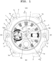
- This wristwatch includes a wristwatch case 1, as shown in FIG. 1 .
- band attachment sections 2 to which watch bands (not shown in the drawings) are attached are provided.
- switch sections 3 are provided on the two o'clock side, four o'clock side, eight o' clock side, and ten o' clock side of this wristwatch case 1, switch sections 3 are provided.
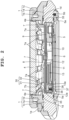
- this wristwatch includes a lower case 1a, an upper case 1b, and an exterior case 1c, as shown in FIG. 1 and FIG. 2 .
- the lower case 1a and the upper case 1b are made of metal, and the upper case 1b is attached to the lower case 1a by a plurality of screws 1e via a waterproof ring 1d.
- the exterior case 1c is made of an elastic synthetic resin such as urethane resin, and attached covering the outer circumferential part of the upper part of the upper case 1b by a plurality of screws 1f.
- a watch glass 4 is attached via a packing 4a, as shown in FIG. 2 .
- a back cover 5 is attached by a plurality of screws 5b via a waterproof packing 5a.
- a timepiece module 6 is provided in this wristwatch case 1, or more specifically, in the lower case 1a.
- a ring-shaped parting member 7 is provided, as shown in FIG. 1 and FIG. 2 .
- a plurality of hour marks 7a which corresponds to one o'clock to twelve o'clock is arranged at equal intervals.
- This parting member 7 is structured such that a later-described dial 8 of the timepiece module 6 is arranged therebelow.
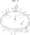
- the timepiece module 6 includes a housing 10 made of a synthetic resin, as shown in FIG. 2 and FIG. 3 .
- a solar panel 9 is provided while being held down by a later-described panel hold down member 35.
- the light-transmissive dial 8 which is transparent or semi-transparent is arranged.
- a circuit board 11 is attached by a plurality of screws 11a, as shown in FIG. 2 and FIG. 4 .
- a metal hold down plate 12 is arranged, as shown in FIG. 2 and FIG. 4 .
- This hold down plate 12 which is located on a substantially half area of the housing 10 on the six o'clock side, is structured such that hook sections 12a formed on plural portions on its outer peripheral part are engaged with engaging projections 10a formed on the outer circumferential surface of the housing 10, as shown in FIG. 3 and FIG. 9 .
- the hold down plate 12 is attached to the housing 10 while holding down the circuit board 11 on the housing 10.
- the housing 10 has provided therein a display panel 13 which electrooptically displays various information necessary for timepiece functions such as information regarding a time of day, a date, and a day of the week, a first timepiece movement 14 which drives pointers 14a such as a minute pointer and an hour pointer, a second timepiece movement 15 which drives a function pointer 15a, and a battery housing section 16 which houses a button-shaped battery 17, as shown in FIG. 5 .
- a display panel 13 which electrooptically displays various information necessary for timepiece functions such as information regarding a time of day, a date, and a day of the week
- a first timepiece movement 14 which drives pointers 14a such as a minute pointer and an hour pointer
- a second timepiece movement 15 which drives a function pointer 15a
- a battery housing section 16 which houses a button-shaped battery 17, as shown in FIG. 5 .
- the display panel 13 which is a planar display element such as a liquid crystal display element or an electroluminescence (EL) display element, is formed in a substantially rectangular shape and diagonally arranged from the three o'clock side to the six o'clock side of the housing 10, as shown in FIG. 2 and FIG. 5 .
- This display panel 13 is supported on the circuit board 11 while being electrically connected thereto by an interconnector 13a.
- the solar panel 9 has display window sections 9a formed in its two portions on the three o'clock side and the six o'clock side, and is structured such that information displayed on the display panel 13 can be checked through these display window sections 9a, as shown in FIG. 3 .
- the first timepiece movement 14 includes a first step motor and a first gear train mechanism, and is provided in a substantially central portion of the housing 10, as shown in FIG. 5 .
- This first timepiece movement 14 is structured such that a pointer shaft 14b protrudes above the dial 8 through the solar panel 9 and the dial 8, the pointers 14a are attached to an upper end portion of this protruding pointer shaft 14b, and the pointers 14a are driven above the dial 8, as shown in FIG. 3 .
- the second timepiece movement 15 includes a second step motor and a second gear train mechanism, and is provided on the nine o'clock side of the housing 10, as shown in FIG. 5 .
- This second timepiece movement 15 is structured such that a function pointer shaft 15b protrudes above the dial 8 through the solar panel 9 and the dial 8, the function pointer 15a is attached to an upper end portion of this protruding function pointer shaft 15b, and the function pointer 15a is driven above the dial 8, as shown in FIG. 3 .
- the battery housing section 16 is formed in a circular recess shape whose size is substantially equal to that of the battery 17 and provided on a substantially one o'clock side of the housing 10, as shown in FIG. 4 to FIG. 6 .
- a battery hold down section 18 which holds down the battery 17 housed therein and electrically connects an electrode surface 17a serving as the minus electrode of the battery 17 to the circuit board 11, and an electrode terminal 20 which electrically connects an outer circumferential surface 17b serving as the plus electrode of the battery 17 to the circuit board 11 are provided, as shown in FIG. 4 to FIG. 6 .
- the battery hold down section 18 is formed on the metal hold down plate 12 that holds down the circuit board 11 on the housing 10, and positioned extending across the battery housing section 16 from the three o'clock side toward a substantially twelve o'clock side, as shown in FIG. 4 .
- a plurality of contacting pieces 18a which comes in contact with the electrode surface 17a of the battery 17 is provided.
- this battery hold down section 18 is pulled upward by its portion on the three o'clock side of the hold down plate 12 being bent, as shown in FIG. 8 .
- this battery hold down section 18 is structured such that a battery hook section 18b formed on its rim portion on the twelve o'clock side engages with an engaging section 10b provided on the twelve o'clock side of the housing 10 and positioned outside the battery housing section 16, as shown in FIG. 4 .
- this battery hold down section 18 holds down the battery 17 on the battery housing section 16 with the plurality of contacting pieces 18a being in contact with the electrode surface 17a of the battery 17.
- the electrode terminal 20 includes a main body section 21 which is held close to an inner circumferential portion of the battery housing section 16, and a first contact section 22 which is provided on a side portion of the main body section 21 and comes in contact with the outer circumferential surface 17b of the battery 17 housed in the battery housing section 16, as shown in FIG. 5 to FIG. 7 .
- this electrode terminal 20 includes a second contact section 23 which is provided on one end portion (upper end portion in FIG. 7 ) of the main body section 21 on the circuit board 11 side and against which the circuit board 11 is pressed, and a receiving section 24 which is formed on the other end portion (lower end portion in FIG. 7 ) of the main body section 21 on the side opposite to the circuit board 11 and against which a non-electrode surface 17c of the battery 17 on the side opposite to the electrode surface 17a is pressed.
- This electrode terminal 20 is formed such that the main body section 21, the first contact section 22, the second contact section 23, and the receiving section 24 are integrally formed by a conductive metal plate such as stainless steel being subjected to bend processing such as press processing and sheet metal processing, as shown in FIG. 7 .
- the main body section 21 is vertically formed in a flat plate shape and held by a holding section 25 provided close to the inner circumferential part of the battery housing section 16, as shown in FIG. 5 and FIG. 6 .
- the holding section 25, which holds the main body section 21 of the electrode terminal 20 at three points, is provided close to an inner circumferential portion of the battery housing section 16 located substantially diagonally to an inner circumferential portion of the battery housing section 16 located in the outer circumferential part of the housing 10, as shown in FIG. 5 and FIG. 6 . More specifically, the holding section 25 is provided close to an inner circumferential portion of the battery housing section 16 located on a virtual straight line intersecting with a virtual straight line extending in the longitudinal direction of the battery hold down section 18 and on a virtual straight line extending from the twelve o'clock side toward the six o'clock side.
- This holding section 25 includes three holding wall sections 25a to 25c.
- two holding wall sections 25a and 25b are provided in the inner circumferential part of the battery housing section 16, as shown in FIG. 5 and FIG. 6 .
- the remaining one holding wall section 25c is provided outside the battery housing section 16 with its semi-cylindrical projection corresponding to a middle point between the two holding wall sections 25a and 25b.
- the holding section 25 is structured such that, by being inserted and held between the two holding wall sections 25a and 25b and the one holding wall section 25c, the main body section 21 is held in a manner to be tiltable.
- the first contact section 22 extends from a side portion of the main body section 21 along the inner circumferential surface of the battery housing section 16, and an edge section 22a of the extending first contact section 22 is bent in a radial direction toward the inner side of the battery housing section 16, as shown in FIG. 5 to FIG. 7 .
- This first contact section 22 is structured such that the leading end side of the bent edge section 22a protrudes into the battery housing section 16, and this leading end comes in contact with the outer circumferential surface 17b of the battery 17 housed in the battery housing section 16.
- the edge section 22a of the first contact section 22 is formed in a tapered shape whose side section (upper side section in FIG. 7 ) 22b opposing the circuit board 11 has been inclined toward the side opposite to the circuit board 11 (lower side in FIG. 7 ), as shown in FIG. 7 .
- this edge section 22a of the first contact section 22 is structured such that, when an outer circumferential portion of the battery 17 comes in contact with the side section 22b protruding in the battery housing section 16 from diagonally above, this outer circumferential portion of the battery 17 slides along the inclined side section 22b, whereby the battery 17 is housed in the battery housing section 16, as shown in FIG. 5 .
- a terminal housing section 26 in which the first contact section 22 is arranged is formed along the inner circumferential surface of the battery housing section 16, as shown in FIG. 5 .
- This terminal housing section 26 is open toward the inner side of the battery housing section 16, and structured such that the end portion of the tapered edge section 22a of the first contact section 22 protrudes into the battery housing section 16 from this open portion.
- the second contact section 23 is formed extending in the same direction as the first contact section 22 from one end portion (upper end portion in FIG. 7 ) of the main body section 21 on the circuit board 11 side in a manner to be gradually away from the first contact section 22 and to obliquely extend toward the circuit board 11 (upper side in FIG. 7 ), as shown in FIG. 5 and FIG. 7 .
- the second contact section 23 is structured such that its obliquely extending edge section 23a protrudes from the housing 10 toward the circuit board 11 side and an electrode (not shown in the drawings) of the circuit board 11 is pressed against this protruding edge section 23a.
- the second contact section 23 is structured such that, when the circuit board 11 is arranged on the lower surface (upper surface in FIG. 6 ) of the housing 10 and attached thereto by the plurality of screws 11a, this second contact section 23 is pressed toward the housing 10 side by the circuit board 11, as shown in FIG. 6 and FIG. 7 .
- the main body section 21 is structured such that, when the second contact section 23 is pressed by the circuit board 11, this main body section 21 is tilted at an inclination angle ⁇ with it being held by the holding section 25 of the housing 10, and the first contact section 22 is tilted at the inclination angle ⁇ toward the side opposite to the circuit board 11 (lower side in FIG. 7 ) along with this tilting of the main body section 21.
- an edge section 24a extending toward the center of the inner area of the battery housing section 16 is obliquely bent toward the non-electrode surface 17c of the battery 17 (upper side in FIG. 6 ) arranged in the battery housing section 16.
- the main body section 21 has been held by the holding section 25 without being tilted
- the first contact section 22 has been arranged in the terminal housing section 26 without being tilted
- the second contact section 23 has been tilted toward the circuit board 11 side from the housing 10
- the edge section 23a has been arranged protruding from the housing 10 toward the circuit board 11 side
- the receiving section 24 has been arranged in parallel with the bottom part of the battery housing section 16, as shown in FIG. 5 .
- this electrode terminal 20 is structured such that, when the circuit board 11 is arranged on and attached to the upper surface of the housing 10, the second contact section 23 is pressed by the circuit board 11, whereby the main body section 21 is tilted at the inclination angle ⁇ , and the first contact section 22 and the receiving section 24 are tilted in the same direction at the same inclination angle ⁇ along with this tilting of the main body section 21, as shown in FIG. 6 .
- this electrode terminal 20 is structured such that, when the battery 17 is arranged in the battery housing section 16 and held down by the battery hold down section 18 in the state shown in FIG. 6 , the receiving section 24 is pressed by the non-electrode surface 17c of the battery 17 and its tilting is released with the second contact section 23 being pressed against the circuit board 11, and the tilting of the main body section 21 and that of the first contact section 22 are released along therewith.
- this electrode terminal 20 is structured such that, when the receiving section 24 is pressed by the non-electrode surface 17c of the battery 17 in the state shown in FIG. 6 and its tilting is released such that the receiving section 24 becomes parallel to the bottom part of the battery housing section 16, the tilting of the main body section 21 and that of the first contact section 22 are released with the second contact section 23 being pressed against the circuit board 11, whereby the main body section 21 returns to its initial state.
- this electrode terminal 20 is structured such that, when the main body section 21 returns to its initial state from the state shown in FIG. 6 , the tilting of the first contact section 22 is released and the first contact section 22 returns to its initial state with the second contact section 23 being pressed against the circuit board 11, whereby the leading end side of the edge section 22a of the first contact section 22 is upwardly shifted to correspond to a substantially middle portion of the outer circumferential surface 17b of the battery 17 in a thickness direction (vertical direction), and this leading end of the edge section 22a reliably comes in contact with the outer circumferential surface 17b of the battery 17.
- the timepiece module 6 includes a lighting device 30 which illuminates the dial 8 that is an illumination target, as shown in FIG. 2 and FIG. 3 .
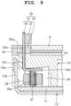
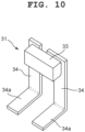
- This lighting device 30 includes a light emitting member 31 which illuminates the upper surface of the dial 8 and an attachment adjusting member 32 which holds this light emitting member 31, as shown in FIG. 9 and FIG. 10 .
- the light emitting member 31 includes a light emitting section 33 which emits light and a pair of supporting legs 34 which serves as contact sections that are electrically connected to a pair of electrodes of this light emitting section 33 (not shown in the drawings) and support the light emitting section 33.
- the light emitting section 33 is a light source such as a light emitting diode (LED) whose outer shape is a chip shape that is a rectangular box shape, and the pair of electrodes is provided to be exposed on its back surface, as shown in FIG. 9 and FIG. 10 .
- the pair of supporting legs 34 is made of a conductive metal and has a belt plate shape. This pair of supporting legs 34 is arranged on and attached to the back surface of the light emitting section 33 while being electrically connected to the pair of electrodes exposed to the back surface side.
- the pair of supporting legs 34 is formed such that its vertical length is sufficiently greater than the total length of the vertical length of the light emitting section 33 and the vertical length of the attachment adjusting member 32, as shown in FIG. 9 and FIG. 10 .
- the pair of supporting legs 34 is structured to support the light emitting section 33 with this light emitting section 33 protruding above the attachment adjusting member 32.
- the attachment adjusting member 32 is made of an insulative synthetic resin and has a substantially rectangular shape, as shown in FIG. 3 and FIG. 9 .
- This attachment adjusting member 32 is structured to be independently arranged while enabling the adjustment of the arrangement of the light emitting section 33 on a predetermined portion of the outer circumferential part of the dial 8 with the pair of supporting legs 34 being held by this attachment adjusting member 32.
- a pair of attachment holes 32a into which the pair of supporting legs 34 is inserted is provided penetrating vertically.
- This pair of attachment holes 32a is formed such that its cross-sections have the same shape as those of the pair of supporting legs 34.
- This attachment adjusting member 32 is structured to be arranged in a predetermined portion of a ring-shaped panel hold down member 35 which serves as an arrangement member that holds down the upper surface of the outer circumferential part of the solar panel 9 arranged below the dial 8, as shown in FIG. 3 and FIG. 9 .
- the shape, size, height, color and the like of the attachment adjusting member 32 are determined in accordance with the panel hold down member 35 whose shape, size and height vary depending on the type of wristwatch. Accordingly, for example, this attachment adjusting member 32 is formed as a separate component and arranged in an attachment housing section 35a provided on the five o'clock side of the panel hold down member 35.
- the panel hold down member 35 is structured to be arranged on the upper surface of the outer circumferential part of the housing 10 and hold down the upper surface of the outer circumferential part of the solar panel 9 on the housing 10, as shown in FIG. 3 and FIG. 9 . Also, this panel hold down member 35 is formed to surround the outer circumferential part of the dial 8 arranged on the solar panel 9. Moreover, this panel hold down member 35 is structured such that its shape, size, height and the like are determined in accordance with the type of wristwatch.
- a cutout section 36 is provided which is larger than the attachment adjusting member 32 and extends from the outer circumferential part of the housing 10 toward the central side of the housing 10, as shown in FIG. 2 and FIG. 9 .
- a pair of insertion holes 10c into which the pair of supporting legs 34 of the light emitting member 31 is inserted is coaxially provided with the pair of attachment holes 32a of the attachment adjusting member 32 while corresponding to the cutout section 36.
- the pair of supporting legs 34 is formed such that its lower end portions are inserted into the insertion holes 10c of the housing 10 and protrude downward, these lower end portions downwardly protruding from the pair of insertion holes 10c are bent with the attachment adjusting member 32 being arranged in the attachment housing section 35a of the panel hold down member 35, and these bent sections 34a are pressed against the upper inner surface of the cutout section 36, as shown in FIG. 9 .
- the pair of supporting legs 34 is formed such that their bending points are determined in accordance with the heights of the panel hold down member 35 and the cutout section 36 of the housing 10, as shown in FIG. 2 and FIG. 9 .
- the pair of supporting legs 34 is structured to attach and fix the light emitting member 31 and the attachment adjusting member 32 to the housing 10 by the bent sections 34a being pressed against the upper inner surface of the cutout section 36 by a pair of connecting members 37.
- the attachment adjusting member 32 is formed to arrange the light emitting section 33 above the dial 8.
- the pair of connecting members 37 is provided in the cutout section 36 of the housing 10, as shown in FIG. 9 .
- Each of the pair of connecting members 37 is a coil spring and held by an attachment member 38.
- This pair of connecting members 37 is structured such that one end portions thereof come in resilient contact with a pair of electrodes (not shown in the drawings) of the circuit board 11 corresponding to the cutout section 36 of the housing 10, and the other end portions come in resilient contact with the bent sections 34a of the pair of supporting legs 34.
- the pair of connecting members 37 is structured to electrically connect the light emitting section 33 with the circuit board 11 via the pair of supporting legs 34, as shown in FIG. 9 .
- the attachment member 38 is formed in a rectangular plate shape, in which a pair of holding holes 38a which holds the pair of connecting member 37 is provided penetrating vertically.
- the pair of connecting member 37 is structured to be inserted into the pair of holding holes 38a and held while protruding above and below this pair of holding holes 38a.
- a light emitter housing section 7b is provided which is open toward the inner side of the wristwatch case 1 and in which the light emitting section 33 is arranged, as shown in FIG. 2 .
- the lighting device 30 is structured such that light from the light emitting section 33 arranged in the light emitter housing section 7b of the parting member 7 is emitted toward the upper surface of the dial 8 from the open side of the light emitter housing section 7b so as to illuminate the dial 8.
- this attachment adjusting member 32 can be undesirably seen from the inner side of the wristwatch case 1 through this open portion, as shown in FIG. 2 . Accordingly, this attachment adjusting member 32 should preferably be colored in a color that is hard to be recognized from the inner side of the wristwatch case 1, such as a color similar to that of the parting member 7 or black.
- the parting member 7 is inserted into and arranged in the upper opening of the wristwatch case 1 from above.
- the light emitter housing section 7b of the parting member 7 is positioned corresponding to the five o'clock side of the wristwatch case 1.
- the watch glass 4 and the packing 4a are attached to the upper opening of the wristwatch case 1 located above the parting member 7.
- the timepiece module 6 is mounted in the wristwatch case 1 from below.
- the timepiece module 6 is assembled.
- the display panel 13 is arranged in a portion ranging from the three o'clock side to the six o'clock side of the housing 10.
- the first timepiece movement 14 is arranged in a substantially central portion of the housing 10, and the second timepiece movement 15 is arranged on the nine o'clock side of the housing 10.
- the solar panel 9 is arranged on the upper surface of the housing 10 such that the display window sections 9a on the three o'clock side and nine o'clock side of the solar panel 9 are positioned corresponding to the display panel 13.
- the panel hold down member 35 is arranged on the outer circumferential part of the housing 10, and thereby holds down the upper surface of the outer circumferential part of the solar panel 9.
- the attachment housing section 35a provided on the five o'clock side of the panel hold down member 35 is positioned corresponding to the cutout section 36 provided on the five o'clock side of the housing 10.
- the lighting device 30 can be arranged. More specifically, the lighting device 30 is attached to the attachment housing section 35a of the panel hold down member 35 which holds down so as to attach the solar panel 9 to the housing 10.
- the pair of supporting legs 34 is attached to the back surface of the light emitting section 33 of the light emitting member 31 so as to electrically connect the pair of electrodes (not shown in the drawings) of the light emitting section 33 to the pair of supporting legs 34.
- the light emitting member 31 where the light emitting section 33 is supported by the pair of supporting legs 34 is assembled.
- the pair of supporting legs 34 of this light emitting member 31 is inserted from above into the pair of attachment holes 32a of the attachment adjusting member 32 and protrudes below.
- the light emitting member 31 is attached to the attachment adjusting member 32.
- the attachment adjusting member 32 is arranged in the attachment housing section 35a of the panel hold down member 35 as a separate component. Note that the shape, size, height, color, and the like of this attachment adjusting member 32 have been determined in accordance with the panel hold down member 35 whose shape, size, and height vary depending on the type of wristwatch.
- the pair of supporting legs 34 protruding below the attachment adjusting member 32 is inserted into the pair of insertion holes 10c of the housing 10 located below the attachment housing section 35a of the panel hold down member 35 in a manner to protrude into the cutout section 36 of the housing 10.
- the pair of supporting legs 34 protruding in the cutout section 36 is bent and the bent sections 34a of the pair of supporting legs 34 are pressed against the upper inner surface of the cutout section 36.
- the attachment adjusting member 32 and the light emitting member 31 are attached to and fixed to the housing 10 by the pair of supporting legs 34.
- the light emitting section 33 of the light emitting member 31 has been arranged above the panel hold down member 35, and the pair of connecting members 37 can be arranged below the bent sections 34a of the pair of supporting legs 34.
- the lighting device 30 is attached to the five o' clock side of the housing 10 while being arranged in the attachment housing section 35a of the panel hold down member 35.
- the electrode terminal 20 is attached to the area close to the inner circumferential part of the battery housing section 16 of the housing 10.
- the main body section 21 of the electrode terminal 20 is inserted into and held by the holding section 25 provided close to the inner circumferential part of the battery housing section 16. More specifically, the main body section 21 is inserted into the space between the two holding wall sections 25a and 25b and the one holding wall section 25c and held between these two holding wall sections 25a and 25b and the one holding wall section 25c.
- the first contact section 22 of the electrode terminal 20 is arranged in the terminal housing section 26 formed in the inner circumferential part of the battery housing section 16. More specifically, the edge section 22a of the first contact section 22 extending from the side portion of the main body section 21 along the inner circumferential surface of the battery housing section 16 has been bent in the radial direction toward the inner side of the battery housing section 16, so that the leading end side of this bent edge section 22a protrudes into the battery housing section 16.
- the second contact section 23 of the electrode terminal 20 is arranged on the side of the circuit board 11 (upper side in FIG. 7 ) attached to the housing 10. More specifically, the second contact section 23 is extending in a substantially same direction as the first contact section 22 from one end portion (upper end portion in FIG. 7 ) of the main body section 21 on the circuit board 11 side in a manner to be gradually away from the first contact section 22 and to obliquely extend toward the circuit board 11 side (upper side in FIG. 7 ), and the edge section 23a thereof is arranged protruding from the housing 10 toward the circuit board 11 side.
- the receiving section 24 of the electrode terminal 20 is arranged on the bottom part of the battery housing section 16 on the side opposite to the circuit board 11. More specifically, the receiving section 24 is extending from the other end portion (lower end portion in FIG. 7 ) of the main body section 21 toward the center of the inner area of the battery housing section 16 in parallel with the bottom surface of the battery housing section 16, and the edge section 24a thereof is obliquely arranged toward the non-electrode surface 17c side (upper side in FIG. 6 ) of the battery 17 which is to be arranged in the battery housing section 16.
- This state is the initial state of the electrode terminal 20. In other words, this is the state before the circuit board 11 is attached to the housing 10.
- the main body section 21 has been held by the holding section 25 without being tilted, and the first contact section 22 has been arranged in the terminal housing section 26 without being tilted.
- the second contact section 23 has been inclined toward the circuit board 11 side from the housing 10, the edge section 23a has been arranged protruding from the housing 10 toward the circuit board 11 side, and the receiving section 24 has been arranged in parallel with the bottom part of the battery housing section 16.
- the circuit board 11 is arranged on the lower surface of the housing 10 and attached thereto by the plurality of screws 11a, as shown in FIG. 9 .
- the pair of connecting members 37 which is to electrically connect the lighting device 30 to the circuit board 11 is held by the pair of holding holes 38a of the attachment member 38, and arranged in the cutout section 36 of the housing 10 by this attachment member 38 in a manner to be positioned below the bent sections 34a of the pair of supporting legs 34 of the lighting device 30.
- the circuit board 11 When being attached to the housing 10, the circuit board 11 is pressed against the second contact section 23 of the electrode terminal 20, whereby the second contact section 23 is pressed toward the housing 10 side (lower side in FIG. 7 ) in a manner to be flexurally deformed, as shown in FIG. 6 .
- the main body section 21 is tilted at the inclination angle ⁇ while being held by the holding section 25, the first contact section 22 is tilted at the inclination angle ⁇ toward the side opposite to the circuit board 11 side along with the tilting of the main body section 21, and the receiving section 24 is also tilted at the same inclination angle ⁇ in the same direction.
- the metal hold down plate 12 is arranged on and attached to the lower surface of the circuit board 11.
- the hold down plate 12 is arranged on a substantially half area of the housing 10 on the six o'clock side with reference to a substantially straight virtual line connecting the three o' clock side of the circuit board 11 with the nine o' clock side thereof, and the hook sections 12a formed on the plural portions on the outer peripheral part of the hold down plate 12 are engaged with the engaging projections 10a formed on the outer circumferential surface of the housing 10.
- the hold down plate 12 is attached to the housing 10 in a manner to hold down the circuit board 11 on the housing 10.
- the battery hold down section 18 formed on the three o' clock side of the hold down plate 12 has been arranged extending across the battery housing section 16 from the three o'clock side toward a substantially twelve o'clock side.
- the battery hook section 18b provided on the rim portion of the battery hold down section 18 on the twelve o'clock side can be engaged with the engaging section 10b provided on the twelve o'clock side of the housing 10 and positioned outside the battery housing section 16.
- the battery 17 can be housed in the battery housing section 16.
- the battery 17 When the battery 17 is to be housed in the battery housing section 16, first, the engaging of the battery hook section 18b of the battery hold down section 18 with the engaging section 10b on the twelve o' clock side of the housing 10 is released, and the battery hold down section 18 is pulled upward in a direction to be away from the battery housing section 16 (refer to FIG. 8 ) . As a result, the battery housing section 16 is opened, and then the battery 17 is inserted into the battery housing section 16. More specifically, the battery 17 is inserted from obliquely above into the battery housing section 16 in a direction substantially perpendicular to the longitudinal direction of the battery hold down section 18 from the outer circumferential part side of the housing 10.
- the outer circumferential part of the battery 17 comes in contact with the edge section 22a, which constitutes the first contact section 22 of the electrode terminal 20 provided close to the inner circumferential part of the battery housing section 16 and is protruding in the battery housing section 16, from obliquely above.
- the first contact section 22 has been obliquely tilted at the inclination angle ⁇ toward the side opposite to the circuit board 11 (lower side in FIG. 7 )
- the outer circumferential part of the battery 17 smoothly slides along this tilted first contact section 22, whereby the battery 17 is housed in the battery housing section 16.
- the outer circumferential part of the battery 17 comes in contact with the side section 22b of the tapered edge section 22a of the first contact section 22 from obliquely above.
- the side section 22b of the edge section 22a is further tilted toward the side opposite to the circuit board 11 with the first contact section 22 being tilted toward the side opposite to the circuit board 11 (lower side in FIG. 7 ) at the inclination angle ⁇ , and the outer circumferential part of the battery 17 further smoothly slides along this tilted side section 22b, whereby the battery 17 is housed in the battery housing section 16. Accordingly, even though the edge section 22a of the first contact section 22 is protruding in the battery housing section 16, the edge section 22a of the first contact section 22 does not become obstructive, whereby the battery 17 is easily and favorably housed in the battery housing section 16.
- the battery hold down section 18 is arranged on the battery 17 and the battery hook section 18b provided on the rim portion of the battery hold down section 18 on the twelve o'clock side is engaged with the engaging section 10b provided on the twelve o'clock side of the housing 10 and positioned outside the battery housing section 16.
- the battery hold down section 18 holds down the battery 17 on the battery housing section 16 with the plurality of contacting pieces 18a being in contact with the electrode surface 17a of the battery 17.
- the battery 17 is held down on the battery housing section 16 by the battery hold down section 18.
- the receiving section 24 is pressed by the non-electrode surface 17c of the battery 17 with the second contact section 23 being pressed against the circuit board 11, the tilting of the receiving section 24 is released, and the tilting of the main body section 21 and that of the first contact section 22 are released along therewith. More specifically, this receiving section 24 is pressed by the non-electrode surface 17c such that its tilting is released and the receiving section 24 becomes parallel to the bottom part of the battery housing section 16
- the tilting of the main body section 21 and that of the first contact section 22 are released, whereby the main body section 21 and the first contact section 22 return to their initial states .
- the first contact section 22 also returns to the initial state with the second contact section 23 being pressed against the circuit board 11 and electrically connected to the circuit board 11 stably, and the leading end side of the edge section 22a of the first contact section 22 is upwardly shifted to correspond to a substantially middle portion of the outer circumferential surface 17b of the battery 17 in the thickness direction (vertical direction), whereby the leading end of the edge section 22a reliably and favorably comes in contact with the outer circumferential surface 17b of the battery 17.
- the battery 17 is electrically connected to the circuit board 11 by the electrode terminal 20 and the battery hold down section 18.
- the timepiece module 6 is mounted in the wristwatch case 1.
- the dial 8 is arranged on the solar panel 9 arranged on the upper surface of the housing 10 and the outer circumferential part of the dial 8 is surrounded by the panel hold down member 35.
- the pointer shaft 14b of the first timepiece movement 14 and the function pointer shaft 15b of the second timepiece movement 15 protrude above the dial 8.
- the pointers 14a are attached to the pointer shaft 14b of the first timepiece movement 14
- the function pointer 15a is attached to the function pointer shaft 15b of the second timepiece movement
- the timepiece module 6 is mounted in the wristwatch case 1, and the dial 8 is arranged below the parting member 7.
- the light emitting section 33 of the lighting device 30 arranged above the panel hold down member 35 is arranged in the light emitter housing section 7b of the parting member 7 so as to be arranged above the dial 8.
- the timepiece module 6 is favorably mounted in the wristwatch case 1.
- the switch sections 3 are attached to the two o'clock side, four o'clock side, eight o'clock side and ten o'clock side of the wristwatch case 1, and the back cover 5 is attached to the lower part of the wristwatch case 1 together with the waterproof packing 5a.
- the assembly of the wristwatch is completed.
- the pointers 14a are driven above the dial 8 by the first timepiece movement 14 so as to indicate a time of day
- the function pointer 15a is driven above the dial 8 by the second timepiece movement 15 so as to indicate a function.
- information such as a time of day, a date, and a day of the week displayed on the display panel 13 can be viewed from above the dial 8 through the display window sections 9a on the three o' clock side and six o'clock side of the solar panel 9.
- one of the plurality of switch sections 3 on the two o' clock side, four o' clock side, eight o' clock side and ten o' clock side is operated to select a lighting mode where the light emitting section 33 of the light emitting member 31 of the lighting device 30 emits light to illuminate the dial 8. More specifically, since the light emitting section 33 has been arranged in the light emitter housing section 7b of the parting member 7 while being arranged above the dial 8 by the attachment adjusting member 32, and this light emitter housing section 7b is open toward the dial 8 side, light from the light emitting section 33 is emitted toward the upper surface of the dial 8 from this open portion.
- the dial 8 is illuminated by the lighting device 30, the display of a time of day by the pointers 14a, the display of a function by the function pointer 15a, and the display of information by the display panel 13 can be favorably viewed even in a dark condition. Also, the light emitter housing section 7b of the parting member 7 is open toward the dial 8 side.
- the attachment adjusting member 32 can be undesirably seen from the inner side of the wristwatch case 1 through this open portion.
- this attachment adjusting member 32 is hard to be recognized from the inner side of the wristwatch case 1, which enhances the design.
- the electrode terminal 20 of this wristwatch includes the main body section 21 which is held in the circumferential rim portion of the battery housing section 16 that houses the battery 17, the first contact section 22 which is provided on the main body section 21 and comes in contact with the outer circumferential surface 17b of the battery 17 housed in the battery housing section 16, and the second contact section 23 which is provided on the portion of the main body section 21 located on the side of the circuit board 11 that is arranged on an outer surface of the battery housing section 16, and pressed against the circuit board 11 in a manner to tilt the first contact section 22 and the main body section 21 toward the side opposite to the circuit board 11.
- the housing of the battery 17 can be facilitated.
- the edge section 22a of the first contact section 22 protrudes into the battery housing section 16. Accordingly, the outer circumferential part of the battery 17 comes in contact with the edge section 22a of the first contact section 22 when the battery 17 is housed in the battery housing section 16. However, since the first contact section 22 has been tilted toward the side opposite to the circuit board 11, the outer circumferential part of the battery 17 can smoothly slide along the tilted first contact section 22. As a result of this structure, the edge section 22a of the first contact section 22 does not become obstructive, and the battery 17 can be easily and favorably housed in the battery housing section 16, whereby the housing of the battery 17 can be facilitated.
- the first contact section 22 is provided along the inner circumferential surface of the battery housing section 16.
- the outer circumferential part of the battery 17 smoothly slides along the first contact section 22 provided along the inner circumferential surface of the battery housing section 16, whereby the battery 17 can be easily and favorably housed in the battery housing section 16.
- the main body section 21 is held by the holding section 25 in the circumferential rim portion of the battery housing section 16 in a manner to be tiltable .
- the main body section 21 held by the holding section 25 can be easily tilted, whereby the first contact section 22 can be favorably tilted toward the side opposite to the circuit board 11.
- the holding section 25 includes the three holding wall sections 25a to 25c which hold the main body section 21 at the three points.
- the two holding wall sections 25a and 25b are arranged on the inner side of the circumferential rim portion of the battery housing section 16, and the remaining one holding wall section 25c having the semi-cylindrical projection is arranged outside the battery housing section 16 with its projection corresponding to the middle point between the two holding wall sections 25a and 25b.
- the main body section 21 can be favorably held between the two holding wall sections 25a and 25b and the one holding wall section 25c in a manner to be tiltable.
- the edge section 22a of the first contact section 22 extending from the side portion of the main body section 21 along the inner circumferential surface of the battery housing section 16 comes in contact with the outer circumferential surface 17b of the battery 17, and the edge section 23a of the second contact section 23 extending in a substantially same direction as the first contact section 22 from the one end portion of the main body section 21 on the circuit board 11 side in a manner to be gradually away from the first contact section 22 is pressed against the circuit board 11.
- the second contact section 23 pressed by the circuit board 11 toward the battery housing section 16 side the first contact section 22 and the main body section 21 can be favorably tilted toward the side opposite to the circuit board 11.
- the edge section 22a of the first contact section 22 has the tapered shape where the side section 22b opposing the circuit board 11 has been formed inclining toward the side opposite to the circuit board 11.
- the receiving section 24, against which the non-electrode surface 17c that is one surface of the battery 17 housed in the battery housing section 16 is pressed is formed on the other end portion of the main body section 21 on the side opposite to the circuit board 11.
- the receiving section 24 is also tilted in the same direction. In this state, when the battery 17 housed in the battery housing section 16 is pressed against the receiving section 24, the tilting of the receiving section 24 is released, whereby the tilting of the main body section 21 and that of the first contact section 22 can be released.
- this electrode terminal 20 when the battery 17 is housed in the battery housing section 16 and the non-electrode surface 17c of the battery 17 is pressed, the tilting of the receiving section 24 is released with the second contact section 23 being pressed against the circuit board 11, and the tilting of the main body section 21 and that of the first contact section 22 are released along therewith.
- the main body section 21 and the first contact section 22 have been tilted toward the side opposite to the circuit board 11 in the state before the battery 17 is housed in the battery housing section 16, the tilting of the main body section 21 and that of the first contact section 22 can be released.
- this electrode terminal 20 returns to the state before the second contact section 23 is pressed against the circuit board 11, that is, the initial state where the main body section 21 is held by the holding section 25, and the first contact section 22 returns to the initial state along therewith, whereby the leading end side of the edge section 22a of the first contact section 22 can be upwardly shifted.
- the leading end side of the edge section 22a can be positioned corresponding to a substantially middle portion of the outer circumferential surface 17b of the battery 17 in the thickness direction, the leading end of the edge section 22a can reliably and favorably come in contact with the outer circumferential surface 17b that serves as the plus electrode of the battery 17 housed in the battery housing section 16.
- the outer circumferential surface 17b serving as the plus electrode of the battery 17 and the circuit board 11 can be electrically connected to each other reliably and favorably.
- the edge section 22a of the first contact section 22 of the electrode terminal 20 protrudes into the battery housing section 16.
- the outer circumferential portion of the battery 17 can smoothly slide along the tilted first contact section 22 even when the outer circumferential part of the battery 17 comes in contact with the edge section 22a of the first contact section 22 during the housing of the battery 17 in the battery housing section 16.
- the edge section 22a of the first contact section 22 does not become obstructive and the battery 17 can be easily and favorably housed in the battery housing section 16, whereby the housing of the battery 17 can be facilitated.
- this timepiece module 6 includes the battery hold down section 18 which comes in contact with the electrode surface 17a that is the other surface on the side opposite to the non-electrode surface 17c of the battery 17 housed in the battery housing section 16, holds down the battery 17 on the battery housing section 16, and electrically connects the battery 17 to the circuit board 11.
- the battery hold down section 18 the battery 17 can be reliably held down on and favorably housed in the battery housing section 16, and the electrode surface 17a serving as the minus electrode of the battery 17 and the circuit board 11 can be electrically connected to each other reliably and favorably.
- the non-electrode surface 17c of the battery 17 can be reliably pressed against the receiving section 24 of the electrode terminal 20, whereby the tilting of the receiving section 24 can be reliably released, and the edge section 22a of the first contact section 22 can favorably come in contact with the outer circumferential surface 17b serving as the plus electrode of the battery 17 with the second contact section 23 being pressed against the circuit board 11.
- the outer circumferential surface 17b serving as the plus electrode of the battery 17 and the circuit board 11 can be electrically connected to each other reliably.
- the battery housing section 16 is formed in the circumferential rim portion of the housing 10, and the first contact section 22 is provided on the circumferential rim side of the housing 10 so as to be positioned away from the center of the housing 10.
- the battery housing section 16 and the first contact section 22 can be favorably provided in the housing 10 in a manner not to obstruct these components.
- the lighting device 30 is provided on the five o'clock side of the dial 8.
- the lighting device 30 is not necessarily required to be provided on the five o'clock side and may be provided on an arbitrary outer circumferential portion of the dial 8.
- the lighting device 30 illuminates the dial 8.
- the illumination target is not necessarily required to be the dial 8, and the lighting device 30 may illuminate a different target such as the display panel 13.
- the lighting device is arranged around the display panel 13.
- the present invention is applied to a wristwatch.
- the application target of the present invention is not necessarily required to be a wristwatch, and the present invention is applicable to various types of timepieces such as a travel watch, an alarm clock, a table clock, and a wall clock.
- the application target of the present invention is not necessarily required to be a timepiece, and the present invention is also applicable to various types of electronic devices such as a cellular phone and a portable information terminal.
- the housing of the battery can be facilitated.
Landscapes
- Physics & Mathematics (AREA)
- General Physics & Mathematics (AREA)
- Chemical & Material Sciences (AREA)
- Chemical Kinetics & Catalysis (AREA)
- Electrochemistry (AREA)
- General Chemical & Material Sciences (AREA)
- Engineering & Computer Science (AREA)
- Power Engineering (AREA)
- Life Sciences & Earth Sciences (AREA)
- Biophysics (AREA)
- Computer Hardware Design (AREA)
- Electric Clocks (AREA)
Abstract
Description
- The present invention relates to an electrode terminal that is used for electronic devices such as wristwatches, cellular phones, and portable information terminals, a module equipped with the electrode terminal, and a timepiece equipped with the electrode terminal and the module.
- For example, a battery housing structure for housing a button-shaped battery is known in which an electrode terminal that comes in contact with the outer circumferential surface of a battery serving as a plus electrode includes a fixing section arranged on the inner circumferential rim of a battery housing section and a pair of contacting arm sections extending from the sides of the fixing section in the circumferential directions of the battery housing section, as described in
Patent Document 1. - Patent Document 1:
JP 2009-193843 A - In the case of the electrode terminal of this type of battery housing structure, the pair of contacting arm sections extending from the sides of the fixing section in the circumferential directions of the battery housing section are oriented to the inner side of the battery housing section, whereby the ends of this pair of extended contacting arm sections are arranged protruding toward the inner side of the battery housing section. As a result, this electrode terminal is structured such that, when a battery is housed in the battery housing section, the ends of the pair of contacting arm sections are pressed against the outer circumferential surface of the battery and flexurally deformed in directions to be pressed out of the inner side of the battery housing section.
- Accordingly, the electrode terminal of this type of battery housing structure has a problem in that, due to the ends of the pair of contacting arm sections protruding toward the inner side of the battery housing section, these protruding ends of the pair of contacting arm sections become obstructive and the battery collides with these ends of the pair of contacting arm sections when the battery is housed in the battery housing section, whereby the battery is difficult to be housed in the battery housing section and the housing of the battery is troublesome.
- An object of the present invention is to provide an electrode terminal which facilitates the housing of a battery, a module equipped with the electrode terminal, and a timepiece equipped with the electrode terminal and the module.
- An embodiment of the present invention is an electrode terminal characterized by comprising: a main body section which is held in a circumferential rim portion of a battery housing section that houses a battery; a first contact section which is provided on the main body section and comes in contact with an outer circumferential surface of the battery housed in the battery housing section; and a second contact section which is provided on a portion of the main body section located on a side of a circuit board that is arranged on an outer surface of the battery housing section and pressed against the circuit board in a manner to tilt the first contact section and the main body section toward a side opposite to the circuit board.
- According to the present invention, the housing of a battery can be facilitated.
-
-
FIG. 1 is an enlarged front view of an embodiment where the present invention has been applied in a wristwatch; -
FIG. 2 is an enlarged cross-sectional view of the wristwatch taken along the A-A arrow view inFIG. 1 ; -
FIG. 3 is an enlarged perspective view of a timepiece module shown inFIG. 2 ; -
FIG. 4 is an enlarged back view of the timepiece module shown inFIG. 3 ; -
FIG. 5 is an enlarged back view showing a state where a hold down plate and a circuit board have been detached from the timepiece module inFIG. 4 ; -
FIG. 6 is an enlarged perspective view showing a main portion of a battery housing section of the timepiece module inFIG. 5 , in which the circuit board has been arranged on a housing and an electrode terminal has been tilted; -
FIG. 7 is an enlarged perspective view of the electrode terminal of the battery housing section shown inFIG. 6 ; -
FIG. 8 is an enlarged perspective view showing a main portion of a battery hold down section inFIG. 6 before a battery is housed in and held down on the battery housing section; -
FIG. 9 is an enlarged cross-sectional view showing a main portion of a lighting device of the timepiece module inFIG. 2 ; and -
FIG. 10 is an enlarged perspective view of a light emitting member of the lighting device shown inFIG. 9 . - An embodiment where the present invention has been applied in a wristwatch will hereinafter be described with reference to
FIG. 1 to FIG. 10 . - This wristwatch includes a
wristwatch case 1, as shown inFIG. 1 . On the six o'clock side and twelve o'clock side of thiswristwatch case 1,band attachment sections 2 to which watch bands (not shown in the drawings) are attached are provided. On the two o'clock side, four o'clock side, eight o' clock side, and ten o' clock side of thiswristwatch case 1,switch sections 3 are provided. - Also, this wristwatch includes a
lower case 1a, anupper case 1b, and anexterior case 1c, as shown inFIG. 1 andFIG. 2 . Thelower case 1a and theupper case 1b are made of metal, and theupper case 1b is attached to thelower case 1a by a plurality ofscrews 1e via awaterproof ring 1d. Theexterior case 1c is made of an elastic synthetic resin such as urethane resin, and attached covering the outer circumferential part of the upper part of theupper case 1b by a plurality ofscrews 1f. - To the upper opening of this
wristwatch case 1, or in other words, to the upper opening of theupper case 1b, awatch glass 4 is attached via apacking 4a, as shown inFIG. 2 . To the lower part of thiswristwatch case 1, or in other words, to the lower part of thelower case 1a, aback cover 5 is attached by a plurality ofscrews 5b via awaterproof packing 5a. In thiswristwatch case 1, or more specifically, in thelower case 1a, atimepiece module 6 is provided. - In the inner circumferential part of the
wristwatch case 1, or more specifically, in the inner circumferential part of theupper case 1b located below thewatch glass 4, a ring-shaped parting member 7 is provided, as shown inFIG. 1 andFIG. 2 . On this partingmember 7, a plurality ofhour marks 7a which corresponds to one o'clock to twelve o'clock is arranged at equal intervals. Thisparting member 7 is structured such that a later-describeddial 8 of thetimepiece module 6 is arranged therebelow. - The
timepiece module 6 includes ahousing 10 made of a synthetic resin, as shown inFIG. 2 andFIG. 3 . On the upper surface of thehousing 10, asolar panel 9 is provided while being held down by a later-described panel hold downmember 35. On the upper surface of thissolar panel 9, the light-transmissive dial 8 which is transparent or semi-transparent is arranged. Also, to the lower surface of thehousing 10, acircuit board 11 is attached by a plurality ofscrews 11a, as shown inFIG. 2 andFIG. 4 . - On the lower surface of the
circuit board 11, a metal hold downplate 12 is arranged, as shown inFIG. 2 andFIG. 4 . This hold downplate 12, which is located on a substantially half area of thehousing 10 on the six o'clock side, is structured such thathook sections 12a formed on plural portions on its outer peripheral part are engaged withengaging projections 10a formed on the outer circumferential surface of thehousing 10, as shown inFIG. 3 andFIG. 9 . As a result, the hold downplate 12 is attached to thehousing 10 while holding down thecircuit board 11 on thehousing 10. - Also, the
housing 10 has provided therein adisplay panel 13 which electrooptically displays various information necessary for timepiece functions such as information regarding a time of day, a date, and a day of the week, afirst timepiece movement 14 which drivespointers 14a such as a minute pointer and an hour pointer, asecond timepiece movement 15 which drives afunction pointer 15a, and abattery housing section 16 which houses a button-shaped battery 17, as shown inFIG. 5 . - The
display panel 13, which is a planar display element such as a liquid crystal display element or an electroluminescence (EL) display element, is formed in a substantially rectangular shape and diagonally arranged from the three o'clock side to the six o'clock side of thehousing 10, as shown inFIG. 2 andFIG. 5 . Thisdisplay panel 13 is supported on thecircuit board 11 while being electrically connected thereto by aninterconnector 13a. Also, thesolar panel 9 hasdisplay window sections 9a formed in its two portions on the three o'clock side and the six o'clock side, and is structured such that information displayed on thedisplay panel 13 can be checked through thesedisplay window sections 9a, as shown inFIG. 3 . - The
first timepiece movement 14 includes a first step motor and a first gear train mechanism, and is provided in a substantially central portion of thehousing 10, as shown inFIG. 5 . Thisfirst timepiece movement 14 is structured such that apointer shaft 14b protrudes above thedial 8 through thesolar panel 9 and thedial 8, thepointers 14a are attached to an upper end portion of thisprotruding pointer shaft 14b, and thepointers 14a are driven above thedial 8, as shown inFIG. 3 . - The
second timepiece movement 15 includes a second step motor and a second gear train mechanism, and is provided on the nine o'clock side of thehousing 10, as shown inFIG. 5 . Thissecond timepiece movement 15 is structured such that afunction pointer shaft 15b protrudes above thedial 8 through thesolar panel 9 and thedial 8, thefunction pointer 15a is attached to an upper end portion of this protrudingfunction pointer shaft 15b, and thefunction pointer 15a is driven above thedial 8, as shown inFIG. 3 . - The
battery housing section 16 is formed in a circular recess shape whose size is substantially equal to that of thebattery 17 and provided on a substantially one o'clock side of thehousing 10, as shown inFIG. 4 to FIG. 6 . In thisbattery housing section 16, a battery hold downsection 18 which holds down thebattery 17 housed therein and electrically connects anelectrode surface 17a serving as the minus electrode of thebattery 17 to thecircuit board 11, and anelectrode terminal 20 which electrically connects an outercircumferential surface 17b serving as the plus electrode of thebattery 17 to thecircuit board 11 are provided, as shown inFIG. 4 to FIG. 6 . - The battery hold down
section 18 is formed on the metal hold downplate 12 that holds down thecircuit board 11 on thehousing 10, and positioned extending across thebattery housing section 16 from the three o'clock side toward a substantially twelve o'clock side, as shown inFIG. 4 . In a middle portion of the battery hold downsection 18, a plurality of contactingpieces 18a which comes in contact with theelectrode surface 17a of thebattery 17 is provided. When thebattery 17 is to be housed in thebattery housing section 16, this battery hold downsection 18 is pulled upward by its portion on the three o'clock side of the hold downplate 12 being bent, as shown inFIG. 8 . - Also, this battery hold down
section 18 is structured such that abattery hook section 18b formed on its rim portion on the twelve o'clock side engages with anengaging section 10b provided on the twelve o'clock side of thehousing 10 and positioned outside thebattery housing section 16, as shown inFIG. 4 . When thebattery hook section 18b engages with theengaging section 10b on the twelve o'clock side of the housing, this battery hold downsection 18 holds down thebattery 17 on thebattery housing section 16 with the plurality of contactingpieces 18a being in contact with theelectrode surface 17a of thebattery 17. - On the other hand, the
electrode terminal 20 includes amain body section 21 which is held close to an inner circumferential portion of thebattery housing section 16, and afirst contact section 22 which is provided on a side portion of themain body section 21 and comes in contact with the outercircumferential surface 17b of thebattery 17 housed in thebattery housing section 16, as shown inFIG. 5 to FIG. 7 . Also, thiselectrode terminal 20 includes asecond contact section 23 which is provided on one end portion (upper end portion inFIG. 7 ) of themain body section 21 on thecircuit board 11 side and against which thecircuit board 11 is pressed, and areceiving section 24 which is formed on the other end portion (lower end portion inFIG. 7 ) of themain body section 21 on the side opposite to thecircuit board 11 and against which anon-electrode surface 17c of thebattery 17 on the side opposite to theelectrode surface 17a is pressed. - This
electrode terminal 20 is formed such that themain body section 21, thefirst contact section 22, thesecond contact section 23, and the receivingsection 24 are integrally formed by a conductive metal plate such as stainless steel being subjected to bend processing such as press processing and sheet metal processing, as shown inFIG. 7 . Themain body section 21 is vertically formed in a flat plate shape and held by a holdingsection 25 provided close to the inner circumferential part of thebattery housing section 16, as shown inFIG. 5 andFIG. 6 . - The holding
section 25, which holds themain body section 21 of theelectrode terminal 20 at three points, is provided close to an inner circumferential portion of thebattery housing section 16 located substantially diagonally to an inner circumferential portion of thebattery housing section 16 located in the outer circumferential part of thehousing 10, as shown inFIG. 5 andFIG. 6 . More specifically, the holdingsection 25 is provided close to an inner circumferential portion of thebattery housing section 16 located on a virtual straight line intersecting with a virtual straight line extending in the longitudinal direction of the battery hold downsection 18 and on a virtual straight line extending from the twelve o'clock side toward the six o'clock side. This holdingsection 25 includes three holdingwall sections 25a to 25c. - Among these three holding
wall sections 25a to 25c, two holdingwall sections battery housing section 16, as shown inFIG. 5 andFIG. 6 . Also, the remaining one holdingwall section 25c is provided outside thebattery housing section 16 with its semi-cylindrical projection corresponding to a middle point between the two holdingwall sections section 25 is structured such that, by being inserted and held between the two holdingwall sections holding wall section 25c, themain body section 21 is held in a manner to be tiltable. - The
first contact section 22 extends from a side portion of themain body section 21 along the inner circumferential surface of thebattery housing section 16, and anedge section 22a of the extendingfirst contact section 22 is bent in a radial direction toward the inner side of thebattery housing section 16, as shown inFIG. 5 to FIG. 7 . Thisfirst contact section 22 is structured such that the leading end side of thebent edge section 22a protrudes into thebattery housing section 16, and this leading end comes in contact with the outercircumferential surface 17b of thebattery 17 housed in thebattery housing section 16. - The
edge section 22a of thefirst contact section 22 is formed in a tapered shape whose side section (upper side section inFIG. 7 ) 22b opposing thecircuit board 11 has been inclined toward the side opposite to the circuit board 11 (lower side inFIG. 7 ), as shown inFIG. 7 . As a result, thisedge section 22a of thefirst contact section 22 is structured such that, when an outer circumferential portion of thebattery 17 comes in contact with theside section 22b protruding in thebattery housing section 16 from diagonally above, this outer circumferential portion of thebattery 17 slides along theinclined side section 22b, whereby thebattery 17 is housed in thebattery housing section 16, as shown inFIG. 5 . - In the inner circumferential part of the
battery housing section 16, aterminal housing section 26 in which thefirst contact section 22 is arranged is formed along the inner circumferential surface of thebattery housing section 16, as shown inFIG. 5 . Thisterminal housing section 26 is open toward the inner side of thebattery housing section 16, and structured such that the end portion of the taperededge section 22a of thefirst contact section 22 protrudes into thebattery housing section 16 from this open portion. - The
second contact section 23 is formed extending in the same direction as thefirst contact section 22 from one end portion (upper end portion inFIG. 7 ) of themain body section 21 on thecircuit board 11 side in a manner to be gradually away from thefirst contact section 22 and to obliquely extend toward the circuit board 11 (upper side inFIG. 7 ), as shown inFIG. 5 andFIG. 7 . As a result, thesecond contact section 23 is structured such that its obliquely extendingedge section 23a protrudes from thehousing 10 toward thecircuit board 11 side and an electrode (not shown in the drawings) of thecircuit board 11 is pressed against this protrudingedge section 23a. - Also, the
second contact section 23 is structured such that, when thecircuit board 11 is arranged on the lower surface (upper surface inFIG. 6 ) of thehousing 10 and attached thereto by the plurality ofscrews 11a, thissecond contact section 23 is pressed toward thehousing 10 side by thecircuit board 11, as shown inFIG. 6 andFIG. 7 . As a result, themain body section 21 is structured such that, when thesecond contact section 23 is pressed by thecircuit board 11, thismain body section 21 is tilted at an inclination angle θ with it being held by the holdingsection 25 of thehousing 10, and thefirst contact section 22 is tilted at the inclination angle θ toward the side opposite to the circuit board 11 (lower side inFIG. 7 ) along with this tilting of themain body section 21. - The receiving
section 24, which is a plate spring, is provided extending from the other end portion (lower end portion inFIG. 7 ) of themain body section 21 located on the side opposite to thecircuit board 11 toward the center of the inner area of thebattery housing section 16 in parallel with the bottom surface of thebattery housing section 16, as shown inFIG. 5 to FIG. 7 . In this receivingsection 24, anedge section 24a extending toward the center of the inner area of thebattery housing section 16 is obliquely bent toward thenon-electrode surface 17c of the battery 17 (upper side inFIG. 6 ) arranged in thebattery housing section 16. - As a result, in the
electrode terminal 20 in an initial state before the circuit board is attached to thehousing 10, themain body section 21 has been held by the holdingsection 25 without being tilted, thefirst contact section 22 has been arranged in theterminal housing section 26 without being tilted, thesecond contact section 23 has been tilted toward thecircuit board 11 side from thehousing 10, theedge section 23a has been arranged protruding from thehousing 10 toward thecircuit board 11 side, and the receivingsection 24 has been arranged in parallel with the bottom part of thebattery housing section 16, as shown inFIG. 5 . - Also, this
electrode terminal 20 is structured such that, when thecircuit board 11 is arranged on and attached to the upper surface of thehousing 10, thesecond contact section 23 is pressed by thecircuit board 11, whereby themain body section 21 is tilted at the inclination angle θ, and thefirst contact section 22 and the receivingsection 24 are tilted in the same direction at the same inclination angle θ along with this tilting of themain body section 21, as shown inFIG. 6 . - Moreover, this
electrode terminal 20 is structured such that, when thebattery 17 is arranged in thebattery housing section 16 and held down by the battery hold downsection 18 in the state shown inFIG. 6 , the receivingsection 24 is pressed by thenon-electrode surface 17c of thebattery 17 and its tilting is released with thesecond contact section 23 being pressed against thecircuit board 11, and the tilting of themain body section 21 and that of thefirst contact section 22 are released along therewith. - More specifically, this
electrode terminal 20 is structured such that, when the receivingsection 24 is pressed by thenon-electrode surface 17c of thebattery 17 in the state shown inFIG. 6 and its tilting is released such that the receivingsection 24 becomes parallel to the bottom part of thebattery housing section 16, the tilting of themain body section 21 and that of thefirst contact section 22 are released with thesecond contact section 23 being pressed against thecircuit board 11, whereby themain body section 21 returns to its initial state. - Also, this
electrode terminal 20 is structured such that, when themain body section 21 returns to its initial state from the state shown inFIG. 6 , the tilting of thefirst contact section 22 is released and thefirst contact section 22 returns to its initial state with thesecond contact section 23 being pressed against thecircuit board 11, whereby the leading end side of theedge section 22a of thefirst contact section 22 is upwardly shifted to correspond to a substantially middle portion of the outercircumferential surface 17b of thebattery 17 in a thickness direction (vertical direction), and this leading end of theedge section 22a reliably comes in contact with the outercircumferential surface 17b of thebattery 17. - The
timepiece module 6 includes alighting device 30 which illuminates thedial 8 that is an illumination target, as shown inFIG. 2 andFIG. 3 . Thislighting device 30 includes alight emitting member 31 which illuminates the upper surface of thedial 8 and anattachment adjusting member 32 which holds thislight emitting member 31, as shown inFIG. 9 andFIG. 10 . Thelight emitting member 31 includes alight emitting section 33 which emits light and a pair of supportinglegs 34 which serves as contact sections that are electrically connected to a pair of electrodes of this light emitting section 33 (not shown in the drawings) and support thelight emitting section 33. - The
light emitting section 33 is a light source such as a light emitting diode (LED) whose outer shape is a chip shape that is a rectangular box shape, and the pair of electrodes is provided to be exposed on its back surface, as shown inFIG. 9 andFIG. 10 . The pair of supportinglegs 34 is made of a conductive metal and has a belt plate shape. This pair of supportinglegs 34 is arranged on and attached to the back surface of thelight emitting section 33 while being electrically connected to the pair of electrodes exposed to the back surface side. - Also, the pair of supporting
legs 34 is formed such that its vertical length is sufficiently greater than the total length of the vertical length of thelight emitting section 33 and the vertical length of theattachment adjusting member 32, as shown inFIG. 9 andFIG. 10 . As a result, the pair of supportinglegs 34 is structured to support thelight emitting section 33 with thislight emitting section 33 protruding above theattachment adjusting member 32. - The
attachment adjusting member 32 is made of an insulative synthetic resin and has a substantially rectangular shape, as shown inFIG. 3 andFIG. 9 . Thisattachment adjusting member 32 is structured to be independently arranged while enabling the adjustment of the arrangement of thelight emitting section 33 on a predetermined portion of the outer circumferential part of thedial 8 with the pair of supportinglegs 34 being held by thisattachment adjusting member 32. Here, in thisattachment adjusting member 32, a pair ofattachment holes 32a into which the pair of supportinglegs 34 is inserted is provided penetrating vertically. This pair ofattachment holes 32a is formed such that its cross-sections have the same shape as those of the pair of supportinglegs 34. - This
attachment adjusting member 32 is structured to be arranged in a predetermined portion of a ring-shaped panel hold downmember 35 which serves as an arrangement member that holds down the upper surface of the outer circumferential part of thesolar panel 9 arranged below thedial 8, as shown inFIG. 3 andFIG. 9 . The shape, size, height, color and the like of theattachment adjusting member 32 are determined in accordance with the panel hold downmember 35 whose shape, size and height vary depending on the type of wristwatch. Accordingly, for example, thisattachment adjusting member 32 is formed as a separate component and arranged in anattachment housing section 35a provided on the five o'clock side of the panel hold downmember 35. - The panel hold down
member 35 is structured to be arranged on the upper surface of the outer circumferential part of thehousing 10 and hold down the upper surface of the outer circumferential part of thesolar panel 9 on thehousing 10, as shown inFIG. 3 andFIG. 9 . Also, this panel hold downmember 35 is formed to surround the outer circumferential part of thedial 8 arranged on thesolar panel 9. Moreover, this panel hold downmember 35 is structured such that its shape, size, height and the like are determined in accordance with the type of wristwatch. - Also, in a lower portion of the
housing 10 corresponding to theattachment adjusting member 32, acutout section 36 is provided which is larger than theattachment adjusting member 32 and extends from the outer circumferential part of thehousing 10 toward the central side of thehousing 10, as shown inFIG. 2 andFIG. 9 . In thehousing 10, a pair ofinsertion holes 10c into which the pair of supportinglegs 34 of thelight emitting member 31 is inserted is coaxially provided with the pair ofattachment holes 32a of theattachment adjusting member 32 while corresponding to thecutout section 36. - Thus, the pair of supporting
legs 34 is formed such that its lower end portions are inserted into the insertion holes 10c of thehousing 10 and protrude downward, these lower end portions downwardly protruding from the pair ofinsertion holes 10c are bent with theattachment adjusting member 32 being arranged in theattachment housing section 35a of the panel hold downmember 35, and thesebent sections 34a are pressed against the upper inner surface of thecutout section 36, as shown inFIG. 9 . - Accordingly, the pair of supporting
legs 34 is formed such that their bending points are determined in accordance with the heights of the panel hold downmember 35 and thecutout section 36 of thehousing 10, as shown inFIG. 2 andFIG. 9 . Also, the pair of supportinglegs 34 is structured to attach and fix thelight emitting member 31 and theattachment adjusting member 32 to thehousing 10 by thebent sections 34a being pressed against the upper inner surface of thecutout section 36 by a pair of connectingmembers 37. Also, theattachment adjusting member 32 is formed to arrange thelight emitting section 33 above thedial 8. - The pair of connecting
members 37 is provided in thecutout section 36 of thehousing 10, as shown inFIG. 9 . Each of the pair of connectingmembers 37 is a coil spring and held by anattachment member 38. This pair of connectingmembers 37 is structured such that one end portions thereof come in resilient contact with a pair of electrodes (not shown in the drawings) of thecircuit board 11 corresponding to thecutout section 36 of thehousing 10, and the other end portions come in resilient contact with thebent sections 34a of the pair of supportinglegs 34. - More specifically, the pair of connecting
members 37 is structured to electrically connect thelight emitting section 33 with thecircuit board 11 via the pair of supportinglegs 34, as shown inFIG. 9 . Theattachment member 38 is formed in a rectangular plate shape, in which a pair of holdingholes 38a which holds the pair of connectingmember 37 is provided penetrating vertically. As a result, the pair of connectingmember 37 is structured to be inserted into the pair of holdingholes 38a and held while protruding above and below this pair of holdingholes 38a. - In the parting
member 7 arranged above the panel hold downmember 35, a lightemitter housing section 7b is provided which is open toward the inner side of thewristwatch case 1 and in which thelight emitting section 33 is arranged, as shown inFIG. 2 . As a result, thelighting device 30 is structured such that light from thelight emitting section 33 arranged in the lightemitter housing section 7b of the partingmember 7 is emitted toward the upper surface of thedial 8 from the open side of the lightemitter housing section 7b so as to illuminate thedial 8. - Here, since the light
emitter housing section 7b of the partingmember 7 is open toward the inner side of thewristwatch case 1, theattachment adjusting member 32 can be undesirably seen from the inner side of thewristwatch case 1 through this open portion, as shown inFIG. 2 . Accordingly, thisattachment adjusting member 32 should preferably be colored in a color that is hard to be recognized from the inner side of thewristwatch case 1, such as a color similar to that of the partingmember 7 or black. - Next, a procedure for assembling this
wristwatch case 1 is described. In this procedure, first, the partingmember 7 is inserted into and arranged in the upper opening of thewristwatch case 1 from above. Here, the lightemitter housing section 7b of the partingmember 7 is positioned corresponding to the five o'clock side of thewristwatch case 1. In this state, thewatch glass 4 and thepacking 4a are attached to the upper opening of thewristwatch case 1 located above the partingmember 7. - Then, the
timepiece module 6 is mounted in thewristwatch case 1 from below. Here, before this mounting, thetimepiece module 6 is assembled. In this assembly, first, thedisplay panel 13, thefirst timepiece movement 14, and thesecond timepiece movement 15 are attached to thehousing 10. More specifically, thedisplay panel 13 is arranged in a portion ranging from the three o'clock side to the six o'clock side of thehousing 10. Then, thefirst timepiece movement 14 is arranged in a substantially central portion of thehousing 10, and thesecond timepiece movement 15 is arranged on the nine o'clock side of thehousing 10. - In this state, the
solar panel 9 is arranged on the upper surface of thehousing 10 such that thedisplay window sections 9a on the three o'clock side and nine o'clock side of thesolar panel 9 are positioned corresponding to thedisplay panel 13. Then, the panel hold downmember 35 is arranged on the outer circumferential part of thehousing 10, and thereby holds down the upper surface of the outer circumferential part of thesolar panel 9. Here, theattachment housing section 35a provided on the five o'clock side of the panel hold downmember 35 is positioned corresponding to thecutout section 36 provided on the five o'clock side of thehousing 10. - As a result, the
lighting device 30 can be arranged. More specifically, thelighting device 30 is attached to theattachment housing section 35a of the panel hold downmember 35 which holds down so as to attach thesolar panel 9 to thehousing 10. In this attachment, first, the pair of supportinglegs 34 is attached to the back surface of thelight emitting section 33 of thelight emitting member 31 so as to electrically connect the pair of electrodes (not shown in the drawings) of thelight emitting section 33 to the pair of supportinglegs 34. - As a result, the
light emitting member 31 where thelight emitting section 33 is supported by the pair of supportinglegs 34 is assembled. The pair of supportinglegs 34 of thislight emitting member 31 is inserted from above into the pair ofattachment holes 32a of theattachment adjusting member 32 and protrudes below. By this insertion, thelight emitting member 31 is attached to theattachment adjusting member 32. In this state, theattachment adjusting member 32 is arranged in theattachment housing section 35a of the panel hold downmember 35 as a separate component. Note that the shape, size, height, color, and the like of thisattachment adjusting member 32 have been determined in accordance with the panel hold downmember 35 whose shape, size, and height vary depending on the type of wristwatch. - Then, the pair of supporting
legs 34 protruding below theattachment adjusting member 32 is inserted into the pair ofinsertion holes 10c of thehousing 10 located below theattachment housing section 35a of the panel hold downmember 35 in a manner to protrude into thecutout section 36 of thehousing 10. In this state, the pair of supportinglegs 34 protruding in thecutout section 36 is bent and thebent sections 34a of the pair of supportinglegs 34 are pressed against the upper inner surface of thecutout section 36. - As a result, the
attachment adjusting member 32 and thelight emitting member 31 are attached to and fixed to thehousing 10 by the pair of supportinglegs 34. In this state, thelight emitting section 33 of thelight emitting member 31 has been arranged above the panel hold downmember 35, and the pair of connectingmembers 37 can be arranged below thebent sections 34a of the pair of supportinglegs 34. By the above-described attachment, thelighting device 30 is attached to the five o' clock side of thehousing 10 while being arranged in theattachment housing section 35a of the panel hold downmember 35. - In this state, the
electrode terminal 20 is attached to the area close to the inner circumferential part of thebattery housing section 16 of thehousing 10. Here, themain body section 21 of theelectrode terminal 20 is inserted into and held by the holdingsection 25 provided close to the inner circumferential part of thebattery housing section 16. More specifically, themain body section 21 is inserted into the space between the two holdingwall sections holding wall section 25c and held between these two holdingwall sections holding wall section 25c. - Here, the
first contact section 22 of theelectrode terminal 20 is arranged in theterminal housing section 26 formed in the inner circumferential part of thebattery housing section 16. More specifically, theedge section 22a of thefirst contact section 22 extending from the side portion of themain body section 21 along the inner circumferential surface of thebattery housing section 16 has been bent in the radial direction toward the inner side of thebattery housing section 16, so that the leading end side of thisbent edge section 22a protrudes into thebattery housing section 16. - Also, here, the
second contact section 23 of theelectrode terminal 20 is arranged on the side of the circuit board 11 (upper side inFIG. 7 ) attached to thehousing 10. More specifically, thesecond contact section 23 is extending in a substantially same direction as thefirst contact section 22 from one end portion (upper end portion inFIG. 7 ) of themain body section 21 on thecircuit board 11 side in a manner to be gradually away from thefirst contact section 22 and to obliquely extend toward thecircuit board 11 side (upper side inFIG. 7 ), and theedge section 23a thereof is arranged protruding from thehousing 10 toward thecircuit board 11 side. - Simultaneously, the receiving
section 24 of theelectrode terminal 20 is arranged on the bottom part of thebattery housing section 16 on the side opposite to thecircuit board 11. More specifically, the receivingsection 24 is extending from the other end portion (lower end portion inFIG. 7 ) of themain body section 21 toward the center of the inner area of thebattery housing section 16 in parallel with the bottom surface of thebattery housing section 16, and theedge section 24a thereof is obliquely arranged toward thenon-electrode surface 17c side (upper side inFIG. 6 ) of thebattery 17 which is to be arranged in thebattery housing section 16. - This state is the initial state of the
electrode terminal 20. In other words, this is the state before thecircuit board 11 is attached to thehousing 10. In this initial state, themain body section 21 has been held by the holdingsection 25 without being tilted, and thefirst contact section 22 has been arranged in theterminal housing section 26 without being tilted. In addition, thesecond contact section 23 has been inclined toward thecircuit board 11 side from thehousing 10, theedge section 23a has been arranged protruding from thehousing 10 toward thecircuit board 11 side, and the receivingsection 24 has been arranged in parallel with the bottom part of thebattery housing section 16. - In this state, the
circuit board 11 is arranged on the lower surface of thehousing 10 and attached thereto by the plurality ofscrews 11a, as shown inFIG. 9 . Before this attachment, the pair of connectingmembers 37 which is to electrically connect thelighting device 30 to thecircuit board 11 is held by the pair of holdingholes 38a of theattachment member 38, and arranged in thecutout section 36 of thehousing 10 by thisattachment member 38 in a manner to be positioned below thebent sections 34a of the pair of supportinglegs 34 of thelighting device 30. - In this state, when the
circuit board 11 is attached to the lower surface of thehousing 10, the one end portions of the pair of connectingmember 37 come in resilient contact with the pair of electrodes (not shown in the drawings) of thecircuit board 11, and the other end portions come in resilient contact with thebent sections 34a of the pair of supportinglegs 34. As a result, thelight emitting section 33 and thecircuit board 11 are electrically connected to each other by the pair of connectingmembers 37 and the pair of supportinglegs 34. - When being attached to the
housing 10, thecircuit board 11 is pressed against thesecond contact section 23 of theelectrode terminal 20, whereby thesecond contact section 23 is pressed toward thehousing 10 side (lower side inFIG. 7 ) in a manner to be flexurally deformed, as shown inFIG. 6 . As a result, themain body section 21 is tilted at the inclination angle θ while being held by the holdingsection 25, thefirst contact section 22 is tilted at the inclination angle θ toward the side opposite to thecircuit board 11 side along with the tilting of themain body section 21, and the receivingsection 24 is also tilted at the same inclination angle θ in the same direction. - Then, the metal hold down
plate 12 is arranged on and attached to the lower surface of thecircuit board 11. Here, the hold downplate 12 is arranged on a substantially half area of thehousing 10 on the six o'clock side with reference to a substantially straight virtual line connecting the three o' clock side of thecircuit board 11 with the nine o' clock side thereof, and thehook sections 12a formed on the plural portions on the outer peripheral part of the hold downplate 12 are engaged with the engagingprojections 10a formed on the outer circumferential surface of thehousing 10. As a result, the hold downplate 12 is attached to thehousing 10 in a manner to hold down thecircuit board 11 on thehousing 10. - Here, the battery hold down
section 18 formed on the three o' clock side of the hold downplate 12 has been arranged extending across thebattery housing section 16 from the three o'clock side toward a substantially twelve o'clock side. In this state, thebattery hook section 18b provided on the rim portion of the battery hold downsection 18 on the twelve o'clock side can be engaged with the engagingsection 10b provided on the twelve o'clock side of thehousing 10 and positioned outside thebattery housing section 16. As a result, thebattery 17 can be housed in thebattery housing section 16. - When the
battery 17 is to be housed in thebattery housing section 16, first, the engaging of thebattery hook section 18b of the battery hold downsection 18 with the engagingsection 10b on the twelve o' clock side of thehousing 10 is released, and the battery hold downsection 18 is pulled upward in a direction to be away from the battery housing section 16 (refer toFIG. 8 ) . As a result, thebattery housing section 16 is opened, and then thebattery 17 is inserted into thebattery housing section 16. More specifically, thebattery 17 is inserted from obliquely above into thebattery housing section 16 in a direction substantially perpendicular to the longitudinal direction of the battery hold downsection 18 from the outer circumferential part side of thehousing 10. - In this insertion, the outer circumferential part of the
battery 17 comes in contact with theedge section 22a, which constitutes thefirst contact section 22 of theelectrode terminal 20 provided close to the inner circumferential part of thebattery housing section 16 and is protruding in thebattery housing section 16, from obliquely above. Here, since thefirst contact section 22 has been obliquely tilted at the inclination angle θ toward the side opposite to the circuit board 11 (lower side inFIG. 7 ), the outer circumferential part of thebattery 17 smoothly slides along this tiltedfirst contact section 22, whereby thebattery 17 is housed in thebattery housing section 16. - In addition, since the side section (upper side section in
FIG. 7 ) 22b of theedge section 22a of thefirst contact section 22 which is opposing thecircuit board 11 has been formed inclining toward the side opposite to thecircuit board 11 and the leading end side of theedge section 22a has been formed in the tapered shape, the outer circumferential part of thebattery 17 comes in contact with theside section 22b of the taperededge section 22a of thefirst contact section 22 from obliquely above. - Here, the
side section 22b of theedge section 22a is further tilted toward the side opposite to thecircuit board 11 with thefirst contact section 22 being tilted toward the side opposite to the circuit board 11 (lower side inFIG. 7 ) at the inclination angle θ, and the outer circumferential part of thebattery 17 further smoothly slides along this tiltedside section 22b, whereby thebattery 17 is housed in thebattery housing section 16. Accordingly, even though theedge section 22a of thefirst contact section 22 is protruding in thebattery housing section 16, theedge section 22a of thefirst contact section 22 does not become obstructive, whereby thebattery 17 is easily and favorably housed in thebattery housing section 16. - In this state, the battery hold down
section 18 is arranged on thebattery 17 and thebattery hook section 18b provided on the rim portion of the battery hold downsection 18 on the twelve o'clock side is engaged with the engagingsection 10b provided on the twelve o'clock side of thehousing 10 and positioned outside thebattery housing section 16. As a result, the battery hold downsection 18 holds down thebattery 17 on thebattery housing section 16 with the plurality of contactingpieces 18a being in contact with theelectrode surface 17a of thebattery 17. - Here, the
battery 17 is held down on thebattery housing section 16 by the battery hold downsection 18. As a result, the receivingsection 24 is pressed by thenon-electrode surface 17c of thebattery 17 with thesecond contact section 23 being pressed against thecircuit board 11, the tilting of the receivingsection 24 is released, and the tilting of themain body section 21 and that of thefirst contact section 22 are released along therewith. More specifically, this receivingsection 24 is pressed by thenon-electrode surface 17c such that its tilting is released and the receivingsection 24 becomes parallel to the bottom part of thebattery housing section 16 - Accordingly, the tilting of the
main body section 21 and that of thefirst contact section 22 are released, whereby themain body section 21 and thefirst contact section 22 return to their initial states . More specifically, in the state shown inFIG. 6 , when themain body section 21 returns to the initial state, thefirst contact section 22 also returns to the initial state with thesecond contact section 23 being pressed against thecircuit board 11 and electrically connected to thecircuit board 11 stably, and the leading end side of theedge section 22a of thefirst contact section 22 is upwardly shifted to correspond to a substantially middle portion of the outercircumferential surface 17b of thebattery 17 in the thickness direction (vertical direction), whereby the leading end of theedge section 22a reliably and favorably comes in contact with the outercircumferential surface 17b of thebattery 17. As a result, thebattery 17 is electrically connected to thecircuit board 11 by theelectrode terminal 20 and the battery hold downsection 18. - Then, the
timepiece module 6 is mounted in thewristwatch case 1. In this mounting, thedial 8 is arranged on thesolar panel 9 arranged on the upper surface of thehousing 10 and the outer circumferential part of thedial 8 is surrounded by the panel hold downmember 35. Here, thepointer shaft 14b of thefirst timepiece movement 14 and thefunction pointer shaft 15b of thesecond timepiece movement 15 protrude above thedial 8. In this state, thepointers 14a are attached to thepointer shaft 14b of thefirst timepiece movement 14, thefunction pointer 15a is attached to thefunction pointer shaft 15b of thesecond timepiece movement 15, thetimepiece module 6 is mounted in thewristwatch case 1, and thedial 8 is arranged below the partingmember 7. - Here, the
light emitting section 33 of thelighting device 30 arranged above the panel hold downmember 35 is arranged in the lightemitter housing section 7b of the partingmember 7 so as to be arranged above thedial 8. As a result, thetimepiece module 6 is favorably mounted in thewristwatch case 1. Subsequently, theswitch sections 3 are attached to the two o'clock side, four o'clock side, eight o'clock side and ten o'clock side of thewristwatch case 1, and theback cover 5 is attached to the lower part of thewristwatch case 1 together with thewaterproof packing 5a. As a result, the assembly of the wristwatch is completed. - Next, the usage of this wristwatch is described.
- In a normal state of this wristwatch, the
pointers 14a are driven above thedial 8 by thefirst timepiece movement 14 so as to indicate a time of day, and thefunction pointer 15a is driven above thedial 8 by thesecond timepiece movement 15 so as to indicate a function. Also, information such as a time of day, a date, and a day of the week displayed on thedisplay panel 13 can be viewed from above thedial 8 through thedisplay window sections 9a on the three o' clock side and six o'clock side of thesolar panel 9. - When this wristwatch is to be used in a dark condition such as nighttime, one of the plurality of
switch sections 3 on the two o' clock side, four o' clock side, eight o' clock side and ten o' clock side is operated to select a lighting mode where thelight emitting section 33 of thelight emitting member 31 of thelighting device 30 emits light to illuminate thedial 8. More specifically, since thelight emitting section 33 has been arranged in the lightemitter housing section 7b of the partingmember 7 while being arranged above thedial 8 by theattachment adjusting member 32, and this lightemitter housing section 7b is open toward thedial 8 side, light from thelight emitting section 33 is emitted toward the upper surface of thedial 8 from this open portion. - As a result, in this wristwatch, since the
dial 8 is illuminated by thelighting device 30, the display of a time of day by thepointers 14a, the display of a function by thefunction pointer 15a, and the display of information by thedisplay panel 13 can be favorably viewed even in a dark condition. Also, the lightemitter housing section 7b of the partingmember 7 is open toward thedial 8 side. - Accordingly, the
attachment adjusting member 32 can be undesirably seen from the inner side of thewristwatch case 1 through this open portion. However, by being colored in a color similar to that of the partingmember 7 or black, thisattachment adjusting member 32 is hard to be recognized from the inner side of thewristwatch case 1, which enhances the design. - As described above, the
electrode terminal 20 of this wristwatch includes themain body section 21 which is held in the circumferential rim portion of thebattery housing section 16 that houses thebattery 17, thefirst contact section 22 which is provided on themain body section 21 and comes in contact with the outercircumferential surface 17b of thebattery 17 housed in thebattery housing section 16, and thesecond contact section 23 which is provided on the portion of themain body section 21 located on the side of thecircuit board 11 that is arranged on an outer surface of thebattery housing section 16, and pressed against thecircuit board 11 in a manner to tilt thefirst contact section 22 and themain body section 21 toward the side opposite to thecircuit board 11. As a result, the housing of thebattery 17 can be facilitated. - More specifically, in this
electrode terminal 20, theedge section 22a of thefirst contact section 22 protrudes into thebattery housing section 16. Accordingly, the outer circumferential part of thebattery 17 comes in contact with theedge section 22a of thefirst contact section 22 when thebattery 17 is housed in thebattery housing section 16. However, since thefirst contact section 22 has been tilted toward the side opposite to thecircuit board 11, the outer circumferential part of thebattery 17 can smoothly slide along the tiltedfirst contact section 22. As a result of this structure, theedge section 22a of thefirst contact section 22 does not become obstructive, and thebattery 17 can be easily and favorably housed in thebattery housing section 16, whereby the housing of thebattery 17 can be facilitated. - Also, in this
electrode terminal 20, thefirst contact section 22 is provided along the inner circumferential surface of thebattery housing section 16. As a result, after coming in contact with theedge section 22a of thefirst contact section 22, the outer circumferential part of thebattery 17 smoothly slides along thefirst contact section 22 provided along the inner circumferential surface of thebattery housing section 16, whereby thebattery 17 can be easily and favorably housed in thebattery housing section 16. - Moreover, in this
electrode terminal 20, themain body section 21 is held by the holdingsection 25 in the circumferential rim portion of thebattery housing section 16 in a manner to be tiltable . As a result, when thesecond contact section 23 is pressed against thecircuit board 11, themain body section 21 held by the holdingsection 25 can be easily tilted, whereby thefirst contact section 22 can be favorably tilted toward the side opposite to thecircuit board 11. - More specifically, the holding
section 25 includes the three holdingwall sections 25a to 25c which hold themain body section 21 at the three points. Among these three holdingwall sections 25a to 25c, the two holdingwall sections battery housing section 16, and the remaining one holdingwall section 25c having the semi-cylindrical projection is arranged outside thebattery housing section 16 with its projection corresponding to the middle point between the two holdingwall sections main body section 21 can be favorably held between the two holdingwall sections holding wall section 25c in a manner to be tiltable. - Also, in this
electrode terminal 20, theedge section 22a of thefirst contact section 22 extending from the side portion of themain body section 21 along the inner circumferential surface of thebattery housing section 16 comes in contact with the outercircumferential surface 17b of thebattery 17, and theedge section 23a of thesecond contact section 23 extending in a substantially same direction as thefirst contact section 22 from the one end portion of themain body section 21 on thecircuit board 11 side in a manner to be gradually away from thefirst contact section 22 is pressed against thecircuit board 11. As a result of this structure, by thesecond contact section 23 pressed by thecircuit board 11 toward thebattery housing section 16 side, thefirst contact section 22 and themain body section 21 can be favorably tilted toward the side opposite to thecircuit board 11. - Moreover, in this
electrode terminal 20, theedge section 22a of thefirst contact section 22 has the tapered shape where theside section 22b opposing thecircuit board 11 has been formed inclining toward the side opposite to thecircuit board 11. As a result, when theedge section 22a of thefirst contact section 22 is tilted toward the side opposite to thecircuit board 11, theside section 22b of theedge section 22a can be further tilted toward the side opposite to thecircuit board 11. - By this structure, in this
electrode terminal 20, even though the outer circumferential part of thebattery 17 comes in contact with theedge section 22a of thefirst contact section 22 when thebattery 17 is housed in thebattery housing section 16, this outer circumferential part of thebattery 17 can more smoothly slide along theside section 22b of theedge section 22a further tilted when theedge section 22a of thefirst contact section 22 is tilted. As a result, thebattery 17 can be favorably housed in thebattery housing section 16. - Also, in this
electrode terminal 20, the receivingsection 24, against which thenon-electrode surface 17c that is one surface of thebattery 17 housed in thebattery housing section 16 is pressed, is formed on the other end portion of themain body section 21 on the side opposite to thecircuit board 11. As a result, when thesecond contact section 23 is pressed against thecircuit board 11 and thefirst contact section 22 is tilted toward the side opposite to thecircuit board 11 together with themain body section 21, the receivingsection 24 is also tilted in the same direction. In this state, when thebattery 17 housed in thebattery housing section 16 is pressed against the receivingsection 24, the tilting of the receivingsection 24 is released, whereby the tilting of themain body section 21 and that of thefirst contact section 22 can be released. - More specifically, in this
electrode terminal 20, when thebattery 17 is housed in thebattery housing section 16 and thenon-electrode surface 17c of thebattery 17 is pressed, the tilting of the receivingsection 24 is released with thesecond contact section 23 being pressed against thecircuit board 11, and the tilting of themain body section 21 and that of thefirst contact section 22 are released along therewith. As a result, even though themain body section 21 and thefirst contact section 22 have been tilted toward the side opposite to thecircuit board 11 in the state before thebattery 17 is housed in thebattery housing section 16, the tilting of themain body section 21 and that of thefirst contact section 22 can be released. - Thus, when the tilting of the
main body section 21 and that of thefirst contact section 22 are released with thesecond contact section 23 being pressed against thecircuit board 11, thiselectrode terminal 20 returns to the state before thesecond contact section 23 is pressed against thecircuit board 11, that is, the initial state where themain body section 21 is held by the holdingsection 25, and thefirst contact section 22 returns to the initial state along therewith, whereby the leading end side of theedge section 22a of thefirst contact section 22 can be upwardly shifted. - By this structure, in this
electrode terminal 20, since the leading end side of theedge section 22a can be positioned corresponding to a substantially middle portion of the outercircumferential surface 17b of thebattery 17 in the thickness direction, the leading end of theedge section 22a can reliably and favorably come in contact with the outercircumferential surface 17b that serves as the plus electrode of thebattery 17 housed in thebattery housing section 16. As a result, the outercircumferential surface 17b serving as the plus electrode of thebattery 17 and thecircuit board 11 can be electrically connected to each other reliably and favorably. - Also, in the case of the
timepiece module 6 of this wristwatch, theedge section 22a of thefirst contact section 22 of theelectrode terminal 20 protrudes into thebattery housing section 16. However, since thefirst contact section 22 is tilted toward the side opposite to thecircuit board 11, the outer circumferential portion of thebattery 17 can smoothly slide along the tiltedfirst contact section 22 even when the outer circumferential part of thebattery 17 comes in contact with theedge section 22a of thefirst contact section 22 during the housing of thebattery 17 in thebattery housing section 16. As a result of this structure, theedge section 22a of thefirst contact section 22 does not become obstructive and thebattery 17 can be easily and favorably housed in thebattery housing section 16, whereby the housing of thebattery 17 can be facilitated. - Moreover, this
timepiece module 6 includes the battery hold downsection 18 which comes in contact with theelectrode surface 17a that is the other surface on the side opposite to thenon-electrode surface 17c of thebattery 17 housed in thebattery housing section 16, holds down thebattery 17 on thebattery housing section 16, and electrically connects thebattery 17 to thecircuit board 11. As a result, by this battery hold downsection 18, thebattery 17 can be reliably held down on and favorably housed in thebattery housing section 16, and theelectrode surface 17a serving as the minus electrode of thebattery 17 and thecircuit board 11 can be electrically connected to each other reliably and favorably. - Furthermore, in the case of this
timepiece module 6, since thebattery 17 can be held down on and favorably housed in thebattery housing section 16 by the battery hold downsection 18, thenon-electrode surface 17c of thebattery 17 can be reliably pressed against the receivingsection 24 of theelectrode terminal 20, whereby the tilting of the receivingsection 24 can be reliably released, and theedge section 22a of thefirst contact section 22 can favorably come in contact with the outercircumferential surface 17b serving as the plus electrode of thebattery 17 with thesecond contact section 23 being pressed against thecircuit board 11. As a result, the outercircumferential surface 17b serving as the plus electrode of thebattery 17 and thecircuit board 11 can be electrically connected to each other reliably. - Still further, in the case of this
timepiece module 6, thebattery housing section 16 is formed in the circumferential rim portion of thehousing 10, and thefirst contact section 22 is provided on the circumferential rim side of thehousing 10 so as to be positioned away from the center of thehousing 10. As a result, even though thedisplay panel 13, thefirst timepiece movement 14, thesecond timepiece movement 15, and the like are mounted in thehousing 10, thebattery housing section 16 and thefirst contact section 22 can be favorably provided in thehousing 10 in a manner not to obstruct these components. - In the above-described embodiment, the
lighting device 30 is provided on the five o'clock side of thedial 8. However, in the present invention, thelighting device 30 is not necessarily required to be provided on the five o'clock side and may be provided on an arbitrary outer circumferential portion of thedial 8. - Also, in the above-described embodiment, the
lighting device 30 illuminates thedial 8. However, in the present invention, the illumination target is not necessarily required to be thedial 8, and thelighting device 30 may illuminate a different target such as thedisplay panel 13. In this case, the lighting device is arranged around thedisplay panel 13. - Moreover, in the above-described embodiment, the present invention is applied to a wristwatch. However, the application target of the present invention is not necessarily required to be a wristwatch, and the present invention is applicable to various types of timepieces such as a travel watch, an alarm clock, a table clock, and a wall clock. Also, the application target of the present invention is not necessarily required to be a timepiece, and the present invention is also applicable to various types of electronic devices such as a cellular phone and a portable information terminal.
- While the present invention has been described with reference to the preferred embodiments, it is intended that the invention be not limited by any of the details of the description therein but includes all the embodiments which fall within the scope of the appended claims.
- This application is based upon the
Japanese Patent Applications No. 2021-030309, filed February 26, 2021 2021-030312, filed February 26, 2021 Japanese Patent Applications No. 2021-030309 2021-030312 - According to the present invention, the housing of the battery can be facilitated.
-
- 1
- wristwatch case
- 3
- switch sections
- 4
- watch glass
- 5
- back cover
- 6
- timepiece module
- 7
- parting member
- 7b
- light emitter housing section
- 8
- dial
- 9
- solar panel
- 10
- housing
- 11
- circuit board
- 12
- hold down plate
- 13
- display panel
- 14
- first timepiece movement
- 15
- second timepiece movement
- 16
- battery housing section
- 17
- battery
- 17a
- electrode surface
- 17b
- outer circumferential surface
- 17c
- non-electrode surface
- 18
- battery hold down section
- 20
- electrode terminal
- 21
- main body section
- 22
- first contact section
- 22a
- edge section
- 22b
- side section
- 23
- second contact section
- 23a
- edge section
- 24
- receiving section
- 24a
- edge section
- 25
- holding section
- 25a to 25c
- holding wall sections
- 26
- terminal housing section
- 30
- lighting device
- 31
- light emitting member
- 32
- attachment adjusting member
- 32a
- attachment holes
- 33
- light emitting section
- 34
- supporting legs
- 35
- panel hold down member
- 35a
- attachment housing member
- 36
- cutout section
- 37
- connecting members
- θ
- inclination angle
Claims (11)
- An electrode terminal characterized by comprising:a main body section which is held in a circumferential rim portion of a battery housing section that houses a battery;a first contact section which is provided on the main body section and comes in contact with an outer circumferential surface of the battery housed in the battery housing section; anda second contact section which is provided on a portion of the main body section located on a side of a circuit board that is arranged on an outer surface of the battery housing section and pressed against the circuit board in a manner to tilt the first contact section and the main body section toward a side opposite to the circuit board.
- The electrode terminal according to claim 1, wherein the first contact section is provided along an inner circumferential surface of the battery housing section.
- The electrode terminal according to claim 1 or 2, wherein the main body section is held by a holding section provided in the circumferential rim portion of the battery housing section in a manner to be tiltable.
- The electrode terminal according to any one of claims 1 to 3, wherein an edge section of the first contact section extending from a side portion of the main body section along the inner circumferential surface of the battery housing section comes in contact with the outer circumferential surface of the battery, and an edge section of the second contact section extending in a substantially same direction as the first contact section from one end portion of the main body section on the circuit board side is pressed against the circuit board.
- The electrode terminal according to claim 4, wherein the edge section of the first contact section is formed in a tapered shape whose side section opposing the circuit board has been inclined toward the side opposite to the circuit board.
- The electrode terminal according to any one of claims 1 to 5, wherein a receiving section against which a non-electrode surface that is one surface of the battery housed in the battery housing section is pressed is provided on an other end portion of the main body section on the side opposite to the circuit board.
- The electrode terminal according to claim 6, wherein tilting of the receiving section is released when the non-electrode surface of the battery housed in the battery housing section is pressed against the receiving section, and tilting of the main body section and tilting of the first contact section are released along with the release of the tilting of the receiving section.
- A module characterized by comprising the electrode terminal according to any one of claims 1 to 7.
- The module according to claim 8 characterized by comprising;
a battery hold down section which comes in contact with an electrode surface that is an other surface on a side opposite to the non-electrode surface of the battery housed in the battery housing section, holds down the battery on the battery housing section, and electrically connects the battery to the circuit board. - The module terminal according to claim 8 or 9, wherein the battery housing section is provided in a circumferential rim portion of a housing, and
wherein the first contact section is provided on the circumferential rim side of the housing so as to be positioned away from center of the housing. - A timepiece characterized by comprising the module according to any one of claims 8 to 10.
Applications Claiming Priority (3)
| Application Number | Priority Date | Filing Date | Title |
|---|---|---|---|
| JP2021030309A JP7643088B2 (en) | 2021-02-26 | 2021-02-26 | Electrode terminal, module and watch |
| JP2021030312A JP7707575B2 (en) | 2021-02-26 | 2021-02-26 | Lighting devices, modules and clocks |
| PCT/JP2022/003908 WO2022181262A1 (en) | 2021-02-26 | 2022-01-26 | Electrode terminal, module, and watch |
Publications (2)
| Publication Number | Publication Date |
|---|---|
| EP4300217A1 true EP4300217A1 (en) | 2024-01-03 |
| EP4300217A4 EP4300217A4 (en) | 2025-03-19 |
Family
ID=83048130
Family Applications (1)
| Application Number | Title | Priority Date | Filing Date |
|---|---|---|---|
| EP22759303.5A Pending EP4300217A4 (en) | 2021-02-26 | 2022-01-26 | ELECTRODE TERMINAL, MODULE AND CLOCK |
Country Status (3)
| Country | Link |
|---|---|
| US (1) | US12517472B2 (en) |
| EP (1) | EP4300217A4 (en) |
| WO (1) | WO2022181262A1 (en) |
Family Cites Families (13)
| Publication number | Priority date | Publication date | Assignee | Title |
|---|---|---|---|---|
| JPH0216515Y2 (en) * | 1980-12-17 | 1990-05-08 | ||
| JP3673456B2 (en) * | 2000-08-21 | 2005-07-20 | アルプス電気株式会社 | Battery holder |
| JP2003227884A (en) | 2001-11-29 | 2003-08-15 | Casio Comput Co Ltd | Light-emitting display device and electronic equipment |
| JP4120302B2 (en) | 2002-07-19 | 2008-07-16 | カシオ計算機株式会社 | Electronics |
| JP4486301B2 (en) | 2002-08-23 | 2010-06-23 | 株式会社デンソー | Button type battery terminal and electric device using the same |
| JP2004132772A (en) | 2002-10-09 | 2004-04-30 | Casio Comput Co Ltd | Lighting device and electronic equipment using the same |
| JP2006184239A (en) * | 2004-12-28 | 2006-07-13 | Seiko Instruments Inc | Power feeding mechanism and electronic timepiece having the same |
| JP4761450B2 (en) | 2005-12-07 | 2011-08-31 | リコーエレメックス株式会社 | Portable watch with LED lighting |
| JP2008010301A (en) * | 2006-06-29 | 2008-01-17 | Iriso Denshi Kogyo Kk | Battery holder |
| JP2009193843A (en) | 2008-02-15 | 2009-08-27 | Calsonic Kansei Corp | Battery retention structure |
| JP6358569B2 (en) * | 2016-06-22 | 2018-07-18 | カシオ計算機株式会社 | Connection device and clock |
| JP7328069B2 (en) | 2019-08-13 | 2023-08-16 | 株式会社ディスコ | Holder removal tool |
| US11548089B2 (en) | 2019-08-15 | 2023-01-10 | Forney Industries, Inc. | Wire spool gun |
-
2022
- 2022-01-26 US US18/279,026 patent/US12517472B2/en active Active
- 2022-01-26 WO PCT/JP2022/003908 patent/WO2022181262A1/en not_active Ceased
- 2022-01-26 EP EP22759303.5A patent/EP4300217A4/en active Pending
Also Published As
| Publication number | Publication date |
|---|---|
| US20240295858A1 (en) | 2024-09-05 |
| WO2022181262A1 (en) | 2022-09-01 |
| US12517472B2 (en) | 2026-01-06 |
| EP4300217A4 (en) | 2025-03-19 |
Similar Documents
| Publication | Publication Date | Title |
|---|---|---|
| US10594021B2 (en) | Module and timepiece | |
| US4247928A (en) | Integral lightpipe and display holder for a timepiece | |
| JP2004271259A (en) | Clock module | |
| US4435088A (en) | Battery switch plate for a timepiece | |
| JP2003227884A (en) | Light-emitting display device and electronic equipment | |
| CN108398875A (en) | Clock and watch | |
| US12517472B2 (en) | Electrode terminal, module and watch | |
| JP7683760B2 (en) | Switchgear and Clocks | |
| JP4120302B2 (en) | Electronics | |
| US20230418232A1 (en) | Arm wearable device and timepiece | |
| JP7643088B2 (en) | Electrode terminal, module and watch | |
| JP7707575B2 (en) | Lighting devices, modules and clocks | |
| JP7334714B2 (en) | module and clock | |
| US12613498B2 (en) | Electronic device and timepiece | |
| JP7552021B2 (en) | Modules and Clocks | |
| JP2002286869A (en) | Electronic watch | |
| US12560893B2 (en) | Clip device and electronic timepiece | |
| JP6842643B2 (en) | Modules and clocks | |
| JP7215141B2 (en) | Battery holding device and clock | |
| JP2007078504A (en) | Clock module | |
| JPH10319152A (en) | Electronic device and method for assembling the same | |
| JP2006266843A (en) | Electronic timepiece | |
| JP2004200189A (en) | Electronic apparatus | |
| JPH06201853A (en) | Clock module | |
| JPH0894991A (en) | Electronic device with liquid crystal display |
Legal Events
| Date | Code | Title | Description |
|---|---|---|---|
| STAA | Information on the status of an ep patent application or granted ep patent |
Free format text: STATUS: THE INTERNATIONAL PUBLICATION HAS BEEN MADE |
|
| PUAI | Public reference made under article 153(3) epc to a published international application that has entered the european phase |
Free format text: ORIGINAL CODE: 0009012 |
|
| STAA | Information on the status of an ep patent application or granted ep patent |
Free format text: STATUS: REQUEST FOR EXAMINATION WAS MADE |
|
| 17P | Request for examination filed |
Effective date: 20230925 |
|
| AK | Designated contracting states |
Kind code of ref document: A1 Designated state(s): AL AT BE BG CH CY CZ DE DK EE ES FI FR GB GR HR HU IE IS IT LI LT LU LV MC MK MT NL NO PL PT RO RS SE SI SK SM TR |
|
| DAV | Request for validation of the european patent (deleted) | ||
| DAX | Request for extension of the european patent (deleted) | ||
| A4 | Supplementary search report drawn up and despatched |
Effective date: 20250213 |
|
| RIC1 | Information provided on ipc code assigned before grant |
Ipc: G04G 17/02 20060101ALI20250207BHEP Ipc: G04G 17/00 20130101ALI20250207BHEP Ipc: G04G 17/06 20060101ALI20250207BHEP Ipc: H01M 50/247 20210101ALI20250207BHEP Ipc: H01M 50/244 20210101ALI20250207BHEP Ipc: G04G 19/00 20060101ALI20250207BHEP Ipc: G04G 17/04 20060101ALI20250207BHEP Ipc: G04C 10/00 20060101AFI20250207BHEP |
|
| STAA | Information on the status of an ep patent application or granted ep patent |
Free format text: STATUS: EXAMINATION IS IN PROGRESS |
|
| 17Q | First examination report despatched |
Effective date: 20251029 |