EP4300211A1 - Development cartridge - Google Patents
Development cartridge Download PDFInfo
- Publication number
- EP4300211A1 EP4300211A1 EP22759501.4A EP22759501A EP4300211A1 EP 4300211 A1 EP4300211 A1 EP 4300211A1 EP 22759501 A EP22759501 A EP 22759501A EP 4300211 A1 EP4300211 A1 EP 4300211A1
- Authority
- EP
- European Patent Office
- Prior art keywords
- developing
- supply
- electrode
- casing
- roller
- Prior art date
- Legal status (The legal status is an assumption and is not a legal conclusion. Google has not performed a legal analysis and makes no representation as to the accuracy of the status listed.)
- Granted
Links
Images






Classifications
-
- G—PHYSICS
- G03—PHOTOGRAPHY; CINEMATOGRAPHY; ANALOGOUS TECHNIQUES USING WAVES OTHER THAN OPTICAL WAVES; ELECTROGRAPHY; HOLOGRAPHY
- G03G—ELECTROGRAPHY; ELECTROPHOTOGRAPHY; MAGNETOGRAPHY
- G03G15/00—Apparatus for electrographic processes using a charge pattern
- G03G15/06—Apparatus for electrographic processes using a charge pattern for developing
- G03G15/08—Apparatus for electrographic processes using a charge pattern for developing using a solid developer, e.g. powder developer
- G03G15/0822—Arrangements for preparing, mixing, supplying or dispensing developer
- G03G15/0865—Arrangements for supplying new developer
- G03G15/0867—Arrangements for supplying new developer cylindrical developer cartridges, e.g. toner bottles for the developer replenishing opening
-
- G—PHYSICS
- G03—PHOTOGRAPHY; CINEMATOGRAPHY; ANALOGOUS TECHNIQUES USING WAVES OTHER THAN OPTICAL WAVES; ELECTROGRAPHY; HOLOGRAPHY
- G03G—ELECTROGRAPHY; ELECTROPHOTOGRAPHY; MAGNETOGRAPHY
- G03G15/00—Apparatus for electrographic processes using a charge pattern
- G03G15/06—Apparatus for electrographic processes using a charge pattern for developing
- G03G15/08—Apparatus for electrographic processes using a charge pattern for developing using a solid developer, e.g. powder developer
- G03G15/0806—Apparatus for electrographic processes using a charge pattern for developing using a solid developer, e.g. powder developer on a donor element, e.g. belt, roller
- G03G15/0808—Apparatus for electrographic processes using a charge pattern for developing using a solid developer, e.g. powder developer on a donor element, e.g. belt, roller characterised by the developer supplying means, e.g. structure of developer supply roller
-
- G—PHYSICS
- G03—PHOTOGRAPHY; CINEMATOGRAPHY; ANALOGOUS TECHNIQUES USING WAVES OTHER THAN OPTICAL WAVES; ELECTROGRAPHY; HOLOGRAPHY
- G03G—ELECTROGRAPHY; ELECTROPHOTOGRAPHY; MAGNETOGRAPHY
- G03G21/00—Arrangements not provided for by groups G03G13/00 - G03G19/00, e.g. cleaning, elimination of residual charge
- G03G21/16—Mechanical means for facilitating the maintenance of the apparatus, e.g. modular arrangements
- G03G21/18—Mechanical means for facilitating the maintenance of the apparatus, e.g. modular arrangements using a processing cartridge, whereby the process cartridge comprises at least two image processing means in a single unit
- G03G21/1839—Means for handling the process cartridge in the apparatus body
-
- G—PHYSICS
- G03—PHOTOGRAPHY; CINEMATOGRAPHY; ANALOGOUS TECHNIQUES USING WAVES OTHER THAN OPTICAL WAVES; ELECTROGRAPHY; HOLOGRAPHY
- G03G—ELECTROGRAPHY; ELECTROPHOTOGRAPHY; MAGNETOGRAPHY
- G03G2215/00—Apparatus for electrophotographic processes
- G03G2215/00362—Apparatus for electrophotographic processes relating to the copy medium handling
- G03G2215/00535—Stable handling of copy medium
- G03G2215/00679—Conveying means details, e.g. roller
-
- G—PHYSICS
- G03—PHOTOGRAPHY; CINEMATOGRAPHY; ANALOGOUS TECHNIQUES USING WAVES OTHER THAN OPTICAL WAVES; ELECTROGRAPHY; HOLOGRAPHY
- G03G—ELECTROGRAPHY; ELECTROPHOTOGRAPHY; MAGNETOGRAPHY
- G03G2215/00—Apparatus for electrophotographic processes
- G03G2215/02—Arrangements for laying down a uniform charge
- G03G2215/021—Arrangements for laying down a uniform charge by contact, friction or induction
- G03G2215/025—Arrangements for laying down a uniform charge by contact, friction or induction using contact charging means having lateral dimensions related to other apparatus means, e.g. photodrum, developing roller
-
- G—PHYSICS
- G03—PHOTOGRAPHY; CINEMATOGRAPHY; ANALOGOUS TECHNIQUES USING WAVES OTHER THAN OPTICAL WAVES; ELECTROGRAPHY; HOLOGRAPHY
- G03G—ELECTROGRAPHY; ELECTROPHOTOGRAPHY; MAGNETOGRAPHY
- G03G2215/00—Apparatus for electrophotographic processes
- G03G2215/06—Developing structures, details
- G03G2215/0634—Developing device
- G03G2215/0636—Specific type of dry developer device
- G03G2215/0643—Electrodes in developing area, e.g. wires, not belonging to the main donor part
-
- G—PHYSICS
- G03—PHOTOGRAPHY; CINEMATOGRAPHY; ANALOGOUS TECHNIQUES USING WAVES OTHER THAN OPTICAL WAVES; ELECTROGRAPHY; HOLOGRAPHY
- G03G—ELECTROGRAPHY; ELECTROPHOTOGRAPHY; MAGNETOGRAPHY
- G03G2215/00—Apparatus for electrophotographic processes
- G03G2215/06—Developing structures, details
- G03G2215/066—Toner cartridge or other attachable and detachable container for supplying developer material to replace the used material
-
- G—PHYSICS
- G03—PHOTOGRAPHY; CINEMATOGRAPHY; ANALOGOUS TECHNIQUES USING WAVES OTHER THAN OPTICAL WAVES; ELECTROGRAPHY; HOLOGRAPHY
- G03G—ELECTROGRAPHY; ELECTROPHOTOGRAPHY; MAGNETOGRAPHY
- G03G2221/00—Processes not provided for by group G03G2215/00, e.g. cleaning or residual charge elimination
- G03G2221/16—Mechanical means for facilitating the maintenance of the apparatus, e.g. modular arrangements and complete machine concepts
- G03G2221/1651—Mechanical means for facilitating the maintenance of the apparatus, e.g. modular arrangements and complete machine concepts for connecting the different parts
- G03G2221/1654—Locks and means for positioning or alignment
Definitions
- the present disclosure relates to a developing cartridge including a developing roller.
- a developing cartridge that includes a casing, a developing roller, a supply roller, a developing electrode, a supply electrode, and an IC chip (see Patent Literature 1).
- the developing roller is rotatable about a developing axis extending in a first direction.
- the developing roller is positioned at one end portion of the casing in a second direction crossing the first direction.
- the supply roller is rotatable about a supply axis extending in the first direction.
- the supply roller is configured to supply toner to the developing roller.
- the developing electrode is configured to supply electricity to the developing roller.
- the supply electrode is configured to supply electricity to the supply roller.
- the IC chip has an electrical contact surface.
- the electrical contact surface is positioned at one end portion of the casing in the first direction.
- the developing electrode and the supply electrode are positioned at another end portion of the casing in the first direction. Further, in the second direction, the electrical contact surface is at generally at the same position as the developing electrode.
- the electrical contact surface is approximately the same as the position of the developing electrode in the second direction, the electrical contact surface is positioned near the developing roller. Accordingly, it is likely that the electrical contact surface may be contaminated by toner scattering from the developing roller.
- a developing cartridge includes a casing configured to accommodate toner therein, a developing roller rotatable about a developing axis extending in a first direction and positioned at one end portion of the casing in a second direction crossing the first direction, a developing electrode electrically connected to the developing roller and positioned at one end portion of the casing in the first direction, a supply roller rotatable about a supply axis extending in the first direction and configured to supply toner to the developing roller, a supply electrode electrically connected to the supply roller and positioned at the one end portion of the casing in the first direction, and an IC chip having an electrical contact surface positioned at the one end portion of the casing in the first direction.
- the electrical contact surface is positioned opposite the developing electrode with respect to a part of the supply electrode in the second direction.
- the electrical contact surface is positioned opposite the developing electrode with respect to the part of the supply electrode in the second direction, the electrical contact surface can be positioned far away from the developing roller. The electrical contact surface can be thus restrained from being contaminated with toner.
- the second direction may be perpendicular to the first direction.
- the developing cartridge may further include a handle positioned at another end portion of the casing in the second direction.
- the supply roller may be positioned between the developing roller and the handle in the second direction.
- the developing electrode may be made of electrically conductive resin.
- the supply electrode may be made of electrically conductive resin.
- the developing roller may include a developing-roller shaft extending in the first direction.
- the developing electrode may include: a developing bearing having a developing through-hole through which the developing-roller shaft is inserted; and a developing electrode surface electrically connected to the developing bearing.
- the developing electrode surface may be positioned at the one end portion of the casing in the first direction.
- the developing electrode surface may extend perpendicular to the first direction.
- the supply roller may include a supply-roller shaft extending in the first direction.
- the supply electrode may include: a supply bearing having a supply through-hole through which the supply-roller shaft is inserted; and a supply electrode surface electrically connected to the supply bearing.
- the supply electrode surface may be positioned at the one end portion of the casing in the first direction.
- the supply electrode surface may extend perpendicular to the first direction.
- the electrical contact surface may be positioned opposite the developing electrode surface with respect to the supply electrode surface in the second direction.
- the developing cartridge may further include an insulating member positioned between the developing electrode and the supply electrode.
- the developing cartridge may further include a coupling configured to transmit a driving force to the developing roller and the supply roller, and positioned at another end portion of the casing in the first direction.
- the developing electrode, the supply electrode, and the electrical contact surface are positioned at the one end portion of the casing in the first direction, while the coupling is positioned at the other end portion of the casing in the first direction. Hence, Vibration of the coupling to the developing electrode, the supply electrode, and the electrical contact surface is less likely to be transmitted to the developing electrode, the supply electrode, and the electrical contact surface.
- the electrical contact surface may be positioned opposite the developing electrode surface with respect to the supply electrode surface in a third direction crossing the first direction and the second direction.
- the third direction may be perpendicular to the first direction and the second direction.
- the electrical contact surface may be movable relative to the casing.
- the developing cartridge may be is attachable to and detachable from a drum frame of a drum cartridge.
- the drum cartridge may include a photosensitive drum rotatable about a drum axis extending in the first direction, and a lock lever configured to lock the developing cartridge to the drum frame.
- the electrical contact surface may be positioned opposite the lock lever in the first direction with respect to the casing in a state where the developing cartridge is attached to the drum frame.
- the drum cartridge may further include a pressure member configured to press the developing roller against the photosensitive drum.
- the electrical contact surface is positioned opposite the lock lever in the first direction with respect to the pressure member in the state where the developing cartridge is attached to the drum frame.
- the casing may have a first outer surface and a second outer surface spaced apart from the first outer surface in the first direction; and the developing electrode and the supply electrode may be positioned at the first outer surface.
- a distance in the first direction between the first outer surface of the casing and the electrical contact surface may be greater than a distance in the first direction between the first outer surface of the casing and the developing electrode.
- the distance in the first direction between the first outer surface of the casing and the electrical contact surface may be greater than a distance in the first direction between the first outer surface of the casing and the supply electrode.
- the developing electrode may include a developing protrusion protruding in the first direction and positioned at the one end portion of the casing in the first direction.
- the supply electrode may include a supply protrusion protruding in the first direction and positioned at the one end portion of the casing in the first direction.
- the electrical contact surface may be positioned opposite the developing protrusion with respect to the supply protrusion in the second direction.
- the developing protrusion may have a developing electrode surface; the supply protrusion may have a supply electrode surface; and the electrical contact surface may be positioned opposite the developing electrode surface with respect to the supply electrode surface in the second direction.
- the electrical contact surface can be suppressed from getting contaminated with toner.
- an image forming apparatus 1 includes a main housing 10, and a process cartridge 20.
- the main housing 10 is illustrated in a smaller size.
- the process cartridge 20 is attachable to and detachable from the main housing 10.
- the process cartridge 20 includes a developing cartridge 30, and a drum cartridge 40.
- the developing cartridge 30 is attachable to and detachable from a drum frame 41 (described later) of the drum cartridge 40.
- the developing cartridge 30 includes a casing 31, a developing roller 32, a supply roller 33, a layer thickness regulation blade 34, an agitator 35, and a handle HD.
- the casing 31 is configured to accommodate toner therein.
- the casing 31 has a first outer surface F1 (described later), and a second outer surface F2 (see Fig. 2 , described later) positioned apart from the first outer surface F1 in a first direction.
- the developing roller 32 is a roller configured to supply toner to a photosensitive drum 42 (described later).
- the developing roller 32 is rotatable about a developing axis X1 extending in the first direction.
- the developing roller 32 is positioned at one end portion of the casing 31 in a second direction crossing the first direction.
- the second direction be perpendicular to the first direction.
- the second direction is perpendicular to the first direction.
- the second direction is defined as a direction along an electrical contact surface C11 (described later).
- a direction perpendicular to the first direction and the second direction will be defined as a third direction.
- the third direction is assumed to be perpendicular to the electrical contact surface C11 (described later).
- the third direction may be any direction as long as the third direction crosses the first direction and the second direction.
- the developing roller 32 includes a developing-roller shaft 32A having a columnar shape, and a roller portion 32B having a hollow cylindrical shape.
- the developing-roller shaft 32A is made of metal, for example.
- the developing-roller shaft 32A extends in the first direction.
- the roller portion 32B is made of rubber, for example.
- the roller portion 32B covers a part of the developing-roller shaft 32A.
- the handle HD is configured to be gripped by a user.
- the handle HD has a U-shape (see Fig. 2 ).
- the handle HD is positioned at another end portion of the casing 31 in the second direction.
- the supply roller 33 is a roller configured to supply toner to the developing roller 32.
- the supply roller 33 is rotatable about a supply axis X2 extending in the first direction.
- the supply roller 33 is positioned between the developing roller 32 and the handle HD in the second direction.
- the supply axis X2 is positioned between the developing axis X1 and the handle HD in the second direction.
- the supply roller 33 includes a supply-roller shaft 33A having a columnar shape, and a roller portion 33B having a hollow cylindrical shape.
- the supply-roller shaft 33A is made of metal, for example.
- the supply-roller shaft 33A extends in the first direction.
- the roller portion 33B is made of rubber, for example.
- the roller portion 33B covers a part of the supply-roller shaft 33A.
- the roller portion 33B is in contact with the roller portion 32B of the developing roller 32.
- the layer thickness regulation blade 34 is a member configured to regulate a thickness of a toner layer formed on the developing roller 32.
- the layer thickness regulation blade 34 is in contact with the roller portion 32B of the developing roller 32.
- the agitator 35 is configured to agitate toner accommodated in the casing 31. Also, the agitator 35 is configured to supply the toner to the supply roller 33. The agitator 35 is rotatable about an agitator axis X3 extending in the first direction.
- the drum cartridge 40 includes the drum frame 41, the photosensitive drum 42, a charger 43, a transfer roller 44, a cleaning roller 45, a conveying roller 46, and a lock lever L.
- the photosensitive drum 42 is rotatable about a drum axis X4 extending in the first direction.
- the charger 43 is configured to charge the photosensitive drum 42.
- the charger 43 is a Scorotron charger positioned away from the photosensitive drum 42.
- the transfer roller 44 is a roller configured to transfer the toner on the photosensitive drum 42 to a non-illustrated sheet.
- the transfer roller 44 is rotatable about a transfer axis X5 extending in the first direction.
- the transfer roller 44 is in contact with the photosensitive drum 42.
- the photosensitive drum 42 is positioned between the charger 43 and the transfer roller 44 in the third direction.
- the cleaning roller 45 is a roller configured to remove the toner deposited on the photosensitive drum 42.
- the cleaning roller 45 is rotatable about a cleaning axis X6 extending in the first direction.
- the cleaning roller 45 is in contact with the photosensitive drum 42.
- the conveying roller 46 is a roller configured to convey the sheet toward the photosensitive drum 42.
- the conveying roller 46 is rotatable about a conveying axis X7 extending in the first direction.
- the developing cartridge 30 further includes an IC chip C1, a developing electrode 37, a supply electrode 38, an insulating member 39, and a chip holder 50.
- the IC chip C1, the developing electrode 37, the supply electrode 38, and the chip holder 50 are positioned at one end portion 31A of the casing 31 in the first direction. In other words, the IC chip C1, the developing electrode 37, the supply electrode 38, and the chip holder 50 are positioned at the first outer surface F1 of the casing 31.
- the IC chip C1 is configured to store development information relating to the developing cartridge 30.
- the development information may be a residual amount of toner in the developing cartridge 30, and a service life of the developing roller 32, for example.
- the IC chip C1 includes the electrical contact surface C11, and a circuit board C12 incorporating a memory storing the development information.
- the electrical contact surface C11 is electrically connected to the memory.
- the electrical contact surface C11 is positioned at the one end portion 31A of the casing 31 in the first direction. In a state where the process cartridge 20 is attached to the main housing 10, the electrical contact surface C11 contacts a main contact 13 (described later, see Fig. 6 ).
- the developing electrode 37 is electrically connected to the developing roller 32.
- the developing electrode 37 is made of electrically conductive resin.
- the developing electrode 37 includes a developing protrusion 37D having a developing electrode surface 37A, and a developing bearing 37B.
- the developing protrusion 37D protrudes in the first direction.
- the developing electrode surface 37A is positioned at a tip end of the developing protrusion 37D in the first direction.
- the developing electrode surface 37A is configured to contact a developing main electrode (not illustrated) of the main housing 10.
- the developing electrode surface 37A extends perpendicular to the first direction.
- the developing electrode surface 37A is electrically connected to the developing bearing 37B.
- the developing protrusion 37D is positioned at the one end portion 31A of the casing 31 in the first direction.
- the developing protrusion 37D is positioned at the first outer surface F1 of the casing 31.
- the developing electrode surface 37A is positioned at the one end portion 31A of the casing 31 in the first direction. In other words, the developing electrode surface 37A is positioned at the first outer surface F1 of the casing 31.
- the developing bearing 37B has a developing through-hole 37C (see Fig. 3 ) through which the developing-roller shaft 32A is inserted.
- the supply electrode 38 is electrically connected to the supply roller 33 (see Fig. 1 ).
- the supply electrode 38 is made of electrically conductive resin.
- the supply electrode 38 includes a supply protrusion 38D having a supply electrode surface 38A, and a supply bearing 38B.
- the supply protrusion 38D protrudes in the first direction.
- the supply electrode surface 38A is positioned at a tip end of the supply protrusion 38D in the first direction.
- the supply electrode surface 38A is configured to contact a supply main electrode (not illustrated) of the main housing 10.
- the supply electrode surface 38A extends perpendicular to the first direction.
- the supply electrode surface 38A is electrically connected to the supply bearing 38B.
- the supply protrusion 38D is positioned at the one end portion 31A of the casing 31 in the first direction. In other words, the supply protrusion 38D is positioned at the first outer surface F1 of the casing 31.
- the supply electrode surface 3 8A is positioned at the one end portion 31A of the casing 31 in the first direction. In other words, the supply electrode surface 38A is positioned at the first outer surface F1 of the casing 31.
- the supply bearing 38B has a supply through-hole 38C through which the supply-roller shaft 33A (see Fig. 1 ) is inserted.
- the insulating member 39 is made of insulation resin, for example.
- the insulating member 39 is positioned between the developing electrode 37 and the supply electrode 38.
- the insulating member 39 includes a plate-shaped part 39A, a first wall part 39B, and a second wall part 39C.
- the plate-shaped part 39A is positioned between the developing electrode 37 and the supply electrode 38 in the first direction.
- the first wall part 39B and the second wall part 39C extend from the plate-shaped part 39A in a direction away from the casing 31.
- the first wall part 39B is positioned on a side of the supply electrode surface 38A in the second direction, the side being closer to the developing axis X1.
- the second wall part 39C is positioned on a side of the supply electrode surface 38A in the third direction, the side being closer the developing axis X1.
- a part of the first wall part 39B and a part of the second wall part 39C are positioned between the developing electrode surface 37A and the supply electrode surface 38A in a direction perpendicular to the first direction.
- the electrical contact surface C11 is positioned opposite the developing electrode 37 with respect to the supply electrode surface 38A in the second direction.
- the electrical contact surface C11 is positioned opposite the developing electrode 37 with respect to the supply electrode surface 38A, which is a part of the supply electrode 38, in the second direction.
- the electrical contact surface C11 is positioned opposite the developing protrusion 37D with respect to the supply protrusion 38D in the second direction.
- the electrical contact surface C11 is positioned opposite the developing electrode surface 37A with respect to the supply electrode surface 38A in the third direction.
- the electrical contact surface C11 is positioned opposite the developing electrode 37 with respect to the supply electrode surface 38A, which is the part of the supply electrode 38, in the third direction.
- the electrical contact surface C11 is positioned opposite the developing protrusion 37D with respect to the supply protrusion 38D in the third direction.
- the electrical contact surface C11 extends perpendicular to the third direction.
- a distance in the first direction between the first outer surface F1 of the casing 31 and the electrical contact surface C11 is greater than a distance in the first direction between the first outer surface F1 of the casing 31 and the developing electrode 37.
- the distance in the first direction between the first outer surface F1 of the casing 31 and the electrical contact surface C11 is greater than a distance in the first direction between the first outer surface F1 of the casing 31 and the developing electrode surface 37A.
- the distance in the first direction between the first outer surface F1 of the casing 31 and the electrical contact surface C11 is greater than a distance in the first direction between the first outer surface F1 of the casing 31 and the supply electrode 38. In other words, the distance in the first direction between the first outer surface F1 of the casing 31 and the electrical contact surface C11 is greater than a distance in the first direction between the first outer surface F1 of the casing 31 and the supply electrode surface 38A.
- the distance in the first direction between the first outer surface F1 of the casing 31 and the electrical contact surface C11 is greater than a distance in the first direction between the first outer surface F1 of the casing 31 and the insulating member 39.
- the chip holder 50 holds the IC chip C1 such that the electrical contact surface C11 is movable relative to the casing 31.
- the chip holder 50 includes a holder 51, an advancing/retracting member 52, a spring 53, a first cover 54, and a second cover 55.
- the holder 51 is a member holding the IC chip C1. Further, the holder 51 supports the advancing/retracting member 52 such that the advancing/retracting member 52 is movable in the third direction.
- the holder 51 includes a seat part 51A, a tubular part 51B, a first boss B1, a second boss B2, and a third boss B3.
- the seat part 51A is a part retaining the IC chip C1.
- the seat part 51A protrudes from the tubular part 51B toward the second cover 55 in the first direction.
- the tubular part 51B has a hollow rectangular cylindrical shape.
- the tubular part 51B extends from the seat part 51A in a direction away from the IC chip C1.
- the first boss B1 and the second boss B2 protrude from the tubular part 51B toward the first cover 54 in the first direction.
- the third boss B3 protrudes from the tubular part 51B toward the second cover 55 in the first direction.
- the spring 53 is positioned between the holder 51 and the advancing/retracting member 52.
- the spring 53 is a coil spring.
- the spring 53 urges the advancing/retracting member 52 in a direction away from the IC chip C1.
- the first cover 54 is positioned at the first outer surface 31A of the casing 31.
- the first cover 54 has a first elongated slot H1 and a second elongated slot H2.
- the first boss B1 is inserted in the first elongated slot H1.
- the second boss B2 is inserted in the second elongated slot H2.
- the second cover 55 is attached to the first cover 54.
- the tubular part 51B of the holder 51 is positioned between the first cover 54 and the second cover 55 in the first direction in a state where the second cover 55 is attached to the first cover 54.
- the second cover 55 has a third elongated slot H3.
- the third boss B3 is inserted in the third elongated slot H3.
- the second cover 55 has a seat surface 55A configured to retain the seat part 51A.
- the first elongated slot H1, the second elongated slot H2, and the third elongated slot H3 are holes elongated in the third direction.
- the first elongated slot H1 has one end portion H11 and another end portion H12 spaced away from the one end portion H11 in the third direction.
- the one end portion H11 has a length in the second direction that is shorter than a length in the second direction of the other end portion H12.
- the one end portion H11 is positioned below the other end portion H12 in the state where the process cartridge 20 is attached to the main housing 10.
- the one end portion H11 is configured to restrict movement of the first boss B1 in the second direction.
- the other end portion H12 is configured to allow the first boss B1 to move in the second direction.
- the second elongated slot H2 has one end portion H21 and another end portion H22 spaced away from the one end portion H21 in the third direction.
- the one end portion H21 has a length in the second direction that is shorter than a length in the second direction of the other end portion H22.
- the one end portion H21 is positioned below the other end portion H22 in the state where the process cartridge 20 is attached to the main housing 10.
- the one end portion H21 is configured to restrict movement of the second boss B2 in the second direction.
- the other end portion H22 is configured to allow the second boss B2 to move in the second direction.
- the third elongated slot H3 has one end portion H31 and another end portion H32 spaced away from the one end portion H31 in the third direction.
- the one end portion H31 has a length in the second direction that is shorter than a length in the second direction of the other end portion H32.
- the one end portion H31 is positioned below the other end portion H32 in the state where the process cartridge 20 is attached to the main housing 10.
- the one end portion H31 is configured to restrict movement of the third boss B3 in the second direction.
- the other end portion H32 is configured to allow the third boss B3 to move in the second direction.
- the electrical contact surface C11 is movable between a first position indicated in Fig. 5 and a second position indicated in Fig. 6 . As illustrated in Fig. 5 , the electrical contact surface C11 is located at the first position in a state prior to attachment of the process cartridge 20 to the main housing 10. In a state where the electrical contact surface C11 is at the first position, the holder 51 is held by the first cover 54 and the second cover 55.
- the seat part 51A of the holder 51 is in contact with the seat surface 55A of the second cover 55 in the state where the electrical contact surface C11 is at the first position.
- the third boss B3 is in contact with the one end portion H31 of the third elongated slot H3.
- the first boss B1 is in contact with the one end portion H11 of the first elongated slot H1 and the second boss B2 is in contact with the one end portion H21 of the second elongated slot H2 in the state where the electrical contact surface C11 is at the first position.
- the electrical contact surface C11 is positioned farther away from the developing axis X1 in the third direction when the electrical contact surface C11 is at the second position than when the electrical contact surface C11 is at the first position. Further, the electrical contact surface C11 is positioned closer to the developing axis X1 in the second direction when the electrical contact surface C11 is at the second position than when the electrical contact surface C11 is at the first position. The electrical contact surface C11 is at the second position in the state where the process cartridge 20 is attached to the main housing 10.
- the main housing 10 includes a first guide 11, a second guide 12, and the main contact 13.
- the first guide 11 is a guide configured to contact a lower end of the advancing/retracting member 52 to guide the advancing/retracting member 52.
- the second guide 12 is a guide configured to contact an upper end of the holder 51 to guide the holder 51.
- the main contact 13 is a contact configured to contact the electrical contact surface C11 of the IC chip C1.
- the main contact 13 is configured to electrically connect the IC chip C1 to a controller (not illustrated). Incidentally, in Fig. 6 , for the sake of convenience, the IC chip C1 and the main contact 13 are depicted as being separated away from each other.
- the holder 51 In the state where the electrical contact surface C11 is at the second position, the holder 51 is held by the first guide 11 of the main housing 10 through the advancing/retracting member 52 and the spring 53. Further, in the state where the electrical contact surface C11 is at the second position, the seat part 51A of the holder 51 is separated upward from the seat surface 55A of the second cover 55. Further, the third boss B3 is separated away from an inner surface of the third elongated slot H3 in the state where the electrical contact surface C11 is at the second position. Although not illustrated in the drawings, the first boss B1 is separated away from an inner surface of the first elongated slot H1 in the state where the electrical contact surface C11 is at the second position.
- the second boss B2 is separated away from an inner surface of the second elongated slot H2 in the state where the electrical contact surface C11 is at the second position.
- the IC chip C1 is urged toward the main contact 13 by an urging force of the spring 53.
- the electrical contact surface C11 is in contact with the main contact 13 in the state where the electrical contact surface C11 is at the second position.
- the third direction is parallel to an up-down direction.
- the electrical contact surface C11 is positioned above the developing axis X1.
- the developing cartridge 30 further includes a coupling 36.
- the coupling 36 is positioned at another end portion 31B of the casing 31 in the first direction. In other words, the coupling 36 is positioned at the second outer surface F2 of the casing 31.
- the coupling 36 is configured to transmit a driving force to the developing roller 32, the supply roller 33, and the agitator 35.
- the coupling 36 is rotatable about a coupling axis X8 extending in the first direction.
- the coupling 36 is configured to receive the driving force from a drive source (not illustrated) of the main housing 10.
- the driving force transmitted from the drive source to the coupling 36 is configured to be transmitted to the developing roller 32, the supply roller 33, and the agitator 35 through non-illustrated gears.
- the lock lever L is configured to lock the developing cartridge 30 to the drum frame 41.
- the drum frame 41 has one end portion 41A and another end portion 41B in the first direction.
- the lock lever L is positioned at the other end portion 41B of the drum frame 41 in the first direction.
- the electrical contact surface C11 is positioned opposite the lock lever L with respect to the casing 31 in the first direction.
- the developing cartridge 30 further includes a gear cover GC.
- the gear cover GC is a cover that covers the gears for driving the developing roller 32, and the like.
- the gear cover GC is positioned at the other end 31B of the casing 31 in the first direction.
- the lock lever L contacts the gear cover GC.
- the drum frame 41 includes a bottom wall 41C.
- the bottom wall 41C is positioned below the developing cartridge 30 in the state where the process cartridge 20 is attached to the main housing 10.
- the lock lever L is configured to lift up a part of the developing cartridge 30 in a direction away from the bottom wall 41C of the drum frame 41.
- the lock lever L is pivotally movable about a lock axis X9 extending in the first direction.
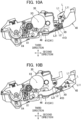
- the lock lever L is pivotally movable between a locking position indicated in Fig. 10A and an unlocking position indicated in Fig. 10B .
- the lock lever L locks the developing cartridge 30 to the drum frame 41.
- the lock lever L unlocks the developing cartridge 30 from the drum frame 41.
- the lock lever L includes an operation part L1 configured to be operated by a user, and a lifter part L2 configured to lift up the developing cartridge 30.
- the operation part L1 has a tip end L11 which is an end positioned farthest from the lock axis X9.
- the lifter part L2 has a tip end L21 which is an end positioned farthest from the lock axis X9.
- the bottom wall 41C has a hole 41D.
- the lifter part L2 of the lock lever L is in the hole 41D.
- the lifter part L2 of the lock lever L is exposed to an outside of the drum frame 41.
- the lifter part L2 is separated away from the hole 41D.
- the tip end L21 of the lifter part L2 is positioned between the developing cartridge 30 and the bottom wall 41C.
- the tip end L21 of the lifter part L2 is positioned below the lock axis X9.
- the tip end L11 of the operation part L1 is positioned above the lock axis X9.
- the tip end L21 of the lifter part L2 is positioned farther away from the bottom wall 41C when the lock lever L is at the unlocking position than when the lock lever L is at the locking position. In the state where the lock lever L is at the unlocking position, the tip end L21 of the lifter part L2 is positioned farther from the bottom wall 41C than the lock axis X9 is from the bottom wall 41C.
- the drum frame 41 has a first recessed portion 41E1, and a second recessed portion 41E2.
- first recessed portion 41E1 In a state where the developing cartridge 30 is attached to the drum frame 41, one end portion in first direction of the developing-roller shaft 32A of the developing roller 32 is positioned in the first recessed portion 41E1.
- another end portion in the first direction of the developing-roller shaft 32A of the developing roller 32 is positioned in the second recessed portion 41E2.
- the first recessed portion 41E1 is positioned at the one end portion 41A of the drum frame 41.
- the second recessed portion 41E2 is positioned at the other end portion 41B of the drum frame 41.
- the first recessed portion 41E1 and the second recessed portion 41E2 are configured to restrict movement of the developing-roller shaft 32A in the third direction.
- the developing cartridge 30 is allowed to pivotally move in the third direction about the developing axis X1.
- the developing cartridge 30 When the lock lever L is at the locking position, the developing cartridge 30 is at a contacting position where the developing cartridge 30 is in contact with the bottom wall 41C. When the lock lever L is at the unlocking position, the developing cartridge 30 is at a separated position where the developing cartridge 30 is separated away from the bottom wall 41C.
- the drum cartridge 40 further includes a pressure member P configured to press the developing roller 32 against the photosensitive drum 42.
- the pressure member P includes a first pressure member P1 and a second pressure member P2.
- the first pressure member P1 is positioned at the one end portion 41A of the drum frame 41 in the first direction.
- the second pressure member P2 is positioned at the other end portion 41B of the drum frame 41 in the first direction.
- the developing cartridge 30 includes a first counter-pressure portion 31C and a second counter-pressure portion 31D.
- the first pressure member P1 is configured to contact the first counter-pressure portion 31C.
- the second pressure member P2 is configured to contact the second counter-pressure portion 31D.
- the electrical contact surface C11 is positioned opposite the developing electrode 37 in the second direction with respect to the supply electrode surface 38A which is a part of the supply electrode 38, the electrical contact surface C11 can be located far away from the developing roller 32. Accordingly, contamination of the electrical contact surface C11 with the toner can be restrained.
- the developing electrode 37, the supply electrode 38, and the electrical contact surface C11 are positioned at the one end portion 31A of the casing 31 in the first direction, while the coupling 36 is positioned at the other end portion 31B of the casing 31 in the first direction. With this configuration, vibration of the coupling 36 is less likely to be transmitted to the developing electrode 37, the supply electrode 38, and the electrical contact surface C11.
- the electrical contact surface C11 is positioned opposite the lock lever L with respect to the casing 31 in the first direction in the state where the developing cartridge 30 is attached to the drum frame 41.
- the single circuit board C12 integrally includes the electrical contact surface C11 and the memory.
- the electrical contact surface and the memory may be configured independently of each other.
- the electrical contact surface may be electrically connected to the memory through a harness.
Landscapes
- Physics & Mathematics (AREA)
- General Physics & Mathematics (AREA)
- Engineering & Computer Science (AREA)
- Computer Vision & Pattern Recognition (AREA)
- Electrophotography Configuration And Component (AREA)
- Dry Development In Electrophotography (AREA)
Abstract
Description
- The present disclosure relates to a developing cartridge including a developing roller.
- Conventionally, as a developing cartridge, there has been known a developing cartridge that includes a casing, a developing roller, a supply roller, a developing electrode, a supply electrode, and an IC chip (see Patent Literature 1). The developing roller is rotatable about a developing axis extending in a first direction. The developing roller is positioned at one end portion of the casing in a second direction crossing the first direction. The supply roller is rotatable about a supply axis extending in the first direction. The supply roller is configured to supply toner to the developing roller. The developing electrode is configured to supply electricity to the developing roller. The supply electrode is configured to supply electricity to the supply roller. The IC chip has an electrical contact surface.
- In this technique, the electrical contact surface is positioned at one end portion of the casing in the first direction. The developing electrode and the supply electrode are positioned at another end portion of the casing in the first direction. Further, in the second direction, the electrical contact surface is at generally at the same position as the developing electrode.
- [PTL 1]
Japanese Patent Application Publication No. 2018-066973 - However, according to the conventional art, since the position of the electrical contact surface is approximately the same as the position of the developing electrode in the second direction, the electrical contact surface is positioned near the developing roller. Accordingly, it is likely that the electrical contact surface may be contaminated by toner scattering from the developing roller.
- In view of the foregoing, it is an object of the present disclosure to restrain the electrical contact surface from getting contaminated with toner.
- In order to solve the above-described problem, a developing cartridge according to the disclosure includes a casing configured to accommodate toner therein, a developing roller rotatable about a developing axis extending in a first direction and positioned at one end portion of the casing in a second direction crossing the first direction, a developing electrode electrically connected to the developing roller and positioned at one end portion of the casing in the first direction, a supply roller rotatable about a supply axis extending in the first direction and configured to supply toner to the developing roller, a supply electrode electrically connected to the supply roller and positioned at the one end portion of the casing in the first direction, and an IC chip having an electrical contact surface positioned at the one end portion of the casing in the first direction. The electrical contact surface is positioned opposite the developing electrode with respect to a part of the supply electrode in the second direction.
- With this structure, since the electrical contact surface is positioned opposite the developing electrode with respect to the part of the supply electrode in the second direction, the electrical contact surface can be positioned far away from the developing roller. The electrical contact surface can be thus restrained from being contaminated with toner.
- Further, the second direction may be perpendicular to the first direction.
- Further, the developing cartridge may further include a handle positioned at another end portion of the casing in the second direction.
- Further, the supply roller may be positioned between the developing roller and the handle in the second direction.
- Further, the developing electrode may be made of electrically conductive resin.
- Further, the supply electrode may be made of electrically conductive resin.
- Further, the developing roller may include a developing-roller shaft extending in the first direction. The developing electrode may include: a developing bearing having a developing through-hole through which the developing-roller shaft is inserted; and a developing electrode surface electrically connected to the developing bearing. The developing electrode surface may be positioned at the one end portion of the casing in the first direction.
- Further, the developing electrode surface may extend perpendicular to the first direction.
- Further, the supply roller may include a supply-roller shaft extending in the first direction. The supply electrode may include: a supply bearing having a supply through-hole through which the supply-roller shaft is inserted; and a supply electrode surface electrically connected to the supply bearing. The supply electrode surface may be positioned at the one end portion of the casing in the first direction.
- Further, the supply electrode surface may extend perpendicular to the first direction.
- Further, the electrical contact surface may be positioned opposite the developing electrode surface with respect to the supply electrode surface in the second direction.
- Further, the developing cartridge may further include an insulating member positioned between the developing electrode and the supply electrode.
- Further, the developing cartridge may further include a coupling configured to transmit a driving force to the developing roller and the supply roller, and positioned at another end portion of the casing in the first direction.
- With this structure, the developing electrode, the supply electrode, and the electrical contact surface are positioned at the one end portion of the casing in the first direction, while the coupling is positioned at the other end portion of the casing in the first direction. Hence, Vibration of the coupling to the developing electrode, the supply electrode, and the electrical contact surface is less likely to be transmitted to the developing electrode, the supply electrode, and the electrical contact surface.
- Further, the electrical contact surface may be positioned opposite the developing electrode surface with respect to the supply electrode surface in a third direction crossing the first direction and the second direction.
- Further, the third direction may be perpendicular to the first direction and the second direction.
- Further, the electrical contact surface may be movable relative to the casing.
- Further, the developing cartridge may be is attachable to and detachable from a drum frame of a drum cartridge. The drum cartridge may include a photosensitive drum rotatable about a drum axis extending in the first direction, and a lock lever configured to lock the developing cartridge to the drum frame. The electrical contact surface may be positioned opposite the lock lever in the first direction with respect to the casing in a state where the developing cartridge is attached to the drum frame.
- With this structure, when user operates the lock lever, user's fingers hardly touch the electrical contact surface, thereby suppressing contamination of the electrical contact surface.
- Further, the drum cartridge may further include a pressure member configured to press the developing roller against the photosensitive drum. The electrical contact surface is positioned opposite the lock lever in the first direction with respect to the pressure member in the state where the developing cartridge is attached to the drum frame.
- Further, the casing may have a first outer surface and a second outer surface spaced apart from the first outer surface in the first direction; and the developing electrode and the supply electrode may be positioned at the first outer surface.
- Further, a distance in the first direction between the first outer surface of the casing and the electrical contact surface may be greater than a distance in the first direction between the first outer surface of the casing and the developing electrode.
- Further, the distance in the first direction between the first outer surface of the casing and the electrical contact surface may be greater than a distance in the first direction between the first outer surface of the casing and the supply electrode.
- Further, the developing electrode may include a developing protrusion protruding in the first direction and positioned at the one end portion of the casing in the first direction. The supply electrode may include a supply protrusion protruding in the first direction and positioned at the one end portion of the casing in the first direction. The electrical contact surface may be positioned opposite the developing protrusion with respect to the supply protrusion in the second direction.
- Further, the developing protrusion may have a developing electrode surface; the supply protrusion may have a supply electrode surface; and the electrical contact surface may be positioned opposite the developing electrode surface with respect to the supply electrode surface in the second direction.
- According to the present disclosure, the electrical contact surface can be suppressed from getting contaminated with toner.
-
- [
Fig. 1] Fig. 1 is a view illustrating a structure of a process cartridge. - [
Fig. 2] Fig. 2 is a perspective view for description of a structure of one end portion of the developing cartridge in a first direction. - [
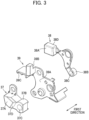
Fig. 3] Fig. 3 is an exploded perspective view illustrating a developing electrode, a supply electrode, and an insulating member. - [
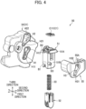
Fig. 4] Fig. 4 is an exploded perspective view of a chip holder. - [
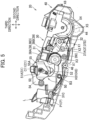
Fig. 5] Fig. 5 is a side view of the process cartridge in which a side wall at one end portion of a drum frame in the first direction is removed, and illustrating a state prior to attachment of the process cartridge to a main housing. - [
Fig. 6] Fig. 6 is a side view of the process cartridge in which the side wall at the one end portion of the drum frame in the first direction is removed, and illustrating a state where the process cartridge is attached to the main housing. - [
Fig. 7] Fig. 7 is a perspective view for description of a structure of another end portion of the developing cartridge in the first direction. - [
Fig. 8] Fig. 8 is a perspective view for description of a structure of another end portion of the process cartridge in the first direction. - [
Fig. 9] Fig. 9 is a perspective view for description of a structure of one end portion of the process cartridge in the first direction. - [
Figs. 10A, 10B] Figs. 10A and 10B are side views of the process cartridge in which a side wall at another end portion of the drum frame in the first direction is removed, andFig. 10A illustrates a state where a lock lever is at a locking position, andFig. 10B illustrates a state where the lock lever is at an unlocking position. - [
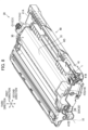
Fig. 11] Fig. 11 is a plan view illustrating the process cartridge. - Hereinafter, one embodiment of the present disclosure will be described with reference to the accompanying drawings.
- As illustrated in
Fig. 1 , animage forming apparatus 1 includes amain housing 10, and aprocess cartridge 20. Incidentally, as a matter of convenience, inFig. 1 , themain housing 10 is illustrated in a smaller size. - The
process cartridge 20 is attachable to and detachable from themain housing 10. Theprocess cartridge 20 includes a developingcartridge 30, and adrum cartridge 40. The developingcartridge 30 is attachable to and detachable from a drum frame 41 (described later) of thedrum cartridge 40. - The developing
cartridge 30 includes acasing 31, a developingroller 32, asupply roller 33, a layerthickness regulation blade 34, anagitator 35, and a handle HD. Thecasing 31 is configured to accommodate toner therein. Thecasing 31 has a first outer surface F1 (described later), and a second outer surface F2 (seeFig. 2 , described later) positioned apart from the first outer surface F1 in a first direction. - The developing
roller 32 is a roller configured to supply toner to a photosensitive drum 42 (described later). The developingroller 32 is rotatable about a developing axis X1 extending in the first direction. The developingroller 32 is positioned at one end portion of thecasing 31 in a second direction crossing the first direction. Preferably, the second direction be perpendicular to the first direction. In the present embodiment, the second direction is perpendicular to the first direction. Further, in the present embodiment, the second direction is defined as a direction along an electrical contact surface C11 (described later). - Further, in the present embodiment, a direction perpendicular to the first direction and the second direction will be defined as a third direction. Further, in the present embodiment, the third direction is assumed to be perpendicular to the electrical contact surface C11 (described later). Incidentally, the third direction may be any direction as long as the third direction crosses the first direction and the second direction.
- The developing
roller 32 includes a developing-roller shaft 32A having a columnar shape, and aroller portion 32B having a hollow cylindrical shape. The developing-roller shaft 32A is made of metal, for example. The developing-roller shaft 32A extends in the first direction. Theroller portion 32B is made of rubber, for example. Theroller portion 32B covers a part of the developing-roller shaft 32A. - The handle HD is configured to be gripped by a user. The handle HD has a U-shape (see
Fig. 2 ). The handle HD is positioned at another end portion of thecasing 31 in the second direction. - The
supply roller 33 is a roller configured to supply toner to the developingroller 32. Thesupply roller 33 is rotatable about a supply axis X2 extending in the first direction. Thesupply roller 33 is positioned between the developingroller 32 and the handle HD in the second direction. Specifically, the supply axis X2 is positioned between the developing axis X1 and the handle HD in the second direction. - The
supply roller 33 includes a supply-roller shaft 33A having a columnar shape, and aroller portion 33B having a hollow cylindrical shape. The supply-roller shaft 33A is made of metal, for example. The supply-roller shaft 33A extends in the first direction. Theroller portion 33B is made of rubber, for example. Theroller portion 33B covers a part of the supply-roller shaft 33A. Theroller portion 33B is in contact with theroller portion 32B of the developingroller 32. - The layer
thickness regulation blade 34 is a member configured to regulate a thickness of a toner layer formed on the developingroller 32. The layerthickness regulation blade 34 is in contact with theroller portion 32B of the developingroller 32. - The
agitator 35 is configured to agitate toner accommodated in thecasing 31. Also, theagitator 35 is configured to supply the toner to thesupply roller 33. Theagitator 35 is rotatable about an agitator axis X3 extending in the first direction. - The
drum cartridge 40 includes thedrum frame 41, thephotosensitive drum 42, acharger 43, atransfer roller 44, a cleaningroller 45, a conveyingroller 46, and a lock lever L. Thephotosensitive drum 42 is rotatable about a drum axis X4 extending in the first direction. - The
charger 43 is configured to charge thephotosensitive drum 42. Thecharger 43 is a Scorotron charger positioned away from thephotosensitive drum 42. - The
transfer roller 44 is a roller configured to transfer the toner on thephotosensitive drum 42 to a non-illustrated sheet. Thetransfer roller 44 is rotatable about a transfer axis X5 extending in the first direction. Thetransfer roller 44 is in contact with thephotosensitive drum 42. Thephotosensitive drum 42 is positioned between thecharger 43 and thetransfer roller 44 in the third direction. - The cleaning
roller 45 is a roller configured to remove the toner deposited on thephotosensitive drum 42. The cleaningroller 45 is rotatable about a cleaning axis X6 extending in the first direction. The cleaningroller 45 is in contact with thephotosensitive drum 42. - The conveying
roller 46 is a roller configured to convey the sheet toward thephotosensitive drum 42. The conveyingroller 46 is rotatable about a conveying axis X7 extending in the first direction. - As illustrated in
Fig. 2 , the developingcartridge 30 further includes an IC chip C1, a developingelectrode 37, asupply electrode 38, an insulatingmember 39, and achip holder 50. The IC chip C1, the developingelectrode 37, thesupply electrode 38, and thechip holder 50 are positioned at oneend portion 31A of thecasing 31 in the first direction. In other words, the IC chip C1, the developingelectrode 37, thesupply electrode 38, and thechip holder 50 are positioned at the first outer surface F1 of thecasing 31. - The IC chip C1 is configured to store development information relating to the developing
cartridge 30. The development information may be a residual amount of toner in the developingcartridge 30, and a service life of the developingroller 32, for example. The IC chip C1 includes the electrical contact surface C11, and a circuit board C12 incorporating a memory storing the development information. The electrical contact surface C11 is electrically connected to the memory. The electrical contact surface C11 is positioned at the oneend portion 31A of thecasing 31 in the first direction. In a state where theprocess cartridge 20 is attached to themain housing 10, the electrical contact surface C11 contacts a main contact 13 (described later, seeFig. 6 ). - The developing
electrode 37 is electrically connected to the developingroller 32. The developingelectrode 37 is made of electrically conductive resin. The developingelectrode 37 includes a developingprotrusion 37D having a developingelectrode surface 37A, and a developingbearing 37B. The developingprotrusion 37D protrudes in the first direction. The developingelectrode surface 37A is positioned at a tip end of the developingprotrusion 37D in the first direction. The developingelectrode surface 37A is configured to contact a developing main electrode (not illustrated) of themain housing 10. The developingelectrode surface 37A extends perpendicular to the first direction. The developingelectrode surface 37A is electrically connected to the developingbearing 37B. The developingprotrusion 37D is positioned at the oneend portion 31A of thecasing 31 in the first direction. In other words, the developingprotrusion 37D is positioned at the first outer surface F1 of thecasing 31. The developingelectrode surface 37A is positioned at the oneend portion 31A of thecasing 31 in the first direction. In other words, the developingelectrode surface 37A is positioned at the first outer surface F1 of thecasing 31. The developingbearing 37B has a developing through-hole 37C (seeFig. 3 ) through which the developing-roller shaft 32A is inserted. - The
supply electrode 38 is electrically connected to the supply roller 33 (seeFig. 1 ). Thesupply electrode 38 is made of electrically conductive resin. As illustrated inFig. 3 , thesupply electrode 38 includes asupply protrusion 38D having asupply electrode surface 38A, and asupply bearing 38B. Thesupply protrusion 38D protrudes in the first direction. Thesupply electrode surface 38A is positioned at a tip end of thesupply protrusion 38D in the first direction. Thesupply electrode surface 38A is configured to contact a supply main electrode (not illustrated) of themain housing 10. Thesupply electrode surface 38A extends perpendicular to the first direction. Thesupply electrode surface 38A is electrically connected to thesupply bearing 38B. Thesupply protrusion 38D is positioned at the oneend portion 31A of thecasing 31 in the first direction. In other words, thesupply protrusion 38D is positioned at the first outer surface F1 of thecasing 31. The supply electrode surface 3 8A is positioned at the oneend portion 31A of thecasing 31 in the first direction. In other words, thesupply electrode surface 38A is positioned at the first outer surface F1 of thecasing 31. Thesupply bearing 38B has a supply through-hole 38C through which the supply-roller shaft 33A (seeFig. 1 ) is inserted. - The insulating
member 39 is made of insulation resin, for example. The insulatingmember 39 is positioned between the developingelectrode 37 and thesupply electrode 38. Specifically, the insulatingmember 39 includes a plate-shapedpart 39A, afirst wall part 39B, and asecond wall part 39C. The plate-shapedpart 39A is positioned between the developingelectrode 37 and thesupply electrode 38 in the first direction. Thefirst wall part 39B and thesecond wall part 39C extend from the plate-shapedpart 39A in a direction away from thecasing 31. As illustrated inFig. 5 , thefirst wall part 39B is positioned on a side of thesupply electrode surface 38A in the second direction, the side being closer to the developing axis X1. Thesecond wall part 39C is positioned on a side of thesupply electrode surface 38A in the third direction, the side being closer the developing axis X1. A part of thefirst wall part 39B and a part of thesecond wall part 39C are positioned between the developingelectrode surface 37A and thesupply electrode surface 38A in a direction perpendicular to the first direction. - The electrical contact surface C11 is positioned opposite the developing
electrode 37 with respect to thesupply electrode surface 38A in the second direction. In other words, the electrical contact surface C11 is positioned opposite the developingelectrode 37 with respect to thesupply electrode surface 38A, which is a part of thesupply electrode 38, in the second direction. Stated differently, the electrical contact surface C11 is positioned opposite the developingprotrusion 37D with respect to thesupply protrusion 38D in the second direction. - Further, the electrical contact surface C11 is positioned opposite the developing
electrode surface 37A with respect to thesupply electrode surface 38A in the third direction. In other words, the electrical contact surface C11 is positioned opposite the developingelectrode 37 with respect to thesupply electrode surface 38A, which is the part of thesupply electrode 38, in the third direction. Stated differently, the electrical contact surface C11 is positioned opposite the developingprotrusion 37D with respect to thesupply protrusion 38D in the third direction. The electrical contact surface C11 extends perpendicular to the third direction. - As illustrated in
Fig. 11 , a distance in the first direction between the first outer surface F1 of thecasing 31 and the electrical contact surface C11 is greater than a distance in the first direction between the first outer surface F1 of thecasing 31 and the developingelectrode 37. In other words, the distance in the first direction between the first outer surface F1 of thecasing 31 and the electrical contact surface C11 is greater than a distance in the first direction between the first outer surface F1 of thecasing 31 and the developingelectrode surface 37A. - The distance in the first direction between the first outer surface F1 of the
casing 31 and the electrical contact surface C11 is greater than a distance in the first direction between the first outer surface F1 of thecasing 31 and thesupply electrode 38. In other words, the distance in the first direction between the first outer surface F1 of thecasing 31 and the electrical contact surface C11 is greater than a distance in the first direction between the first outer surface F1 of thecasing 31 and thesupply electrode surface 38A. - The distance in the first direction between the first outer surface F1 of the
casing 31 and the electrical contact surface C11 is greater than a distance in the first direction between the first outer surface F1 of thecasing 31 and the insulatingmember 39. - The
chip holder 50 holds the IC chip C1 such that the electrical contact surface C11 is movable relative to thecasing 31. As illustrated inFig. 4 , thechip holder 50 includes aholder 51, an advancing/retractingmember 52, aspring 53, afirst cover 54, and asecond cover 55. Theholder 51 is a member holding the IC chip C1. Further, theholder 51 supports the advancing/retractingmember 52 such that the advancing/retractingmember 52 is movable in the third direction. - The
holder 51 includes aseat part 51A, atubular part 51B, a first boss B1, a second boss B2, and a third boss B3. Theseat part 51A is a part retaining the IC chip C1. Theseat part 51A protrudes from thetubular part 51B toward thesecond cover 55 in the first direction. - The
tubular part 51B has a hollow rectangular cylindrical shape. Thetubular part 51B extends from theseat part 51A in a direction away from the IC chip C1. The first boss B1 and the second boss B2 protrude from thetubular part 51B toward thefirst cover 54 in the first direction. The third boss B3 protrudes from thetubular part 51B toward thesecond cover 55 in the first direction. - The
spring 53 is positioned between theholder 51 and the advancing/retractingmember 52. Thespring 53 is a coil spring. Thespring 53 urges the advancing/retractingmember 52 in a direction away from the IC chip C1. - The
first cover 54 is positioned at the firstouter surface 31A of thecasing 31. Thefirst cover 54 has a first elongated slot H1 and a second elongated slot H2. The first boss B1 is inserted in the first elongated slot H1. The second boss B2 is inserted in the second elongated slot H2. - The
second cover 55 is attached to thefirst cover 54. Thetubular part 51B of theholder 51 is positioned between thefirst cover 54 and thesecond cover 55 in the first direction in a state where thesecond cover 55 is attached to thefirst cover 54. Thesecond cover 55 has a third elongated slot H3. The third boss B3 is inserted in the third elongated slot H3. Further, thesecond cover 55 has aseat surface 55A configured to retain theseat part 51A. - The first elongated slot H1, the second elongated slot H2, and the third elongated slot H3 are holes elongated in the third direction. The first elongated slot H1 has one end portion H11 and another end portion H12 spaced away from the one end portion H11 in the third direction. The one end portion H11 has a length in the second direction that is shorter than a length in the second direction of the other end portion H12. The one end portion H11 is positioned below the other end portion H12 in the state where the
process cartridge 20 is attached to themain housing 10. The one end portion H11 is configured to restrict movement of the first boss B1 in the second direction. The other end portion H12 is configured to allow the first boss B1 to move in the second direction. - The second elongated slot H2 has one end portion H21 and another end portion H22 spaced away from the one end portion H21 in the third direction. The one end portion H21 has a length in the second direction that is shorter than a length in the second direction of the other end portion H22. The one end portion H21 is positioned below the other end portion H22 in the state where the
process cartridge 20 is attached to themain housing 10. The one end portion H21 is configured to restrict movement of the second boss B2 in the second direction. The other end portion H22 is configured to allow the second boss B2 to move in the second direction. - The third elongated slot H3 has one end portion H31 and another end portion H32 spaced away from the one end portion H31 in the third direction. The one end portion H31 has a length in the second direction that is shorter than a length in the second direction of the other end portion H32. The one end portion H31 is positioned below the other end portion H32 in the state where the
process cartridge 20 is attached to themain housing 10. The one end portion H31 is configured to restrict movement of the third boss B3 in the second direction. The other end portion H32 is configured to allow the third boss B3 to move in the second direction. - With the
chip holder 50 constructed as described above, the electrical contact surface C11 is movable between a first position indicated inFig. 5 and a second position indicated inFig. 6 . As illustrated inFig. 5 , the electrical contact surface C11 is located at the first position in a state prior to attachment of theprocess cartridge 20 to themain housing 10. In a state where the electrical contact surface C11 is at the first position, theholder 51 is held by thefirst cover 54 and thesecond cover 55. - Specifically, the
seat part 51A of theholder 51 is in contact with theseat surface 55A of thesecond cover 55 in the state where the electrical contact surface C11 is at the first position. Further, in the state where the electrical contact surface C11 is at the first position, the third boss B3 is in contact with the one end portion H31 of the third elongated slot H3. Although not illustrated, the first boss B1 is in contact with the one end portion H11 of the first elongated slot H1 and the second boss B2 is in contact with the one end portion H21 of the second elongated slot H2 in the state where the electrical contact surface C11 is at the first position. - As illustrated in
Fig. 6 , the electrical contact surface C11 is positioned farther away from the developing axis X1 in the third direction when the electrical contact surface C11 is at the second position than when the electrical contact surface C11 is at the first position. Further, the electrical contact surface C11 is positioned closer to the developing axis X1 in the second direction when the electrical contact surface C11 is at the second position than when the electrical contact surface C11 is at the first position. The electrical contact surface C11 is at the second position in the state where theprocess cartridge 20 is attached to themain housing 10. Themain housing 10 includes afirst guide 11, asecond guide 12, and themain contact 13. Thefirst guide 11 is a guide configured to contact a lower end of the advancing/retractingmember 52 to guide the advancing/retractingmember 52. Thesecond guide 12 is a guide configured to contact an upper end of theholder 51 to guide theholder 51. Themain contact 13 is a contact configured to contact the electrical contact surface C11 of the IC chip C1. Themain contact 13 is configured to electrically connect the IC chip C1 to a controller (not illustrated). Incidentally, inFig. 6 , for the sake of convenience, the IC chip C1 and themain contact 13 are depicted as being separated away from each other. - In the state where the electrical contact surface C11 is at the second position, the
holder 51 is held by thefirst guide 11 of themain housing 10 through the advancing/retractingmember 52 and thespring 53. Further, in the state where the electrical contact surface C11 is at the second position, theseat part 51A of theholder 51 is separated upward from theseat surface 55A of thesecond cover 55. Further, the third boss B3 is separated away from an inner surface of the third elongated slot H3 in the state where the electrical contact surface C11 is at the second position. Although not illustrated in the drawings, the first boss B1 is separated away from an inner surface of the first elongated slot H1 in the state where the electrical contact surface C11 is at the second position. Further, the second boss B2 is separated away from an inner surface of the second elongated slot H2 in the state where the electrical contact surface C11 is at the second position. In the state where the electrical contact surface C11 is at the second position, the IC chip C1 is urged toward themain contact 13 by an urging force of thespring 53. The electrical contact surface C11 is in contact with themain contact 13 in the state where the electrical contact surface C11 is at the second position. - In the state where the
process cartridge 20 is attached to themain housing 10, the third direction is parallel to an up-down direction. In the state where theprocess cartridge 20 is attached to themain housing 10, the electrical contact surface C11 is positioned above the developing axis X1. - As illustrated in
Fig.7 , the developingcartridge 30 further includes acoupling 36. Thecoupling 36 is positioned at anotherend portion 31B of thecasing 31 in the first direction. In other words, thecoupling 36 is positioned at the second outer surface F2 of thecasing 31. - The
coupling 36 is configured to transmit a driving force to the developingroller 32, thesupply roller 33, and theagitator 35. Thecoupling 36 is rotatable about a coupling axis X8 extending in the first direction. Thecoupling 36 is configured to receive the driving force from a drive source (not illustrated) of themain housing 10. The driving force transmitted from the drive source to thecoupling 36 is configured to be transmitted to the developingroller 32, thesupply roller 33, and theagitator 35 through non-illustrated gears. - As illustrated in
Fig. 8 , the lock lever L is configured to lock the developingcartridge 30 to thedrum frame 41. Thedrum frame 41 has oneend portion 41A and anotherend portion 41B in the first direction. The lock lever L is positioned at theother end portion 41B of thedrum frame 41 in the first direction. In the state where the developingcartridge 30 is attached to thedrum flame 41, the electrical contact surface C11 is positioned opposite the lock lever L with respect to thecasing 31 in the first direction. - As illustrated in
Fig. 9 , the developingcartridge 30 further includes a gear cover GC. The gear cover GC is a cover that covers the gears for driving the developingroller 32, and the like. The gear cover GC is positioned at theother end 31B of thecasing 31 in the first direction. The lock lever L contacts the gear cover GC. As illustrated inFigs. 10A and 10B , thedrum frame 41 includes abottom wall 41C. Thebottom wall 41C is positioned below the developingcartridge 30 in the state where theprocess cartridge 20 is attached to themain housing 10. The lock lever L is configured to lift up a part of the developingcartridge 30 in a direction away from thebottom wall 41C of thedrum frame 41. - The lock lever L is pivotally movable about a lock axis X9 extending in the first direction. The lock lever L is pivotally movable between a locking position indicated in
Fig. 10A and an unlocking position indicated inFig. 10B . At the locking position, the lock lever L locks the developingcartridge 30 to thedrum frame 41. At the unlocking position, the lock lever L unlocks the developingcartridge 30 from thedrum frame 41. - The lock lever L includes an operation part L1 configured to be operated by a user, and a lifter part L2 configured to lift up the developing
cartridge 30. The operation part L1 has a tip end L11 which is an end positioned farthest from the lock axis X9. The lifter part L2 has a tip end L21 which is an end positioned farthest from the lock axis X9. - The
bottom wall 41C has ahole 41D. In a state where the lock lever L is at the locking position, the lifter part L2 of the lock lever L is in thehole 41D. In the state where the lock lever L is at the locking position, the lifter part L2 of the lock lever L is exposed to an outside of thedrum frame 41. In a state where the lock lever L is at the unlocking position, the lifter part L2 is separated away from thehole 41D. - In the state where the lock lever L is at the locking position, the tip end L21 of the lifter part L2 is positioned between the developing
cartridge 30 and thebottom wall 41C. In the state where theprocess cartridge 20 is attached to themain housing 10, the tip end L21 of the lifter part L2 is positioned below the lock axis X9. In the state where theprocess cartridge 20 is attached to themain housing 10, the tip end L11 of the operation part L1 is positioned above the lock axis X9. - The tip end L21 of the lifter part L2 is positioned farther away from the
bottom wall 41C when the lock lever L is at the unlocking position than when the lock lever L is at the locking position. In the state where the lock lever L is at the unlocking position, the tip end L21 of the lifter part L2 is positioned farther from thebottom wall 41C than the lock axis X9 is from thebottom wall 41C. - As illustrated in
Figs. 8 and9 , thedrum frame 41 has a first recessed portion 41E1, and a second recessed portion 41E2. In a state where the developingcartridge 30 is attached to thedrum frame 41, one end portion in first direction of the developing-roller shaft 32A of the developingroller 32 is positioned in the first recessed portion 41E1. In the state where the developingcartridge 30 is attached to thedrum frame 41, another end portion in the first direction of the developing-roller shaft 32A of the developingroller 32 is positioned in the second recessed portion 41E2. The first recessed portion 41E1 is positioned at the oneend portion 41A of thedrum frame 41. The second recessed portion 41E2 is positioned at theother end portion 41B of thedrum frame 41. The first recessed portion 41E1 and the second recessed portion 41E2 are configured to restrict movement of the developing-roller shaft 32A in the third direction. With this structure, as illustrated inFigs. 10A and 10B , the developingcartridge 30 is allowed to pivotally move in the third direction about the developing axis X1. - When the lock lever L is at the locking position, the developing
cartridge 30 is at a contacting position where the developingcartridge 30 is in contact with thebottom wall 41C. When the lock lever L is at the unlocking position, the developingcartridge 30 is at a separated position where the developingcartridge 30 is separated away from thebottom wall 41C. - As illustrated in
Fig. 11 , thedrum cartridge 40 further includes a pressure member P configured to press the developingroller 32 against thephotosensitive drum 42. The pressure member P includes a first pressure member P1 and a second pressure member P2. The first pressure member P1 is positioned at the oneend portion 41A of thedrum frame 41 in the first direction. The second pressure member P2 is positioned at theother end portion 41B of thedrum frame 41 in the first direction. - In the state where the developing
cartridge 30 is attached to thedrum frame 41, the electrical contact surface C11 is positioned opposite the lock lever L in the first direction with respect to the first pressure member P1 and the second pressure member P2. The developingcartridge 30 includes a firstcounter-pressure portion 31C and a secondcounter-pressure portion 31D. The first pressure member P1 is configured to contact the firstcounter-pressure portion 31C. The second pressure member P2 is configured to contact the secondcounter-pressure portion 31D. - According to the above-described structure, the following technical advantages can be obtained in the present embodiment.
- As illustrated in
Fig. 5 , since the electrical contact surface C11 is positioned opposite the developingelectrode 37 in the second direction with respect to thesupply electrode surface 38A which is a part of thesupply electrode 38, the electrical contact surface C11 can be located far away from the developingroller 32. Accordingly, contamination of the electrical contact surface C11 with the toner can be restrained. - As illustrated in
Figs. 8 and9 , the developingelectrode 37, thesupply electrode 38, and the electrical contact surface C11 are positioned at the oneend portion 31A of thecasing 31 in the first direction, while thecoupling 36 is positioned at theother end portion 31B of thecasing 31 in the first direction. With this configuration, vibration of thecoupling 36 is less likely to be transmitted to the developingelectrode 37, thesupply electrode 38, and the electrical contact surface C11. - The electrical contact surface C11 is positioned opposite the lock lever L with respect to the
casing 31 in the first direction in the state where the developingcartridge 30 is attached to thedrum frame 41. With this structure, when the user operates the lock lever L, user's fingers hardly touch the electrical contact surface C11, thereby suppressing contamination of the electrical contact surface C11. - Incidentally, the present disclosure is not limited to the above-described embodiment, but various modifications as illustrated below may be made.
- According to the above-described embodiment, the single circuit board C12 integrally includes the electrical contact surface C11 and the memory. However, the electrical contact surface and the memory may be configured independently of each other. Incidentally, in this case, the electrical contact surface may be electrically connected to the memory through a harness.
- Each part and component described in the depicted embodiment and the modifications may be combined together arbitrarily.
-
- 30: developing cartridge
- 31: casing
- 31A: one end portion
- 32: developing roller
- 33: supply roller
- 37: developing electrode
- 38: supply electrode
- 38A: supply electrode surface
- C1: IC chip
- C11: electrical contact surface
- X1: developing axis
- X2: supply axis
Claims (23)
- A developing cartridge comprising:a casing configured to accommodate toner therein;a developing roller rotatable about a developing axis extending in a first direction, the developing roller being positioned at one end portion of the casing in a second direction crossing the first direction;a developing electrode electrically connected to the developing roller, the developing electrode being positioned at one end portion of the casing in the first direction;a supply roller rotatable about a supply axis extending in the first direction, the supply roller being configured to supply toner to the developing roller;a supply electrode electrically connected to the supply roller, the supply electrode being positioned at the one end portion of the casing in the first direction; andan IC chip having an electrical contact surface positioned at the one end portion of the casing in the first direction,wherein the electrical contact surface is positioned opposite the developing electrode with respect to a part of the supply electrode in the second direction.
- The developing cartridge according to claim 1,
wherein the second direction is perpendicular to the first direction. - The developing cartridge according to claim 1 or 2, further comprising a handle positioned at another end portion of the casing in the second direction.
- The developing cartridge according to claim 3,
wherein the supply roller is positioned between the developing roller and the handle in the second direction. - The developing cartridge according to any one of claims 1 through 4,
wherein the developing electrode is made of electrically conductive resin. - The developing cartridge according to any one of claims 1 through 5,
wherein the supply electrode is made of electrically conductive resin. - The developing cartridge according to any one of claims 1 through 6,wherein the developing roller includes a developing-roller shaft extending in the first direction,wherein the developing electrode includes:a developing bearing having a developing through-hole through which the developing-roller shaft is inserted; anda developing electrode surface electrically connected to the developing bearing, andwherein the developing electrode surface is positioned at the one end portion of the casing in the first direction.
- The developing cartridge according to claim 7,
wherein the developing electrode surface extends perpendicular to the first direction. - The developing cartridge according to claim 7 or 8,wherein the supply roller includes a supply-roller shaft extending in the first direction,wherein the supply electrode includes:a supply bearing having a supply through-hole through which the supply-roller shaft is inserted; anda supply electrode surface electrically connected to the supply bearing, andwherein the supply electrode surface is positioned at the one end portion of the casing in the first direction.
- The developing cartridge according to claim 9,
wherein the supply electrode surface extends perpendicular to the first direction. - The developing cartridge according to claim 9 or 10,
wherein the electrical contact surface is positioned opposite the developing electrode surface with respect to the supply electrode surface in the second direction. - The developing cartridge according to any one of claims 9 through 11, further comprising an insulating member positioned between the developing electrode and the supply electrode.
- The developing cartridge according to any one of claims 9 through 12,
wherein the electrical contact surface is positioned opposite the developing electrode surface with respect to the supply electrode surface in a third direction crossing the first direction and the second direction. - The developing cartridge according to claim 13,
wherein the third direction is perpendicular to the first direction and the second direction. - The developing cartridge according to any one of claims 1 through 14, further comprising a coupling configured to transmit a driving force to the developing roller and the supply roller, the coupling being positioned at another end portion of the casing in the first direction.
- The developing cartridge according to any one of claims 1 through 15,
wherein the electrical contact surface is movable relative to the casing. - The developing cartridge according to any one of claims 1 through 16,wherein the developing cartridge is attachable to and detachable from a drum frame of a drum cartridge, the drum cartridge including:a photosensitive drum rotatable about a drum axis extending in the first direction; anda lock lever configured to lock the developing cartridge to the drum frame,wherein the electrical contact surface is positioned opposite the lock lever in the first direction with respect to the casing in a state where the developing cartridge is attached to the drum frame.
- The developing cartridge according to claim 17,wherein the drum cartridge further includes a pressure member configured to press the developing roller against the photosensitive drum, andwherein the electrical contact surface is positioned opposite the lock lever in the first direction with respect to the pressure member in the state where the developing cartridge is attached to the drum frame.
- The developing cartridge according to any one of claims 1 through 18,wherein the casing has a first outer surface and a second outer surface spaced apart from the first outer surface in the first direction, andwherein the developing electrode and the supply electrode are positioned at the first outer surface.
- The developing cartridge according to claim 19,
wherein a distance in the first direction between the first outer surface of the casing and the electrical contact surface is greater than a distance in the first direction between the first outer surface of the casing and the developing electrode. - The developing cartridge according to claim 20,
wherein the distance in the first direction between the first outer surface of the casing and the electrical contact surface is greater than a distance in the first direction between the first outer surface of the casing and the supply electrode. - The developing cartridge according to any one of claims 1 through 21,wherein the developing electrode includes a developing protrusion protruding in the first direction and positioned at the one end portion of the casing in the first direction,wherein the supply electrode includes a supply protrusion protruding in the first direction and positioned at the one end portion of the casing in the first direction, andwherein the electrical contact surface is positioned opposite the developing protrusion with respect to the supply protrusion in the second direction.
- The developing cartridge according to claim 22,wherein the developing protrusion has a developing electrode surface,wherein the supply protrusion has a supply electrode surface, andwherein the electrical contact surface is positioned opposite the developing electrode surface with respect to the supply electrode surface in the second direction.
Applications Claiming Priority (2)
| Application Number | Priority Date | Filing Date | Title |
|---|---|---|---|
| JP2021029023A JP7666017B2 (en) | 2021-02-25 | 2021-02-25 | Developing cartridge |
| PCT/JP2022/006566 WO2022181465A1 (en) | 2021-02-25 | 2022-02-18 | Development cartridge |
Publications (3)
| Publication Number | Publication Date |
|---|---|
| EP4300211A1 true EP4300211A1 (en) | 2024-01-03 |
| EP4300211A4 EP4300211A4 (en) | 2025-02-19 |
| EP4300211B1 EP4300211B1 (en) | 2026-05-13 |
Family
ID=83048966
Family Applications (1)
| Application Number | Title | Priority Date | Filing Date |
|---|---|---|---|
| EP22759501.4A Active EP4300211B1 (en) | 2021-02-25 | 2022-02-18 | Developing cartridge |
Country Status (5)
| Country | Link |
|---|---|
| US (2) | US12140882B2 (en) |
| EP (1) | EP4300211B1 (en) |
| JP (1) | JP7666017B2 (en) |
| CN (1) | CN116848474A (en) |
| WO (1) | WO2022181465A1 (en) |
Families Citing this family (3)
| Publication number | Priority date | Publication date | Assignee | Title |
|---|---|---|---|---|
| JP6729118B2 (en) * | 2016-07-15 | 2020-07-22 | ブラザー工業株式会社 | Developer cartridge |
| JP7666017B2 (en) * | 2021-02-25 | 2025-04-22 | ブラザー工業株式会社 | Developing cartridge |
| CN117784563B (en) * | 2024-02-27 | 2024-05-03 | 珠海中凯打印机耗材有限公司 | An integrated separation toner cartridge structure |
Family Cites Families (17)
| Publication number | Priority date | Publication date | Assignee | Title |
|---|---|---|---|---|
| JP2008203566A (en) * | 2007-02-20 | 2008-09-04 | Brother Ind Ltd | Image forming apparatus, process cartridge, and developing cartridge |
| US8005392B2 (en) | 2007-02-20 | 2011-08-23 | Brother Kogyo Kabushiki Kaisha | Image forming device with pressing members, process cartridge, and developer cartridge |
| JP4985029B2 (en) * | 2007-03-29 | 2012-07-25 | ブラザー工業株式会社 | Image forming apparatus and process cartridge |
| JP5370137B2 (en) * | 2009-12-25 | 2013-12-18 | ブラザー工業株式会社 | cartridge |
| JP5861581B2 (en) * | 2012-07-09 | 2016-02-16 | ブラザー工業株式会社 | Process cartridge and image forming apparatus |
| CN103969989B (en) * | 2013-01-24 | 2017-07-14 | 爱思打印解决方案有限公司 | Electrophotographic image forming apparatus and developing cartridge |
| US9195165B2 (en) * | 2014-01-06 | 2015-11-24 | Brother Kogyo Kabushiki Kaisha | Developing cartridge and process cartridge |
| JP6582972B2 (en) | 2015-12-25 | 2019-10-02 | ブラザー工業株式会社 | Developer cartridge |
| JP6604197B2 (en) * | 2015-12-25 | 2019-11-13 | ブラザー工業株式会社 | Developer cartridge |
| JP6693302B2 (en) | 2016-06-30 | 2020-05-13 | ブラザー工業株式会社 | Developer cartridge |
| JP6729118B2 (en) * | 2016-07-15 | 2020-07-22 | ブラザー工業株式会社 | Developer cartridge |
| JP6880712B2 (en) * | 2016-10-14 | 2021-06-02 | ブラザー工業株式会社 | Drum cartridge and development cartridge |
| JP6733567B2 (en) * | 2017-01-31 | 2020-08-05 | ブラザー工業株式会社 | Developer cartridge |
| JP6922265B2 (en) * | 2017-03-07 | 2021-08-18 | ブラザー工業株式会社 | Drum cartridge and process cartridge |
| JP6822279B2 (en) | 2017-03-31 | 2021-01-27 | ブラザー工業株式会社 | Develop cartridges, process cartridges, and image forming equipment |
| JP2018194660A (en) * | 2017-05-17 | 2018-12-06 | ブラザー工業株式会社 | Image forming apparatus |
| JP7666017B2 (en) * | 2021-02-25 | 2025-04-22 | ブラザー工業株式会社 | Developing cartridge |
-
2021
- 2021-02-25 JP JP2021029023A patent/JP7666017B2/en active Active
-
2022
- 2022-02-18 EP EP22759501.4A patent/EP4300211B1/en active Active
- 2022-02-18 CN CN202280011410.9A patent/CN116848474A/en active Pending
- 2022-02-18 WO PCT/JP2022/006566 patent/WO2022181465A1/en not_active Ceased
-
2023
- 2023-07-18 US US18/354,091 patent/US12140882B2/en active Active
-
2024
- 2024-10-11 US US18/912,918 patent/US20250036043A1/en active Pending
Also Published As
| Publication number | Publication date |
|---|---|
| JP7666017B2 (en) | 2025-04-22 |
| US20250036043A1 (en) | 2025-01-30 |
| EP4300211A4 (en) | 2025-02-19 |
| CN116848474A (en) | 2023-10-03 |
| EP4300211B1 (en) | 2026-05-13 |
| WO2022181465A1 (en) | 2022-09-01 |
| US20230359137A1 (en) | 2023-11-09 |
| US12140882B2 (en) | 2024-11-12 |
| JP2022130069A (en) | 2022-09-06 |
Similar Documents
| Publication | Publication Date | Title |
|---|---|---|
| EP4300211B1 (en) | Developing cartridge | |
| US11567446B2 (en) | Process cartridge configured of developing cartridge including electrical contact surface, and drum cartridge including electrical contact surface and lock lever | |
| US9568856B2 (en) | Developing cartridge | |
| US9136744B2 (en) | Electric motor with reduced axial footprint | |
| JP2018004907A (en) | Image developing cartridge | |
| JP7512652B2 (en) | Cartridges and how to recycle them | |
| CN213023955U (en) | Drum Cartridges and Image Forming Equipment | |
| US12164263B2 (en) | Toner cartridge including memory holder cover having pawl engaged with hook of gear cover | |
| JP2024087576A (en) | Terminal Unit | |
| JP2020160224A (en) | Drum cartridge and development cartridge | |
| CN110235063B (en) | Developing box | |
| JP2020160223A (en) | Developing cartridge | |
| JP2018010243A (en) | Drum cartridge | |
| CN105843010B (en) | Developing box | |
| WO2022211126A1 (en) | Toner cartridge and drum cartridge | |
| JP2020160222A (en) | Developing cartridge | |
| US11054788B1 (en) | Conductive structure and process cartridge having the same | |
| EP4597228A1 (en) | Drum cartridge | |
| JP7722105B2 (en) | drum cartridge | |
| US20260010114A1 (en) | Developing cartridge | |
| US11892798B2 (en) | Image forming apparatus capable of making toner cartridge completely attached to drum cartridge during attachment of drum cartridge to housing | |
| CN223808638U (en) | Drum assembly and developing box | |
| US20260010096A1 (en) | Developing cartridge | |
| CN219872125U (en) | Developing box | |
| JP4670294B2 (en) | Vehicle door handle device |
Legal Events
| Date | Code | Title | Description |
|---|---|---|---|
| STAA | Information on the status of an ep patent application or granted ep patent |
Free format text: STATUS: THE INTERNATIONAL PUBLICATION HAS BEEN MADE |
|
| PUAI | Public reference made under article 153(3) epc to a published international application that has entered the european phase |
Free format text: ORIGINAL CODE: 0009012 |
|
| STAA | Information on the status of an ep patent application or granted ep patent |
Free format text: STATUS: REQUEST FOR EXAMINATION WAS MADE |
|
| 17P | Request for examination filed |
Effective date: 20230719 |
|
| AK | Designated contracting states |
Kind code of ref document: A1 Designated state(s): AL AT BE BG CH CY CZ DE DK EE ES FI FR GB GR HR HU IE IS IT LI LT LU LV MC MK MT NL NO PL PT RO RS SE SI SK SM TR |
|
| P01 | Opt-out of the competence of the unified patent court (upc) registered |
Effective date: 20240110 |
|
| DAV | Request for validation of the european patent (deleted) | ||
| DAX | Request for extension of the european patent (deleted) | ||
| A4 | Supplementary search report drawn up and despatched |
Effective date: 20250120 |
|
| RIC1 | Information provided on ipc code assigned before grant |
Ipc: G03G 15/08 20060101ALI20250114BHEP Ipc: G03G 21/18 20060101AFI20250114BHEP |
|
| GRAP | Despatch of communication of intention to grant a patent |
Free format text: ORIGINAL CODE: EPIDOSNIGR1 |
|
| STAA | Information on the status of an ep patent application or granted ep patent |
Free format text: STATUS: GRANT OF PATENT IS INTENDED |
|
| INTG | Intention to grant announced |
Effective date: 20260107 |
|
| GRAS | Grant fee paid |
Free format text: ORIGINAL CODE: EPIDOSNIGR3 |
|
| GRAA | (expected) grant |
Free format text: ORIGINAL CODE: 0009210 |
|
| STAA | Information on the status of an ep patent application or granted ep patent |
Free format text: STATUS: THE PATENT HAS BEEN GRANTED |
|
| AK | Designated contracting states |
Kind code of ref document: B1 Designated state(s): AL AT BE BG CH CY CZ DE DK EE ES FI FR GB GR HR HU IE IS IT LI LT LU LV MC MK MT NL NO PL PT RO RS SE SI SK SM TR |
|
| REG | Reference to a national code |
Ref country code: CH Ref legal event code: F10 Free format text: ST27 STATUS EVENT CODE: U-0-0-F10-F00 (AS PROVIDED BY THE NATIONAL OFFICE) Effective date: 20260513 |