EP4300195A1 - Image forming apparatus - Google Patents
Image forming apparatus Download PDFInfo
- Publication number
- EP4300195A1 EP4300195A1 EP23163539.2A EP23163539A EP4300195A1 EP 4300195 A1 EP4300195 A1 EP 4300195A1 EP 23163539 A EP23163539 A EP 23163539A EP 4300195 A1 EP4300195 A1 EP 4300195A1
- Authority
- EP
- European Patent Office
- Prior art keywords
- medium
- jig
- unit
- transfer
- image
- Prior art date
- Legal status (The legal status is an assumption and is not a legal conclusion. Google has not performed a legal analysis and makes no representation as to the accuracy of the status listed.)
- Granted
Links
Images


Classifications
-
- G—PHYSICS
- G03—PHOTOGRAPHY; CINEMATOGRAPHY; ANALOGOUS TECHNIQUES USING WAVES OTHER THAN OPTICAL WAVES; ELECTROGRAPHY; HOLOGRAPHY
- G03G—ELECTROGRAPHY; ELECTROPHOTOGRAPHY; MAGNETOGRAPHY
- G03G15/00—Apparatus for electrographic processes using a charge pattern
- G03G15/65—Apparatus which relate to the handling of copy material
- G03G15/6529—Transporting
-
- G—PHYSICS
- G03—PHOTOGRAPHY; CINEMATOGRAPHY; ANALOGOUS TECHNIQUES USING WAVES OTHER THAN OPTICAL WAVES; ELECTROGRAPHY; HOLOGRAPHY
- G03G—ELECTROGRAPHY; ELECTROPHOTOGRAPHY; MAGNETOGRAPHY
- G03G21/00—Arrangements not provided for by groups G03G13/00 - G03G19/00, e.g. cleaning, elimination of residual charge
- G03G21/16—Mechanical means for facilitating the maintenance of the apparatus, e.g. modular arrangements
- G03G21/18—Mechanical means for facilitating the maintenance of the apparatus, e.g. modular arrangements using a processing cartridge, whereby the process cartridge comprises at least two image processing means in a single unit
- G03G21/1803—Arrangements or disposition of the complete process cartridge or parts thereof
- G03G21/1814—Details of parts of process cartridge, e.g. for charging, transfer, cleaning, developing
-
- H—ELECTRICITY
- H04—ELECTRIC COMMUNICATION TECHNIQUE
- H04N—PICTORIAL COMMUNICATION, e.g. TELEVISION
- H04N1/00—Scanning, transmission or reproduction of documents or the like, e.g. facsimile transmission; Details thereof
- H04N1/00519—Constructional details not otherwise provided for, e.g. housings, covers
- H04N1/00559—Mounting or support of components or elements
-
- G—PHYSICS
- G03—PHOTOGRAPHY; CINEMATOGRAPHY; ANALOGOUS TECHNIQUES USING WAVES OTHER THAN OPTICAL WAVES; ELECTROGRAPHY; HOLOGRAPHY
- G03G—ELECTROGRAPHY; ELECTROPHOTOGRAPHY; MAGNETOGRAPHY
- G03G15/00—Apparatus for electrographic processes using a charge pattern
- G03G15/01—Apparatus for electrographic processes using a charge pattern for producing multicoloured copies
- G03G15/0105—Details of unit
- G03G15/0131—Details of unit for transferring a pattern to a second base
-
- G—PHYSICS
- G03—PHOTOGRAPHY; CINEMATOGRAPHY; ANALOGOUS TECHNIQUES USING WAVES OTHER THAN OPTICAL WAVES; ELECTROGRAPHY; HOLOGRAPHY
- G03G—ELECTROGRAPHY; ELECTROPHOTOGRAPHY; MAGNETOGRAPHY
- G03G15/00—Apparatus for electrographic processes using a charge pattern
- G03G15/01—Apparatus for electrographic processes using a charge pattern for producing multicoloured copies
- G03G15/0105—Details of unit
- G03G15/0131—Details of unit for transferring a pattern to a second base
- G03G15/0136—Details of unit for transferring a pattern to a second base transfer member separable from recording member or vice versa, mode switching
-
- G—PHYSICS
- G03—PHOTOGRAPHY; CINEMATOGRAPHY; ANALOGOUS TECHNIQUES USING WAVES OTHER THAN OPTICAL WAVES; ELECTROGRAPHY; HOLOGRAPHY
- G03G—ELECTROGRAPHY; ELECTROPHOTOGRAPHY; MAGNETOGRAPHY
- G03G15/00—Apparatus for electrographic processes using a charge pattern
- G03G15/14—Apparatus for electrographic processes using a charge pattern for transferring a pattern to a second base
- G03G15/16—Apparatus for electrographic processes using a charge pattern for transferring a pattern to a second base of a toner pattern, e.g. a powder pattern, e.g. magnetic transfer
- G03G15/1625—Apparatus for electrographic processes using a charge pattern for transferring a pattern to a second base of a toner pattern, e.g. a powder pattern, e.g. magnetic transfer on a base other than paper
-
- G—PHYSICS
- G03—PHOTOGRAPHY; CINEMATOGRAPHY; ANALOGOUS TECHNIQUES USING WAVES OTHER THAN OPTICAL WAVES; ELECTROGRAPHY; HOLOGRAPHY
- G03G—ELECTROGRAPHY; ELECTROPHOTOGRAPHY; MAGNETOGRAPHY
- G03G15/00—Apparatus for electrographic processes using a charge pattern
- G03G15/14—Apparatus for electrographic processes using a charge pattern for transferring a pattern to a second base
- G03G15/16—Apparatus for electrographic processes using a charge pattern for transferring a pattern to a second base of a toner pattern, e.g. a powder pattern, e.g. magnetic transfer
- G03G15/163—Apparatus for electrographic processes using a charge pattern for transferring a pattern to a second base of a toner pattern, e.g. a powder pattern, e.g. magnetic transfer using the force produced by an electrostatic transfer field formed between the second base and the electrographic recording member, e.g. transfer through an air gap
- G03G15/1635—Apparatus for electrographic processes using a charge pattern for transferring a pattern to a second base of a toner pattern, e.g. a powder pattern, e.g. magnetic transfer using the force produced by an electrostatic transfer field formed between the second base and the electrographic recording member, e.g. transfer through an air gap the field being produced by laying down an electrostatic charge behind the base or the recording member, e.g. by a corona device
- G03G15/165—Arrangements for supporting or transporting the second base in the transfer area, e.g. guides
-
- G—PHYSICS
- G03—PHOTOGRAPHY; CINEMATOGRAPHY; ANALOGOUS TECHNIQUES USING WAVES OTHER THAN OPTICAL WAVES; ELECTROGRAPHY; HOLOGRAPHY
- G03G—ELECTROGRAPHY; ELECTROPHOTOGRAPHY; MAGNETOGRAPHY
- G03G15/00—Apparatus for electrographic processes using a charge pattern
- G03G15/14—Apparatus for electrographic processes using a charge pattern for transferring a pattern to a second base
- G03G15/16—Apparatus for electrographic processes using a charge pattern for transferring a pattern to a second base of a toner pattern, e.g. a powder pattern, e.g. magnetic transfer
- G03G15/163—Apparatus for electrographic processes using a charge pattern for transferring a pattern to a second base of a toner pattern, e.g. a powder pattern, e.g. magnetic transfer using the force produced by an electrostatic transfer field formed between the second base and the electrographic recording member, e.g. transfer through an air gap
- G03G15/1635—Apparatus for electrographic processes using a charge pattern for transferring a pattern to a second base of a toner pattern, e.g. a powder pattern, e.g. magnetic transfer using the force produced by an electrostatic transfer field formed between the second base and the electrographic recording member, e.g. transfer through an air gap the field being produced by laying down an electrostatic charge behind the base or the recording member, e.g. by a corona device
- G03G15/165—Arrangements for supporting or transporting the second base in the transfer area, e.g. guides
- G03G15/1655—Arrangements for supporting or transporting the second base in the transfer area, e.g. guides comprising a rotatable holding member to which the second base is attached or attracted, e.g. screen transfer holding drum
- G03G15/166—Arrangements for supporting or transporting the second base in the transfer area, e.g. guides comprising a rotatable holding member to which the second base is attached or attracted, e.g. screen transfer holding drum with means for conditioning the holding member, e.g. cleaning
-
- G—PHYSICS
- G03—PHOTOGRAPHY; CINEMATOGRAPHY; ANALOGOUS TECHNIQUES USING WAVES OTHER THAN OPTICAL WAVES; ELECTROGRAPHY; HOLOGRAPHY
- G03G—ELECTROGRAPHY; ELECTROPHOTOGRAPHY; MAGNETOGRAPHY
- G03G15/00—Apparatus for electrographic processes using a charge pattern
- G03G15/65—Apparatus which relate to the handling of copy material
- G03G15/6588—Apparatus which relate to the handling of copy material characterised by the copy material, e.g. postcards, large copies, multi-layered materials, coloured sheet material
-
- G—PHYSICS
- G03—PHOTOGRAPHY; CINEMATOGRAPHY; ANALOGOUS TECHNIQUES USING WAVES OTHER THAN OPTICAL WAVES; ELECTROGRAPHY; HOLOGRAPHY
- G03G—ELECTROGRAPHY; ELECTROPHOTOGRAPHY; MAGNETOGRAPHY
- G03G21/00—Arrangements not provided for by groups G03G13/00 - G03G19/00, e.g. cleaning, elimination of residual charge
- G03G21/16—Mechanical means for facilitating the maintenance of the apparatus, e.g. modular arrangements
- G03G21/18—Mechanical means for facilitating the maintenance of the apparatus, e.g. modular arrangements using a processing cartridge, whereby the process cartridge comprises at least two image processing means in a single unit
- G03G21/1839—Means for handling the process cartridge in the apparatus body
- G03G21/1867—Means for handling the process cartridge in the apparatus body for electrically connecting the process cartridge to the apparatus, electrical connectors, power supply
-
- G—PHYSICS
- G03—PHOTOGRAPHY; CINEMATOGRAPHY; ANALOGOUS TECHNIQUES USING WAVES OTHER THAN OPTICAL WAVES; ELECTROGRAPHY; HOLOGRAPHY
- G03G—ELECTROGRAPHY; ELECTROPHOTOGRAPHY; MAGNETOGRAPHY
- G03G15/00—Apparatus for electrographic processes using a charge pattern
- G03G15/20—Apparatus for electrographic processes using a charge pattern for fixing, e.g. by using heat
- G03G15/2003—Apparatus for electrographic processes using a charge pattern for fixing, e.g. by using heat using heat
- G03G15/2007—Apparatus for electrographic processes using a charge pattern for fixing, e.g. by using heat using heat using radiant heat, e.g. infrared lamps, microwave heaters
- G03G15/201—Apparatus for electrographic processes using a charge pattern for fixing, e.g. by using heat using heat using radiant heat, e.g. infrared lamps, microwave heaters of high intensity and short duration, i.e. flash fusing
-
- G—PHYSICS
- G03—PHOTOGRAPHY; CINEMATOGRAPHY; ANALOGOUS TECHNIQUES USING WAVES OTHER THAN OPTICAL WAVES; ELECTROGRAPHY; HOLOGRAPHY
- G03G—ELECTROGRAPHY; ELECTROPHOTOGRAPHY; MAGNETOGRAPHY
- G03G2215/00—Apparatus for electrophotographic processes
- G03G2215/00362—Apparatus for electrophotographic processes relating to the copy medium handling
- G03G2215/00367—The feeding path segment where particular handling of the copy medium occurs, segments being adjacent and non-overlapping. Each segment is identified by the most downstream point in the segment, so that for instance the segment labelled "Fixing device" is referring to the path between the "Transfer device" and the "Fixing device"
- G03G2215/00371—General use over the entire feeding path
-
- G—PHYSICS
- G03—PHOTOGRAPHY; CINEMATOGRAPHY; ANALOGOUS TECHNIQUES USING WAVES OTHER THAN OPTICAL WAVES; ELECTROGRAPHY; HOLOGRAPHY
- G03G—ELECTROGRAPHY; ELECTROPHOTOGRAPHY; MAGNETOGRAPHY
- G03G2215/00—Apparatus for electrophotographic processes
- G03G2215/00362—Apparatus for electrophotographic processes relating to the copy medium handling
- G03G2215/00367—The feeding path segment where particular handling of the copy medium occurs, segments being adjacent and non-overlapping. Each segment is identified by the most downstream point in the segment, so that for instance the segment labelled "Fixing device" is referring to the path between the "Transfer device" and the "Fixing device"
- G03G2215/00379—Copy medium holder
-
- G—PHYSICS
- G03—PHOTOGRAPHY; CINEMATOGRAPHY; ANALOGOUS TECHNIQUES USING WAVES OTHER THAN OPTICAL WAVES; ELECTROGRAPHY; HOLOGRAPHY
- G03G—ELECTROGRAPHY; ELECTROPHOTOGRAPHY; MAGNETOGRAPHY
- G03G2215/00—Apparatus for electrophotographic processes
- G03G2215/00362—Apparatus for electrophotographic processes relating to the copy medium handling
- G03G2215/00443—Copy medium
- G03G2215/00523—Other special types, e.g. tabbed
-
- G—PHYSICS
- G03—PHOTOGRAPHY; CINEMATOGRAPHY; ANALOGOUS TECHNIQUES USING WAVES OTHER THAN OPTICAL WAVES; ELECTROGRAPHY; HOLOGRAPHY
- G03G—ELECTROGRAPHY; ELECTROPHOTOGRAPHY; MAGNETOGRAPHY
- G03G2215/00—Apparatus for electrophotographic processes
- G03G2215/00362—Apparatus for electrophotographic processes relating to the copy medium handling
- G03G2215/00535—Stable handling of copy medium
- G03G2215/00687—Handling details
- G03G2215/00708—Cleaning of sheet or feeding structures
-
- G—PHYSICS
- G03—PHOTOGRAPHY; CINEMATOGRAPHY; ANALOGOUS TECHNIQUES USING WAVES OTHER THAN OPTICAL WAVES; ELECTROGRAPHY; HOLOGRAPHY
- G03G—ELECTROGRAPHY; ELECTROPHOTOGRAPHY; MAGNETOGRAPHY
- G03G2215/00—Apparatus for electrophotographic processes
- G03G2215/00362—Apparatus for electrophotographic processes relating to the copy medium handling
- G03G2215/00919—Special copy medium handling apparatus
-
- G—PHYSICS
- G03—PHOTOGRAPHY; CINEMATOGRAPHY; ANALOGOUS TECHNIQUES USING WAVES OTHER THAN OPTICAL WAVES; ELECTROGRAPHY; HOLOGRAPHY
- G03G—ELECTROGRAPHY; ELECTROPHOTOGRAPHY; MAGNETOGRAPHY
- G03G2215/00—Apparatus for electrophotographic processes
- G03G2215/16—Transferring device, details
- G03G2215/1604—Main transfer electrode
- G03G2215/1623—Transfer belt
-
- H—ELECTRICITY
- H04—ELECTRIC COMMUNICATION TECHNIQUE
- H04N—PICTORIAL COMMUNICATION, e.g. TELEVISION
- H04N2201/00—Indexing scheme relating to scanning, transmission or reproduction of documents or the like, and to details thereof
Definitions
- the present disclosure relates to an image forming apparatus.
- Japanese Patent No. 3292954 discloses a printer that forms an image on an image formation surface of a disc transported by a transport device.
- a toner image given to a transfer belt is electrically transferred onto the image formation surface of the disc by bringing an electrode of a transfer device into contact with the image formation surface and supplying an electric charge.
- Some image forming apparatuses bring a transfer unit into contact with an image formation surface of a recording medium transported by a transport unit and thereby transfer an image formed with particles such as toner onto the recording medium.
- the transfer unit transfers the image formed with particles onto the recording medium by an electric field formed between the transfer unit and the recording medium.
- a support unit that supports a recording medium from a perspective of making misregistration of the recording medium less likely to occur due to a shock caused when the transfer unit makes contact with the recording medium.
- particles such as toner may be undesirably attached from the transfer unit to the support unit by an electric field between the transfer unit and the support unit.
- an image forming apparatus including: a transport unit that transports a recording medium; a transfer unit that transfers an image formed with particles onto an image formation surface of the recording medium transported by the transport unit by an electric field formed between the transfer unit and the image formation surface by making contact with the image formation surface; and a support unit that supports the recording medium, is transported to the transfer unit together with the recording medium by the transport unit, and is not directly conductive with the transfer unit.
- the image forming apparatus is configured such that the support unit does not make contact with the transfer unit.
- the image forming apparatus is configured such that the support unit supports a side surface of the recording medium and has a height lower than a height of the image formation surface of the recording medium.
- the image forming apparatus is configured such that the support unit makes contact with the transfer unit and has, on a portion that makes contact with the transfer unit, a non-conductive layer having lower electric conductivity than the image formation surface of the recording medium.
- the image forming apparatus is configured such that a portion of the support unit that makes contact with the recording medium has electric conductivity, and the support unit is conductive with the image formation surface of the recording medium by making contact with the recording medium.
- the image forming apparatus is configured to further include a power source that applies a voltage for forming the electric field, wherein the power source applies no voltage during a period for which the transfer unit and the image formation surface of the recording medium are not in contact with each other.
- the image forming apparatus is configured such that the support unit makes contact with the transfer unit before the transfer unit and the image formation surface of the recording medium make contact with each other; and the power source applies no voltage before the transfer unit and the image formation surface of the recording medium make contact with each other.
- the image forming apparatus is configured to further include a cleaning unit that cleans the support unit by making contact with the support unit that has passed through the transfer unit.
- particles are less likely to be attached to the support unit than in a case where the support unit that supports the recording medium and the transfer unit are directly conductive with each other.
- particles are less likely to be attached to the support unit than in a case where the support unit makes contact with the transfer unit.
- particles are less likely to be attached to the support unit than in a case where the height of the support unit is equal to or higher than the height of the image formation surface of the recording medium.
- particles are less likely to be attached to the support unit than in a case where the support unit does not have a non-conductive portion on the portion that makes contact with the transfer unit.
- an electric field can be formed between the transfer unit and the image formation surface of the recording medium by using the support unit.
- particles are less likely to be attached to the support unit than in a case where a voltage is applied during a period for which the transfer unit and the image formation surface of the recording medium are not in contact with each other.
- particles are less likely to be attached to a front side of the support unit than in a case where a voltage is applied before the transfer unit and the image formation surface of the recording medium make contact with each other.
- particles attached to the support unit that has passed through the transfer unit can be reduced as compared with a case where the cleaning unit is not provided.
- An image forming apparatus is an image forming apparatus employing digital printing.
- an electrophotographic system, an inkjet system, and the like are known as digital printing systems, the electrophotographic system is assumed in the present exemplary embodiment.
- a transfer unit and a medium are brought into contact with each other when an image is transferred onto the medium.
- any of media having various thicknesses and shapes such as metal, glass, and tile is assumed as an object on which an image is to be printed.
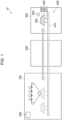
- Fig. 1 illustrates a configuration of an image forming apparatus to which the present exemplary embodiment is applied.
- the image forming apparatus 10 includes a transfer unit 100, a fixing unit 200, a medium attaching detaching unit 300, and a transport mechanism 400.
- the image forming apparatus 10 includes a controller 600 having one or more processors, which are computing units, a memory serving as a working region in data processing, and a storage device that holds a program and data.
- the controller 600 is a single controller that controls operation of the whole image forming apparatus 10 in this example, the controller 600 may be individually provided in units such as the transfer unit 100, the fixing unit 200, and the transport mechanism 400.
- the transfer unit 100 is a unit that transfers an image formed with particles such as toner onto a recording medium 500 (hereinafter simply referred to as a medium 500).
- the fixing unit 200 is a unit that fixes, on a surface of the medium 500, an image transferred by the transfer unit 100 by heating the medium 500.
- the medium attaching detaching unit 300 is a unit in which a user of the image forming apparatus 10 attaches the medium 500 to an attachment table (described later) provided in the transport mechanism 400.
- the transport mechanism 400 is provided across the transfer unit 100, the fixing unit 200, and the medium attaching detaching unit 300, and transports the medium 500 on which an image is to be printed to the units 100, 200, and 300 as indicated by the arrow in Fig. 1 .
- Fig. 2 illustrates a configuration of the transfer unit 100.
- the transfer unit 100 forms an image with charged particles and transfers the image onto the medium 500 by generating an electric field.
- the transfer unit 100 includes a developing device 110, a first transfer roll 120, and an intermediate transfer belt 131.
- the intermediate transfer belt 131 is tensioned between the developing device 110 and a position where an image is transferred onto the medium 500 by rollers 132 and 133 and a backup roll 140.
- the transfer unit 100 includes a cleaning device 150 for removing particles attached to the intermediate transfer belt 131.
- the transfer unit 100 includes a power source 160 that applies a predetermined voltage to the backup roll 140.
- the developing device 110 is a unit that forms, on a photoreceptor, an electrostatic latent image of an image to be transferred and develops the image by attaching charged particles to the electrostatic latent image on the photoreceptor.
- an existing device used in an electrophotographic image forming apparatus can be used.
- Fig. 2 illustrates an example of a configuration employed in a case where color image formation processing is performed by using four colors, that is, three colors: yellow, magenta, and cyan, and an additional one color: black.
- the developing device 110 is provided for each of these colors, and the developing devices 110 for yellow, magenta, cyan, and black are given alphabets (color signs) Y, M, C, and K indicative of the colors in Fig. 2 .
- the suffixes are omitted in a case where the colors of the developing devices 110 need not be distinguished although the suffixes Y, M, C, and K are given to the reference signs in a case where the colors are distinguished.
- the first transfer roll 120 is a unit used to transfer (first transfer) an image formed by the developing device 110 onto the intermediate transfer belt 131.
- the first transfer roll 120 is disposed so as to face the photoreceptor of the developing device 110, and the intermediate transfer belt 131 is located between the developing device 110 and the first transfer roll 120.
- the first transfer roll 120 is provided corresponding to each of the developing devices 110Y, 110M, 110C, and 110K.
- the first transfer rolls 120 corresponding to the developing devices 110Y, 110M, 110C, and 110K of the respective colors are given alphabets (color signs) Y, M, C, and K indicative of the colors.
- the suffixes are omitted in a case where the colors of the first transfer rolls 120 need not be distinguished although the suffixes Y, M, C, and K are given to the reference signs in a case where the colors are distinguished.
- the intermediate transfer belt 131, the rollers 132 and 133, and the backup roll 140 are units used to transfer an image formed by the developing device 110 onto the medium 500.
- the intermediate transfer belt 131 rotates in a direction indicated by the arrows in Fig. 2 (a counterclockwise direction in the example illustrated in Fig. 2 ) while being suspended around the rollers 132 and 133 and the backup roll 140 in a tensioned state.
- the rollers 132 and 133 is(are) a roller(s) that is(are) driven to rotate, and the intermediate transfer belt 131 is pulled by rotation of this(these) roller(s). In this way, the intermediate transfer belt 131 rotates.
- An outer surface of the intermediate transfer belt 131 in the example of the configuration in Fig. 2 is a surface (hereinafter referred to as a "transfer surface") on which an image is held.
- An image is transferred from the photoreceptor of the developing device 110 onto the transfer surface of the intermediate transfer belt 131 when the intermediate transfer belt 131 passes between the developing device 110 and the first transfer roll 120.
- images of the respective colors: yellow (Y), magenta (M), cyan (C), and black (K) are superimposed on the transfer surface by the developing devices 110Y, 110M, 110C, and 110K and the first transfer rolls 120Y, 120M, 120C, and 120K, and thus a multi-color image is formed.
- the backup roll 140 transfers (second transfer) the image onto the medium 500 by bringing the transfer surface of the intermediate transfer belt 131 into contact with the medium 500.
- a predetermined voltage is applied to the backup roll 140 by the power source 160 when the image is transferred. This generates an electric field (hereinafter referred to as a "transfer electric field") in a range including the backup roll 140 and the medium 500, thereby transferring the image formed with charged particles from the intermediate transfer belt 131 onto the medium 500.
- a transfer electric field an electric field in a range including the backup roll 140 and the medium 500, thereby transferring the image formed with charged particles from the intermediate transfer belt 131 onto the medium 500.
- the medium 500 is a conductor such as a metal
- an electric current flows through the medium 500 itself, and therefore an image is transferred onto a surface of the medium 500 by generating a transfer electric field.
- the medium 500 is not a conductor
- no electric current flows through the medium 500, and therefore an image cannot be transferred in this state.
- an electric current is passed through the medium 500 by taking a measure such as forming a layer made of an electrically conductive material (hereinafter referred to as an "electrically conductive layer”) in advance in at least a region on the surface of the medium 500 where an image is to be formed.
- a procedure of transfer of an image by the intermediate transfer belt 131 is described.
- images of the respective colors: yellow (Y), magenta (M), cyan (C), and black (K) are sequentially superimposed on the transfer surface (outer surface in Fig. 2 ) of the intermediate transfer belt 131 by the developing devices 110Y, 110M, 110C, and 110K and the first transfer rolls 120Y, 120M, 120C, and 120K, and thus a multi-color image is formed.
- the intermediate transfer belt 131 further rotates, the image formed on the transfer surface of the intermediate transfer belt 131 reaches a position (hereinafter referred to as a "transfer position") where the intermediate transfer belt 131 makes contact with the medium 500.
- a voltage is applied to the backup roll 140. This generates a transfer electric field, thereby transferring the image from the intermediate transfer belt 131 onto the medium 500.
- the cleaning device 150 is a unit that removes particles attached to the transfer surface of the intermediate transfer belt 131.
- the cleaning device 150 is provided at a position on a downstream side relative to the transfer position and an upstream side relative to the developing device 110Y and the first transfer roll 120Y in a direction in which the intermediate transfer belt 131 rotates. With this configuration, particles remaining on the transfer surface of the intermediate transfer belt 131 are removed by the cleaning device 150 after the image is transferred from the intermediate transfer belt 131 onto the medium 500. In a next operation cycle, an image is newly transferred (first transfer) onto the transfer surface from which particles have been removed.
- the medium 500 can have various thicknesses and shapes.
- the medium 500 directly placed on a transport path constituted by a belt and a roller is transported, it is difficult to bring the intermediate transfer belt 131 into contact with the medium 500 in a predetermined relationship since a height of the medium 500 relative to the transport path varies at the transfer position of the transfer unit 100 in a case where a thickness and a shape of the medium 500 vary.
- the transport mechanism 400 has the attachment table 420 having a height adjuster and transports the medium 500 placed on the attachment table 420 together with the attachment table 420.
- the transport mechanism 400 includes the transport rail 410 that specifies a transport path for the medium 500 and the attachment table 420 that moves on the transport rail 410 (see Fig. 2 ).
- the attachment table 420 includes a leg part 421 attached to the transport rail 410 and a table part 422 on which the medium 500 is to be placed. Furthermore, a jig 430 that holds the medium 500 on the table part 422 is attached to the table part 422.
- the transport rail 410 is disposed so as to extend from the medium attaching detaching unit 300 to the transfer unit 100 while passing the fixing unit 200.
- An end portion of the transport rail 410 on a medium attaching detaching unit 300 side is the transport start position and the transport end position.
- the attachment table 420 is transported leftward in Fig. 1 from the transport start position of the medium attaching detaching unit 300, and an image is transferred onto the medium 500 in the transfer unit 100. Then, the attachment table 420 is transported rightward in Fig. 1 , and reaches the transport end position of the medium attaching detaching unit 300 after the image is fixed on the medium 500 in the fixing unit 200.
- the leg part 421 is attached to the transport rail 410 and moves on the transport rail 410.
- a mechanism for moving the leg part 421 on the transport rail 410 is not limited in particular.
- the leg part 421 may be provided with a driving device so as to be movable on its own or the transport rail 410 may be provided with a unit that pulls the leg part 421.
- the leg part 421 has a height controller that controls a height of the table part 422.
- a configuration of the height controller is not limited in particular.
- the table part 422 may be moved up and down by rack and pinion and a drive motor.
- the height of the table part 422 may be controlled by manually operating a gear that is linked with the height of the table part 422.
- an input interface for input to a controller of the drive motor may be prepared, and an operator of the image forming apparatus 10 may manually input and set height data by using the input interface.
- the height of the medium 500 attached to the attachment table 420 may be automatically detected by using a sensor, and the drive motor may be controlled so that the medium 500 is located at an appropriate height.
- the table part 422 is a table that is attached to the leg part 421 and on which the medium 500 is placed with the jig 430 interposed therebetween.
- the table part 422 is provided with a fastener (not illustrated) for positioning the jig 430. Any jigs 430 compatible with this fastener can be positioned and attached to the table part 422 irrespective of shapes thereof.
- the table part 422 is attached so as to float up and sink down with respect to the leg part 421 in accordance with a pressure applied from an upper side.
- the configuration in which the table part 422 floats up and sinks down is, for example, realized by interposing an elastic body at a portion where the table part 422 and the leg part 421 are joined.
- the table part 422 is made of an electrically conductive material. Furthermore, the table part 422 is in contact with a grounding member (not illustrated) and is connected to ground with the grounding member interposed therebetween.
- the jig 430 is an example of a support unit and is a device that holds the medium 500 and is attached to the table part 422.
- a portion of the jig 430 attached to the table part 422 has a shape and a structure compatible with the fastener of the table part 422.
- the jig 430 has a shape for holding the medium 500. Therefore, media 500 having various shapes and sizes can be placed on the attachment table 420 by preparing jigs 430 compatible with the shapes and sizes of the media 500.
- the jig 430 is made of an electrically conductive material. Furthermore, the portion of the jig 430 attached to the table part 422 is conductive with the table part 422. Furthermore, the jig 430 supports the medium 500 so as to be conductive with a surface (an image formation surface, which will be described later) of the medium 500 including a region where an image is to be formed. In this way, the image formation surface of the medium 500 supported by the jig 430 is connected to ground with the jig 430 and the table part 422 interposed therebetween.
- the image forming apparatus 10 has the transport mechanism 400 configured as above and therefore can print an image on any of the media 500 having various shapes and sizes.
- the height of the table part 422 is controlled in order to prevent a strong shock from being caused by contact of the medium 500 with the intermediate transfer belt 131 of the transfer unit 100 or prevent failure to bring the medium 500 into contact with the intermediate transfer belt 131 when an image is transferred onto the medium 500.
- Figs. 3A to 3C illustrate operation of the transport mechanism 400 before start of image formation by the transfer unit 100.
- Fig. 3A illustrates how the height is controlled
- Fig. 3B illustrates a state where the attachment table 420 has retreated to a preparation position after the height control
- Fig. 3C illustrates a state where the transfer unit 100 starts transfer of an image.
- the medium 500 held by the jig 430 is placed on the attachment table 420 at the transport start position of the medium attaching detaching unit 300. Then, the medium 500 is lowered to a height at which the medium 500 does not make contact with the intermediate transfer belt 131 of the transfer unit 100 by the height controller of the attachment table 420, and then the attachment table 420 on which the medium 500 is placed is moved to a position below the transfer position of the transfer unit 100.
- the height of the attachment table 420 is controlled so that the medium 500 makes contact with the intermediate transfer belt 131 with a strength appropriate for transfer of the image at the transfer position (arrow a in Fig. 3A ).
- a transfer execution height information on an appropriate height (hereinafter referred to as a "transfer execution height") thus obtained is held, for example, in the memory of the controller 600 (see Fig. 1 ).
- the attachment table 420 is lowered to a height where the medium 500 does not make contact with the intermediate transfer belt 131 and moves to the preparation position for transfer operation (arrow b in Fig. 3A ).
- the attachment table 420 moves to the preparation position, the height of the attachment table 420 is adjusted to the transfer execution height on the basis of the information obtained in the height control. Then, the attachment table 420 moves to the transfer position (arrow c in Fig. 3B ), and transfer of the image starts when the medium 500 makes contact with the intermediate transfer belt 131 at the transfer position ( Fig. 3C ).
- the image is fixed in the fixing unit 200.
- an image is formed on any of the media 500 having various thicknesses and shapes, and therefore the fixing processing is performed by a non-contact-type device.
- the fixing unit 200 melts particles forming the image transferred onto the medium 500 by heating the particles and thereby fixes the particles on the surface of the medium 500.
- Figs. 4A and 4B illustrate a configuration and operation of the fixing unit 200.
- Fig. 4A illustrates a state where openings of the fixing unit 200 are closed
- Fig. 4B illustrates a state where the openings of the fixing unit 200 are opened.
- the fixing unit 200 includes a carry-in opening 201, which is an opening through which the medium 500 is carried into the fixing unit 200, and a carry-out opening 202, which is an opening through which the medium 500 is carried out of the fixing unit 200.
- the carry-in opening 201 and the carry-out opening 202 of the fixing unit 200 are provided with an opening and closing member and are configured to be opened when the medium 500 is carried into or out of the fixing unit 200 and be closed when the fixing processing is performed.
- the fixing unit 200 includes a heat source 210 for thermal fixation.
- the heat source 210 can be, for example, any of various existing heat sources such as a halogen lamp, a ceramic heater, and an infrared lamp. Instead of the heat source 210, a device that heats particles forming the image by emitting infrared laser may be used.
- the fixing unit 200 according to the present exemplary embodiment is provided with a member that can cover the heat source 210, and is configured so that the heat source 210 is exposed when the fixing processing is performed.
- roll-up shutters 220 and 230 are provided as the opening and closing members of the carry-in opening 201 and the carry-out opening 202.
- the shutters 220 and 230 are closed (see Fig. 4A ) except when the medium 500 is carried into and out of the fixing unit 200 and thereby prevent a decrease in internal temperature.
- the shutter 220 of the carry-in opening 201 opens when the medium 500 is carried into the fixing unit 200
- the shutter 230 of the carry-out opening 202 opens when the medium 500 is carried out of the fixing unit 200 (see Fig. 4B ).
- a roll-up shutter 240 is provided as the covering member that covers the heat source 210.
- the shutter 240 closes in a case where the shutter 220 of the carry-in opening 201 and/or the shutter 230 of the carry-out opening 202 open(s) (see Fig. 4B ). This may keep a decrease in temperature of the heat source 210 small even in a case where the carry-in opening 201 and/or the carry-out opening 202 open(s) and the internal temperature decreases.
- a state where both of the shutter 220 of the carry-in opening 201 and the shutter 230 of the carry-out opening 202 are opened is illustrated for convenience of description.
- the shutter 230 of the carry-out opening 202 remains closed when the medium 500 is carried into the fixing unit 200
- the shutter 220 of the carry-in opening 201 remains closed when the medium 500 is carried out of the fixing unit 200. This keeps a decrease in internal temperature small.
- the shutters 220, 230, and 240 illustrated in Figs. 4A and 4B are an example of the opening and closing members of the carry-in opening 201 and the carry-out opening 202 and the covering member of the heat source 210.
- the opening and closing members and covering member are not limited to the above configuration, as long as the opening and closing members and covering member keep a decrease in internal temperature of the fixing unit 200 and temperature of the heat source 210 small.
- an opening and closing door may be provided instead of the shutters 220, 230, and 240 illustrated in Figs. 4A and 4B .
- a curtain made of a heat insulating material or air curtain may be used to prevent leakage of internal air.
- the medium attaching detaching unit 300 is a unit that is located at the transport start position and the transport end position, which are an end portion of the transport rail 410.
- the jig 430 is attached and detached to and from the attachment table 420 or the medium 500 is attached and detached to and from the jig 430 attached to the attachment table 420.
- the medium attaching detaching unit 300 includes a cleaning device 350 for removing particles attached to an upper surface 431 (see Fig. 5 , which will be described later) of the jig 430.
- the cleaning device 350 has, for example, a brush, a web, or the like that makes contact with the upper surface 431 of the jig 430.
- the attachment table 420 on which the jig 430 holding the medium 500 is placed moves to the transport end position of the medium attaching detaching unit 300.
- the medium 500 is removed from the jig 430 attached to the attachment table 420.
- the particles attached to the upper surface 431 of the jig 430 are removed by the cleaning device 350.
- an image formed with particles is transferred from the transfer surface of the intermediate transfer belt 131 onto the medium 500 by bringing the transfer surface of the intermediate transfer belt 131 into contact with the medium 500 held by the jig 430.
- the transfer surface of the intermediate transfer belt 131 and the upper surface 431 of the jig 430 sometimes make contact with each other, and particles are sometimes attached from the intermediate transfer belt 131 to the upper surface 431 of the jig 430.
- the particles are sometimes attached to a new medium 500 and smear the new medium 500 when the new medium 500 is placed on the jig 430 after image formation operation on the medium 500 is finished.
- the particles attached to the jig 430 are removed by the cleaning device 350, and therefore it is less likely that the particles are attached to and smear the medium 500 placed on the jig 430.
- the transfer unit 100 when the attachment table 420 on which the medium 500 is placed moves to the transfer position, the backup roll 140 and the image formation surface of the medium 500 make contact with each other with the intermediate transfer belt 131 interposed therebetween. This forms a transfer electric field between the backup roll 140 and the image formation surface of the medium 500, thereby transferring an image formed with particles from the transfer surface of the intermediate transfer belt 131 onto the image formation surface of the medium 500.
- the jig 430 holding the medium 500 has electric conductivity and is connected to ground with the table part 422 interposed therebetween. Accordingly, if the intermediate transfer belt 131 makes contact with the jig 430 and the backup roll 140 and the jig 430 become directly conductive with each other with the intermediate transfer belt 131 interposed therebetween when the attachment table 420 moves to the transfer position, particles are sometimes attached from the transfer surface of the intermediate transfer belt 131, for example, onto the upper surface 431 of the jig 430 due to an electric field between the backup roll 140 and the jig 430.
- a state where the jig 430 and members that constitute the transfer unit 100 such as the intermediate transfer belt 131 and the backup roll 140 are directly conductive with each other means a state where the jig 430 is conductive with members that constitute the transfer unit 100 by directly making contact with or facing the members without the medium 500 interposed therebetween.
- the jig 430 is not directly conductive with the intermediate transfer belt 131 and the backup roll 140 although the jig 430 is conductive with the intermediate transfer belt 131 and the backup roll 140 with the medium 500 interposed therebetween.
- the jig 430 supports the medium 500 so as not to make contact with the intermediate transfer belt 131, and thereby the jig 430 is prevented from becoming directly conductive with the intermediate transfer belt 131 and the backup roll 140. In this way, particles are less likely to be attached from the intermediate transfer belt 131 onto the jig 430.
- the transport direction means a transport direction (a direction indicated by arrow c in Fig. 3B ) in which the attachment table 420, the medium 500 attached to the attachment table 420, or the like is transported from the preparation position to the transport end position by passing through the transfer position.
- Fig. 5 is a perspective view illustrating the jig 430 and the medium 500 held by the jig 430 to which the first exemplary embodiment is applied.
- Figs. 6A and 6B illustrate a relationship between (i) the jig 430 and the medium 500 to which the first exemplary embodiment is applied and (ii) the intermediate transfer belt 131 and the backup roll 140
- Fig. 6A illustrates an example using the jig 430 illustrated in Fig. 5
- Fig. 6B illustrates an example using a modification of the jig 430.
- Figs. 6A and 6B are cross-sectional views of the jig 430 and the medium 500 taken along the transport direction at a central part in a width direction thereof.
- the medium 500 has a front surface 510 and a rear surface 520 that are rectangular, a pair of first side surfaces 530 that connect the front surface 510 and the rear surface 520 and face each other, and a pair of second side surfaces 540 that connect the front surface 510 and the rear surface 520 and face each other, and has a flattened rectangular parallelepiped shape as a whole.
- the front surface 510 of the medium 500 is the image formation surface including the region where an image is to be formed.
- the whole medium 500 including the front surface 510, which is the image formation surface, according to the present exemplary embodiment is made of a conductor.
- the jig 430 holds the medium 500 and is attached to the table part 422.
- the jig 430 according to the present exemplary embodiment has the rectangular upper surface 431 that faces the intermediate transfer belt 131 when transported to the transfer position and a rectangular lower surface 432 opposite to the upper surface 431, and has a rectangular parallelepiped shape as a whole.
- the jig 430 is attached to the table part 422 so that the lower surface 432 faces the table part 422, and the jig 430 is conductive with the table part 422 through the lower surface 432.
- the jig 430 has, in a central part thereof in the transport direction of the transport mechanism 400, a recessed part 435 that is recessed from the upper surface 431 toward the lower surface 432.
- the medium 500 is inserted into a space formed inside the recessed part 435 of the jig 430, and thus the medium 500 is supported in the recessed part 435.
- the medium 500 is inserted into the recessed part 435 of the jig 430 so that the pair of first side surfaces 530 extend along the transport direction in which the medium 500 is transported by the transport mechanism 400 and the pair of second side surfaces 540 extend along a width direction of the medium 500 orthogonal to the transport direction.
- the recessed part 435 of the jig 430 has an inner peripheral surface that matches the shape of the medium 500.
- the recessed part 435 has a pair of first inner peripheral surfaces 436 that extend along the transport direction of the transport mechanism 400 and face each other with the space in the recessed part 435 interposed therebetween and a pair of second inner peripheral surfaces 437 that extend along the width direction orthogonal to the transport direction of the transport mechanism 400 and face each other with the space in the recessed part 435 interposed therebetween.
- the recessed part 435 has a bottom surface 438 extending from lower ends of the first inner peripheral surfaces 436 and the second inner peripheral surfaces 437 along the transport direction and the width direction.
- a length of each of the first inner peripheral surfaces 436 along the transport direction in other words, an interval between the second inner peripheral surfaces 437 that face each other is equal to a length of the medium 500 in the transport direction.
- a length of each of the second inner peripheral surfaces 437 along the width direction in other words, an interval between the first inner peripheral surfaces 436 that face each other is equal to a length of the medium 500 along the width direction.
- a height of the first inner peripheral surfaces 436 and the second inner peripheral surfaces 437 of the recessed part 435 of the jig 430 is lower than a height of the medium 500, more specifically, a height of the first side surfaces 530 and the second side surfaces 540 of the medium 500.
- the medium 500 is inserted into the recessed part 435, and thereby the jig 430 supports the first side surfaces 530 and the second side surfaces 540, which are side surfaces of the medium 500. Specifically, when the medium 500 is inserted into the recessed part 435 of the jig 430, the first inner peripheral surfaces 436 and the second inner peripheral surfaces 437 of the recessed part 435 of the jig 430 and the first side surfaces 530 and the second side surfaces 540 of the medium 500 make contact with each other. Furthermore, the bottom surface 438 of the recessed part 435 of the jig 430 and the rear surface 520 of the medium 500 make contact with each other.
- the jig 430 and the medium 500 make contact with each other, and thereby the jig 430 and the medium 500 become conductive with each other.
- the front surface 510 of the medium 500 which is the image formation surface, is connected to ground with the jig 430 and the table part 422 interposed therebetween.
- the height of the recessed part 435 of the jig 430 is lower than the height of the medium 500, as described above. Accordingly, in a state where the medium 500 is in the recessed part 435 of the jig 430 attached to the table part 422, the height of the jig 430 is lower than a height of the image formation surface of the medium 500. More specifically, a height from the table part 422 to the upper surface 431 of the jig 430 is lower than a height from the table part 422 to the front surface 510 of the medium 500, which is the image formation surface.
- a distance from the transfer surface of the intermediate transfer belt 131 to the upper surface 431 of the jig 430 is longer than a distance from the transfer surface of the intermediate transfer belt 131 to the front surface 510 of the medium 500.
- the intermediate transfer belt 131 makes contact with the front surface 510 of the medium 500 without making contact with the upper surface 431 of the jig 430 in a case where the attachment table 420 moves to the transfer position in a state where the height of the attachment table 420 has been controlled so that the front surface 510 of the medium 500 makes contact with the intermediate transfer belt 131 with a strength appropriate for transfer of an image.
- the intermediate transfer belt 131 does not make contact with a front end side of the upper surface 431 of the jig 430 in the transport direction before the intermediate transfer belt 131 makes contact with the front surface 510 of the medium 500.
- an image is transferred from the transfer surface of the intermediate transfer belt 131 onto the front surface of the medium 500 without bringing the intermediate transfer belt 131 into contact with regions of the upper surface 431 of the jig 430 on both end sides in the width direction of the medium 500 while the intermediate transfer belt 131 is in contact with the front surface 510 of the medium 500.
- the attachment table 420 is moved from the transfer position to the transport end position without bringing the intermediate transfer belt 131 into contact with a rear end side of the upper surface 431 of the jig 430 in the transport direction.
- the upper surface 431 of the jig 430 illustrated in Fig. 6A is a flat surface extending along the transport direction of the transport mechanism 400 and the width direction of the medium 500, the upper surface 431 need not be a flat surface.
- the upper surface 431 of the jig 430 may have, on a front end side in the transport direction relative to the recessed part 435, an inclined surface 431a whose height decreases toward the front side in the transport direction, as illustrated in Fig. 6B .
- the upper surface 431 of the jig 430 has the inclined surface 431a on the front side in the transport direction, a distance from the transfer surface of the intermediate transfer belt 131 to the upper surface 431 of the jig 430 increases toward the front side in the transport direction.
- the upper surface 431 of the jig 430 may have, on a rear end side in the transport direction relative to the recessed part 435, an inclined surface 431b whose height decreases toward the rear side in the transport direction.
- the upper surface 431 of the jig 430 has the inclined surface 431b on the rear side in the transport direction, a distance from the transfer surface of the intermediate transfer belt 131 to the upper surface 431 of the jig 430 increases toward the rear side in the transport direction.
- the jig 430 is kept from making contact with the intermediate transfer belt 131, and thereby the jig 430 is kept from becoming directly conductive with the intermediate transfer belt 131 and the backup roll 140.
- the second exemplary embodiment is different from the first exemplary embodiment in that the jig 430 is kept from becoming directly conductive with the intermediate transfer belt 131 and the backup roll 140 by providing an insulating layer made of an insulator on a portion of the jig 430 that makes contact with the intermediate transfer belt 131.
- Figs. 7A and 7B illustrate a jig 430 and a medium 500 to which the second exemplary embodiment is applied
- Fig. 7A is a view of the jig 430 and the medium 500 viewed from an upper side (intermediate transfer belt 131 side)
- Fig. 7B is a cross-sectional view of the jig 430 and the medium 500 taken along a transport direction in a central part in a width direction thereof.
- Fig. 7B illustrates an intermediate transfer belt 131 and a backup roll 140 of a transfer unit 100 (see Fig. 1 ) in addition to the jig 430 and the medium 500.
- the jig 430 has a rectangular parallelepiped shape having a rectangular upper surface 431 and a rectangular lower surface 432 and has a recessed part 435 in a central part in the transport direction of a transport mechanism 400 (see, for example, Fig. 1 ), as in the first exemplary embodiment. Furthermore, the recessed part 435 of the jig 430 has a pair of first inner peripheral surfaces 436 and a pair of second inner peripheral surfaces 437 that match a shape of the medium 500, and a bottom surface 438.
- a height of the first inner peripheral surfaces 436 and the second inner peripheral surfaces 437 of the recessed part 435 of the jig 430 according to the present exemplary embodiment is equal to a height of the medium 500, more specifically, a height of first side surfaces 530 and second side surfaces 540 of the medium 500, unlike the first exemplary embodiment.
- a height of the jig 430 is same as a height of the image formation surface of the medium 500 in a state where the medium 500 is in the recessed part 435 of the jig 430. More specifically, a height from a table part 422 to the upper surface 431 of the jig 430 is same as a height from the table part 422 to a front surface 510 of the medium 500, which is the image formation surface.
- a body of the jig 430 is made of an electrically conductive material. Accordingly, the jig 430 attached to the table part 422 is conductive with the table part 422 through a lower surface 432. Furthermore, the jig 430 is conductive with the medium 500 inserted into the recessed part 435. Accordingly, the front surface 510 of the medium 500, which is the image formation surface, is connected to ground with the jig 430 and the table part 422 interposed therebetween.
- the jig 430 has, on the upper surface 431, a non-conductive layer 439 that keeps the jig 430 from becoming directly conductive with the intermediate transfer belt 131 and the backup roll 140.
- the non-conductive layer 439 is a layer having lower electric conductivity than the medium 500.
- a material of the non-conductive layer 439 is not limited in particular, and can be, for example, an insulating resin such as a phenolic resin, ceramic such as alumina, glass, or the like.
- the intermediate transfer belt 131 when an attachment table 420 moves to the transfer position, the intermediate transfer belt 131 makes contact with the upper surface 431 of the jig 430 before making contact with the front surface 510 of the medium 500.
- a shock caused when the intermediate transfer belt 131 makes contact with the front surface 510 of the medium 500 is lessened due to the jig 430 as compared with a case where the intermediate transfer belt 131 makes contact with the front surface 510 of the medium 500 without making contact with the jig 430.
- the intermediate transfer belt 131 makes contact with the non-conductive layer 439 provided on the upper surface 431 of the jig 430 in a case where the attachment table 420 moves to the transfer position in a state where a height of the attachment table 420 has been controlled so that the front surface 510 of the medium 500 makes contact with the intermediate transfer belt 131 with a strength appropriate for transfer of an image.
- This keeps the jig 430 from becoming directly conductive with the intermediate transfer belt 131 and the backup roll 140, thereby keeping particles from being attached from the transfer surface of the intermediate transfer belt 131 to the upper surface 431 of the jig 430 by a transfer electric field.
- the height of the upper surface 431 of the jig 430 is same as a height of the front surface 510 of the medium 500 in the example illustrated in Figs. 7A and 7B , for example, the height of the upper surface 431 of the jig 430 may be lower than the height of the front surface 510 of the medium 500 as in the first exemplary embodiment.
- a transfer electric field may be undesirably formed between the jig 430 and the intermediate transfer belt 131 and the backup roll 140 since a distance between the intermediate transfer belt 131 and the upper surface 431 of the jig 430 becomes short depending on the height control of the attachment table 420 although the intermediate transfer belt 131 and the upper surface 431 of the jig 430 are less likely to make contact with each other when the attachment table 420 moves to the transfer position.
- FIGs. 8A and 8B and Figs. 9A and 9B illustrate a jig 430 and a medium 500 to which the modification of the second exemplary embodiment is applied
- Figs. 8A and 9A are views of the jig 430 and the medium 500 viewed from an upper side (intermediate transfer belt 131 side)
- Figs. 8B and 9B are cross-sectional views of the jig 430 and the medium 500 taken along the transport direction at a central part in a width direction thereof.
- constituent elements similar to those in the example illustrated in Figs. 7A and 7B are given identical reference signs in Figs. 8A and 8B and Figs. 9A and 9B , and detailed description thereof is omitted.
- an upper surface 431 of the jig 430 has, on a front end side in the transport direction relative to a recessed part 435, an inclined surface 431a whose height decreases toward the front side in the transport direction and has, on a rear end side in the transport direction relative to the recessed part 435, an inclined surface 431b whose height decreases toward the rear side in the transport direction, as with the jig 430 illustrated in Fig. 6B according to the first exemplary embodiment.
- a height of a rear end portion of the inclined surface 431a that faces the recessed part 435 and a height of a front end portion of the inclined surface 431b that faces the recessed part 435 are same as a height of a front surface 510 of a medium 500 inserted into the recessed part 435 of the jig 430.
- a non-conductive layer 439 is provided on the entire upper surface 431 including the inclined surface 431a and the inclined surface 431b. Furthermore, according to the jig 430 illustrated in Figs. 8A and 8B , the non-conductive layer 439 is provided not only on the upper surface 431, but also on a front end side surface 433 located at a front end of the jig 430 in the transport direction and a rear end side surface 434 located at a rear end of the jig 430 in the transport direction.
- the non-conductive layer 439 keeps the jig 430 from becoming directly conductive with the intermediate transfer belt 131 and the backup roll 140 even in a case where the attachment table 420 moves to the transfer position and the intermediate transfer belt 131 makes contact with the upper surface 431 of the jig 430, as in the example illustrated in Fig. 7A and 7B .
- This keeps particles from being attached from the transfer surface of the intermediate transfer belt 131 to the upper surface 431 of the jig 430 by a transfer electric field.
- the jig 430 is kept from becoming directly conductive with the intermediate transfer belt 131 and the backup roll 140 since the non-conductive layer 439 is provided on the rear end side surface 434.
- Figs. 9A and 9B The modification illustrated in Figs. 9A and 9B is different from the example illustrated in Figs. 7A and 7B in shapes of the medium 500 and the jig 430.
- the medium 500 illustrated in Figs. 9A and 9B includes a flat plate part 560 having a flat plate shape having a rectangular front surface 561 and a rectangular rear surface 562 and a base part 570 having a rectangular parallelepiped shape protruding from a central part of the rear surface 562 of the flat plate part 560.
- the flat plate part 560 and the base part 570 are made of a conductor, and the whole medium 500 has electric conductivity.
- the front surface 561 of the flat plate part 560 of the medium 500 is the image formation surface including a region where an image is to be formed.
- the jig 430 illustrated in Figs. 9A and 9B has a recessed part 435 that holds the medium 500.
- the recessed part 435 has a groove shape extending from one end to the other end of the jig 430 in the width direction.
- a length of the recessed part 435 along the transport direction is longer than a length of the base part 570 of the medium 500 along the transport direction and is shorter than a length of the flat plate part 560 of the medium 500 along the transport direction.
- An upper surface 431 of the jig 430 is divided into a front side and a rear side in the transport direction by the recessed part 435.
- a length of the jig 430 in the transport direction is longer than a length of the flat plate part 560 of the medium 500 in the transport direction.
- the base part 570 of the medium 500 is inserted into a space formed inside the recessed part 435 of the jig 430, and the rear surface 520 of the medium 500 is placed on the upper surface 431 of the jig 430.
- the upper surface 431 of the jig 430 and the rear surface 520 of the medium 500 make contact with each other, and thereby the jig 430 and the medium 500 become conductive with each other.
- the front surface 561 of the flat plate part 560 of the medium 500 which is the image formation surface, is connected to ground with the jig 430 and the table part 422 interposed therebetween.
- a non-conductive layer 439 is provided on a portion of the upper surface 431 that does not make contact with the rear surface 562 of the flat plate part 560.
- the intermediate transfer belt 131 makes contact with the non-conductive layer 439 provided on the upper surface 431 of the jig 430 in a case where the attachment table 420 moves to the transfer position in a state where a height of the attachment table 420 has been controlled so that the front surface 561 of the flat plate part 560 of the medium 500 makes contact with the intermediate transfer belt 131 with a strength appropriate for transfer of an image.
- This keeps the jig 430 from becoming directly conductive with the intermediate transfer belt 131 and the backup roll 140, thereby keeping particles from being attached from the transfer surface of the intermediate transfer belt 131 to the upper surface 431 of the jig 430 by a transfer electric field.
- a jig 430 is kept from becoming directly conductive with an intermediate transfer belt 131 and a backup roll 140 by controlling a timing of application of a voltage to the backup roll 140 by a controller 600 (see Fig. 1 ).
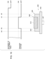
- Fig. 10 is a sequence diagram illustrating an example of a relationship between a timing of control by the controller 600 and a timing at which the medium 500 held by the jig 430 is transported to the transfer position.
- Fig. 10 illustrates an example of timings during a period for which an attachment table 420 moves from the preparation position to the transfer position and an image is transferred onto a medium 500.
- the controller 600 turns on a driving signal of a driving signal that moves the attachment table 420 as illustrated in Fig. 10 after adjusting a height of the attachment table 420 to a transfer execution height at the preparation position. This causes the attachment table 420 to move from the preparation position toward the transfer position along a transport rail 410 (see Fig. 1 ).
- the controller 600 turns on an output signal for applying a transfer voltage to the backup roll 140 (see Fig. 2 ) at a timing (a timing indicated by (b) in Fig. 10 ) at which a front end (a front end of a front surface 531) of the medium 500 held by the jig 430 attached to the attachment table 420 reaches the transfer position.
- a voltage of a predetermined magnitude is applied to the backup roll 140 by a power source 160, and a transfer electric field is formed between the backup roll 140 and the medium 500.
- the controller 600 turns off the output signal for applying the voltage to the backup roll 140 at a timing (a timing indicated by (c) in Fig. 10 ) at which the medium 500 held by the jig 430 attached to the attachment table 420 passes the transfer position and a rear end (a rear end of the front surface 510) of the medium 500 reaches the transfer position.
- a timing indicated by (c) in Fig. 10 at which the medium 500 held by the jig 430 attached to the attachment table 420 passes the transfer position and a rear end (a rear end of the front surface 510) of the medium 500 reaches the transfer position.
- the controller 600 turns off the driving signal of the driving device that moves the attachment table 420.
- a voltage is applied to the backup roll 140 during a period between (b) and (c) in Fig. 10 , in other words, during a period for which the medium 500 is passing the transfer position and the front surface 510 of the medium 500 and the intermediate transfer belt 131 are in contact with each other.
- This makes it possible to transfer an image formed with particles on the intermediate transfer belt 131 onto the front surface 510 of the medium 500 by a transfer electric field formed between the backup roll 140 and the front surface 510 of the medium 500.
- no voltage is applied to the backup roll 140 during a period between (a) and (b) in Fig. 10 , in other words, during a period from a timing at which the front end (the front end of the upper surface 431) of the jig 430 attached to the attachment table 420 reaches the transfer position to a timing at which the front end (the front end of the front surface 510) of the medium 500 reaches the transfer position.
- no voltage is applied to the backup roll 140 during a period between (c) and (d) in Fig.
- no voltage is applied to the backup roll 140 during a period for which the intermediate transfer belt 131 and the upper surface 431 of the jig 430 are in contact with each other.
- the image forming apparatus 10 forms a transfer electric field between the backup roll 140 and the image formation surface of the medium 500 by connecting the image formation surface of the medium 500 to ground with the jig 430 interposed therebetween and applying a predetermined voltage to the backup roll 140 by the power source 160 in the above exemplary embodiments, this is not restrictive.
- the image forming apparatus 10 may form a transfer electric field between the backup roll 140 and the image formation surface of the medium 500 by connecting the backup roll 140 to ground and applying a voltage to the jig 430 and the table part 422.
- the controller 600 need just control a timing at which a voltage is applied to the jig 430 or the table part 422 instead of a timing at which a voltage is applied to the backup roll 140.
- the configuration of the jig 430 attached to the attachment table 420 be simple since the attachment table 420 of the transport mechanism 400 moves along the transport rail 410.
- the configuration in which the image formation surface of the medium 500 is connected to ground with the jig 430 interposed therebetween and a predetermined voltage is applied to the backup roll 140 by the power source 160 is employed as in the above exemplary embodiments, it is unnecessary to connect a member such as a power source to the jig 430. This may simplify the configuration of the jig 430 and the configuration of the attachment table 420 to which the jig 430 is attached.
- particles are less likely to be attached to the support unit than in a case where the support unit that supports the recording medium and the transfer unit are directly conductive with each other.
- particles are less likely to be attached to the support unit than in a case where the support unit makes contact with the transfer unit.
- particles are less likely to be attached to the support unit than in a case where the height of the support unit is equal to or higher than the height of the image formation surface of the recording medium.
- particles are less likely to be attached to the support unit than in a case where the support unit does not have a non-conductive portion on the portion that makes contact with the transfer unit.
- an electric field can be formed between the transfer unit and the image formation surface of the recording medium by using the support unit.
- particles are less likely to be attached to the support unit than in a case where a voltage is applied during a period for which the transfer unit and the image formation surface of the recording medium are not in contact with each other.
- particles are less likely to be attached to a front side of the support unit than in a case where a voltage is applied before the transfer unit and the image formation surface of the recording medium make contact with each other.
- particles attached to the support unit that has passed through the transfer unit can be reduced as compared with a case where the cleaning unit is not provided.
Landscapes
- Physics & Mathematics (AREA)
- General Physics & Mathematics (AREA)
- Engineering & Computer Science (AREA)
- Computer Vision & Pattern Recognition (AREA)
- Multimedia (AREA)
- Signal Processing (AREA)
- Electrostatic Charge, Transfer And Separation In Electrography (AREA)
Abstract
Description
- The present disclosure relates to an image forming apparatus.
-
Japanese Patent No. 3292954 - Some image forming apparatuses bring a transfer unit into contact with an image formation surface of a recording medium transported by a transport unit and thereby transfer an image formed with particles such as toner onto the recording medium. The transfer unit transfers the image formed with particles onto the recording medium by an electric field formed between the transfer unit and the recording medium.
- In such an image forming apparatus, it is desirable to provide a support unit that supports a recording medium from a perspective of making misregistration of the recording medium less likely to occur due to a shock caused when the transfer unit makes contact with the recording medium. Meanwhile, in a case where the recording medium is supported by the support unit, if the support unit and the transfer unit are directly conductive with each other, particles such as toner may be undesirably attached from the transfer unit to the support unit by an electric field between the transfer unit and the support unit.
- Accordingly, it is an object of the present disclosure to provide a technique of making particles less likely to be attached to a support unit that supports a recording medium than in a case where the support unit and a transfer unit are directly conductive with each other.
- According to a first aspect of the present disclosure, there is provided an image forming apparatus including: a transport unit that transports a recording medium; a transfer unit that transfers an image formed with particles onto an image formation surface of the recording medium transported by the transport unit by an electric field formed between the transfer unit and the image formation surface by making contact with the image formation surface; and a support unit that supports the recording medium, is transported to the transfer unit together with the recording medium by the transport unit, and is not directly conductive with the transfer unit.
- According to a second aspect of the present disclosure, the image forming apparatus according to the first aspect is configured such that the support unit does not make contact with the transfer unit.
- According to a third aspect of the present disclosure, the image forming apparatus according to the first or second aspect is configured such that the support unit supports a side surface of the recording medium and has a height lower than a height of the image formation surface of the recording medium.
- According to a fourth aspect of the present disclosure, the image forming apparatus according to the first aspect is configured such that the support unit makes contact with the transfer unit and has, on a portion that makes contact with the transfer unit, a non-conductive layer having lower electric conductivity than the image formation surface of the recording medium.
- According to a fifth aspect of the present disclosure, the image forming apparatus according to the fourth aspect is configured such that a portion of the support unit that makes contact with the recording medium has electric conductivity, and the support unit is conductive with the image formation surface of the recording medium by making contact with the recording medium.
- According to a sixth aspect of the present disclosure, the image forming apparatus according to any one of the first to fifth aspects is configured to further include a power source that applies a voltage for forming the electric field, wherein the power source applies no voltage during a period for which the transfer unit and the image formation surface of the recording medium are not in contact with each other.
- According to a seventh aspect of the present disclosure, the image forming apparatus according to the sixth aspect is configured such that the support unit makes contact with the transfer unit before the transfer unit and the image formation surface of the recording medium make contact with each other; and the power source applies no voltage before the transfer unit and the image formation surface of the recording medium make contact with each other.
- According to an eighth aspect of the present disclosure, the image forming apparatus according to any one of the first to seventh aspects is configured to further include a cleaning unit that cleans the support unit by making contact with the support unit that has passed through the transfer unit.
- According to the first aspect of the present disclosure, particles are less likely to be attached to the support unit than in a case where the support unit that supports the recording medium and the transfer unit are directly conductive with each other.
- According to the second aspect of the present disclosure, particles are less likely to be attached to the support unit than in a case where the support unit makes contact with the transfer unit.
- According to the third aspect of the present disclosure, particles are less likely to be attached to the support unit than in a case where the height of the support unit is equal to or higher than the height of the image formation surface of the recording medium.
- According to the fourth aspect of the present disclosure, particles are less likely to be attached to the support unit than in a case where the support unit does not have a non-conductive portion on the portion that makes contact with the transfer unit.
- According to the fifth aspect of the present disclosure, an electric field can be formed between the transfer unit and the image formation surface of the recording medium by using the support unit.
- According to the sixth aspect of the present disclosure, particles are less likely to be attached to the support unit than in a case where a voltage is applied during a period for which the transfer unit and the image formation surface of the recording medium are not in contact with each other.
- According to the seventh aspect of the present disclosure, particles are less likely to be attached to a front side of the support unit than in a case where a voltage is applied before the transfer unit and the image formation surface of the recording medium make contact with each other.
- According to the eighth aspect of the present disclosure, particles attached to the support unit that has passed through the transfer unit can be reduced as compared with a case where the cleaning unit is not provided.
- Exemplary embodiments of the present disclosure will be described in detail based on the following figures, wherein:
-
Fig. 1 illustrates a configuration of an image forming apparatus to which the present exemplary embodiment is applied; -
Fig. 2 illustrates a configuration of a transfer unit; -
Figs. 3A to 3C illustrate operation of a transport mechanism before start of image formation by the transfer unit, andFig. 3A illustrates how the height is controlled,Fig. 3B illustrates a state where an attachment table has retreated to a preparation position after the height control, andFig. 3C illustrates a state where the transfer unit starts transfer of an image; -
Figs. 4A and 4B illustrate a configuration and operation of a fixing unit, andFig. 4A illustrates a state where openings of the fixing unit are closed, andFig. 4B illustrates a state where the openings of the fixing unit are opened; -
Fig. 5 is a perspective view illustrating a jig and a medium held by the jig to which the first exemplary embodiment is applied; -
Figs. 6A and 6B illustrate a relationship between (i) the jig and the medium to which the first exemplary embodiment is applied and (ii) an intermediate transfer belt and a backup roll, andFig. 6A illustrates an example using the jig illustrated inFig. 5 , andFig. 6B illustrates an example using a modification of the jig; -
Figs. 7A and 7B illustrate a jig and a medium to which the second exemplary embodiment is applied, andFig. 7A is a view of the jig and the medium viewed from an upper side, andFig. 7B is a cross-sectional view of the jig and the medium taken along a transport direction in a central part in a width direction thereof; -
Figs. 8A and 8B illustrate a jig and a medium to which a modification of the second exemplary embodiment is applied, andFig. 8A is a view of the jig and the medium viewed from an upper side, andFig. 8B is a cross-sectional view of the jig and the medium taken along the transport direction at a central part in a width direction thereof; -
Figs. 9A and 9B illustrate a jig and a medium to which a modification of the second exemplary embodiment is applied, andFig. 9A is a view of the jig and the medium viewed from an upper side, andFig. 9B is a cross-sectional view of the jig and the medium taken along the transport direction at a central part in a width direction thereof; and -
Fig. 10 is a sequence diagram illustrating an example of a relationship between a timing of control by a controller and a timing at which the medium held by the jig is transported to a transfer position. - An exemplary embodiment of the present disclosure is described in detail below with reference to the attached drawings. An image forming apparatus according to the present exemplary embodiment is an image forming apparatus employing digital printing. Although an electrophotographic system, an inkjet system, and the like are known as digital printing systems, the electrophotographic system is assumed in the present exemplary embodiment. In the electrophotographic system, a transfer unit and a medium are brought into contact with each other when an image is transferred onto the medium. Furthermore, in the present exemplary embodiment, any of media having various thicknesses and shapes such as metal, glass, and tile is assumed as an object on which an image is to be printed.
-
Fig. 1 illustrates a configuration of an image forming apparatus to which the present exemplary embodiment is applied. Theimage forming apparatus 10 includes atransfer unit 100, a fixingunit 200, a medium attachingdetaching unit 300, and atransport mechanism 400. Furthermore, theimage forming apparatus 10 includes acontroller 600 having one or more processors, which are computing units, a memory serving as a working region in data processing, and a storage device that holds a program and data. Although thecontroller 600 is a single controller that controls operation of the wholeimage forming apparatus 10 in this example, thecontroller 600 may be individually provided in units such as thetransfer unit 100, the fixingunit 200, and thetransport mechanism 400. - The
transfer unit 100 is a unit that transfers an image formed with particles such as toner onto a recording medium 500 (hereinafter simply referred to as a medium 500). The fixingunit 200 is a unit that fixes, on a surface of the medium 500, an image transferred by thetransfer unit 100 by heating the medium 500. The medium attachingdetaching unit 300 is a unit in which a user of theimage forming apparatus 10 attaches the medium 500 to an attachment table (described later) provided in thetransport mechanism 400. Thetransport mechanism 400 is provided across thetransfer unit 100, the fixingunit 200, and the medium attachingdetaching unit 300, and transports the medium 500 on which an image is to be printed to theunits Fig. 1 . -
Fig. 2 illustrates a configuration of thetransfer unit 100. Thetransfer unit 100 forms an image with charged particles and transfers the image onto the medium 500 by generating an electric field. Thetransfer unit 100 includes a developingdevice 110, afirst transfer roll 120, and anintermediate transfer belt 131. Theintermediate transfer belt 131 is tensioned between the developingdevice 110 and a position where an image is transferred onto the medium 500 byrollers backup roll 140. Furthermore, thetransfer unit 100 includes acleaning device 150 for removing particles attached to theintermediate transfer belt 131. Furthermore, thetransfer unit 100 includes apower source 160 that applies a predetermined voltage to thebackup roll 140. - The developing
device 110 is a unit that forms, on a photoreceptor, an electrostatic latent image of an image to be transferred and develops the image by attaching charged particles to the electrostatic latent image on the photoreceptor. As the developingdevice 110, an existing device used in an electrophotographic image forming apparatus can be used.Fig. 2 illustrates an example of a configuration employed in a case where color image formation processing is performed by using four colors, that is, three colors: yellow, magenta, and cyan, and an additional one color: black. The developingdevice 110 is provided for each of these colors, and the developingdevices 110 for yellow, magenta, cyan, and black are given alphabets (color signs) Y, M, C, and K indicative of the colors inFig. 2 . In the following description, the suffixes are omitted in a case where the colors of the developingdevices 110 need not be distinguished although the suffixes Y, M, C, and K are given to the reference signs in a case where the colors are distinguished. - The
first transfer roll 120 is a unit used to transfer (first transfer) an image formed by the developingdevice 110 onto theintermediate transfer belt 131. Thefirst transfer roll 120 is disposed so as to face the photoreceptor of the developingdevice 110, and theintermediate transfer belt 131 is located between the developingdevice 110 and thefirst transfer roll 120. Thefirst transfer roll 120 is provided corresponding to each of the developingdevices Fig. 2 , the first transfer rolls 120 corresponding to the developingdevices - The
intermediate transfer belt 131, therollers backup roll 140 are units used to transfer an image formed by the developingdevice 110 onto the medium 500. As illustrated inFig. 2 , theintermediate transfer belt 131 rotates in a direction indicated by the arrows inFig. 2 (a counterclockwise direction in the example illustrated inFig. 2 ) while being suspended around therollers backup roll 140 in a tensioned state. For example, one or both of therollers intermediate transfer belt 131 is pulled by rotation of this(these) roller(s). In this way, theintermediate transfer belt 131 rotates. - An outer surface of the
intermediate transfer belt 131 in the example of the configuration inFig. 2 is a surface (hereinafter referred to as a "transfer surface") on which an image is held. An image is transferred from the photoreceptor of the developingdevice 110 onto the transfer surface of theintermediate transfer belt 131 when theintermediate transfer belt 131 passes between the developingdevice 110 and thefirst transfer roll 120. In the example of the configuration illustrated inFig. 2 , images of the respective colors: yellow (Y), magenta (M), cyan (C), and black (K) are superimposed on the transfer surface by the developingdevices - The
backup roll 140 transfers (second transfer) the image onto the medium 500 by bringing the transfer surface of theintermediate transfer belt 131 into contact with the medium 500. A predetermined voltage is applied to thebackup roll 140 by thepower source 160 when the image is transferred. This generates an electric field (hereinafter referred to as a "transfer electric field") in a range including thebackup roll 140 and the medium 500, thereby transferring the image formed with charged particles from theintermediate transfer belt 131 onto the medium 500. As described above, to transfer an image from theintermediate transfer belt 131 onto the medium 500, an electric current need to flow from thebackup roll 140 to the medium 500 through theintermediate transfer belt 131. In a case where the medium 500 is a conductor such as a metal, an electric current flows through the medium 500 itself, and therefore an image is transferred onto a surface of the medium 500 by generating a transfer electric field. On the other hand, in a case where the medium 500 is not a conductor, no electric current flows through the medium 500, and therefore an image cannot be transferred in this state. In view of this, in a case where the medium 500 is not a conductor, an electric current is passed through the medium 500 by taking a measure such as forming a layer made of an electrically conductive material (hereinafter referred to as an "electrically conductive layer") in advance in at least a region on the surface of the medium 500 where an image is to be formed. - A procedure of transfer of an image by the
intermediate transfer belt 131 is described. When theintermediate transfer belt 131 rotates, images of the respective colors: yellow (Y), magenta (M), cyan (C), and black (K) are sequentially superimposed on the transfer surface (outer surface inFig. 2 ) of theintermediate transfer belt 131 by the developingdevices intermediate transfer belt 131 further rotates, the image formed on the transfer surface of theintermediate transfer belt 131 reaches a position (hereinafter referred to as a "transfer position") where theintermediate transfer belt 131 makes contact with the medium 500. As described above, a voltage is applied to thebackup roll 140. This generates a transfer electric field, thereby transferring the image from theintermediate transfer belt 131 onto the medium 500. - The
cleaning device 150 is a unit that removes particles attached to the transfer surface of theintermediate transfer belt 131. Thecleaning device 150 is provided at a position on a downstream side relative to the transfer position and an upstream side relative to the developingdevice 110Y and thefirst transfer roll 120Y in a direction in which theintermediate transfer belt 131 rotates. With this configuration, particles remaining on the transfer surface of theintermediate transfer belt 131 are removed by thecleaning device 150 after the image is transferred from theintermediate transfer belt 131 onto the medium 500. In a next operation cycle, an image is newly transferred (first transfer) onto the transfer surface from which particles have been removed. Configuration ofTransport Mechanism 400 and Attachment Structure for Attachment ofMedium 500 - An attachment structure for attachment of the medium 500 is described. In the present exemplary embodiment, it is assumed that the medium 500 can have various thicknesses and shapes. In a case where the medium 500 directly placed on a transport path constituted by a belt and a roller is transported, it is difficult to bring the
intermediate transfer belt 131 into contact with the medium 500 in a predetermined relationship since a height of the medium 500 relative to the transport path varies at the transfer position of thetransfer unit 100 in a case where a thickness and a shape of the medium 500 vary. Specifically, such a situation can occur in which the medium 500 does not make contact with theintermediate transfer belt 131 in a case where the height of the medium 500 is low, and a strong shock is caused when the medium 500 makes contact with theintermediate transfer belt 131 in a case where the height of the medium 500 is high. In view of this, thetransport mechanism 400 according to the present exemplary embodiment has the attachment table 420 having a height adjuster and transports the medium 500 placed on the attachment table 420 together with the attachment table 420. - The
transport mechanism 400 includes thetransport rail 410 that specifies a transport path for the medium 500 and the attachment table 420 that moves on the transport rail 410 (seeFig. 2 ). The attachment table 420 includes aleg part 421 attached to thetransport rail 410 and atable part 422 on which the medium 500 is to be placed. Furthermore, ajig 430 that holds the medium 500 on thetable part 422 is attached to thetable part 422. - In the example of the configuration illustrated in
Fig. 1 , thetransport rail 410 is disposed so as to extend from the medium attachingdetaching unit 300 to thetransfer unit 100 while passing the fixingunit 200. An end portion of thetransport rail 410 on a medium attachingdetaching unit 300 side is the transport start position and the transport end position. The attachment table 420 is transported leftward inFig. 1 from the transport start position of the medium attachingdetaching unit 300, and an image is transferred onto the medium 500 in thetransfer unit 100. Then, the attachment table 420 is transported rightward inFig. 1 , and reaches the transport end position of the medium attachingdetaching unit 300 after the image is fixed on the medium 500 in the fixingunit 200. - The
leg part 421 is attached to thetransport rail 410 and moves on thetransport rail 410. A mechanism for moving theleg part 421 on thetransport rail 410 is not limited in particular. For example, theleg part 421 may be provided with a driving device so as to be movable on its own or thetransport rail 410 may be provided with a unit that pulls theleg part 421. Furthermore, theleg part 421 has a height controller that controls a height of thetable part 422. A configuration of the height controller is not limited in particular. For example, thetable part 422 may be moved up and down by rack and pinion and a drive motor. Alternatively, the height of thetable part 422 may be controlled by manually operating a gear that is linked with the height of thetable part 422. Furthermore, various methods can be used as an operation method for controlling the height. For example, an input interface for input to a controller of the drive motor may be prepared, and an operator of theimage forming apparatus 10 may manually input and set height data by using the input interface. Alternatively, the height of the medium 500 attached to the attachment table 420 may be automatically detected by using a sensor, and the drive motor may be controlled so that the medium 500 is located at an appropriate height. - The
table part 422 is a table that is attached to theleg part 421 and on which the medium 500 is placed with thejig 430 interposed therebetween. Thetable part 422 is provided with a fastener (not illustrated) for positioning thejig 430. Anyjigs 430 compatible with this fastener can be positioned and attached to thetable part 422 irrespective of shapes thereof. - Furthermore, the
table part 422 is attached so as to float up and sink down with respect to theleg part 421 in accordance with a pressure applied from an upper side. The configuration in which thetable part 422 floats up and sinks down is, for example, realized by interposing an elastic body at a portion where thetable part 422 and theleg part 421 are joined. By employing such a configuration, a shock caused when the medium 500 held by thejig 430 attached to thetable part 422 makes contact with theintermediate transfer belt 131 of thetransfer unit 100 is lessened. - The
table part 422 according to the present exemplary embodiment is made of an electrically conductive material. Furthermore, thetable part 422 is in contact with a grounding member (not illustrated) and is connected to ground with the grounding member interposed therebetween. - The
jig 430 is an example of a support unit and is a device that holds the medium 500 and is attached to thetable part 422. A portion of thejig 430 attached to thetable part 422 has a shape and a structure compatible with the fastener of thetable part 422. Furthermore, thejig 430 has a shape for holding the medium 500. Therefore,media 500 having various shapes and sizes can be placed on the attachment table 420 by preparingjigs 430 compatible with the shapes and sizes of themedia 500. - The
jig 430 according to the present exemplary embodiment is made of an electrically conductive material. Furthermore, the portion of thejig 430 attached to thetable part 422 is conductive with thetable part 422. Furthermore, thejig 430 supports the medium 500 so as to be conductive with a surface (an image formation surface, which will be described later) of the medium 500 including a region where an image is to be formed. In this way, the image formation surface of the medium 500 supported by thejig 430 is connected to ground with thejig 430 and thetable part 422 interposed therebetween. - Note that a relationship between the
jig 430 and the medium 500 will be described in detail later. - The
image forming apparatus 10 according to the present exemplary embodiment has thetransport mechanism 400 configured as above and therefore can print an image on any of themedia 500 having various shapes and sizes. However, before start of image transfer operation, the height of thetable part 422 is controlled in order to prevent a strong shock from being caused by contact of the medium 500 with theintermediate transfer belt 131 of thetransfer unit 100 or prevent failure to bring the medium 500 into contact with theintermediate transfer belt 131 when an image is transferred onto the medium 500. -
Figs. 3A to 3C illustrate operation of thetransport mechanism 400 before start of image formation by thetransfer unit 100.Fig. 3A illustrates how the height is controlled,Fig. 3B illustrates a state where the attachment table 420 has retreated to a preparation position after the height control, andFig. 3C illustrates a state where thetransfer unit 100 starts transfer of an image. - In a case where an image is formed on the medium 500, first, the medium 500 held by the
jig 430 is placed on the attachment table 420 at the transport start position of the medium attachingdetaching unit 300. Then, the medium 500 is lowered to a height at which the medium 500 does not make contact with theintermediate transfer belt 131 of thetransfer unit 100 by the height controller of the attachment table 420, and then the attachment table 420 on which the medium 500 is placed is moved to a position below the transfer position of thetransfer unit 100. - Next, the height of the attachment table 420 is controlled so that the medium 500 makes contact with the
intermediate transfer belt 131 with a strength appropriate for transfer of the image at the transfer position (arrow a inFig. 3A ). When the height is controlled, information on an appropriate height (hereinafter referred to as a "transfer execution height") thus obtained is held, for example, in the memory of the controller 600 (seeFig. 1 ). Then, the attachment table 420 is lowered to a height where the medium 500 does not make contact with theintermediate transfer belt 131 and moves to the preparation position for transfer operation (arrow b inFig. 3A ). - When the attachment table 420 moves to the preparation position, the height of the attachment table 420 is adjusted to the transfer execution height on the basis of the information obtained in the height control. Then, the attachment table 420 moves to the transfer position (arrow c in
Fig. 3B ), and transfer of the image starts when the medium 500 makes contact with theintermediate transfer belt 131 at the transfer position (Fig. 3C ). - After the image is transferred onto the medium 500 in the
transfer unit 100, the image is fixed in the fixingunit 200. In the present exemplary embodiment, an image is formed on any of themedia 500 having various thicknesses and shapes, and therefore the fixing processing is performed by a non-contact-type device. The fixingunit 200 melts particles forming the image transferred onto the medium 500 by heating the particles and thereby fixes the particles on the surface of the medium 500. -
Figs. 4A and 4B illustrate a configuration and operation of the fixingunit 200.Fig. 4A illustrates a state where openings of the fixingunit 200 are closed, andFig. 4B illustrates a state where the openings of the fixingunit 200 are opened. The fixingunit 200 includes a carry-inopening 201, which is an opening through which the medium 500 is carried into the fixingunit 200, and a carry-outopening 202, which is an opening through which the medium 500 is carried out of the fixingunit 200. Furthermore, the carry-inopening 201 and the carry-outopening 202 of the fixingunit 200 according to the present exemplary embodiment are provided with an opening and closing member and are configured to be opened when the medium 500 is carried into or out of the fixingunit 200 and be closed when the fixing processing is performed. - The fixing
unit 200 includes aheat source 210 for thermal fixation. Theheat source 210 can be, for example, any of various existing heat sources such as a halogen lamp, a ceramic heater, and an infrared lamp. Instead of theheat source 210, a device that heats particles forming the image by emitting infrared laser may be used. The fixingunit 200 according to the present exemplary embodiment is provided with a member that can cover theheat source 210, and is configured so that theheat source 210 is exposed when the fixing processing is performed. - In the example illustrated in
Figs. 4A and 4B , roll-upshutters opening 201 and the carry-outopening 202. Theshutters Fig. 4A ) except when the medium 500 is carried into and out of the fixingunit 200 and thereby prevent a decrease in internal temperature. Theshutter 220 of the carry-inopening 201 opens when the medium 500 is carried into the fixingunit 200, and theshutter 230 of the carry-outopening 202 opens when the medium 500 is carried out of the fixing unit 200 (seeFig. 4B ). - In the example illustrated in
Figs. 4A and 4B , a roll-upshutter 240 is provided as the covering member that covers theheat source 210. Theshutter 240 closes in a case where theshutter 220 of the carry-inopening 201 and/or theshutter 230 of the carry-outopening 202 open(s) (seeFig. 4B ). This may keep a decrease in temperature of theheat source 210 small even in a case where the carry-inopening 201 and/or the carry-outopening 202 open(s) and the internal temperature decreases. - In the example illustrated in
Fig. 4B , a state where both of theshutter 220 of the carry-inopening 201 and theshutter 230 of the carry-outopening 202 are opened is illustrated for convenience of description. In actual operation, theshutter 230 of the carry-outopening 202 remains closed when the medium 500 is carried into the fixingunit 200, and theshutter 220 of the carry-inopening 201 remains closed when the medium 500 is carried out of the fixingunit 200. This keeps a decrease in internal temperature small. - The
shutters Figs. 4A and 4B are an example of the opening and closing members of the carry-inopening 201 and the carry-outopening 202 and the covering member of theheat source 210. The opening and closing members and covering member are not limited to the above configuration, as long as the opening and closing members and covering member keep a decrease in internal temperature of the fixingunit 200 and temperature of theheat source 210 small. For example, an opening and closing door may be provided instead of theshutters Figs. 4A and 4B . As the opening and closing member of the carry-outopening 202 through which the medium 500 passes after the fixing processing is finished, a curtain made of a heat insulating material or air curtain may be used to prevent leakage of internal air. - See
Fig. 1 again. As described above, the medium attachingdetaching unit 300 is a unit that is located at the transport start position and the transport end position, which are an end portion of thetransport rail 410. In the medium attachingdetaching unit 300, thejig 430 is attached and detached to and from the attachment table 420 or the medium 500 is attached and detached to and from thejig 430 attached to the attachment table 420. - Furthermore, the medium attaching
detaching unit 300 according to the present exemplary embodiment includes acleaning device 350 for removing particles attached to an upper surface 431 (seeFig. 5 , which will be described later) of thejig 430. Thecleaning device 350 has, for example, a brush, a web, or the like that makes contact with theupper surface 431 of thejig 430. - After an image is fixed on the medium 500 in the fixing
unit 200, the attachment table 420 on which thejig 430 holding the medium 500 is placed moves to the transport end position of the medium attachingdetaching unit 300. At the transport end position of the medium attachingdetaching unit 300, the medium 500 is removed from thejig 430 attached to the attachment table 420. Then, the particles attached to theupper surface 431 of thejig 430 are removed by thecleaning device 350. - Then, a
new medium 500 is placed on thejig 430, and image formation operation on thisnew medium 500 is performed. - As described above, in the
image forming apparatus 10 according to the present exemplary embodiment, an image formed with particles is transferred from the transfer surface of theintermediate transfer belt 131 onto the medium 500 by bringing the transfer surface of theintermediate transfer belt 131 into contact with the medium 500 held by thejig 430. During this process, the transfer surface of theintermediate transfer belt 131 and theupper surface 431 of thejig 430 sometimes make contact with each other, and particles are sometimes attached from theintermediate transfer belt 131 to theupper surface 431 of thejig 430. In a case where particles are attached to theupper surface 431 of thejig 430, the particles are sometimes attached to anew medium 500 and smear thenew medium 500 when thenew medium 500 is placed on thejig 430 after image formation operation on the medium 500 is finished. - In the present exemplary embodiment, the particles attached to the
jig 430 are removed by thecleaning device 350, and therefore it is less likely that the particles are attached to and smear the medium 500 placed on thejig 430. - As described above, in the
transfer unit 100 according to the present exemplary embodiment, when the attachment table 420 on which the medium 500 is placed moves to the transfer position, thebackup roll 140 and the image formation surface of the medium 500 make contact with each other with theintermediate transfer belt 131 interposed therebetween. This forms a transfer electric field between thebackup roll 140 and the image formation surface of the medium 500, thereby transferring an image formed with particles from the transfer surface of theintermediate transfer belt 131 onto the image formation surface of the medium 500. - As described above, the
jig 430 holding the medium 500 has electric conductivity and is connected to ground with thetable part 422 interposed therebetween. Accordingly, if theintermediate transfer belt 131 makes contact with thejig 430 and thebackup roll 140 and thejig 430 become directly conductive with each other with theintermediate transfer belt 131 interposed therebetween when the attachment table 420 moves to the transfer position, particles are sometimes attached from the transfer surface of theintermediate transfer belt 131, for example, onto theupper surface 431 of thejig 430 due to an electric field between thebackup roll 140 and thejig 430. - In the description of the present exemplary embodiment, a state where the
jig 430 and members that constitute thetransfer unit 100 such as theintermediate transfer belt 131 and thebackup roll 140 are directly conductive with each other means a state where thejig 430 is conductive with members that constitute thetransfer unit 100 by directly making contact with or facing the members without the medium 500 interposed therebetween. Specifically, in a case where thebackup roll 140 and the image formation surface of the medium 500 make contact with each other with theintermediate transfer belt 131 interposed therebetween, thejig 430 is not directly conductive with theintermediate transfer belt 131 and thebackup roll 140 although thejig 430 is conductive with theintermediate transfer belt 131 and thebackup roll 140 with the medium 500 interposed therebetween. - In the present exemplary embodiment, the
jig 430 supports the medium 500 so as not to make contact with theintermediate transfer belt 131, and thereby thejig 430 is prevented from becoming directly conductive with theintermediate transfer belt 131 and thebackup roll 140. In this way, particles are less likely to be attached from theintermediate transfer belt 131 onto thejig 430. - A shape of the
jig 430 and a relationship between thejig 430 and theintermediate transfer belt 131 and thebackup roll 140 according to the present exemplary embodiment are described in detail below. In the following description, the transport direction means a transport direction (a direction indicated by arrow c inFig. 3B ) in which the attachment table 420, the medium 500 attached to the attachment table 420, or the like is transported from the preparation position to the transport end position by passing through the transfer position. -
Fig. 5 is a perspective view illustrating thejig 430 and the medium 500 held by thejig 430 to which the first exemplary embodiment is applied. -
Figs. 6A and 6B illustrate a relationship between (i) thejig 430 and the medium 500 to which the first exemplary embodiment is applied and (ii) theintermediate transfer belt 131 and thebackup roll 140, andFig. 6A illustrates an example using thejig 430 illustrated inFig. 5 , andFig. 6B illustrates an example using a modification of thejig 430. Note thatFigs. 6A and 6B are cross-sectional views of thejig 430 and the medium 500 taken along the transport direction at a central part in a width direction thereof. - The medium 500 according to the present exemplary embodiment has a
front surface 510 and arear surface 520 that are rectangular, a pair of first side surfaces 530 that connect thefront surface 510 and therear surface 520 and face each other, and a pair of second side surfaces 540 that connect thefront surface 510 and therear surface 520 and face each other, and has a flattened rectangular parallelepiped shape as a whole. In this example, thefront surface 510 of the medium 500 is the image formation surface including the region where an image is to be formed. The whole medium 500 including thefront surface 510, which is the image formation surface, according to the present exemplary embodiment is made of a conductor. - As described above, the
jig 430 holds the medium 500 and is attached to thetable part 422. - The
jig 430 according to the present exemplary embodiment has the rectangularupper surface 431 that faces theintermediate transfer belt 131 when transported to the transfer position and a rectangularlower surface 432 opposite to theupper surface 431, and has a rectangular parallelepiped shape as a whole. Thejig 430 is attached to thetable part 422 so that thelower surface 432 faces thetable part 422, and thejig 430 is conductive with thetable part 422 through thelower surface 432. - Furthermore, the
jig 430 has, in a central part thereof in the transport direction of thetransport mechanism 400, a recessedpart 435 that is recessed from theupper surface 431 toward thelower surface 432. The medium 500 is inserted into a space formed inside the recessedpart 435 of thejig 430, and thus the medium 500 is supported in the recessedpart 435. In this example, the medium 500 is inserted into the recessedpart 435 of thejig 430 so that the pair of first side surfaces 530 extend along the transport direction in which the medium 500 is transported by thetransport mechanism 400 and the pair of second side surfaces 540 extend along a width direction of the medium 500 orthogonal to the transport direction. - The recessed
part 435 of thejig 430 has an inner peripheral surface that matches the shape of the medium 500. Specifically, the recessedpart 435 has a pair of first innerperipheral surfaces 436 that extend along the transport direction of thetransport mechanism 400 and face each other with the space in the recessedpart 435 interposed therebetween and a pair of second innerperipheral surfaces 437 that extend along the width direction orthogonal to the transport direction of thetransport mechanism 400 and face each other with the space in the recessedpart 435 interposed therebetween. Furthermore, the recessedpart 435 has abottom surface 438 extending from lower ends of the first innerperipheral surfaces 436 and the second innerperipheral surfaces 437 along the transport direction and the width direction. - In the recessed
part 435, a length of each of the first innerperipheral surfaces 436 along the transport direction, in other words, an interval between the second innerperipheral surfaces 437 that face each other is equal to a length of the medium 500 in the transport direction. Furthermore, in the recessedpart 435, a length of each of the second innerperipheral surfaces 437 along the width direction, in other words, an interval between the first innerperipheral surfaces 436 that face each other is equal to a length of the medium 500 along the width direction. - Furthermore, a height of the first inner
peripheral surfaces 436 and the second innerperipheral surfaces 437 of the recessedpart 435 of thejig 430 according to the present exemplary embodiment, in other words, a height of the recessedpart 435 from thebottom surface 438 to theupper surface 431 is lower than a height of the medium 500, more specifically, a height of the first side surfaces 530 and the second side surfaces 540 of the medium 500. - The medium 500 is inserted into the recessed
part 435, and thereby thejig 430 supports the first side surfaces 530 and the second side surfaces 540, which are side surfaces of the medium 500. Specifically, when the medium 500 is inserted into the recessedpart 435 of thejig 430, the first innerperipheral surfaces 436 and the second innerperipheral surfaces 437 of the recessedpart 435 of thejig 430 and the first side surfaces 530 and the second side surfaces 540 of the medium 500 make contact with each other. Furthermore, thebottom surface 438 of the recessedpart 435 of thejig 430 and therear surface 520 of the medium 500 make contact with each other. - In the present exemplary embodiment, when the medium 500 is inserted into the recessed
part 435, thejig 430 and the medium 500 make contact with each other, and thereby thejig 430 and the medium 500 become conductive with each other. As a result, thefront surface 510 of the medium 500, which is the image formation surface, is connected to ground with thejig 430 and thetable part 422 interposed therebetween. - Furthermore, in the present exemplary embodiment, the height of the recessed
part 435 of thejig 430 is lower than the height of the medium 500, as described above. Accordingly, in a state where the medium 500 is in the recessedpart 435 of thejig 430 attached to thetable part 422, the height of thejig 430 is lower than a height of the image formation surface of the medium 500. More specifically, a height from thetable part 422 to theupper surface 431 of thejig 430 is lower than a height from thetable part 422 to thefront surface 510 of the medium 500, which is the image formation surface. Furthermore, in a case where the attachment table 420 moves to the transfer position, a distance from the transfer surface of theintermediate transfer belt 131 to theupper surface 431 of thejig 430 is longer than a distance from the transfer surface of theintermediate transfer belt 131 to thefront surface 510 of the medium 500. - Since the
jig 430 and the medium 500 have such a relationship, theintermediate transfer belt 131 makes contact with thefront surface 510 of the medium 500 without making contact with theupper surface 431 of thejig 430 in a case where the attachment table 420 moves to the transfer position in a state where the height of the attachment table 420 has been controlled so that thefront surface 510 of the medium 500 makes contact with theintermediate transfer belt 131 with a strength appropriate for transfer of an image. Specifically, theintermediate transfer belt 131 does not make contact with a front end side of theupper surface 431 of thejig 430 in the transport direction before theintermediate transfer belt 131 makes contact with thefront surface 510 of the medium 500. - Then, an image is transferred from the transfer surface of the
intermediate transfer belt 131 onto the front surface of the medium 500 without bringing theintermediate transfer belt 131 into contact with regions of theupper surface 431 of thejig 430 on both end sides in the width direction of the medium 500 while theintermediate transfer belt 131 is in contact with thefront surface 510 of the medium 500. - Furthermore, after the image is transferred from the transfer surface of the
intermediate transfer belt 131 onto thefront surface 510 of the medium 500, the attachment table 420 is moved from the transfer position to the transport end position without bringing theintermediate transfer belt 131 into contact with a rear end side of theupper surface 431 of thejig 430 in the transport direction. - This keeps the
upper surface 431 of thejig 430 from becoming directly conductive with theintermediate transfer belt 131 and thebackup roll 140, thereby keeping particles from being attached from the transfer surface of theintermediate transfer belt 131 to theupper surface 431 of thejig 430 by a transfer electric field. - Although the
upper surface 431 of thejig 430 illustrated inFig. 6A is a flat surface extending along the transport direction of thetransport mechanism 400 and the width direction of the medium 500, theupper surface 431 need not be a flat surface. - For example, the
upper surface 431 of thejig 430 may have, on a front end side in the transport direction relative to the recessedpart 435, aninclined surface 431a whose height decreases toward the front side in the transport direction, as illustrated inFig. 6B . In a case where theupper surface 431 of thejig 430 has theinclined surface 431a on the front side in the transport direction, a distance from the transfer surface of theintermediate transfer belt 131 to theupper surface 431 of thejig 430 increases toward the front side in the transport direction. With this configuration, when the attachment table 420 enters the transfer position, the transfer surface of theintermediate transfer belt 131 and the front end of theupper surface 431 of thejig 430 are less likely to make contact with each other. This further keeps particles from being attached from the transfer surface of theintermediate transfer belt 131 to theupper surface 431 of thejig 430 by a transfer electric field. - Furthermore, the
upper surface 431 of thejig 430 may have, on a rear end side in the transport direction relative to the recessedpart 435, aninclined surface 431b whose height decreases toward the rear side in the transport direction. In a case where theupper surface 431 of thejig 430 has theinclined surface 431b on the rear side in the transport direction, a distance from the transfer surface of theintermediate transfer belt 131 to theupper surface 431 of thejig 430 increases toward the rear side in the transport direction. With this configuration, when the attachment table 420 moves from the transfer position toward the transport end position after an image is transferred from the transfer surface of theintermediate transfer belt 131 onto thefront surface 510 of the medium 500, the transfer surface of theintermediate transfer belt 131 and the rear end of theupper surface 431 of thejig 430 are less likely to make contact with each other. This further keeps particles from being attached from the transfer surface of theintermediate transfer belt 131 to theupper surface 431 of thejig 430 by a transfer electric field. - Next, the second exemplary embodiment of the present disclosure is described. Note that constituent elements similar to those in the first exemplary embodiment are given identical reference signs, and detailed description thereof is omitted.
- In the first exemplary embodiment, the
jig 430 is kept from making contact with theintermediate transfer belt 131, and thereby thejig 430 is kept from becoming directly conductive with theintermediate transfer belt 131 and thebackup roll 140. The second exemplary embodiment is different from the first exemplary embodiment in that thejig 430 is kept from becoming directly conductive with theintermediate transfer belt 131 and thebackup roll 140 by providing an insulating layer made of an insulator on a portion of thejig 430 that makes contact with theintermediate transfer belt 131. -
Figs. 7A and 7B illustrate ajig 430 and a medium 500 to which the second exemplary embodiment is applied, andFig. 7A is a view of thejig 430 and the medium 500 viewed from an upper side (intermediate transfer belt 131 side), andFig. 7B is a cross-sectional view of thejig 430 and the medium 500 taken along a transport direction in a central part in a width direction thereof.Fig. 7B illustrates anintermediate transfer belt 131 and abackup roll 140 of a transfer unit 100 (seeFig. 1 ) in addition to thejig 430 and the medium 500. - The
jig 430 according to the present exemplary embodiment has a rectangular parallelepiped shape having a rectangularupper surface 431 and a rectangularlower surface 432 and has a recessedpart 435 in a central part in the transport direction of a transport mechanism 400 (see, for example,Fig. 1 ), as in the first exemplary embodiment. Furthermore, the recessedpart 435 of thejig 430 has a pair of first innerperipheral surfaces 436 and a pair of second innerperipheral surfaces 437 that match a shape of the medium 500, and abottom surface 438. - A height of the first inner
peripheral surfaces 436 and the second innerperipheral surfaces 437 of the recessedpart 435 of thejig 430 according to the present exemplary embodiment, in other words, a height of the recessedpart 435 from thebottom surface 438 to theupper surface 431 is equal to a height of the medium 500, more specifically, a height of first side surfaces 530 and second side surfaces 540 of the medium 500, unlike the first exemplary embodiment. - Accordingly, a height of the
jig 430 is same as a height of the image formation surface of the medium 500 in a state where the medium 500 is in the recessedpart 435 of thejig 430. More specifically, a height from atable part 422 to theupper surface 431 of thejig 430 is same as a height from thetable part 422 to afront surface 510 of the medium 500, which is the image formation surface. - As in the first exemplary embodiment, a body of the
jig 430 is made of an electrically conductive material. Accordingly, thejig 430 attached to thetable part 422 is conductive with thetable part 422 through alower surface 432. Furthermore, thejig 430 is conductive with the medium 500 inserted into the recessedpart 435. Accordingly, thefront surface 510 of the medium 500, which is the image formation surface, is connected to ground with thejig 430 and thetable part 422 interposed therebetween. - Furthermore, the
jig 430 according to the present exemplary embodiment has, on theupper surface 431, anon-conductive layer 439 that keeps thejig 430 from becoming directly conductive with theintermediate transfer belt 131 and thebackup roll 140. Thenon-conductive layer 439 is a layer having lower electric conductivity than the medium 500. As the electric conductivity of thenon-conductive layer 439, lower electric conductivity is more desirable, and thenon-conductive layer 439 desirably has an insulation property. A material of thenon-conductive layer 439 is not limited in particular, and can be, for example, an insulating resin such as a phenolic resin, ceramic such as alumina, glass, or the like. - In the present exemplary embodiment, when an attachment table 420 moves to the transfer position, the
intermediate transfer belt 131 makes contact with theupper surface 431 of thejig 430 before making contact with thefront surface 510 of the medium 500. With this configuration, when the attachment table 420 moves to the transfer position, a shock caused when theintermediate transfer belt 131 makes contact with thefront surface 510 of the medium 500 is lessened due to thejig 430 as compared with a case where theintermediate transfer belt 131 makes contact with thefront surface 510 of the medium 500 without making contact with thejig 430. - Furthermore, in the present exemplary embodiment, since the
jig 430 has thenon-conductive layer 439, theintermediate transfer belt 131 makes contact with thenon-conductive layer 439 provided on theupper surface 431 of thejig 430 in a case where the attachment table 420 moves to the transfer position in a state where a height of the attachment table 420 has been controlled so that thefront surface 510 of the medium 500 makes contact with theintermediate transfer belt 131 with a strength appropriate for transfer of an image. This keeps thejig 430 from becoming directly conductive with theintermediate transfer belt 131 and thebackup roll 140, thereby keeping particles from being attached from the transfer surface of theintermediate transfer belt 131 to theupper surface 431 of thejig 430 by a transfer electric field. - Although the height of the
upper surface 431 of thejig 430 is same as a height of thefront surface 510 of the medium 500 in the example illustrated inFigs. 7A and 7B , for example, the height of theupper surface 431 of thejig 430 may be lower than the height of thefront surface 510 of the medium 500 as in the first exemplary embodiment. In this case, a transfer electric field may be undesirably formed between thejig 430 and theintermediate transfer belt 131 and thebackup roll 140 since a distance between theintermediate transfer belt 131 and theupper surface 431 of thejig 430 becomes short depending on the height control of the attachment table 420 although theintermediate transfer belt 131 and theupper surface 431 of thejig 430 are less likely to make contact with each other when the attachment table 420 moves to the transfer position. On the other hand, by providing thenon-conductive layer 439 on theupper surface 431 of thejig 430 even in a case where theintermediate transfer belt 131 and theupper surface 431 of thejig 430 do not make contact with each other, particles are further kept from being attached from the transfer surface of theintermediate transfer belt 131 to theupper surface 431 of thejig 430. - Next, a modification of the second exemplary embodiment is described.
Figs. 8A and 8B andFigs. 9A and 9B illustrate ajig 430 and a medium 500 to which the modification of the second exemplary embodiment is applied, andFigs. 8A and9A are views of thejig 430 and the medium 500 viewed from an upper side (intermediate transfer belt 131 side), andFigs. 8B and9B are cross-sectional views of thejig 430 and the medium 500 taken along the transport direction at a central part in a width direction thereof. Note that constituent elements similar to those in the example illustrated inFigs. 7A and 7B are given identical reference signs inFigs. 8A and 8B andFigs. 9A and 9B , and detailed description thereof is omitted. - In the modification illustrated in
Figs. 8A and 8B , anupper surface 431 of thejig 430 has, on a front end side in the transport direction relative to a recessedpart 435, aninclined surface 431a whose height decreases toward the front side in the transport direction and has, on a rear end side in the transport direction relative to the recessedpart 435, aninclined surface 431b whose height decreases toward the rear side in the transport direction, as with thejig 430 illustrated inFig. 6B according to the first exemplary embodiment. Note that in this example, a height of a rear end portion of theinclined surface 431a that faces the recessedpart 435 and a height of a front end portion of theinclined surface 431b that faces the recessedpart 435 are same as a height of afront surface 510 of a medium 500 inserted into the recessedpart 435 of thejig 430. - According to the
jig 430 illustrated inFigs. 8A and 8B , anon-conductive layer 439 is provided on the entireupper surface 431 including theinclined surface 431a and theinclined surface 431b. Furthermore, according to thejig 430 illustrated inFigs. 8A and 8B , thenon-conductive layer 439 is provided not only on theupper surface 431, but also on a frontend side surface 433 located at a front end of thejig 430 in the transport direction and a rearend side surface 434 located at a rear end of thejig 430 in the transport direction. - In the example illustrated in
Figs. 8A and 8B , thenon-conductive layer 439 keeps thejig 430 from becoming directly conductive with theintermediate transfer belt 131 and thebackup roll 140 even in a case where the attachment table 420 moves to the transfer position and theintermediate transfer belt 131 makes contact with theupper surface 431 of thejig 430, as in the example illustrated inFig. 7A and 7B . This keeps particles from being attached from the transfer surface of theintermediate transfer belt 131 to theupper surface 431 of thejig 430 by a transfer electric field. - Furthermore, in the example illustrated in
Figs. 8A and 8B , even in a case where theintermediate transfer belt 131 makes contact with the frontend side surface 433 located at the front end of thejig 430 when the attachment table 420 moves to the transfer position, thejig 430 is kept from becoming directly conductive with theintermediate transfer belt 131 and thebackup roll 140 since thenon-conductive layer 439 is provided on the frontend side surface 433. - Similarly, in the example illustrated in
Figs. 8A and 8B , even in a case where theintermediate transfer belt 131 makes contact with the rearend side surface 434 located at the rear end of thejig 430 when the attachment table 420 moves from the transfer position toward the transport end position after an image is transferred onto thefront surface 510 of the medium 500, thejig 430 is kept from becoming directly conductive with theintermediate transfer belt 131 and thebackup roll 140 since thenon-conductive layer 439 is provided on the rearend side surface 434. - This keeps particles from being attached from the transfer surface of the
intermediate transfer belt 131 to the frontend side surface 433 and the rearend side surface 434 of thejig 430 by a transfer electric field. - The modification illustrated in
Figs. 9A and 9B is different from the example illustrated inFigs. 7A and 7B in shapes of the medium 500 and thejig 430. - The medium 500 illustrated in
Figs. 9A and 9B includes aflat plate part 560 having a flat plate shape having a rectangularfront surface 561 and a rectangularrear surface 562 and abase part 570 having a rectangular parallelepiped shape protruding from a central part of therear surface 562 of theflat plate part 560. Theflat plate part 560 and thebase part 570 are made of a conductor, and thewhole medium 500 has electric conductivity. In this example, thefront surface 561 of theflat plate part 560 of the medium 500 is the image formation surface including a region where an image is to be formed. - Furthermore, the
jig 430 illustrated inFigs. 9A and 9B has a recessedpart 435 that holds the medium 500. In this example, the recessedpart 435 has a groove shape extending from one end to the other end of thejig 430 in the width direction. A length of the recessedpart 435 along the transport direction is longer than a length of thebase part 570 of the medium 500 along the transport direction and is shorter than a length of theflat plate part 560 of the medium 500 along the transport direction. Anupper surface 431 of thejig 430 is divided into a front side and a rear side in the transport direction by the recessedpart 435. Furthermore, a length of thejig 430 in the transport direction, more specifically, a distance between a front end and a rear end of theupper surface 431 of thejig 430 is longer than a length of theflat plate part 560 of the medium 500 in the transport direction. - The
base part 570 of the medium 500 is inserted into a space formed inside the recessedpart 435 of thejig 430, and therear surface 520 of the medium 500 is placed on theupper surface 431 of thejig 430. Theupper surface 431 of thejig 430 and therear surface 520 of the medium 500 make contact with each other, and thereby thejig 430 and the medium 500 become conductive with each other. Accordingly, thefront surface 561 of theflat plate part 560 of the medium 500, which is the image formation surface, is connected to ground with thejig 430 and thetable part 422 interposed therebetween. - According to the
jig 430 illustrated inFigs. 9A and 9B , anon-conductive layer 439 is provided on a portion of theupper surface 431 that does not make contact with therear surface 562 of theflat plate part 560. - With this configuration, the
intermediate transfer belt 131 makes contact with thenon-conductive layer 439 provided on theupper surface 431 of thejig 430 in a case where the attachment table 420 moves to the transfer position in a state where a height of the attachment table 420 has been controlled so that thefront surface 561 of theflat plate part 560 of the medium 500 makes contact with theintermediate transfer belt 131 with a strength appropriate for transfer of an image. This keeps thejig 430 from becoming directly conductive with theintermediate transfer belt 131 and thebackup roll 140, thereby keeping particles from being attached from the transfer surface of theintermediate transfer belt 131 to theupper surface 431 of thejig 430 by a transfer electric field. - Next, the third exemplary embodiment of the present disclosure is described. Note that constituent elements similar to those in the first exemplary embodiment are given identical reference signs, and detailed description thereof is omitted.
- In the third exemplary embodiment, a
jig 430 is kept from becoming directly conductive with anintermediate transfer belt 131 and abackup roll 140 by controlling a timing of application of a voltage to thebackup roll 140 by a controller 600 (seeFig. 1 ). -
Fig. 10 is a sequence diagram illustrating an example of a relationship between a timing of control by thecontroller 600 and a timing at which the medium 500 held by thejig 430 is transported to the transfer position.Fig. 10 illustrates an example of timings during a period for which an attachment table 420 moves from the preparation position to the transfer position and an image is transferred onto a medium 500. - The
controller 600 turns on a driving signal of a driving signal that moves the attachment table 420 as illustrated inFig. 10 after adjusting a height of the attachment table 420 to a transfer execution height at the preparation position. This causes the attachment table 420 to move from the preparation position toward the transfer position along a transport rail 410 (seeFig. 1 ). - Then, the
controller 600 turns on an output signal for applying a transfer voltage to the backup roll 140 (seeFig. 2 ) at a timing (a timing indicated by (b) inFig. 10 ) at which a front end (a front end of a front surface 531) of the medium 500 held by thejig 430 attached to the attachment table 420 reaches the transfer position. As a result, a voltage of a predetermined magnitude is applied to thebackup roll 140 by apower source 160, and a transfer electric field is formed between thebackup roll 140 and the medium 500. - Then, the
controller 600 turns off the output signal for applying the voltage to thebackup roll 140 at a timing (a timing indicated by (c) inFig. 10 ) at which the medium 500 held by thejig 430 attached to the attachment table 420 passes the transfer position and a rear end (a rear end of the front surface 510) of the medium 500 reaches the transfer position. This ends the application of the voltage to thebackup roll 140, and as a result, the transfer electric field is no longer formed between thebackup roll 140 and the medium 500. - Then, when the attachment table 420 reaches a fixing unit 200 (see
Fig. 1 ) after passing the transfer position, thecontroller 600 turns off the driving signal of the driving device that moves the attachment table 420. - In the present exemplary embodiment, as a result of the control performed by the
controller 600, a voltage is applied to thebackup roll 140 during a period between (b) and (c) inFig. 10 , in other words, during a period for which the medium 500 is passing the transfer position and thefront surface 510 of the medium 500 and theintermediate transfer belt 131 are in contact with each other. This makes it possible to transfer an image formed with particles on theintermediate transfer belt 131 onto thefront surface 510 of the medium 500 by a transfer electric field formed between thebackup roll 140 and thefront surface 510 of the medium 500. - Furthermore, in the present exemplary embodiment, as a result of the control performed by the
controller 600, no voltage is applied to thebackup roll 140 during a period for which theintermediate transfer belt 131 and thefront surface 510 of the medium 500 are not in contact with each other. - More specifically, in the present exemplary embodiment, no voltage is applied to the
backup roll 140 during a period between (a) and (b) inFig. 10 , in other words, during a period from a timing at which the front end (the front end of the upper surface 431) of thejig 430 attached to the attachment table 420 reaches the transfer position to a timing at which the front end (the front end of the front surface 510) of the medium 500 reaches the transfer position. Furthermore, in the present exemplary embodiment, no voltage is applied to thebackup roll 140 during a period between (c) and (d) inFig. 10 , in other words, during a period from a timing at which the rear end (the rear end of the front surface 510) of the medium 500 reaches the transfer position to a timing at which the rear end (the rear end of the upper surface 431) of thejig 430 passes the transfer position. - Furthermore, in the present exemplary embodiment, no voltage is applied to the
backup roll 140 during a period for which theintermediate transfer belt 131 and theupper surface 431 of thejig 430 are in contact with each other. - This keeps the
upper surface 431 of thejig 430 from becoming directly conductive with theintermediate transfer belt 131 and thebackup roll 140, thereby keeping particles from being attached from the transfer surface of theintermediate transfer belt 131 to theupper surface 431 of thejig 430 by a transfer electric field. - Although the exemplary embodiments of the present disclosure have been described, the technical scope of the present disclosure is not limited to the above exemplary embodiments.
- For example, although the
image forming apparatus 10 forms a transfer electric field between thebackup roll 140 and the image formation surface of the medium 500 by connecting the image formation surface of the medium 500 to ground with thejig 430 interposed therebetween and applying a predetermined voltage to thebackup roll 140 by thepower source 160 in the above exemplary embodiments, this is not restrictive. For example, theimage forming apparatus 10 may form a transfer electric field between thebackup roll 140 and the image formation surface of the medium 500 by connecting thebackup roll 140 to ground and applying a voltage to thejig 430 and thetable part 422. In this case, for example, in the third exemplary embodiment, thecontroller 600 need just control a timing at which a voltage is applied to thejig 430 or thetable part 422 instead of a timing at which a voltage is applied to thebackup roll 140. - In the present exemplary embodiment, it is desirable that the configuration of the
jig 430 attached to the attachment table 420 be simple since the attachment table 420 of thetransport mechanism 400 moves along thetransport rail 410. In a case where the configuration in which the image formation surface of the medium 500 is connected to ground with thejig 430 interposed therebetween and a predetermined voltage is applied to thebackup roll 140 by thepower source 160 is employed as in the above exemplary embodiments, it is unnecessary to connect a member such as a power source to thejig 430. This may simplify the configuration of thejig 430 and the configuration of the attachment table 420 to which thejig 430 is attached. - Various changes and substitution of the configurations are encompassed within the present disclosure without departing from the scope of the technical idea of the present disclosure.
- The foregoing description of the exemplary embodiments of the present disclosure has been provided for the purposes of illustration and description. It is not intended to be exhaustive or to limit the disclosure to the precise forms disclosed. Obviously, many modifications and variations will be apparent to practitioners skilled in the art. The embodiments were chosen and described in order to best explain the principles of the disclosure and its practical applications, thereby enabling others skilled in the art to understand the disclosure for various embodiments and with the various modifications as are suited to the particular use contemplated. It is intended that the scope of the disclosure be defined by the following claims and their equivalents.
-
- (((1))) An image forming apparatus including:
- a transport unit that transports a recording medium;
- a transfer unit that transfers an image formed with particles onto an image formation surface of the recording medium transported by the transport unit by an electric field formed between the transfer unit and the image formation surface by making contact with the image formation surface; and
- a support unit that supports the recording medium, is transported to the transfer unit together with the recording medium by the transport unit, and is not directly conductive with the transfer unit.
- (((2))) The image forming apparatus according to (((1))), wherein:
the support unit does not make contact with the transfer unit. - (((3)))The image forming apparatus according to (((1))) or (((2))), wherein:
the support unit supports a side surface of the recording medium and has a height lower than a height of the image formation surface of the recording medium. - (((4))) The image forming apparatus according to (((1))), wherein:
the support unit makes contact with the transfer unit and has, on a portion that makes contact with the transfer unit, a non-conductive layer having lower electric conductivity than the image formation surface of the recording medium. - (((5))) The image forming apparatus according to (((4))), wherein:
a portion of the support unit that makes contact with the recording medium has electric conductivity, and the support unit is conductive with the image formation surface of the recording medium by making contact with the recording medium. - (((6))) The image forming apparatus according to any one of (((1))) to (((5))), further including a power source that applies a voltage for forming the electric field,
wherein the power source applies no voltage during a period for which the transfer unit and the image formation surface of the recording medium are not in contact with each other. - (((7))) The image forming apparatus according to (((6))), wherein:
- the support unit makes contact with the transfer unit before the transfer unit and the image formation surface of the recording medium make contact with each other; and
- the power source applies no voltage before the transfer unit and the image formation surface of the recording medium make contact with each other.
- (((8))) The image forming apparatus according to any one of (((1))) to (((7))), further including a cleaning unit that cleans the support unit by making contact with the support unit that has passed through the transfer unit.
- According to the image forming apparatus according to (((1))), particles are less likely to be attached to the support unit than in a case where the support unit that supports the recording medium and the transfer unit are directly conductive with each other.
- According to the image forming apparatus according to (((2))), particles are less likely to be attached to the support unit than in a case where the support unit makes contact with the transfer unit.
- According to the image forming apparatus according to (((3))), particles are less likely to be attached to the support unit than in a case where the height of the support unit is equal to or higher than the height of the image formation surface of the recording medium.
- According to the image forming apparatus according to (((4))), particles are less likely to be attached to the support unit than in a case where the support unit does not have a non-conductive portion on the portion that makes contact with the transfer unit.
- According to the image forming apparatus according to (((5))), an electric field can be formed between the transfer unit and the image formation surface of the recording medium by using the support unit.
- According to the image forming apparatus according to (((6))), particles are less likely to be attached to the support unit than in a case where a voltage is applied during a period for which the transfer unit and the image formation surface of the recording medium are not in contact with each other.
- According to the image forming apparatus according to (((7))), particles are less likely to be attached to a front side of the support unit than in a case where a voltage is applied before the transfer unit and the image formation surface of the recording medium make contact with each other.
- According to the image forming apparatus according to (((8))), particles attached to the support unit that has passed through the transfer unit can be reduced as compared with a case where the cleaning unit is not provided.
Claims (8)
- An image forming apparatus comprising:a transport unit that transports a recording medium;a transfer unit that transfers an image formed with particles onto an image formation surface of the recording medium transported by the transport unit by an electric field formed between the transfer unit and the image formation surface by making contact with the image formation surface; anda support unit that supports the recording medium, is transported to the transfer unit together with the recording medium by the transport unit, and is not directly conductive with the transfer unit.
- The image forming apparatus according to Claim 1, wherein:
the support unit does not make contact with the transfer unit. - The image forming apparatus according to Claim 1 or 2, wherein:
the support unit supports a side surface of the recording medium and has a height lower than a height of the image formation surface of the recording medium. - The image forming apparatus according to Claim 1, wherein:
the support unit makes contact with the transfer unit and has, on a portion that makes contact with the transfer unit, a non-conductive layer having lower electric conductivity than the image formation surface of the recording medium. - The image forming apparatus according to Claim 4, wherein:
a portion of the support unit that makes contact with the recording medium has electric conductivity, and the support unit is conductive with the image formation surface of the recording medium by making contact with the recording medium. - The image forming apparatus according to any one of Claims 1 to 5, further comprising a power source that applies a voltage for forming the electric field,
wherein the power source applies no voltage during a period for which the transfer unit and the image formation surface of the recording medium are not in contact with each other. - The image forming apparatus according to Claim 6, wherein:the support unit makes contact with the transfer unit before the transfer unit and the image formation surface of the recording medium make contact with each other; andthe power source applies no voltage before the transfer unit and the image formation surface of the recording medium make contact with each other.
- The image forming apparatus according to any one of Claims 1 to 7, further comprising a cleaning unit that cleans the support unit by making contact with the support unit that has passed through the transfer unit.
Applications Claiming Priority (1)
| Application Number | Priority Date | Filing Date | Title |
|---|---|---|---|
| JP2022103394A JP2024003991A (en) | 2022-06-28 | 2022-06-28 | image forming device |
Publications (2)
| Publication Number | Publication Date |
|---|---|
| EP4300195A1 true EP4300195A1 (en) | 2024-01-03 |
| EP4300195B1 EP4300195B1 (en) | 2025-02-12 |
Family
ID=85726513
Family Applications (1)
| Application Number | Title | Priority Date | Filing Date |
|---|---|---|---|
| EP23163539.2A Active EP4300195B1 (en) | 2022-06-28 | 2023-03-22 | Image forming apparatus |
Country Status (4)
| Country | Link |
|---|---|
| US (1) | US12088767B2 (en) |
| EP (1) | EP4300195B1 (en) |
| JP (1) | JP2024003991A (en) |
| CN (1) | CN117311119A (en) |
Citations (3)
| Publication number | Priority date | Publication date | Assignee | Title |
|---|---|---|---|---|
| US20020021921A1 (en) * | 2000-07-28 | 2002-02-21 | Tohoku Ricoh, Co., Ltd. | Image forming apparatus for synthetic resin sheets |
| JP3292954B2 (en) | 1996-12-27 | 2002-06-17 | 花王株式会社 | Printing method and printing apparatus |
| US20040240911A1 (en) * | 2001-08-31 | 2004-12-02 | Bernd Schultheis | Electrophotographic printing device |
Family Cites Families (8)
| Publication number | Priority date | Publication date | Assignee | Title |
|---|---|---|---|---|
| US3687541A (en) * | 1970-12-23 | 1972-08-29 | Xerox Corp | Xerographic duplex technique |
| JPH06130841A (en) * | 1992-10-22 | 1994-05-13 | Mita Ind Co Ltd | Image forming machine provided with toner image transfer means |
| JPH08328401A (en) * | 1995-05-26 | 1996-12-13 | Ricoh Co Ltd | Image forming device |
| JP2001328304A (en) * | 2000-05-19 | 2001-11-27 | Tohoku Ricoh Co Ltd | Imaging apparatus |
| JP2002323817A (en) * | 2001-02-22 | 2002-11-08 | Ricoh Co Ltd | Transfer conveyance device and image forming device |
| JP5855755B2 (en) * | 2011-09-23 | 2016-02-09 | ストラタシス,インコーポレイテッド | Layer melt transfer for additive manufacturing. |
| JP6900650B2 (en) | 2016-10-17 | 2021-07-07 | 富士フイルムビジネスイノベーション株式会社 | Image forming device and image forming method |
| JP6822055B2 (en) * | 2016-10-17 | 2021-01-27 | 富士ゼロックス株式会社 | Image forming device |
-
2022
- 2022-06-28 JP JP2022103394A patent/JP2024003991A/en active Pending
- 2022-11-25 US US17/994,002 patent/US12088767B2/en active Active
-
2023
- 2023-01-04 CN CN202310015020.5A patent/CN117311119A/en active Pending
- 2023-03-22 EP EP23163539.2A patent/EP4300195B1/en active Active
Patent Citations (3)
| Publication number | Priority date | Publication date | Assignee | Title |
|---|---|---|---|---|
| JP3292954B2 (en) | 1996-12-27 | 2002-06-17 | 花王株式会社 | Printing method and printing apparatus |
| US20020021921A1 (en) * | 2000-07-28 | 2002-02-21 | Tohoku Ricoh, Co., Ltd. | Image forming apparatus for synthetic resin sheets |
| US20040240911A1 (en) * | 2001-08-31 | 2004-12-02 | Bernd Schultheis | Electrophotographic printing device |
Also Published As
| Publication number | Publication date |
|---|---|
| US12088767B2 (en) | 2024-09-10 |
| CN117311119A (en) | 2023-12-29 |
| US20230421710A1 (en) | 2023-12-28 |
| JP2024003991A (en) | 2024-01-16 |
| EP4300195B1 (en) | 2025-02-12 |
Similar Documents
| Publication | Publication Date | Title |
|---|---|---|
| EP4300196A1 (en) | Image forming apparatus | |
| JP7767504B2 (en) | Heating device and image forming apparatus | |
| US20080085139A1 (en) | Fusing apparatus having a segmented external heater | |
| EP4300195B1 (en) | Image forming apparatus | |
| US12140887B2 (en) | Image forming apparatus for printing image on nonbendable medium | |
| EP4300198A1 (en) | Image forming apparatus | |
| EP4300206A1 (en) | Image forming apparatus | |
| JP2008299162A (en) | Fixing apparatus and image forming apparatus | |
| US12061427B2 (en) | Image forming apparatus | |
| US12124202B2 (en) | Image forming apparatus | |
| JP2002236426A (en) | Fixing device and image forming device | |
| JP3922638B2 (en) | Image forming apparatus and image forming system | |
| EP4435529A1 (en) | Image forming apparatus | |
| US12631994B2 (en) | Heating device, fixing device, image forming apparatus, laminator, and thermocompression device with a gap between a temperature detector and a thermal conductor | |
| US20250028267A1 (en) | Heating device, fixing device, image forming apparatus, laminator, and thermocompression device | |
| JPH01213673A (en) | Multicolor printing method | |
| EP0837376A1 (en) | A method for printing on a substrate by using a serial printer and with intermediate conditioning of deposited toner | |
| JPS62242983A (en) | magnetic recording method | |
| JP2004109921A (en) | Image forming device | |
| JPH10143001A (en) | Image forming apparatus and image forming method | |
| JP2004012822A (en) | Fixing device and image forming apparatus provided with the fixing device | |
| JPH07104568A (en) | Recording device and recording method | |
| JPH10235926A (en) | Image forming device | |
| JPH0926715A (en) | Image heating device |
Legal Events
| Date | Code | Title | Description |
|---|---|---|---|
| PUAI | Public reference made under article 153(3) epc to a published international application that has entered the european phase |
Free format text: ORIGINAL CODE: 0009012 |
|
| STAA | Information on the status of an ep patent application or granted ep patent |
Free format text: STATUS: THE APPLICATION HAS BEEN PUBLISHED |
|
| AK | Designated contracting states |
Kind code of ref document: A1 Designated state(s): AL AT BE BG CH CY CZ DE DK EE ES FI FR GB GR HR HU IE IS IT LI LT LU LV MC ME MK MT NL NO PL PT RO RS SE SI SK SM TR |
|
| STAA | Information on the status of an ep patent application or granted ep patent |
Free format text: STATUS: REQUEST FOR EXAMINATION WAS MADE |
|
| 17P | Request for examination filed |
Effective date: 20240531 |
|
| RBV | Designated contracting states (corrected) |
Designated state(s): AL AT BE BG CH CY CZ DE DK EE ES FI FR GB GR HR HU IE IS IT LI LT LU LV MC ME MK MT NL NO PL PT RO RS SE SI SK SM TR |
|
| GRAP | Despatch of communication of intention to grant a patent |
Free format text: ORIGINAL CODE: EPIDOSNIGR1 |
|
| STAA | Information on the status of an ep patent application or granted ep patent |
Free format text: STATUS: GRANT OF PATENT IS INTENDED |
|
| RIC1 | Information provided on ipc code assigned before grant |
Ipc: G03G 15/16 20060101ALI20240827BHEP Ipc: G03G 15/00 20060101AFI20240827BHEP |
|
| INTG | Intention to grant announced |
Effective date: 20240918 |
|
| GRAS | Grant fee paid |
Free format text: ORIGINAL CODE: EPIDOSNIGR3 |
|
| GRAA | (expected) grant |
Free format text: ORIGINAL CODE: 0009210 |
|
| STAA | Information on the status of an ep patent application or granted ep patent |
Free format text: STATUS: THE PATENT HAS BEEN GRANTED |
|
| AK | Designated contracting states |
Kind code of ref document: B1 Designated state(s): AL AT BE BG CH CY CZ DE DK EE ES FI FR GB GR HR HU IE IS IT LI LT LU LV MC ME MK MT NL NO PL PT RO RS SE SI SK SM TR |
|
| REG | Reference to a national code |
Ref country code: GB Ref legal event code: FG4D |
|
| REG | Reference to a national code |
Ref country code: CH Ref legal event code: EP |
|
| REG | Reference to a national code |
Ref country code: DE Ref legal event code: R096 Ref document number: 602023001960 Country of ref document: DE |
|
| REG | Reference to a national code |
Ref country code: IE Ref legal event code: FG4D |
|
| PGFP | Annual fee paid to national office [announced via postgrant information from national office to epo] |
Ref country code: AT Payment date: 20250417 Year of fee payment: 3 |
|
| REG | Reference to a national code |
Ref country code: NL Ref legal event code: MP Effective date: 20250212 |
|
| PG25 | Lapsed in a contracting state [announced via postgrant information from national office to epo] |
Ref country code: RS Free format text: LAPSE BECAUSE OF FAILURE TO SUBMIT A TRANSLATION OF THE DESCRIPTION OR TO PAY THE FEE WITHIN THE PRESCRIBED TIME-LIMIT Effective date: 20250512 |
|
| PG25 | Lapsed in a contracting state [announced via postgrant information from national office to epo] |
Ref country code: FI Free format text: LAPSE BECAUSE OF FAILURE TO SUBMIT A TRANSLATION OF THE DESCRIPTION OR TO PAY THE FEE WITHIN THE PRESCRIBED TIME-LIMIT Effective date: 20250212 |
|
| P01 | Opt-out of the competence of the unified patent court (upc) registered |
Free format text: CASE NUMBER: APP_25976/2025 Effective date: 20250602 |
|
| PG25 | Lapsed in a contracting state [announced via postgrant information from national office to epo] |
Ref country code: PL Free format text: LAPSE BECAUSE OF FAILURE TO SUBMIT A TRANSLATION OF THE DESCRIPTION OR TO PAY THE FEE WITHIN THE PRESCRIBED TIME-LIMIT Effective date: 20250212 |
|
| PG25 | Lapsed in a contracting state [announced via postgrant information from national office to epo] |
Ref country code: ES Free format text: LAPSE BECAUSE OF FAILURE TO SUBMIT A TRANSLATION OF THE DESCRIPTION OR TO PAY THE FEE WITHIN THE PRESCRIBED TIME-LIMIT Effective date: 20250212 |
|
| REG | Reference to a national code |
Ref country code: LT Ref legal event code: MG9D |
|
| PG25 | Lapsed in a contracting state [announced via postgrant information from national office to epo] |
Ref country code: IS Free format text: LAPSE BECAUSE OF FAILURE TO SUBMIT A TRANSLATION OF THE DESCRIPTION OR TO PAY THE FEE WITHIN THE PRESCRIBED TIME-LIMIT Effective date: 20250612 Ref country code: NO Free format text: LAPSE BECAUSE OF FAILURE TO SUBMIT A TRANSLATION OF THE DESCRIPTION OR TO PAY THE FEE WITHIN THE PRESCRIBED TIME-LIMIT Effective date: 20250512 |
|
| PG25 | Lapsed in a contracting state [announced via postgrant information from national office to epo] |
Ref country code: NL Free format text: LAPSE BECAUSE OF FAILURE TO SUBMIT A TRANSLATION OF THE DESCRIPTION OR TO PAY THE FEE WITHIN THE PRESCRIBED TIME-LIMIT Effective date: 20250212 |
|
| PG25 | Lapsed in a contracting state [announced via postgrant information from national office to epo] |
Ref country code: HR Free format text: LAPSE BECAUSE OF FAILURE TO SUBMIT A TRANSLATION OF THE DESCRIPTION OR TO PAY THE FEE WITHIN THE PRESCRIBED TIME-LIMIT Effective date: 20250212 |
|
| PG25 | Lapsed in a contracting state [announced via postgrant information from national office to epo] |
Ref country code: PT Free format text: LAPSE BECAUSE OF FAILURE TO SUBMIT A TRANSLATION OF THE DESCRIPTION OR TO PAY THE FEE WITHIN THE PRESCRIBED TIME-LIMIT Effective date: 20250612 Ref country code: LV Free format text: LAPSE BECAUSE OF FAILURE TO SUBMIT A TRANSLATION OF THE DESCRIPTION OR TO PAY THE FEE WITHIN THE PRESCRIBED TIME-LIMIT Effective date: 20250212 |
|
| PG25 | Lapsed in a contracting state [announced via postgrant information from national office to epo] |
Ref country code: GR Free format text: LAPSE BECAUSE OF FAILURE TO SUBMIT A TRANSLATION OF THE DESCRIPTION OR TO PAY THE FEE WITHIN THE PRESCRIBED TIME-LIMIT Effective date: 20250513 Ref country code: BG Free format text: LAPSE BECAUSE OF FAILURE TO SUBMIT A TRANSLATION OF THE DESCRIPTION OR TO PAY THE FEE WITHIN THE PRESCRIBED TIME-LIMIT Effective date: 20250212 |
|
| REG | Reference to a national code |
Ref country code: AT Ref legal event code: MK05 Ref document number: 1766610 Country of ref document: AT Kind code of ref document: T Effective date: 20250212 |
|
| PG25 | Lapsed in a contracting state [announced via postgrant information from national office to epo] |
Ref country code: SE Free format text: LAPSE BECAUSE OF FAILURE TO SUBMIT A TRANSLATION OF THE DESCRIPTION OR TO PAY THE FEE WITHIN THE PRESCRIBED TIME-LIMIT Effective date: 20250212 |
|
| PG25 | Lapsed in a contracting state [announced via postgrant information from national office to epo] |
Ref country code: SM Free format text: LAPSE BECAUSE OF FAILURE TO SUBMIT A TRANSLATION OF THE DESCRIPTION OR TO PAY THE FEE WITHIN THE PRESCRIBED TIME-LIMIT Effective date: 20250212 |
|
| PG25 | Lapsed in a contracting state [announced via postgrant information from national office to epo] |
Ref country code: DK Free format text: LAPSE BECAUSE OF FAILURE TO SUBMIT A TRANSLATION OF THE DESCRIPTION OR TO PAY THE FEE WITHIN THE PRESCRIBED TIME-LIMIT Effective date: 20250212 |
|
| PG25 | Lapsed in a contracting state [announced via postgrant information from national office to epo] |
Ref country code: IT Free format text: LAPSE BECAUSE OF FAILURE TO SUBMIT A TRANSLATION OF THE DESCRIPTION OR TO PAY THE FEE WITHIN THE PRESCRIBED TIME-LIMIT Effective date: 20250212 |
|
| PG25 | Lapsed in a contracting state [announced via postgrant information from national office to epo] |
Ref country code: AT Free format text: LAPSE BECAUSE OF FAILURE TO SUBMIT A TRANSLATION OF THE DESCRIPTION OR TO PAY THE FEE WITHIN THE PRESCRIBED TIME-LIMIT Effective date: 20250212 |
|
| PG25 | Lapsed in a contracting state [announced via postgrant information from national office to epo] |
Ref country code: EE Free format text: LAPSE BECAUSE OF FAILURE TO SUBMIT A TRANSLATION OF THE DESCRIPTION OR TO PAY THE FEE WITHIN THE PRESCRIBED TIME-LIMIT Effective date: 20250212 Ref country code: CZ Free format text: LAPSE BECAUSE OF FAILURE TO SUBMIT A TRANSLATION OF THE DESCRIPTION OR TO PAY THE FEE WITHIN THE PRESCRIBED TIME-LIMIT Effective date: 20250212 |
|
| PG25 | Lapsed in a contracting state [announced via postgrant information from national office to epo] |
Ref country code: RO Free format text: LAPSE BECAUSE OF FAILURE TO SUBMIT A TRANSLATION OF THE DESCRIPTION OR TO PAY THE FEE WITHIN THE PRESCRIBED TIME-LIMIT Effective date: 20250212 |
|
| PG25 | Lapsed in a contracting state [announced via postgrant information from national office to epo] |
Ref country code: SK Free format text: LAPSE BECAUSE OF FAILURE TO SUBMIT A TRANSLATION OF THE DESCRIPTION OR TO PAY THE FEE WITHIN THE PRESCRIBED TIME-LIMIT Effective date: 20250212 |
|
| REG | Reference to a national code |
Ref country code: DE Ref legal event code: R097 Ref document number: 602023001960 Country of ref document: DE |
|
| PG25 | Lapsed in a contracting state [announced via postgrant information from national office to epo] |
Ref country code: LU Free format text: LAPSE BECAUSE OF NON-PAYMENT OF DUE FEES Effective date: 20250322 |
|
| REG | Reference to a national code |
Ref country code: BE Ref legal event code: MM Effective date: 20250331 |
|
| PLBE | No opposition filed within time limit |
Free format text: ORIGINAL CODE: 0009261 |
|
| STAA | Information on the status of an ep patent application or granted ep patent |
Free format text: STATUS: NO OPPOSITION FILED WITHIN TIME LIMIT |
|
| PG25 | Lapsed in a contracting state [announced via postgrant information from national office to epo] |
Ref country code: MC Free format text: LAPSE BECAUSE OF FAILURE TO SUBMIT A TRANSLATION OF THE DESCRIPTION OR TO PAY THE FEE WITHIN THE PRESCRIBED TIME-LIMIT Effective date: 20250212 |
|
| PG25 | Lapsed in a contracting state [announced via postgrant information from national office to epo] |
Ref country code: BE Free format text: LAPSE BECAUSE OF NON-PAYMENT OF DUE FEES Effective date: 20250331 |
|
| PG25 | Lapsed in a contracting state [announced via postgrant information from national office to epo] |
Ref country code: IE Free format text: LAPSE BECAUSE OF NON-PAYMENT OF DUE FEES Effective date: 20250322 |
|
| 26N | No opposition filed |
Effective date: 20251113 |
|
| PGFP | Annual fee paid to national office [announced via postgrant information from national office to epo] |
Ref country code: DE Payment date: 20260128 Year of fee payment: 4 |
|
| PGFP | Annual fee paid to national office [announced via postgrant information from national office to epo] |
Ref country code: FR Payment date: 20260209 Year of fee payment: 4 |