EP4300110A1 - Short-circuit current prediction device and method - Google Patents
Short-circuit current prediction device and method Download PDFInfo
- Publication number
- EP4300110A1 EP4300110A1 EP22876703.4A EP22876703A EP4300110A1 EP 4300110 A1 EP4300110 A1 EP 4300110A1 EP 22876703 A EP22876703 A EP 22876703A EP 4300110 A1 EP4300110 A1 EP 4300110A1
- Authority
- EP
- European Patent Office
- Prior art keywords
- circuit
- short
- battery
- equivalent circuit
- state
- Prior art date
- Legal status (The legal status is an assumption and is not a legal conclusion. Google has not performed a legal analysis and makes no representation as to the accuracy of the status listed.)
- Granted
Links
Images




Classifications
-
- G—PHYSICS
- G01—MEASURING; TESTING
- G01R—MEASURING ELECTRIC VARIABLES; MEASURING MAGNETIC VARIABLES
- G01R31/00—Arrangements for testing electric properties; Arrangements for locating electric faults; Arrangements for electrical testing characterised by what is being tested not provided for elsewhere
- G01R31/36—Arrangements for testing, measuring or monitoring the electrical condition of accumulators or electric batteries, e.g. capacity or state of charge [SoC]
- G01R31/367—Software therefor, e.g. for battery testing using modelling or look-up tables
-
- G—PHYSICS
- G01—MEASURING; TESTING
- G01R—MEASURING ELECTRIC VARIABLES; MEASURING MAGNETIC VARIABLES
- G01R31/00—Arrangements for testing electric properties; Arrangements for locating electric faults; Arrangements for electrical testing characterised by what is being tested not provided for elsewhere
- G01R31/36—Arrangements for testing, measuring or monitoring the electrical condition of accumulators or electric batteries, e.g. capacity or state of charge [SoC]
- G01R31/382—Arrangements for monitoring battery or accumulator variables, e.g. SoC
- G01R31/3842—Arrangements for monitoring battery or accumulator variables, e.g. SoC combining voltage and current measurements
-
- G—PHYSICS
- G01—MEASURING; TESTING
- G01R—MEASURING ELECTRIC VARIABLES; MEASURING MAGNETIC VARIABLES
- G01R27/00—Arrangements for measuring resistance, reactance, impedance, or electric characteristics derived therefrom
- G01R27/02—Measuring real or complex resistance, reactance, impedance, or other two-pole characteristics derived therefrom, e.g. time constant
-
- G—PHYSICS
- G01—MEASURING; TESTING
- G01R—MEASURING ELECTRIC VARIABLES; MEASURING MAGNETIC VARIABLES
- G01R27/00—Arrangements for measuring resistance, reactance, impedance, or electric characteristics derived therefrom
- G01R27/02—Measuring real or complex resistance, reactance, impedance, or other two-pole characteristics derived therefrom, e.g. time constant
- G01R27/26—Measuring inductance or capacitance; Measuring quality factor, e.g. by using the resonance method; Measuring loss factor; Measuring dielectric constants ; Measuring impedance or related variables
- G01R27/2611—Measuring inductance
-
- G—PHYSICS
- G01—MEASURING; TESTING
- G01R—MEASURING ELECTRIC VARIABLES; MEASURING MAGNETIC VARIABLES
- G01R31/00—Arrangements for testing electric properties; Arrangements for locating electric faults; Arrangements for electrical testing characterised by what is being tested not provided for elsewhere
- G01R31/12—Testing dielectric strength or breakdown voltage ; Testing or monitoring effectiveness or level of insulation, e.g. of a cable or of an apparatus, for example using partial discharge measurements; Electrostatic testing
- G01R31/14—Circuits therefor, e.g. for generating test voltages, sensing circuits
-
- G—PHYSICS
- G01—MEASURING; TESTING
- G01R—MEASURING ELECTRIC VARIABLES; MEASURING MAGNETIC VARIABLES
- G01R31/00—Arrangements for testing electric properties; Arrangements for locating electric faults; Arrangements for electrical testing characterised by what is being tested not provided for elsewhere
- G01R31/36—Arrangements for testing, measuring or monitoring the electrical condition of accumulators or electric batteries, e.g. capacity or state of charge [SoC]
- G01R31/3644—Constructional arrangements
- G01R31/3648—Constructional arrangements comprising digital calculation means, e.g. for performing an algorithm
-
- G—PHYSICS
- G01—MEASURING; TESTING
- G01R—MEASURING ELECTRIC VARIABLES; MEASURING MAGNETIC VARIABLES
- G01R31/00—Arrangements for testing electric properties; Arrangements for locating electric faults; Arrangements for electrical testing characterised by what is being tested not provided for elsewhere
- G01R31/36—Arrangements for testing, measuring or monitoring the electrical condition of accumulators or electric batteries, e.g. capacity or state of charge [SoC]
- G01R31/382—Arrangements for monitoring battery or accumulator variables, e.g. SoC
-
- G—PHYSICS
- G01—MEASURING; TESTING
- G01R—MEASURING ELECTRIC VARIABLES; MEASURING MAGNETIC VARIABLES
- G01R31/00—Arrangements for testing electric properties; Arrangements for locating electric faults; Arrangements for electrical testing characterised by what is being tested not provided for elsewhere
- G01R31/36—Arrangements for testing, measuring or monitoring the electrical condition of accumulators or electric batteries, e.g. capacity or state of charge [SoC]
- G01R31/392—Determining battery ageing or deterioration, e.g. state of health
-
- G—PHYSICS
- G01—MEASURING; TESTING
- G01R—MEASURING ELECTRIC VARIABLES; MEASURING MAGNETIC VARIABLES
- G01R31/00—Arrangements for testing electric properties; Arrangements for locating electric faults; Arrangements for electrical testing characterised by what is being tested not provided for elsewhere
- G01R31/36—Arrangements for testing, measuring or monitoring the electrical condition of accumulators or electric batteries, e.g. capacity or state of charge [SoC]
- G01R31/396—Acquisition or processing of data for testing or for monitoring individual cells or groups of cells within a battery
-
- G—PHYSICS
- G01—MEASURING; TESTING
- G01R—MEASURING ELECTRIC VARIABLES; MEASURING MAGNETIC VARIABLES
- G01R31/00—Arrangements for testing electric properties; Arrangements for locating electric faults; Arrangements for electrical testing characterised by what is being tested not provided for elsewhere
- G01R31/50—Testing of electric apparatus, lines, cables or components for short-circuits, continuity, leakage current or incorrect line connections
- G01R31/52—Testing for short-circuits, leakage current or ground faults
-
- H—ELECTRICITY
- H02—GENERATION; CONVERSION OR DISTRIBUTION OF ELECTRIC POWER
- H02J—ELECTRIC POWER NETWORKS; CIRCUIT ARRANGEMENTS OR SYSTEMS FOR SUPPLYING OR DISTRIBUTING ELECTRIC POWER; SYSTEMS FOR STORING ELECTRIC ENERGY
- H02J7/00—Circuit arrangements for charging or discharging batteries or for supplying loads from batteries
- H02J7/60—Circuit arrangements for charging or discharging batteries or for supplying loads from batteries including safety or protection arrangements
-
- H—ELECTRICITY
- H02—GENERATION; CONVERSION OR DISTRIBUTION OF ELECTRIC POWER
- H02J—ELECTRIC POWER NETWORKS; CIRCUIT ARRANGEMENTS OR SYSTEMS FOR SUPPLYING OR DISTRIBUTING ELECTRIC POWER; SYSTEMS FOR STORING ELECTRIC ENERGY
- H02J7/00—Circuit arrangements for charging or discharging batteries or for supplying loads from batteries
- H02J7/60—Circuit arrangements for charging or discharging batteries or for supplying loads from batteries including safety or protection arrangements
- H02J7/62—Circuit arrangements for charging or discharging batteries or for supplying loads from batteries including safety or protection arrangements against overcurrent
-
- Y—GENERAL TAGGING OF NEW TECHNOLOGICAL DEVELOPMENTS; GENERAL TAGGING OF CROSS-SECTIONAL TECHNOLOGIES SPANNING OVER SEVERAL SECTIONS OF THE IPC; TECHNICAL SUBJECTS COVERED BY FORMER USPC CROSS-REFERENCE ART COLLECTIONS [XRACs] AND DIGESTS
- Y02—TECHNOLOGIES OR APPLICATIONS FOR MITIGATION OR ADAPTATION AGAINST CLIMATE CHANGE
- Y02E—REDUCTION OF GREENHOUSE GAS [GHG] EMISSIONS, RELATED TO ENERGY GENERATION, TRANSMISSION OR DISTRIBUTION
- Y02E60/00—Enabling technologies; Technologies with a potential or indirect contribution to GHG emissions mitigation
- Y02E60/10—Energy storage using batteries
Definitions
- the present invention relates to a short-circuit current prediction apparatus and method, and more particularly, to a short-circuit current prediction apparatus and method for predicting in advance a magnitude of a short-circuit current generated in a battery system.
- An energy storage system relates to renewable energy, a battery that stores electric power, and a power grid. Recently, as a spread of smart grid and renewable energy is expanding and efficiency and stability of the power system are emphasized, a demand for energy storage systems for power supply and demand control and power quality improvement is increasing. Depending on a purpose of use, energy storage systems may have different outputs and capacities. In order to configure a large-capacity energy storage system, a plurality of battery systems may be connected.
- a battery condition management is essential for continuous energy storage system (ESS) service.
- the energy storage system requires information on the battery system, such as a voltage of the battery and whether a battery fuse is blown.
- the battery system is provided in a structure in which a plurality of battery cells and various elements are connected, it is not easy to determine whether a problem is with the battery fuse or other elements when charging or discharging is not performed.
- electrical characteristics of the battery are not considered and a magnitude of the short-circuit current blocked by the fuse cannot be predicted.
- an object of the present invention is to provide a high-efficiency and low-cost short-circuit current prediction apparatus that can determine a voltage of a battery and whether a fuse is blown.
- another object of the present invention is to a method for predicting a short-circuit current with high efficiency and low cost that can determine a voltage of a battery and whether a fuse is blown.
- an apparatus for predicting a short-circuit current in a battery system including a battery and a fuse for protecting the battery may comprise at least one processor; and a memory configured to store at least one instruction executed by the at least one processor, wherein the at least one instruction includes an instruction to derive an internal equivalent circuit of the battery that reflects a short circuit condition in a DC(Direct Current) circuit; an instruction to derive a first equivalent circuit in consideration of one or more electrical characteristics of the battery; an instruction to derive a second equivalent circuit in consideration of one or more electrical characteristics of the fuse; an instruction to obtain a short-circuit current prediction model by reflecting the first equivalent circuit and the second equivalent circuit based on the internal equivalent circuit; and an instruction to predict the short-circuit current according to a battery voltage using the short-circuit current prediction model.
- the first equivalent circuit may include a circuit in which a first resistor and a second resistor are connected in series in the battery, the second resistor being connected in parallel with a capacitor.
- the second equivalent circuit may include a switch and a circuit in which a resistor and a capacitor of the fuse are connected in series.
- the switch may represent a first state in which a conductor starts to melt by heat generated inside the fuse before an arc occurs or a second state in which the conductor melted due to occurrence of an arc and a current flows into the air, according to an on/off state of the switch.
- the instruction to obtain the short-circuit current prediction model may include an instruction to formulate the first equivalent circuit; an instruction to formulate the second equivalent circuit; and an instruction to obtain the short-circuit current prediction model according to the first state or the second state by reflecting the formulated first equivalent circuit and the second equivalent circuit in the internal equivalent circuit and using short-circuit occurrence experimental data.
- the internal equivalent circuit may include an internal resistor and an internal inductor of the battery based on an RL circuit.
- the short-circuit current prediction model in the first state may include one or more mechanical characteristics of the battery in a transient state and the short-circuit current prediction model in the second state may include one or more mechanical characteristics of the battery in the transient state and one or more chemical characteristics of the battery in a stationary state.
- a method for predicting a short-circuit current in a battery system including a battery and a fuse for protecting the battery may comprise deriving an internal equivalent circuit of the battery that reflects a short circuit condition in a DC(Direct Current) circuit; deriving a first equivalent circuit in consideration of one or more electrical characteristics of the battery; deriving a second equivalent circuit in consideration of one or more electrical characteristics of the fuse; obtaining a short-circuit current prediction model by reflecting the first equivalent circuit and the second equivalent circuit based on the internal equivalent circuit; and predicting a short-circuit current according to a battery voltage using the short-circuit current prediction model.
- the first equivalent circuit may include a circuit in which a first resistor and a second resistor are connected in series in the battery, the second resistor being connected in parallel with a capacitor.
- the second equivalent circuit may include a switch and a circuit in which a resistor and a capacitor of the fuse are connected in series.
- the switch may represent a first state in which a conductor starts to melt by heat generated inside the fuse before an arc occurs or a second state in which the conductor melted due to occurrence of an arc and a current flows into the air, according to an on/off state of the switch.
- the obtaining the short-circuit current prediction model may include formulating the first equivalent circuit; formulating the second equivalent circuit; and obtaining the short-circuit current prediction model according to the first state or the second state by reflecting the formulated first equivalent circuit and the second equivalent circuit in the internal equivalent circuit and using short-circuit occurrence experimental data.
- the internal equivalent circuit may include an internal resistor and an internal inductor of the battery based on an RL circuit.
- the short-circuit current prediction model in the first state may include one or more mechanical characteristics of the battery in a transient state and the short-circuit current prediction model in the second state may include one or more mechanical characteristics of the battery in the transient state and one or more chemical characteristics of the battery in a stationary state.
- the short-circuit current prediction apparatus and method may derive an internal equivalent circuit of the battery that reflects a short circuit condition in a DC, derive a first equivalent circuit in consideration of electrical characteristics of the battery, derive a second equivalent circuit in consideration of electrical characteristics of the fuse, obtain a short-circuit current prediction model by reflecting the first equivalent circuit and the second equivalent circuit based on the internal equivalent circuit, and predict the short-circuit current according to a battery voltage using the short-circuit current prediction model.
- high-precision short-circuit current prediction is possible in units of battery modules, racks, and systems (banks) in consideration of both mechanical and chemical characteristics of a parallel-connected battery system and based on previously acquired short-circuit occurrence experimental data, thereby providing a high-efficiency and low-cost short-circuit current prediction apparatus and method that can be used to determine a maximum number of parallel connections of batteries while developing a battery system, and thus, reducing a number of short-circuit occurrence experiments and preventing a delay of development schedule.
- first, second, A, B, and the like may be used herein to describe various elements, these elements should not be limited by these terms. These terms are only used to distinguish one element from another. For example, a first element could be termed a second element, and, similarly, a second element could be termed a first element, without departing from the scope of the present invention.
- the term "and/or" includes combinations of a plurality of associated listed items or any of the plurality of associated listed items.
- FIG. 1 is a schematic circuit diagram of a short circuit accident of a battery.
- a conventional battery protection device protects a battery from a short-circuit current by controlling an on/off operation of a fuse when a short-circuit accident occurs.
- the short circuit accident may be an accident in which the positive and negative poles of the battery are connected and an overcurrent flows.
- a conventional battery protection device predicts a maximum short-circuit current in a transient state by considering only a basic RL equivalent circuit in which a basic resistor (R) and an inductor (L) are connected in series when calculating the short-circuit current.
- the conventional battery protection device does not consider any electrical characteristics of the battery when calculating the short-circuit current in the battery system, and also does not consider a short-circuit current blocked by a fuse. Accordingly, the conventional battery protection device has a disadvantage in that a large error occurs when calculating the maximum short-circuit current, thereby causing a damage to the battery and reducing reliability.
- FIG. 2 is a flowchart illustrating a conventional design process of a battery protection device.
- a conventional battery protection device predicts a maximum short-circuit current based on a magnitude of a short-circuit current calculated through a basic RL equivalent circuit, and checks if short-circuit occurrence experimental data performed in advance exists for the predicted maximum short-circuit current value (S100). Then, the maximum short-circuit current value is the confirmed by checking if a short circuit has occurred according to the corresponding short-circuit current value (S200).
- the conventional design method for battery protection requires a long time and a high cost because a number of experiments are required to calculate an optimal short-circuit current value.
- the present invention provides an equivalent circuit model in consideration of electrical characteristics of the battery, internal circuit characteristics, and electrical characteristics of the fuse in a battery protection device (BPU), thereby predicting a high-precision short-circuit current value.
- BPU battery protection device
- the present invention provides a high-efficiency and low-cost short-circuit current prediction apparatus and method that reduces a number of short-circuit occurrence experiments performed when designing a protection device and prevents delays in a development schedule by being used to determine a maximum number of parallel connections of batteries during a development of a battery system.
- FIG. 3 is a block diagram of a short-circuit current prediction apparatus according to embodiments of the present invention.
- a short-circuit current prediction apparatus may predict in advance a magnitude of a short-circuit current generated in a battery system according to a magnitude of a battery voltage.
- the short-circuit current prediction apparatus may be used when designing a battery protection device in an energy storage system (ESS) to prevent a short-circuit accident occurring in a battery system in the energy storage system in advance.
- ESS energy storage system
- the short-circuit current prediction apparatus predicts a short-circuit current value for each component in a battery system in which at least one battery rack or module is connected in series and parallel through a simulation, so that the short-circuit current value can be applied for a maximum value for controlling operation of a fuse in a battery protection device.
- the short-circuit current prediction apparatus may include a memory 1000 for storing at least one instruction, a processor 2000 for executing at least one instruction of the memory, a transceiver 3000, an input interface 4000, an output interface 5000, and a storage device 6000.
- components (1000, 2000, 3000, 4000, 5000, 6000) included in the short-circuit current prediction apparatus may be connected by a bus 7000 to communicate with each other.
- the memory 1000 or the storage device 6000 may be configured as at least one of a volatile storage medium and a nonvolatile storage medium.
- the memory 1000 or the storage device 6000 may be configured as at least one of a read only memory (ROM) and a random access memory (RAM) .
- the memory 1000 may include at least one instruction to be executed by the processor 2000 to be described later.
- the at least one instruction may include an instruction to derive an internal equivalent circuit of the battery that reflects a short circuit condition in a DC(direct current) circuit; a instruction to derive a first equivalent circuit in consideration of electrical characteristics of the battery; a instruction to derive a second equivalent circuit in consideration of electrical characteristics of the fuse; an instructions to obtain a short-circuit current prediction model by reflecting the first equivalent circuit and the second equivalent circuit based on the internal equivalent circuit; and an instructions to predict the short-circuit current according to a battery voltage using the short-circuit current prediction model.
- the processor 2000 may include a central processing unit (CPU), a graphics processing unit (GPU), or a dedicated processor on which a method according to embodiments of the present invention are performed.
- CPU central processing unit
- GPU graphics processing unit
- dedicated processor on which a method according to embodiments of the present invention are performed.
- the processor 2000 may execute at least one program command stored in the memory 1000 .
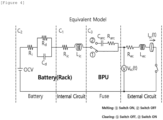
- FIG. 4 is an equivalent model circuit diagram in a battery system in a short-circuit state according to embodiments of the present invention.
- the processor 2000 in a short-circuit current prediction apparatus may calculate an equivalent circuit representing electrical characteristics of a battery system, thereby predicting a short-circuit current in the battery system.
- the short-circuit current prediction apparatus may obtain a short-circuit current prediction model reflecting internal circuit characteristics, electrical characteristics of the battery, and electrical characteristics of a fuse, based on a RL series circuit reflecting characteristics of a short-circuit state in a DC circuit model. Accordingly, the short-circuit current prediction apparatus may predict a short-circuit current value in a battery system by using the obtained short-circuit current prediction model.
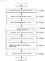
- FIG. 5 is a flowchart of a short-circuit current prediction method according to embodiments of the present invention.
- the processor 2000 may obtain a short-circuit current prediction model in a battery system reflecting internal circuit characteristics of the battery, electrical characteristics of the battery, and electrical characteristics of a fuse in a battery protection unit, based on a RL series circuit reflecting characteristics of a short-circuit state in a DC circuit.
- the processor 2000 may predict a magnitude of the short-circuit current generated according to a magnitude of a specific voltage, based on the obtained short-circuit current prediction model.
- the processor 2000 may obtain an internal equivalent circuit of a battery from a RL series circuit reflecting a characteristics of the short-circuit state in a DC circuit S1000. The step of obtaining the internal equivalent circuit will be described in more detail below.
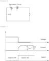
- FIG. 6 is an internal equivalent circuit diagram of a short-circuit current prediction apparatus according to embodiments of the present invention.
- an internal equivalent circuit applied to the short-circuit current prediction apparatus may include an RL series circuit.
- the internal equivalent circuit of a battery system may be a circuit representing electrical characteristics in the battery system based on a RL series circuit that effectively shows characteristics of a short-circuit state in a DC circuit.
- the internal equivalent circuit may be configured in a form in which a voltage (OCV), a resistor (R), an inductor (L), and a switch (S) are connected in series.
- the voltage may be an open circuit voltage (OCV)
- the resistor R may have an internal resistance value Ric
- the inductor L may have an internal inductance value Lic.
- the RL circuit applied to the short-circuit current prediction apparatus may be the same as the circuit used in a conventional battery protection unit to obtain the maximum short-circuit current.
- the maximum current value I max may be determined by a magnitude of the resistance R i and the open circuit voltage OCV of the battery.
- the inductor L may indicate a characteristic of a maximum current flowing in the circuit.
- FIG. 7 is a graph illustrating a voltage-current characteristic according to switch control in an internal equivalent circuit according to embodiments of the present invention.
- the voltage in the internal equivalent circuit may be kept constant and the current may not flow.
- the processor 2000 in the short-circuit current prediction apparatus may obtain a first equivalent circuit reflecting electrical characteristics of the battery.
- a method of obtaining the first equivalent circuit will be described below in more detail with reference to FIG. 8 .
- FIG. 8 is a first equivalent circuit diagram reflecting electrical characteristics of a battery according to embodiments of the present invention.
- the processor 2000 may obtain a first equivalent circuit reflecting electrical characteristics of a battery in the battery system S2000.
- the first equivalent circuit may include a circuit in which a first resistor (R i ) representing mechanical properties of the battery and a second resistor (R d ) and a capacitor (C d ) connected in parallel representing chemical properties of the battery are connected.
- the second resistor R d and the capacitor C d may be connected in parallel, which may be connected in series with the first resistor Ri.
- the first equivalent circuit may reflect mechanical and chemical properties of a battery in a battery system.
- the processor 2000 may obtain a second equivalent circuit in consideration of electrical characteristics of a fuse in a battery protection unit S3000. A method of obtaining the second equivalent circuit will be described in more detail below with reference to FIG. 9 .
- FIG. 9 is a second equivalent circuit diagram reflecting electrical characteristics of a fuse in a battery protection unit according to embodiments of the present invention.
- the processor 2000 may obtain a second equivalent circuit reflecting electrical characteristics of a fuse in a battery protection unit of a battery system.
- characteristics of voltage and current may change based on occurrence of a short circuit due to an arc. Accordingly, a state of the fuse may be changed from a first state (melting) to a second state (clearing) based on the occurrence of a short circuit.
- the first state may be a state in which a conductor starts to melt by heat generated inside the fuse before an arc is generated
- the second state may be a state in which an arc is generated and the conductor is melted so that a current flows into the air.
- the processor 2000 in the short-circuit current prediction apparatus may obtain a second equivalent circuit that causes a state transition to occur according to a position of the switch.
- the second equivalent circuit may include a switch and a circuit in which the resistor R arc and the capacitor C arc are connected in series.
- the second equivalent circuit may be designed so that the capacitor C arc and the resistor R arc components are reflected or not reflected in the circuit depending on to which state the switch is controlled.
- the processor 2000 may obtain a short-circuit current prediction model based on the obtained internal equivalent circuit, the first equivalent circuit, and the second equivalent circuit S4000.
- the processor 2000 may formulate the first equivalent circuit S4100.
- a method of formulating the first equivalent circuit will be described in more detail below with reference to FIG. 10 .
- FIG. 10 shows voltage-current graphs of the first equivalent circuit according to a state of a battery according to embodiments of the present invention.
- the voltage of the battery may be rapidly reduced by a first resistor R i .
- the capacitor C d in the first equivalent circuit may operate as if conducting in a transient state.
- only the series-connected first resistor (R i ) component may be considered in the first equivalent circuit as shown in Equations 2 and 3 below.
- the second resistance R d may increase. Accordingly, the capacitor C d may operate similarly to an instance in which the conducted current is decreased and then opened.
- the processor 2000 in the short-circuit current prediction apparatus may obtain a first equation in which all physical and chemical characteristics according to the transient state and the stationary state of the battery are reflected, as shown in Equation 4 below.
- the first formula may be a formula in which electrical characteristics of not only series-connected battery cells but also parallel-connected battery modules, battery racks, and battery systems are reflected.
- the CCV may be a closed circuit voltage
- the battery module and the battery system may be used interchangeably with terms such as a battery pack and a battery bank, respectively.
- CCV OCV ⁇ R i I t ⁇ 1 C ⁇ I t ⁇ V d R d dt
- the processor 2000 may formulate the second equivalent circuit S4300. A method of formulating the second equivalent circuit will be described in more detail below with reference to FIG. 11 .
- FIG. 11 shows voltage-current graphs in a first state or in a second state according to a switching state in a second equivalent circuit according to embodiments of the present invention.
- a state of the fuse may be transitioned according to a state of the switch.
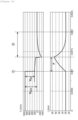
- FIG. 12 shows voltage-current change graphs according to a short-circuit state of a fuse according to embodiments of the present invention.
- a first state when the switch is in 1 state, a first state (Melting) may be represented.
- a second state (Clearing) may be represented.
- a counter electromotive force (V peak ) may be generated in the second equivalent circuit.
- the counter electromotive force may be generated as shown in Equation 5 below by an inductance component in the second equivalent circuit.
- the switch may be switched when a state transition occurs from the first state to the second state based on a preset threshold value.
- the threshold value is a value obtained by multiplying a square of the current (I 2 ) by the time (t), and may be calculated based on a data sheet of a fuse or short circuit occurrence experimental data.
- the processor 2000 may reflect the formulated first equivalent circuit and the second equivalent circuit in the internal equivalent circuit, and obtain a short-circuit current prediction model that may be provided in a first mode or a second mode according to a state of the fuse in a short-circuit occurrence (S4500).
- the short-circuit current prediction model may be a model that represents values of short-circuit voltage and short-circuit current in mathematical expressions, wherein the short-circuit voltage and the short-circuit current are generated in a battery system according to a state of a fuse when the short circuit occurs.
- the processor 2000 may combine the internal equivalent circuit, and the formulated first and the second equivalent circuits according to a short-circuit state of the fuse.
- the processor 2000 may obtain a short-circuit current prediction model in a first mode by reflecting the internal equivalent circuit in the first equivalent circuit equation representing electrical characteristics of the battery in a transient state and the second equivalent circuit equation representing electrical characteristics of the fuse in a first state (melting).
- the short-circuit current prediction model in the first mode may be expressed as Equation 6 below.
- V sc t OCV ⁇ R i + R ic I t ⁇ L ic dI t dt
- I SC t OCV R i + R ic + R ec 1 ⁇ e R i + R ic + R ec L ic + L ec t
- the processor 2000 may obtain a short-circuit current prediction model in a second mode by reflecting the internal equivalent circuit in the first equivalent circuit equation representing electrical characteristics of the battery in a steady state and the second equivalent circuit equation representing electrical characteristics of the fuse in a second state (clearing).
- V SC t OCV ⁇ R i + R ic I t ⁇ L ic dI t dt ⁇ 1 C arc ⁇ I t dt ⁇ R arc I t I SC t ⁇ V fuse R arc e ⁇ 1 R arc C arc t
- the processor 2000 may calculate parameter values of the short-circuit current prediction model in the first mode or the second mode to predict the short-circuit current according to the battery voltage S5000.
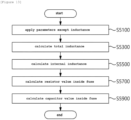
- FIG. 13 is a flowchart for calculating parameter values of a short-circuit current prediction model according to embodiments of the present invention.
- the processor 2000 may apply parameter values except the inductance L in the short-circuit current prediction model by using previously acquired short-circuit occurrence experimental data S5100.
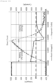
- FIG. 14 is a graph showing a short circuit occurrence experiment in which a voltage-current change of the battery is measured according to a state of the fuse, according to embodiments of the present invention.
- the short-circuit occurrence experiment data may be data obtained by pre-simulating a short-circuit current in a battery system according to a state of a fuse.
- the processor 2000 may obtain values of parameters, such as voltage, resistance, and capacitor, except a total inductance L total , from short-circuit occurrence experimental data, and apply the values to the short-circuit current prediction model.
- the processor 2000 may extract a value of the remaining unknown inductance L from the short-circuit current prediction model to which the parameter values are applied S5300.
- the inductance L may be calculated using curve fitting from a characteristic curve of the short-circuit current in section A illustrated in FIG. 12 .
- the inductance L may be a total inductance L total value obtained by adding an internal inductance L ic of the battery and an external inductance L ec .
- the processor 2000 may use a characteristic of the short-circuit voltage V sc that varies depending on a ratio of the inductance L, as shown in Equation 8 and Equation 9 below, to calculate an internal inductance L ic S5500.
- V sc L ec L total ⁇ OCV
- the processor 2000 may calculate the resistor value R arc inside the fuse with reference to Equation 10 below S5700.
- R arc V sc I sc
- the processor 2000 may apply a magnitude (V peak ) of a voltage at which a counter electromotive force occurs and the short-circuit current value (I sc ) to the short-circuit current prediction model, to calculate the resistance value inside the fuse.
- V peak a magnitude of a voltage at which a counter electromotive force occurs
- I sc short-circuit current value
- the processor 2000 may extract a value of the capacitor C arc , which is one remaining unknown in the short-circuit current prediction model S5900.
- the processor 2000 may extract a value of the capacitor C arc using curve fitting.
- the processor 2000 may calculate all of the parameters of the short-circuit current prediction model in the first mode or in the second mode based on the previously acquired short-circuit occurrence experimental data. Thus, it is possible to accurately predict the short-circuit current reflecting both electrical characteristics of the battery and the electrical characteristics of the fuse in the battery system.
- the short-circuit current prediction apparatus and method may derive an internal equivalent circuit of the battery that reflects a short circuit condition in a DC, derive a first equivalent circuit in consideration of electrical characteristics of the battery, derive a second equivalent circuit in consideration of electrical characteristics of the fuse, obtain a short-circuit current prediction model by reflecting the first equivalent circuit and the second equivalent circuit based on the internal equivalent circuit, and predict the short-circuit current according to a battery voltage using the short-circuit current prediction model.
- a block or apparatus corresponds to a method step or feature of a method step.
- aspects described in the context of a method may also represent a feature of a corresponding block or item or a corresponding apparatus.
- Some or all of the method steps may be performed by (or using) a hardware device, such as, for example, a microprocessor, a programmable computer, or an electronic circuit. In some embodiments, one or more of the most important method steps may be performed by such an apparatus.
Landscapes
- Physics & Mathematics (AREA)
- General Physics & Mathematics (AREA)
- Engineering & Computer Science (AREA)
- Power Engineering (AREA)
- Secondary Cells (AREA)
- Testing Electric Properties And Detecting Electric Faults (AREA)
- Tests Of Electric Status Of Batteries (AREA)
- Control Of El Displays (AREA)
- Emergency Protection Circuit Devices (AREA)
- Testing Of Short-Circuits, Discontinuities, Leakage, Or Incorrect Line Connections (AREA)
- Protection Of Static Devices (AREA)
Abstract
Description
- This application claims priority to and the benefit of
Korean Patent Application No.10-2021-0130860 filed in the Korean Intellectual Property Office on October 01, 2021 - The present invention relates to a short-circuit current prediction apparatus and method, and more particularly, to a short-circuit current prediction apparatus and method for predicting in advance a magnitude of a short-circuit current generated in a battery system.
- An energy storage system relates to renewable energy, a battery that stores electric power, and a power grid. Recently, as a spread of smart grid and renewable energy is expanding and efficiency and stability of the power system are emphasized, a demand for energy storage systems for power supply and demand control and power quality improvement is increasing. Depending on a purpose of use, energy storage systems may have different outputs and capacities. In order to configure a large-capacity energy storage system, a plurality of battery systems may be connected.
- Meanwhile, a battery condition management is essential for continuous energy storage system (ESS) service.
- For this, the energy storage system requires information on the battery system, such as a voltage of the battery and whether a battery fuse is blown. However, since the battery system is provided in a structure in which a plurality of battery cells and various elements are connected, it is not easy to determine whether a problem is with the battery fuse or other elements when charging or discharging is not performed. Furthermore, when predicting short-circuit current, electrical characteristics of the battery are not considered and a magnitude of the short-circuit current blocked by the fuse cannot be predicted.
- Accordingly, in order to design a battery protection system, an experiment for measuring a maximum short-circuit current is essentially performed. However, this has disadvantages that are accompanied by problems of high cost and high risk.
- In order to solve the problem, an object of the present invention is to provide a high-efficiency and low-cost short-circuit current prediction apparatus that can determine a voltage of a battery and whether a fuse is blown.
- In order to solve the problem, another object of the present invention is to a method for predicting a short-circuit current with high efficiency and low cost that can determine a voltage of a battery and whether a fuse is blown.
- In order to achieve the objective of the present disclosure, an apparatus for predicting a short-circuit current in a battery system including a battery and a fuse for protecting the battery may comprise at least one processor; and a memory configured to store at least one instruction executed by the at least one processor, wherein the at least one instruction includes an instruction to derive an internal equivalent circuit of the battery that reflects a short circuit condition in a DC(Direct Current) circuit; an instruction to derive a first equivalent circuit in consideration of one or more electrical characteristics of the battery; an instruction to derive a second equivalent circuit in consideration of one or more electrical characteristics of the fuse; an instruction to obtain a short-circuit current prediction model by reflecting the first equivalent circuit and the second equivalent circuit based on the internal equivalent circuit; and an instruction to predict the short-circuit current according to a battery voltage using the short-circuit current prediction model.
- The first equivalent circuit may include a circuit in which a first resistor and a second resistor are connected in series in the battery, the second resistor being connected in parallel with a capacitor.
- The second equivalent circuit may include a switch and a circuit in which a resistor and a capacitor of the fuse are connected in series.
- The switch may represent a first state in which a conductor starts to melt by heat generated inside the fuse before an arc occurs or a second state in which the conductor melted due to occurrence of an arc and a current flows into the air, according to an on/off state of the switch.
- The instruction to obtain the short-circuit current prediction model may include an instruction to formulate the first equivalent circuit; an instruction to formulate the second equivalent circuit; and an instruction to obtain the short-circuit current prediction model according to the first state or the second state by reflecting the formulated first equivalent circuit and the second equivalent circuit in the internal equivalent circuit and using short-circuit occurrence experimental data.
- The internal equivalent circuit may include an internal resistor and an internal inductor of the battery based on an RL circuit.
- The short-circuit current prediction model in the first state may include one or more mechanical characteristics of the battery in a transient state and the short-circuit current prediction model in the second state may include one or more mechanical characteristics of the battery in the transient state and one or more chemical characteristics of the battery in a stationary state.
- According to another embodiment of the present disclosure, a method for predicting a short-circuit current in a battery system including a battery and a fuse for protecting the battery may comprise deriving an internal equivalent circuit of the battery that reflects a short circuit condition in a DC(Direct Current) circuit; deriving a first equivalent circuit in consideration of one or more electrical characteristics of the battery; deriving a second equivalent circuit in consideration of one or more electrical characteristics of the fuse; obtaining a short-circuit current prediction model by reflecting the first equivalent circuit and the second equivalent circuit based on the internal equivalent circuit; and predicting a short-circuit current according to a battery voltage using the short-circuit current prediction model.
- The first equivalent circuit may include a circuit in which a first resistor and a second resistor are connected in series in the battery, the second resistor being connected in parallel with a capacitor.
- The second equivalent circuit may include a switch and a circuit in which a resistor and a capacitor of the fuse are connected in series.
- The switch may represent a first state in which a conductor starts to melt by heat generated inside the fuse before an arc occurs or a second state in which the conductor melted due to occurrence of an arc and a current flows into the air, according to an on/off state of the switch.
- The obtaining the short-circuit current prediction model may include formulating the first equivalent circuit; formulating the second equivalent circuit; and obtaining the short-circuit current prediction model according to the first state or the second state by reflecting the formulated first equivalent circuit and the second equivalent circuit in the internal equivalent circuit and using short-circuit occurrence experimental data.
- The internal equivalent circuit may include an internal resistor and an internal inductor of the battery based on an RL circuit.
- The short-circuit current prediction model in the first state may include one or more mechanical characteristics of the battery in a transient state and the short-circuit current prediction model in the second state may include one or more mechanical characteristics of the battery in the transient state and one or more chemical characteristics of the battery in a stationary state.
- According to embodiments of the present disclosure, the short-circuit current prediction apparatus and method may derive an internal equivalent circuit of the battery that reflects a short circuit condition in a DC, derive a first equivalent circuit in consideration of electrical characteristics of the battery, derive a second equivalent circuit in consideration of electrical characteristics of the fuse, obtain a short-circuit current prediction model by reflecting the first equivalent circuit and the second equivalent circuit based on the internal equivalent circuit, and predict the short-circuit current according to a battery voltage using the short-circuit current prediction model. Thus, high-precision short-circuit current prediction is possible in units of battery modules, racks, and systems (banks) in consideration of both mechanical and chemical characteristics of a parallel-connected battery system and based on previously acquired short-circuit occurrence experimental data, thereby providing a high-efficiency and low-cost short-circuit current prediction apparatus and method that can be used to determine a maximum number of parallel connections of batteries while developing a battery system, and thus, reducing a number of short-circuit occurrence experiments and preventing a delay of development schedule.
-
-
FIG. 1 is a schematic circuit diagram of a short circuit accident of a battery. -
FIG. 2 is a flowchart illustrating a conventional design process of a battery protection unit. -
FIG. 3 is a block diagram of a short-circuit current prediction apparatus according to embodiments of the present invention. -
FIG. 4 is an equivalent model circuit diagram in a battery system in a short-circuit state according to embodiments of the present invention. -
FIG. 5 is a flowchart of a short-circuit current prediction method according to embodiments of the present invention. -
FIG. 6 is an internal equivalent circuit diagram of a short-circuit current prediction apparatus according to embodiments of the present invention. -
FIG. 7 is a graph illustrating a voltage-current characteristic according to switch control in an internal equivalent circuit according to embodiments of the present invention. -
FIG. 8 is a first equivalent circuit diagram reflecting electrical characteristics of a battery according to embodiments of the present invention. -
FIG. 9 is a second equivalent circuit diagram reflecting electrical characteristics of a fuse in a battery protection unit according to embodiments of the present invention. -
FIG. 10 shows voltage-current graphs of the first equivalent circuit according to a state of a battery according to embodiments of the present invention. -
FIG. 11 shows voltage-current graphs in a first state or a second state according to a switching state in a second equivalent circuit according to embodiments of the present invention. -
FIG. 12 shows voltage-current change graphs according to a short-circuit state of a fuse according to embodiments of the present invention. -
FIG. 13 is a flowchart for calculating parameter values of a short-circuit current prediction model according to embodiments of the present invention. -
FIG. 14 is a graph showing a short circuit occurrence experiment in which a voltage-current change of the battery is measured according to a state of the fuse, according to embodiments of the present invention.- 1000:
- memory
- 2000:
- processor
- 3000:
- transceiver
- 4000:
- input interface
- 5000:
- output interface
- 6000:
- storage device
- 7000:
- bus
- The present invention may be modified in various forms and have various embodiments, and specific embodiments thereof are shown by way of example in the drawings and will be described in detail below. It should be understood, however, that there is no intent to limit the present invention to the specific embodiments, but on the contrary, the present invention is to cover all modifications, equivalents, and alternatives falling within the spirit and technical scope of the present invention. Like reference numerals refer to like elements throughout the description of the figures.
- It will be understood that, although the terms such as first, second, A, B, and the like may be used herein to describe various elements, these elements should not be limited by these terms. These terms are only used to distinguish one element from another. For example, a first element could be termed a second element, and, similarly, a second element could be termed a first element, without departing from the scope of the present invention. As used herein, the term "and/or" includes combinations of a plurality of associated listed items or any of the plurality of associated listed items.
- It will be understood that when an element is referred to as being "coupled" or "connected" to another element, it can be directly coupled or connected to the other element or an intervening element may be present. In contrast, when an element is referred to as being "directly coupled" or "directly connected" to another element, there is no intervening element present.
- Terms used in the present application are used only to describe specific embodiments, and are not intended to limit the present invention. A singular form includes a plural form if there is no clearly opposite meaning in the context. In the present application, it should be understood that the term "include" or "have" indicates that a feature, a number, a step, an operation, a component, a part or the combination thereof described in the specification is present, but does not exclude a possibility of presence or addition of one or more other features, numbers, steps, operations, components, parts or combinations thereof, in advance.
- Unless otherwise defined, all terms used herein, including technical and scientific terms, have the same meanings as commonly understood by one skilled in the art to which the present invention belongs. It will be further understood that terms, such as those defined in commonly used dictionaries, should be interpreted as having meanings that are consistent with their meanings in the context of the relevant art and will not be interpreted in an idealized or overly formal sense unless expressly so defined herein.
- Hereinafter, exemplary embodiments of the present invention will be described in detail with reference to the accompanying drawings.
-
FIG. 1 is a schematic circuit diagram of a short circuit accident of a battery. - Referring to
FIG. 1 , a conventional battery protection device protects a battery from a short-circuit current by controlling an on/off operation of a fuse when a short-circuit accident occurs. Here, the short circuit accident may be an accident in which the positive and negative poles of the battery are connected and an overcurrent flows. - In general, a conventional battery protection device predicts a maximum short-circuit current in a transient state by considering only a basic RL equivalent circuit in which a basic resistor (R) and an inductor (L) are connected in series when calculating the short-circuit current.
- In other words, the conventional battery protection device does not consider any electrical characteristics of the battery when calculating the short-circuit current in the battery system, and also does not consider a short-circuit current blocked by a fuse. Accordingly, the conventional battery protection device has a disadvantage in that a large error occurs when calculating the maximum short-circuit current, thereby causing a damage to the battery and reducing reliability.
- Accordingly, in the prior art, a number of short-circuit occurrence experiments were separately conducted in order to calculate the maximum short-circuit current that can be cut off by operation control of a fuse before designing a battery protection device.
-
FIG. 2 is a flowchart illustrating a conventional design process of a battery protection device. - Referring to
FIG. 2 , a conventional battery protection device predicts a maximum short-circuit current based on a magnitude of a short-circuit current calculated through a basic RL equivalent circuit, and checks if short-circuit occurrence experimental data performed in advance exists for the predicted maximum short-circuit current value (S100). Then, the maximum short-circuit current value is the confirmed by checking if a short circuit has occurred according to the corresponding short-circuit current value (S200). - On the other hand, if there is no experimental data previously conducted for the predicted maximum short-circuit current value, a user performs a short-circuit occurrence experiment for the assumed maximum short-circuit current (S300). Furthermore, it is checked whether the short-circuit occurrence is a controllable short-circuit current by the fuse, and the maximum short-circuit current value is determined based on experimental results and is reflected in the conventional battery protection device.
- However, the conventional design method for battery protection requires a long time and a high cost because a number of experiments are required to calculate an optimal short-circuit current value.
- Accordingly, the present invention provides an equivalent circuit model in consideration of electrical characteristics of the battery, internal circuit characteristics, and electrical characteristics of the fuse in a battery protection device (BPU), thereby predicting a high-precision short-circuit current value. Thus, the present invention provides a high-efficiency and low-cost short-circuit current prediction apparatus and method that reduces a number of short-circuit occurrence experiments performed when designing a protection device and prevents delays in a development schedule by being used to determine a maximum number of parallel connections of batteries during a development of a battery system.
-
FIG. 3 is a block diagram of a short-circuit current prediction apparatus according to embodiments of the present invention. - Referring to
FIG. 3 , a short-circuit current prediction apparatus according to embodiments of the present invention may predict in advance a magnitude of a short-circuit current generated in a battery system according to a magnitude of a battery voltage. - For example, the short-circuit current prediction apparatus may be used when designing a battery protection device in an energy storage system (ESS) to prevent a short-circuit accident occurring in a battery system in the energy storage system in advance.
- More specifically, the short-circuit current prediction apparatus predicts a short-circuit current value for each component in a battery system in which at least one battery rack or module is connected in series and parallel through a simulation, so that the short-circuit current value can be applied for a maximum value for controlling operation of a fuse in a battery protection device.
- In more details, the short-circuit current prediction apparatus according to embodiments of the present invention may include a
memory 1000 for storing at least one instruction, aprocessor 2000 for executing at least one instruction of the memory, atransceiver 3000, aninput interface 4000, anoutput interface 5000, and astorage device 6000. - According to embodiments, components (1000, 2000, 3000, 4000, 5000, 6000) included in the short-circuit current prediction apparatus may be connected by a
bus 7000 to communicate with each other. - Among components (1000, 2000, 3000, 4000, 5000, 6000) in the short-circuit current prediction apparatus, the
memory 1000 or thestorage device 6000 may be configured as at least one of a volatile storage medium and a nonvolatile storage medium. For example, thememory 1000 or thestorage device 6000 may be configured as at least one of a read only memory (ROM) and a random access memory (RAM) . - The
memory 1000 may include at least one instruction to be executed by theprocessor 2000 to be described later. - According to embodiments, the at least one instruction may include an instruction to derive an internal equivalent circuit of the battery that reflects a short circuit condition in a DC(direct current) circuit; a instruction to derive a first equivalent circuit in consideration of electrical characteristics of the battery; a instruction to derive a second equivalent circuit in consideration of electrical characteristics of the fuse; an instructions to obtain a short-circuit current prediction model by reflecting the first equivalent circuit and the second equivalent circuit based on the internal equivalent circuit; and an instructions to predict the short-circuit current according to a battery voltage using the short-circuit current prediction model.
- Here, the
processor 2000 may include a central processing unit (CPU), a graphics processing unit (GPU), or a dedicated processor on which a method according to embodiments of the present invention are performed. - As described above, the
processor 2000 may execute at least one program command stored in thememory 1000 . - Hereinafter, a method for predicting a short-circuit current executed by a processor in an apparatus for predicting a short-circuit current according to embodiments of the present invention will be described in detail with reference to
FIG. 4 . -
FIG. 4 is an equivalent model circuit diagram in a battery system in a short-circuit state according to embodiments of the present invention. - Referring to
FIG. 4 , theprocessor 2000 in a short-circuit current prediction apparatus may calculate an equivalent circuit representing electrical characteristics of a battery system, thereby predicting a short-circuit current in the battery system. - According to an embodiment, the short-circuit current prediction apparatus according to the present invention may obtain a short-circuit current prediction model reflecting internal circuit characteristics, electrical characteristics of the battery, and electrical characteristics of a fuse, based on a RL series circuit reflecting characteristics of a short-circuit state in a DC circuit model. Accordingly, the short-circuit current prediction apparatus may predict a short-circuit current value in a battery system by using the obtained short-circuit current prediction model.
- In
FIG. 5 below, operations of theprocessor 2000 will be described in more detail in order. -
FIG. 5 is a flowchart of a short-circuit current prediction method according to embodiments of the present invention. - Referring to
FIGs. 4 and5 , theprocessor 2000 may obtain a short-circuit current prediction model in a battery system reflecting internal circuit characteristics of the battery, electrical characteristics of the battery, and electrical characteristics of a fuse in a battery protection unit, based on a RL series circuit reflecting characteristics of a short-circuit state in a DC circuit. - Thereafter, the
processor 2000 may predict a magnitude of the short-circuit current generated according to a magnitude of a specific voltage, based on the obtained short-circuit current prediction model. - In more detail, the
processor 2000 may obtain an internal equivalent circuit of a battery from a RL series circuit reflecting a characteristics of the short-circuit state in a DC circuit S1000. The step of obtaining the internal equivalent circuit will be described in more detail below. -
FIG. 6 is an internal equivalent circuit diagram of a short-circuit current prediction apparatus according to embodiments of the present invention. - Referring to
FIG. 6 , an internal equivalent circuit applied to the short-circuit current prediction apparatus may include an RL series circuit. - More specifically, the internal equivalent circuit of a battery system may be a circuit representing electrical characteristics in the battery system based on a RL series circuit that effectively shows characteristics of a short-circuit state in a DC circuit. For example, the internal equivalent circuit may be configured in a form in which a voltage (OCV), a resistor (R), an inductor (L), and a switch (S) are connected in series. Here, the voltage may be an open circuit voltage (OCV), the resistor R may have an internal resistance value Ric, and the inductor L may have an internal inductance value Lic.
- Here, the RL circuit applied to the short-circuit current prediction apparatus may be the same as the circuit used in a conventional battery protection unit to obtain the maximum short-circuit current.
- For example, in the internal equivalent circuit, the maximum current value Imax may be determined by a magnitude of the resistance Ri and the open circuit voltage OCV of the battery. In addition, the inductor L may indicate a characteristic of a maximum current flowing in the circuit.
-
FIG. 7 is a graph illustrating a voltage-current characteristic according to switch control in an internal equivalent circuit according to embodiments of the present invention. - Referring to
FIG. 7 , when the internal equivalent circuit is in open state, that is, when the switch is in OFF state, the voltage in the internal equivalent circuit may be kept constant and the current may not flow. - On the other hand, when the internal equivalent circuit is closed, that is, when the switch is ON, the voltage in the internal equivalent circuit is reduced to 0 by the resistor, and thus a current may flow. Here, the maximum current value (Imax) flowing through the internal equivalent circuit may be expressed as in
Equation 1 below.
- Imax: Maximum current value flowing through internal equivalent circuit
- OCV: Open Circuit Voltage
- R: short circuit resistance
- Thereafter, the
processor 2000 in the short-circuit current prediction apparatus according to embodiments of the present invention may obtain a first equivalent circuit reflecting electrical characteristics of the battery. A method of obtaining the first equivalent circuit will be described below in more detail with reference toFIG. 8 . -
FIG. 8 is a first equivalent circuit diagram reflecting electrical characteristics of a battery according to embodiments of the present invention. - Referring to
FIG. 8 , theprocessor 2000 may obtain a first equivalent circuit reflecting electrical characteristics of a battery in the battery system S2000. - More specifically, the first equivalent circuit may include a circuit in which a first resistor (Ri) representing mechanical properties of the battery and a second resistor (Rd) and a capacitor (Cd) connected in parallel representing chemical properties of the battery are connected. Here, the second resistor Rd and the capacitor Cd may be connected in parallel, which may be connected in series with the first resistor Ri. Accordingly, the first equivalent circuit may reflect mechanical and chemical properties of a battery in a battery system.
- Referring back to
FIG. 5 , theprocessor 2000 may obtain a second equivalent circuit in consideration of electrical characteristics of a fuse in a battery protection unit S3000. A method of obtaining the second equivalent circuit will be described in more detail below with reference toFIG. 9 . -
FIG. 9 is a second equivalent circuit diagram reflecting electrical characteristics of a fuse in a battery protection unit according to embodiments of the present invention. - Referring to
FIG. 9 , theprocessor 2000 may obtain a second equivalent circuit reflecting electrical characteristics of a fuse in a battery protection unit of a battery system. - In general, in a battery system, characteristics of voltage and current may change based on occurrence of a short circuit due to an arc. Accordingly, a state of the fuse may be changed from a first state (melting) to a second state (clearing) based on the occurrence of a short circuit.
- Here, the first state may be a state in which a conductor starts to melt by heat generated inside the fuse before an arc is generated, and the second state may be a state in which an arc is generated and the conductor is melted so that a current flows into the air.
- Accordingly, in order to implement the fusing characteristic of the fuse, the
processor 2000 in the short-circuit current prediction apparatus according to embodiments of the present invention may obtain a second equivalent circuit that causes a state transition to occur according to a position of the switch. - More specifically, the second equivalent circuit may include a switch and a circuit in which the resistor Rarc and the capacitor Carc are connected in series. Here, the second equivalent circuit may be designed so that the capacitor Carc and the resistor Rarc components are reflected or not reflected in the circuit depending on to which state the switch is controlled.
- Referring back to
FIG. 5 , theprocessor 2000 may obtain a short-circuit current prediction model based on the obtained internal equivalent circuit, the first equivalent circuit, and the second equivalent circuit S4000. - More specifically, the
processor 2000 may formulate the first equivalent circuit S4100. A method of formulating the first equivalent circuit will be described in more detail below with reference toFIG. 10 . -
FIG. 10 shows voltage-current graphs of the first equivalent circuit according to a state of a battery according to embodiments of the present invention. - Referring to
FIG. 10 , in the first equivalent circuit, when a change in the battery voltage occurs, a current may flow in the capacitor Cd. - According to an embodiment, when the battery is in a transient state, the voltage of the battery may be rapidly reduced by a first resistor Ri. Accordingly, the capacitor Cd in the first equivalent circuit may operate as if conducting in a transient state. In other words, when the battery is in a transient state, only the series-connected first resistor (Ri) component may be considered in the first equivalent circuit as shown in
Equations 2 and 3 below.

According to another embodiment, when the battery is in a steady state, since charges are accumulated in the capacitor Cd in the first equivalent circuit, the second resistance Rd may increase. Accordingly, the capacitor Cd may operate similarly to an instance in which the conducted current is decreased and then opened. - Accordingly, the
processor 2000 in the short-circuit current prediction apparatus according to embodiments of the present invention may obtain a first equation in which all physical and chemical characteristics according to the transient state and the stationary state of the battery are reflected, as shown in Equation 4 below. In other words, the first formula may be a formula in which electrical characteristics of not only series-connected battery cells but also parallel-connected battery modules, battery racks, and battery systems are reflected. Here, the CCV may be a closed circuit voltage, and the battery module and the battery system may be used interchangeably with terms such as a battery pack and a battery bank, respectively.
- CCV:
- Closed Circuit Voltage
- OCV:
- Open Circuit Voltage
- Ri, Rd:
- first resistance, second resistance
- I:
- current
- Vd:
- voltage across second resistor
- C:
- capacitance
- Referring back to
FIG. 5 , theprocessor 2000 may formulate the second equivalent circuit S4300. A method of formulating the second equivalent circuit will be described in more detail below with reference toFIG. 11 . -
FIG. 11 shows voltage-current graphs in a first state or in a second state according to a switching state in a second equivalent circuit according to embodiments of the present invention. - Referring to
FIG. 11 , in the second equivalent circuit, a state of the fuse may be transitioned according to a state of the switch. -
FIG. 12 shows voltage-current change graphs according to a short-circuit state of a fuse according to embodiments of the present invention. - Referring to
FIGs. 11 and12 , in the second equivalent circuit according to an exemplary embodiment, when the switch is in ① state, a first state (Melting) may be represented. - More specifically, in the first state, since components of the capacitor Carc and the resistor Rarc in the circuit are not reflected, a voltage may not be applied and a current may flow.
- In the second equivalent circuit according to another embodiment, when the switch is in (2) state, a second state (Clearing) may be represented.
- More specifically, in the second state, charges may be accumulated in the capacitor Carc, so that the current may decrease. When the accumulation of the capacitor Carc is completed, the second equivalent circuit may be opened.
- Here, a counter electromotive force (Vpeak) may be generated in the second equivalent circuit. The counter electromotive force may be generated as shown in Equation 5 below by an inductance component in the second equivalent circuit.

- Vpeak:
- counter electromotive force
- Rarc:
- resistance inside fuse
- Here, the switch may be switched when a state transition occurs from the first state to the second state based on a preset threshold value. For example, the threshold value is a value obtained by multiplying a square of the current (I2) by the time (t), and may be calculated based on a data sheet of a fuse or short circuit occurrence experimental data.
- Referring back to
FIG. 5 , theprocessor 2000 may reflect the formulated first equivalent circuit and the second equivalent circuit in the internal equivalent circuit, and obtain a short-circuit current prediction model that may be provided in a first mode or a second mode according to a state of the fuse in a short-circuit occurrence (S4500). Here, the short-circuit current prediction model may be a model that represents values of short-circuit voltage and short-circuit current in mathematical expressions, wherein the short-circuit voltage and the short-circuit current are generated in a battery system according to a state of a fuse when the short circuit occurs. - A method of obtaining the short-circuit current prediction model will be described in more detail. The
processor 2000 may combine the internal equivalent circuit, and the formulated first and the second equivalent circuits according to a short-circuit state of the fuse. - According to an embodiment, the
processor 2000 may obtain a short-circuit current prediction model in a first mode by reflecting the internal equivalent circuit in the first equivalent circuit equation representing electrical characteristics of the battery in a transient state and the second equivalent circuit equation representing electrical characteristics of the fuse in a first state (melting). - The short-circuit current prediction model in the first mode may be expressed as Equation 6 below.

- Vsc:
- short-circuit voltage in first mode
- Isc:
- short-circuit current in first mode
- Ri:
- first resistance
- Ric:
- internal resistance
- Rec:
- external resistance
- Lic:
- internal inductance
- Lec:
- external inductance
- Carc:
- capacitance inside fuse
- Rarc:
- resistance inside fuse
- The
processor 2000 may obtain a short-circuit current prediction model in a second mode by reflecting the internal equivalent circuit in the first equivalent circuit equation representing electrical characteristics of the battery in a steady state and the second equivalent circuit equation representing electrical characteristics of the fuse in a second state (clearing). - The short-circuit current prediction model in the second mode may be expressed as equation 7 below.

- Vsc:
- short-circuit voltage in second mode
- Isc:
- short-circuit current in second mode
- Ri:
- first resistance
- Ric:
- internal resistance
- Lic:
- internal inductance
- Lec:
- external inductance
- Carc:
- capacitance inside fuse
- Rarc:
- resistance inside fuse
- Vfuse:
- voltage inside fuse
- Thereafter, the
processor 2000 may calculate parameter values of the short-circuit current prediction model in the first mode or the second mode to predict the short-circuit current according to the battery voltage S5000. - A method of calculating the parameter values of the short-circuit current prediction model will be described in more detail below with reference to
FIG. 13 . -
FIG. 13 is a flowchart for calculating parameter values of a short-circuit current prediction model according to embodiments of the present invention. - Referring to
FIG. 13 , theprocessor 2000 may apply parameter values except the inductance L in the short-circuit current prediction model by using previously acquired short-circuit occurrence experimental data S5100. -
FIG. 14 is a graph showing a short circuit occurrence experiment in which a voltage-current change of the battery is measured according to a state of the fuse, according to embodiments of the present invention. - Referring to
FIGs. 13 and14 , the short-circuit occurrence experiment data may be data obtained by pre-simulating a short-circuit current in a battery system according to a state of a fuse. - The
processor 2000 may obtain values of parameters, such as voltage, resistance, and capacitor, except a total inductance Ltotal, from short-circuit occurrence experimental data, and apply the values to the short-circuit current prediction model. - Thereafter, the
processor 2000 may extract a value of the remaining unknown inductance L from the short-circuit current prediction model to which the parameter values are applied S5300. For example, the inductance L may be calculated using curve fitting from a characteristic curve of the short-circuit current in section A illustrated inFIG. 12 . Here, the inductance L may be a total inductance Ltotal value obtained by adding an internal inductance Lic of the battery and an external inductance Lec. - More specifically, according to embodiments, in the case of a battery system, the value of the inductance L may have a dominant influence initially due to a high frequency component. Accordingly, the
processor 2000 may use a characteristic of the short-circuit voltage Vsc that varies depending on a ratio of the inductance L, as shown in Equation 8 and Equation 9 below, to calculate an internal inductance Lic S5500. Here, an external inductance Lec may be given as experimental data.
- Lec:
- battery external inductance
- Ltotal:
- total inductance in battery system
- Lic:
- battery internal inductance
- Thereafter, the
processor 2000 may calculate the resistor value Rarc inside the fuse with reference toEquation 10 below S5700.
- Isc:
- short-circuit current
- More specifically, according to the embodiments, the
processor 2000, based on previously acquired short-circuit occurrence experimental data, may apply a magnitude (Vpeak) of a voltage at which a counter electromotive force occurs and the short-circuit current value (Isc) to the short-circuit current prediction model, to calculate the resistance value inside the fuse. - Thereafter, the
processor 2000 may extract a value of the capacitor Carc, which is one remaining unknown in the short-circuit current prediction model S5900. For example, theprocessor 2000 may extract a value of the capacitor Carc using curve fitting. - In summary, the
processor 2000 may calculate all of the parameters of the short-circuit current prediction model in the first mode or in the second mode based on the previously acquired short-circuit occurrence experimental data. Thus, it is possible to accurately predict the short-circuit current reflecting both electrical characteristics of the battery and the electrical characteristics of the fuse in the battery system. - The short-circuit current prediction apparatus and method according to embodiments of the present invention have been described above.
- The short-circuit current prediction apparatus and method according to embodiments of the present invention may derive an internal equivalent circuit of the battery that reflects a short circuit condition in a DC, derive a first equivalent circuit in consideration of electrical characteristics of the battery, derive a second equivalent circuit in consideration of electrical characteristics of the fuse, obtain a short-circuit current prediction model by reflecting the first equivalent circuit and the second equivalent circuit based on the internal equivalent circuit, and predict the short-circuit current according to a battery voltage using the short-circuit current prediction model. Thus, high-precision short-circuit current prediction is possible in units of battery modules, racks, and systems (banks) in consideration of both mechanical and chemical characteristics of a parallel-connected battery system and based on previously acquired short-circuit occurrence experimental data, therby providing a high-efficiency and low-cost short-circuit current prediction apparatus and method that can be used to determine a maximum number of parallel connections of batteries while developing a battery system, and thus, reducing a number of short-circuit occurrence experiments and preventing a delay of development schedule.
- Although some aspects of the invention have been described in the context of the apparatus, it may also represent a description according to a corresponding method, wherein a block or apparatus corresponds to a method step or feature of a method step. Similarly, aspects described in the context of a method may also represent a feature of a corresponding block or item or a corresponding apparatus. Some or all of the method steps may be performed by (or using) a hardware device, such as, for example, a microprocessor, a programmable computer, or an electronic circuit. In some embodiments, one or more of the most important method steps may be performed by such an apparatus.
- In the forgoing, the present invention has been described with reference to the exemplary embodiment of the present invention, but those skilled in the art may appreciate that the present invention may be variously corrected and changed within the range without departing from the spirit and the area of the present invention described in the appending claims.

Claims (14)
- An apparatus for predicting a short-circuit current in a battery system including a battery and a fuse for protecting the battery, the apparatus comprising:at least one processor; anda memory configured to store at least one instruction executed by the at least one processor,wherein the at least one instruction includes:an instruction to derive an internal equivalent circuit of the battery that reflects a short circuit condition in a DC(Direct Current) circuit;an instruction to derive a first equivalent circuit in consideration of one or more electrical characteristics of the battery;an instruction to derive a second equivalent circuit in consideration of one or more electrical characteristics of the fuse;an instruction to obtain a short-circuit current prediction model by reflecting the first equivalent circuit and the second equivalent circuit based on the internal equivalent circuit; andan instruction to predict the short-circuit current according to a battery voltage using the short-circuit current prediction model.
- The apparatus of claim 1, wherein the first equivalent circuit includes a circuit in which a first resistor and a second resistor are connected in series in the battery, the second resistor being connected in parallel with a capacitor.
- The apparatus of claim 1, wherein the second equivalent circuit includes a switch and a circuit in which a resistor and a capacitor of the fuse are connected in series.
- The apparatus of claim 3, wherein the switch represents a first state in which a conductor starts to melt by heat generated inside the fuse before an arc occurs or a second state in which the conductor melted due to occurrence of an arc and a current flows into the air, according to on/off state of the switch.
- The apparatus of claim 4, wherein the instruction to obtain the short-circuit current prediction model includes:an instruction to formulate the first equivalent circuit;formulate the second equivalent circuit; andan instruction to obtain the short-circuit current prediction model according to the first state or the second state by reflecting the formulated first equivalent circuit and the second equivalent circuit in the internal equivalent circuit and using short-circuit occurrence experimental data.
- The apparatus of claim 1, wherein the internal equivalent circuit includes an internal resistor and an internal inductor of the battery based on an RL circuit.
- The apparatus of claim 5, wherein the short-circuit current prediction model in the first state includes one or more mechanical characteristics of the battery in a transient state, and
the short-circuit current prediction model in the second state includes one or more mechanical characteristics of the battery in the transient state and one or more chemical characteristics of the battery in a stationary state. - A method for predicting a short-circuit current in a battery system including a battery and a fuse for protecting the battery, the method comprising:deriving an internal equivalent circuit of the batterythat reflects a short circuit condition in a DC(Direct Current) circuit;deriving a first equivalent circuit in consideration of one or more electrical characteristics of the battery;deriving a second equivalent circuit in consideration of one or more electrical characteristics of the fuse;obtaining a short-circuit current prediction model by reflecting the first equivalent circuit and the second equivalent circuit based on the internal equivalent circuit; andpredicting a short-circuit current according to a battery voltage using the short-circuit current prediction model.
- The method of claim 8, wherein the first equivalent circuit includes a circuit in which a first resistor and a second resistor are connected in series in the battery, the second resistor being connected in parallel with a capacitor.
- The method of claim 8, wherein the second equivalent circuit includes a switch and a circuit in which a resistor and a capacitor of the fuse are connected in series.
- The method of claim 10, wherein the switch represents a first state in which a conductor starts to melt by heat generated inside the fuse before an arc occurs, or a second state in which the conductor melted due to occurrence of an arc and a current flows into the air, according to an on/off state of the switch.
- The method of claim 11, wherein the obtaining the short-circuit current prediction model includes:formulating the first equivalent circuit;formulating the second equivalent circuit; andobtaining the short-circuit current prediction model according to the first state or the second state by reflecting the formulated first equivalent circuit and the second equivalent circuit in the internal equivalent circuit and using short-circuit occurrence experimental data.
- The method of claim 8, wherein the internal equivalent circuit includes an internal resistor and an internal inductor of the battery based on an RL circuit.
- The method of claim 12, wherein the short-circuit current prediction model in the first state includes mechanical properties of the battery in a transient state, and
the short-circuit current prediction model in the second state includes one or more mechanical characteristics of the battery in a transient state and one or more chemical characteristics of the battery in a stationary state.
Applications Claiming Priority (2)
| Application Number | Priority Date | Filing Date | Title |
|---|---|---|---|
| KR1020210130860A KR102941173B1 (en) | 2021-10-01 | 2021-10-01 | Apparatus and method for detecting short-circuit current in battery system |
| PCT/KR2022/013339 WO2023054928A1 (en) | 2021-10-01 | 2022-09-06 | Short-circuit current prediction device and method |
Publications (3)
| Publication Number | Publication Date |
|---|---|
| EP4300110A1 true EP4300110A1 (en) | 2024-01-03 |
| EP4300110A4 EP4300110A4 (en) | 2024-11-06 |
| EP4300110B1 EP4300110B1 (en) | 2025-06-18 |
Family
ID=85780854
Family Applications (1)
| Application Number | Title | Priority Date | Filing Date |
|---|---|---|---|
| EP22876703.4A Active EP4300110B1 (en) | 2021-10-01 | 2022-09-06 | Short-circuit current prediction device and method |
Country Status (10)
| Country | Link |
|---|---|
| US (1) | US20240151778A1 (en) |
| EP (1) | EP4300110B1 (en) |
| JP (1) | JP7725601B2 (en) |
| KR (1) | KR102941173B1 (en) |
| CN (1) | CN117043614A (en) |
| AU (1) | AU2022356974A1 (en) |
| ES (1) | ES3034820T3 (en) |
| HU (1) | HUE071834T2 (en) |
| PL (1) | PL4300110T3 (en) |
| WO (1) | WO2023054928A1 (en) |
Cited By (1)
| Publication number | Priority date | Publication date | Assignee | Title |
|---|---|---|---|---|
| EP4550619A4 (en) * | 2023-06-30 | 2025-12-03 | Lg Energy Solution Ltd | BATTERY SYSTEM MANAGEMENT DEVICE AND METHOD FOR DETERMINING THE OPTIMAL NUMBER OF BATTERIES |
Families Citing this family (5)
| Publication number | Priority date | Publication date | Assignee | Title |
|---|---|---|---|---|
| CN116799741B (en) * | 2023-05-24 | 2024-03-26 | 华斗数字科技(上海)有限公司 | Precision equipment short-circuit monitoring protection method and system based on slope detection |
| CN116679236B (en) * | 2023-06-01 | 2024-05-17 | 中铁一局集团电务工程有限公司 | LSM-based subway contact network short-circuit impedance and short-circuit simulation test method and system |
| CN116794542B (en) * | 2023-06-06 | 2024-01-16 | 东莞市腾威动力新能源有限公司 | Method and system for detecting and protecting short circuit of energy storage battery |
| CN118572696B (en) * | 2024-07-29 | 2024-12-10 | 山东大学 | Short-circuit current optimization method and system taking new energy and conventional measure coordination into consideration |
| CN119203890B (en) * | 2024-10-11 | 2026-01-30 | 之江实验室 | Fuse simulation system |
Family Cites Families (12)
| Publication number | Priority date | Publication date | Assignee | Title |
|---|---|---|---|---|
| JP2009032506A (en) | 2007-07-26 | 2009-02-12 | Panasonic Corp | Method and apparatus for detecting internal short circuit in non-aqueous electrolyte secondary battery |
| CN104459436A (en) * | 2014-11-24 | 2015-03-25 | 重庆长安汽车股份有限公司 | Short-circuit fault diagnosis method and device for battery system high-voltage load loop |
| JPWO2016185711A1 (en) * | 2015-05-21 | 2018-03-15 | 日本電気株式会社 | Battery monitoring device |
| KR101930647B1 (en) | 2017-11-22 | 2019-03-11 | 주식회사 포스코아이씨티 | Apparatus and Method for Estimating Capacity of Battery Using Second Order Differential Voltage Curve |
| CN110797934B (en) * | 2019-10-10 | 2022-06-10 | 华为数字能源技术有限公司 | Monitoring battery fuse circuit and power supply system |
| KR102283957B1 (en) * | 2019-11-06 | 2021-07-29 | 정대원 | Battery Management System with Battery Short Circuit Detection Algorithm And Battery Management System Fire Prevention Methods Using Same |
| CN111198327B (en) | 2020-02-24 | 2021-02-02 | 北京理工大学 | Self-detection method for short circuit fault in single battery |
| CN111257753B (en) | 2020-03-10 | 2022-07-26 | 合肥工业大学 | A kind of battery system fault diagnosis method |
| KR102789236B1 (en) | 2020-04-22 | 2025-03-31 | 현대자동차주식회사 | Towing apparatus for bus |
| CN111585270B (en) * | 2020-05-29 | 2024-03-26 | 西安中车永电电气有限公司 | Marine direct current grid-connected system and simulation method for short-circuit protection of marine direct current grid-connected system |
| CN112069747B (en) * | 2020-07-15 | 2022-10-18 | 浙江吉利汽车研究院有限公司 | Method and device for establishing electrical performance of reliable wire harness system |
| CN112147512B (en) | 2020-09-17 | 2021-11-26 | 北京理工大学 | Diagnosis and separation method for short-circuit and abuse faults of lithium ion battery |
-
2021
- 2021-10-01 KR KR1020210130860A patent/KR102941173B1/en active Active
-
2022
- 2022-09-06 HU HUE22876703A patent/HUE071834T2/en unknown
- 2022-09-06 ES ES22876703T patent/ES3034820T3/en active Active
- 2022-09-06 WO PCT/KR2022/013339 patent/WO2023054928A1/en not_active Ceased
- 2022-09-06 US US18/282,098 patent/US20240151778A1/en active Pending
- 2022-09-06 JP JP2023556547A patent/JP7725601B2/en active Active
- 2022-09-06 CN CN202280023309.5A patent/CN117043614A/en active Pending
- 2022-09-06 AU AU2022356974A patent/AU2022356974A1/en active Pending
- 2022-09-06 EP EP22876703.4A patent/EP4300110B1/en active Active
- 2022-09-06 PL PL22876703.4T patent/PL4300110T3/en unknown
Cited By (1)
| Publication number | Priority date | Publication date | Assignee | Title |
|---|---|---|---|---|
| EP4550619A4 (en) * | 2023-06-30 | 2025-12-03 | Lg Energy Solution Ltd | BATTERY SYSTEM MANAGEMENT DEVICE AND METHOD FOR DETERMINING THE OPTIMAL NUMBER OF BATTERIES |
Also Published As
| Publication number | Publication date |
|---|---|
| JP7725601B2 (en) | 2025-08-19 |
| US20240151778A1 (en) | 2024-05-09 |
| AU2022356974A1 (en) | 2023-09-28 |
| EP4300110B1 (en) | 2025-06-18 |
| KR102941173B1 (en) | 2026-03-18 |
| WO2023054928A1 (en) | 2023-04-06 |
| EP4300110A4 (en) | 2024-11-06 |
| CN117043614A (en) | 2023-11-10 |
| PL4300110T3 (en) | 2025-08-18 |
| JP2024511004A (en) | 2024-03-12 |
| HUE071834T2 (en) | 2025-09-28 |
| KR20230047709A (en) | 2023-04-10 |
| ES3034820T3 (en) | 2025-08-25 |
Similar Documents
| Publication | Publication Date | Title |
|---|---|---|
| EP4300110B1 (en) | Short-circuit current prediction device and method | |
| EP3664252B1 (en) | Precharge resistor protective apparatus | |
| JP7631549B2 (en) | ENERGY STORAGE SYSTEM AND METHOD FOR CONTROLLING GROUNDING STRUCTURE OF ENERGY STORAGE SYSTEM | |
| EP3457520A1 (en) | Charging apparatus | |
| JP7520157B2 (en) | Battery bank power control device and method | |
| EP4318009A1 (en) | Battery condition monitoring device and method, and battery protection device | |
| EP4518089A1 (en) | Battery charging control apparatus and method, and battery system comprising same | |
| JP2002159146A (en) | Apparatus and method for balancing voltage in series connected capacitors | |
| CN120342018A (en) | A pre-charging control method, energy storage device, electronic device and storage medium | |
| Singh et al. | Ann based modelling of optimal passive cell balancing | |
| US20260039135A1 (en) | Method And Device For Controlling Battery Charging | |
| Kee et al. | Energy storage system safety operation plan by preventing overcharge during relaxation time | |
| CN118228667A (en) | Pre-charge resistance selection method in battery management system | |
| EP4404417A1 (en) | Battery control system and method for managing battery condition | |
| US20250004054A1 (en) | Battery System Management Device and Method for Determining Optimal Number of Batteries | |
| KR20220104949A (en) | Ess system and control method thereof | |
| Velásquez | Influence of string-box size and the derating factor associated to the DC protection for PV solar panels. | |
| JP7791296B2 (en) | Energy storage system including newly installed battery rack and method for controlling same | |
| KR20230054153A (en) | Battery managing apparatus and operating method of the same | |
| EP4550619A1 (en) | Battery system management device and method, for determining optimal number of batteries | |
| US20250070572A1 (en) | Control method and control device of energy storage system and energy storage system | |
| KR20260071320A (en) | Battery charging control device and method | |
| EP4593238A1 (en) | Energy storage system and control method of energy storage system | |
| EP4693809A1 (en) | Battery system and operating method thereof | |
| JP2025026520A5 (en) |
Legal Events
| Date | Code | Title | Description |
|---|---|---|---|
| STAA | Information on the status of an ep patent application or granted ep patent |
Free format text: STATUS: THE INTERNATIONAL PUBLICATION HAS BEEN MADE |
|
| PUAI | Public reference made under article 153(3) epc to a published international application that has entered the european phase |
Free format text: ORIGINAL CODE: 0009012 |
|
| STAA | Information on the status of an ep patent application or granted ep patent |
Free format text: STATUS: REQUEST FOR EXAMINATION WAS MADE |
|
| 17P | Request for examination filed |
Effective date: 20230927 |
|
| AK | Designated contracting states |
Kind code of ref document: A1 Designated state(s): AL AT BE BG CH CY CZ DE DK EE ES FI FR GB GR HR HU IE IS IT LI LT LU LV MC MK MT NL NO PL PT RO RS SE SI SK SM TR |
|
| A4 | Supplementary search report drawn up and despatched |
Effective date: 20241004 |
|
| RIC1 | Information provided on ipc code assigned before grant |
Ipc: H02J 7/00 20060101ALI20240927BHEP Ipc: G01R 31/396 20190101ALI20240927BHEP Ipc: G01R 27/26 20060101ALI20240927BHEP Ipc: G01R 27/02 20060101ALI20240927BHEP Ipc: G01R 31/382 20190101ALI20240927BHEP Ipc: G01R 31/14 20060101ALI20240927BHEP Ipc: G01R 31/52 20200101ALI20240927BHEP Ipc: G01R 31/392 20190101ALI20240927BHEP Ipc: G01R 31/367 20190101AFI20240927BHEP |
|
| DAV | Request for validation of the european patent (deleted) | ||
| DAX | Request for extension of the european patent (deleted) | ||
| GRAP | Despatch of communication of intention to grant a patent |
Free format text: ORIGINAL CODE: EPIDOSNIGR1 |
|
| STAA | Information on the status of an ep patent application or granted ep patent |
Free format text: STATUS: GRANT OF PATENT IS INTENDED |
|
| INTG | Intention to grant announced |
Effective date: 20250127 |
|
| P01 | Opt-out of the competence of the unified patent court (upc) registered |
Free format text: CASE NUMBER: APP_6074/2025 Effective date: 20250205 |
|
| GRAS | Grant fee paid |
Free format text: ORIGINAL CODE: EPIDOSNIGR3 |
|
| GRAA | (expected) grant |
Free format text: ORIGINAL CODE: 0009210 |
|
| STAA | Information on the status of an ep patent application or granted ep patent |
Free format text: STATUS: THE PATENT HAS BEEN GRANTED |
|
| AK | Designated contracting states |
Kind code of ref document: B1 Designated state(s): AL AT BE BG CH CY CZ DE DK EE ES FI FR GB GR HR HU IE IS IT LI LT LU LV MC MK MT NL NO PL PT RO RS SE SI SK SM TR |
|
| REG | Reference to a national code |
Ref country code: GB Ref legal event code: FG4D |
|
| REG | Reference to a national code |
Ref country code: CH Ref legal event code: EP |
|
| REG | Reference to a national code |
Ref country code: DE Ref legal event code: R096 Ref document number: 602022016234 Country of ref document: DE |
|
| REG | Reference to a national code |
Ref country code: CH Ref legal event code: EP |
|
| REG | Reference to a national code |
Ref country code: IE Ref legal event code: FG4D |
|
| REG | Reference to a national code |
Ref country code: SE Ref legal event code: TRGR |
|
| REG | Reference to a national code |
Ref country code: ES Ref legal event code: FG2A Ref document number: 3034820 Country of ref document: ES Kind code of ref document: T3 Effective date: 20250825 |
|
| REG | Reference to a national code |
Ref country code: HU Ref legal event code: AG4A Ref document number: E071834 Country of ref document: HU |
|
| PG25 | Lapsed in a contracting state [announced via postgrant information from national office to epo] |
Ref country code: FI Free format text: LAPSE BECAUSE OF FAILURE TO SUBMIT A TRANSLATION OF THE DESCRIPTION OR TO PAY THE FEE WITHIN THE PRESCRIBED TIME-LIMIT Effective date: 20250618 |
|
| PGFP | Annual fee paid to national office [announced via postgrant information from national office to epo] |
Ref country code: DE Payment date: 20250820 Year of fee payment: 4 |
|
| REG | Reference to a national code |
Ref country code: LT Ref legal event code: MG9D |
|
| PG25 | Lapsed in a contracting state [announced via postgrant information from national office to epo] |
Ref country code: NO Free format text: LAPSE BECAUSE OF FAILURE TO SUBMIT A TRANSLATION OF THE DESCRIPTION OR TO PAY THE FEE WITHIN THE PRESCRIBED TIME-LIMIT Effective date: 20250918 Ref country code: GR Free format text: LAPSE BECAUSE OF FAILURE TO SUBMIT A TRANSLATION OF THE DESCRIPTION OR TO PAY THE FEE WITHIN THE PRESCRIBED TIME-LIMIT Effective date: 20250919 |
|
| PGFP | Annual fee paid to national office [announced via postgrant information from national office to epo] |
Ref country code: PL Payment date: 20250822 Year of fee payment: 4 |
|
| PG25 | Lapsed in a contracting state [announced via postgrant information from national office to epo] |
Ref country code: BG Free format text: LAPSE BECAUSE OF FAILURE TO SUBMIT A TRANSLATION OF THE DESCRIPTION OR TO PAY THE FEE WITHIN THE PRESCRIBED TIME-LIMIT Effective date: 20250618 |
|
| PGFP | Annual fee paid to national office [announced via postgrant information from national office to epo] |
Ref country code: HU Payment date: 20250929 Year of fee payment: 4 Ref country code: BE Payment date: 20250820 Year of fee payment: 4 |
|
| PG25 | Lapsed in a contracting state [announced via postgrant information from national office to epo] |
Ref country code: HR Free format text: LAPSE BECAUSE OF FAILURE TO SUBMIT A TRANSLATION OF THE DESCRIPTION OR TO PAY THE FEE WITHIN THE PRESCRIBED TIME-LIMIT Effective date: 20250618 |
|
| PGFP | Annual fee paid to national office [announced via postgrant information from national office to epo] |
Ref country code: FR Payment date: 20250821 Year of fee payment: 4 Ref country code: AT Payment date: 20251020 Year of fee payment: 4 |
|
| PGFP | Annual fee paid to national office [announced via postgrant information from national office to epo] |
Ref country code: SE Payment date: 20250821 Year of fee payment: 4 |
|
| PG25 | Lapsed in a contracting state [announced via postgrant information from national office to epo] |
Ref country code: RS Free format text: LAPSE BECAUSE OF FAILURE TO SUBMIT A TRANSLATION OF THE DESCRIPTION OR TO PAY THE FEE WITHIN THE PRESCRIBED TIME-LIMIT Effective date: 20250918 |
|
| REG | Reference to a national code |
Ref country code: NL Ref legal event code: MP Effective date: 20250618 |
|
| PG25 | Lapsed in a contracting state [announced via postgrant information from national office to epo] |
Ref country code: LV Free format text: LAPSE BECAUSE OF FAILURE TO SUBMIT A TRANSLATION OF THE DESCRIPTION OR TO PAY THE FEE WITHIN THE PRESCRIBED TIME-LIMIT Effective date: 20250618 |
|
| PG25 | Lapsed in a contracting state [announced via postgrant information from national office to epo] |
Ref country code: NL Free format text: LAPSE BECAUSE OF FAILURE TO SUBMIT A TRANSLATION OF THE DESCRIPTION OR TO PAY THE FEE WITHIN THE PRESCRIBED TIME-LIMIT Effective date: 20250618 |
|
| PG25 | Lapsed in a contracting state [announced via postgrant information from national office to epo] |
Ref country code: PT Free format text: LAPSE BECAUSE OF FAILURE TO SUBMIT A TRANSLATION OF THE DESCRIPTION OR TO PAY THE FEE WITHIN THE PRESCRIBED TIME-LIMIT Effective date: 20251020 |
|
| REG | Reference to a national code |
Ref country code: AT Ref legal event code: MK05 Ref document number: 1804648 Country of ref document: AT Kind code of ref document: T Effective date: 20250618 |
|
| PG25 | Lapsed in a contracting state [announced via postgrant information from national office to epo] |
Ref country code: IS Free format text: LAPSE BECAUSE OF FAILURE TO SUBMIT A TRANSLATION OF THE DESCRIPTION OR TO PAY THE FEE WITHIN THE PRESCRIBED TIME-LIMIT Effective date: 20251018 |
|
| PG25 | Lapsed in a contracting state [announced via postgrant information from national office to epo] |
Ref country code: AT Free format text: LAPSE BECAUSE OF FAILURE TO SUBMIT A TRANSLATION OF THE DESCRIPTION OR TO PAY THE FEE WITHIN THE PRESCRIBED TIME-LIMIT Effective date: 20250618 Ref country code: SM Free format text: LAPSE BECAUSE OF FAILURE TO SUBMIT A TRANSLATION OF THE DESCRIPTION OR TO PAY THE FEE WITHIN THE PRESCRIBED TIME-LIMIT Effective date: 20250618 |
|
| PG25 | Lapsed in a contracting state [announced via postgrant information from national office to epo] |
Ref country code: CZ Free format text: LAPSE BECAUSE OF FAILURE TO SUBMIT A TRANSLATION OF THE DESCRIPTION OR TO PAY THE FEE WITHIN THE PRESCRIBED TIME-LIMIT Effective date: 20250618 |
|
| PG25 | Lapsed in a contracting state [announced via postgrant information from national office to epo] |
Ref country code: EE Free format text: LAPSE BECAUSE OF FAILURE TO SUBMIT A TRANSLATION OF THE DESCRIPTION OR TO PAY THE FEE WITHIN THE PRESCRIBED TIME-LIMIT Effective date: 20250618 |
|
| PG25 | Lapsed in a contracting state [announced via postgrant information from national office to epo] |
Ref country code: SK Free format text: LAPSE BECAUSE OF FAILURE TO SUBMIT A TRANSLATION OF THE DESCRIPTION OR TO PAY THE FEE WITHIN THE PRESCRIBED TIME-LIMIT Effective date: 20250618 |
|
| PGFP | Annual fee paid to national office [announced via postgrant information from national office to epo] |
Ref country code: ES Payment date: 20251007 Year of fee payment: 4 |
|
| PG25 | Lapsed in a contracting state [announced via postgrant information from national office to epo] |
Ref country code: RO Free format text: LAPSE BECAUSE OF FAILURE TO SUBMIT A TRANSLATION OF THE DESCRIPTION OR TO PAY THE FEE WITHIN THE PRESCRIBED TIME-LIMIT Effective date: 20250618 |
|
| REG | Reference to a national code |
Ref country code: DE Ref legal event code: R097 Ref document number: 602022016234 Country of ref document: DE |
|
| PG25 | Lapsed in a contracting state [announced via postgrant information from national office to epo] |
Ref country code: DK Free format text: LAPSE BECAUSE OF FAILURE TO SUBMIT A TRANSLATION OF THE DESCRIPTION OR TO PAY THE FEE WITHIN THE PRESCRIBED TIME-LIMIT Effective date: 20250618 |
|
| PG25 | Lapsed in a contracting state [announced via postgrant information from national office to epo] |
Ref country code: IT Free format text: LAPSE BECAUSE OF FAILURE TO SUBMIT A TRANSLATION OF THE DESCRIPTION OR TO PAY THE FEE WITHIN THE PRESCRIBED TIME-LIMIT Effective date: 20250618 |
|
| PLBE | No opposition filed within time limit |
Free format text: ORIGINAL CODE: 0009261 |
|
| STAA | Information on the status of an ep patent application or granted ep patent |
Free format text: STATUS: NO OPPOSITION FILED WITHIN TIME LIMIT |
|
| REG | Reference to a national code |
Ref country code: CH Ref legal event code: L10 Free format text: ST27 STATUS EVENT CODE: U-0-0-L10-L00 (AS PROVIDED BY THE NATIONAL OFFICE) Effective date: 20260430 |
|
| REG | Reference to a national code |
Ref country code: CH Ref legal event code: H13 Free format text: ST27 STATUS EVENT CODE: U-0-0-H10-H13 (AS PROVIDED BY THE NATIONAL OFFICE) Effective date: 20260504 |