EP4300067A1 - Apparatus and method for simulating the tyre behavior in a plunger test - Google Patents
Apparatus and method for simulating the tyre behavior in a plunger test Download PDFInfo
- Publication number
- EP4300067A1 EP4300067A1 EP22181254.8A EP22181254A EP4300067A1 EP 4300067 A1 EP4300067 A1 EP 4300067A1 EP 22181254 A EP22181254 A EP 22181254A EP 4300067 A1 EP4300067 A1 EP 4300067A1
- Authority
- EP
- European Patent Office
- Prior art keywords
- supporting plate
- plunger
- pneumatic
- tyre
- ground plate
- Prior art date
- Legal status (The legal status is an assumption and is not a legal conclusion. Google has not performed a legal analysis and makes no representation as to the accuracy of the status listed.)
- Granted
Links
Images



Classifications
-
- G—PHYSICS
- G01—MEASURING; TESTING
- G01M—TESTING STATIC OR DYNAMIC BALANCE OF MACHINES OR STRUCTURES; TESTING OF STRUCTURES OR APPARATUS, NOT OTHERWISE PROVIDED FOR
- G01M17/00—Testing of vehicles
- G01M17/007—Wheeled or endless-tracked vehicles
- G01M17/02—Tyres
Definitions
- the present invention relates to an apparatus and a method for substituting a tyre in a tyre strength test and simulating its physical behavior during the same.
- the tyre strength test or "plunger test” is one of the several mandatory test requirements a tyre has to pass according to specific national regulations to receive the necessary governmental certification and be released to the market.
- the DOT FMVSS 139 for the United States of America is one example of such regulations.
- the force applied to the tyre at the center of the tread width through a plunger rod and the displacement due to tire deformation are measured by the tyre strength test machine or plunger test machine until the tyre breaks for a puncture caused by the plunger rod.
- the tyre will pass or fail the tyre strength test or "plunger test".
- the tyre strength test or "plunger test” is a destructive test, because at the end of the test the tyre will be broken since it suffered a puncture and must be disposed, accordingly it cannot be used any longer or even a second time.
- the present invention provides an apparatus for simulating a tyre behavior in a plunger test that is free from the above disadvantages of the prior art and that is, in particular, easy and inexpensive to implement.
- the present invention further provides a method for simulating a tyre behavior in a plunger test that is free from the above disadvantages of the prior art and that is, in particular, easy and inexpensive to implement.
- an apparatus for simulating a tyre behavior in a plunger test and a related method for simulating a tyre behavior in a plunger test, as set out in the appended claims.
- the apparatus comprises a ground plate suitable for being firmly fixed to a plunger test machine, a supporting plate being movably connected to the ground plate by damping means, a pneumatic or hydraulic actuator being connected to the supporting plate and comprising an actuator piston, activating means suitable to trigger the discharge of the pneumatic or hydraulic cylinder, switching means suitable to engage the activating means when the supporting plate is being displaced.
- the apparatus may further comprise guiding means connected to the ground plate guiding the supporting plate when it is being displaced.
- the apparatus may further comprise a displacement gauge suitable to measure the relative displacement between the ground plate and the supporting plate.
- the ground plate is suitable for being firmly fixed to a tyre supporting hub of a plunger test machine.
- the ground plate is preferably fixed to a tyre supporting hub of a plunger test machine through fixing means.
- the damping means connecting the supporting plate to the ground plate allow a displacement only along a preferred axis of translation.
- the supporting plate is suitable for being moved along the preferred axis of translation when a displacement is applied to the actuator piston.
- the ground plate and the supporting plate preferably have the same shape and dimension as well as the same surface area.
- the pneumatic or hydraulic actuator connected to the supporting plate is suitable for being filled with a compressed fluid when in operation.
- the pneumatic or hydraulic actuator is a pneumatic cylinder.
- the activating means may be connected to the ground plate.
- the activating means may be firmly connected to the ground plate.
- the activating means are suitable to trigger the discharge of the compressed fluid in the pneumatic or hydraulic cylinder when activated.
- the activating means may be mechanical activating means, e.g. a lever or optical activating means, e.g. a photocell.
- the switching means may be connected to the supporting plate.
- the apparatus may further comprise a positioning rod.
- the positioning rod may be connected to the ground plate.
- the activating means may be connected to the ground plate through the positioning rod.
- the positioning rod is suitable for positioning the activating means at different positions along the preferred axis of translation.
- the damping means comprise at least a spring.
- the damping means are preferably symmetrically distributed over the surface of the ground plate and the supporting plate.
- the ground plate and the supporting plate preferably have a rectangular shape.
- the damping means are preferably distributed on two distal sides of the surface of the ground plate and the supporting plate.
- the number 1 indicates in the entirety thereof, an apparatus for simulating a tyre behavior in a plunger test (also called a plunger test simulator tool).
- the apparatus 1 is provided with a ground plate 2 that is firmly fixed to the tyre supporting hub 50 of the plunger test machine 100 (only schematically shown) through fixing means 13.
- the fixing means 13 are preferably elongated bars passing below the tyre supporting hub 50 and being fastened to the ground plate 2 preferably via screws, thereby fastening the tyre supporting hub 50 between the ground plate 2 and the elongated bars.
- ground plate 2 of the apparatus 1 is firmly fixed on the tyre supporting hub 50 of the plunger test machine 100 and that any movement of the ground plate 2 is inhibited.
- the apparatus 1 further comprises a supporting plate 3 being movably connected to the ground plate 2 by damping means 4.
- the damping means 4 extend from the upper surface of the ground plate 2 to the lower surface of the supporting plate 3.
- the upper surface of the ground plate 2 and the lower surface of the supporting plate 3 are parallel to each other.
- the supporting plate 3 is supported by the damping means 4.
- the damping means 4 preferably comprise at least a spring.
- the damping means 4 preferably comprise a plurality of springs.
- the damping means 4 In addition to supporting the supporting plate 3, the damping means 4 have the function of reproducing the vertical stiffness of a real tyre.
- Specific calibration of the damping means 4 is required to reproduce real tyres of different sizes or, more in general, tyres of different categories (passenger vehicle tyres, commercial van tyres, truck tyres, etc.) as well as different inflation conditions.
- Fig. 7 the solid line represents the plunger test results with the apparatus for simulating a tyre behavior in a plunger test whereas the dashed line shows the result on a real tyre of the size 255/50 R20 having a resulting spring constant of about 10.5 kg/mm and the dotted one the result of a real tyre of the size 265/30 R21 having a resulting spring constant of about 7.5 kg/mm. Both tyres were inflated at 2.0 bar.
- the spring constant of the damping means 4 is about 8.9 kg/mm.
- the total spring constant of the damping means 4 should represent the range of spring constants of a particular tyre type.
- Table II shows possible ranges of spring constants of different tyre categories.
- Table I Tyre category Range of spring constant [kg/mm] Passenger Vehicle Tyres 5 ⁇ 12 Commercial Van Tyres 13 ⁇ 22 Truck and Bus Tyres 30 ⁇ 50
- the damping means 4 should be calibrated and selected such that they can represent the vertical stiffness, i.e. the spring constant, of a category of tyres.
- the damping means 4 consists of 12 single sprigs. Given the total spring constant k T of the damping means 4 of 8.9 kg/mm, each single spring has a spring constant k S of 0.74 kg/mm since in the embodiment shown in figures 1 to 5 the springs of the damping means 4 have a parallel configuration.
- the damping means 4 are arranged symmetrically over the upper surface of the ground plate 2 and the lower surface of the supporting pate 3 in order to evenly distribute the load of the supporting plate as well as the load applied during the plunger test.
- the symmetric distribution of the damping means 4 allows also that the upper surface of the ground plate 2 and the lower surface of the supporting plate 3 remain parallel during the displacement of the supporting plate 2.
- the ground plate 2 and the supporting plate 3 are of rectangular shape and have the same dimensions, i.e. the upper surface of the ground plate 2 and the lower surface of the supporting plate 3 have the same surface area.
- the damping means 4 are distributed on two distal sides of the upper surface of the ground plate and the lower surface of the supporting plate respectively.
- the damping means 4 connecting the supporting plate 3 to the ground plate 2 preferably allow a displacement only along a preferred axis of translation.
- the preferred axis of translation being orthogonal to both the upper surface of the ground plate 2 and the lower surface of the supporting plate 3.
- the apparatus 1 preferably comprises guiding means 9.
- the guiding means 9 extend in the preferred axis of translation and are fixedly connected with the ground plate 2.
- the guiding means 9 are preferably rods or shafts, preferably with circular section.
- the apparatus 1 comprises as many guiding means 9 as damping means 4.
- the guiding means 9 and the damping means 4 are respectively coaxial, i.e. every single element of the guiding means 9 is coaxial to a single element of the damping means 4.
- the guiding means 9 are located respectively axially inside the damping means 4, in other words each element of the damping means 4 surrounds an element of the guiding means 9.
- the supporting plate 3 comprises at least one pass-through hole whose dimensions are such that the guiding means 9 can pass through it whereas the damping means 4 cannot.
- the guiding means 9 comprise a limiting element 14 at its distal end from the ground plate 2.
- the limiting element 14 is located at the end of the guiding means 9 that passes through the pass-through hole in the supporting plate 3.
- the limiting element 14 is located on the opposite side of the supporting plate 3 than the damping means 4.
- the limiting element 14 has firstly the function of securing the supporting plate 3 to the guiding means 9, or more precisely to secure that the supporting plate 3 would not move beyond the guiding means 9 and secondly of adjusting the initial compression of the damping means 4.
- damping means 4 With initial compression of the damping means 4 it is meant the compression of the springs when no force is applied to the apparatus 1 via the plunger 10.
- the limiting element 14 preferably comprises a ring and a bolt.
- the limiting element 14 is preferably connected to the guiding means 9 via a thread.
- the apparatus 1 further comprises a pneumatic or hydraulic actuator 5 being firmly connected to the supporting plate 3.
- the pneumatic or hydraulic actuator 5 comprises an actuator piston 6.
- the pneumatic or hydraulic actuator 5 is preferably a pneumatic or hydraulic cylinder.
- the pneumatic or hydraulic actuator 5 is suitable for being filled with a compressed fluid when in operation; when filled with the compressed fluid the pneumatic or hydraulic actuator 5 prompts the actuator piston 6 to translate in an extended position, as can be seen in figure 3 .
- the translation axis T of the actuator piston 6 is parallel to the preferred axis of translation.
- the apparatus 1 further comprises activating means 7 suitable to trigger the discharge of the pneumatic or hydraulic cylinder 5.
- the activating means 7 When the activating means 7 are engaged or activated, they prompt the the pneumatic or hydraulic actuator 5 to discharge the compressed fluid, thereby simulating the breakage of the tyre.
- the activating means 7 are preferably mechanical activating means 7, e.g. a lever, or optical activating means 7, e.g. a photocell.
- the activating means 7 are preferably connected to the ground plate 2.
- the apparatus 1 may further comprise a positioning rod 11.
- the positioning rod is preferably connected to the ground plate 2.
- the activating means 7 are preferably connected to the ground plate 2 through the positioning rod 11.
- the positioning rod 11 is suitable for positioning the activating means 7 at different positions or heights along the preferred axis of translation T.
- the apparatus 1 further comprises switching means 8 suitable to engage the activating means 7 when the supporting plate 3 is being displaced.
- the switching means 8 are preferably connected to the supporting plate 3.
- the positioning of the activating means 7 at different positions or heights allows to select the displacement of the supporting plate 3 at which the switching means 8 will engage the activating means 7 and consequently the apparatus 1 will simulate the tyre breakage.
- the apparatus 1 may further comprise a displacement gauge 16 for measuring the displacement between the ground plate 2 and the supporting plate 3 during the plunger test.
- the apparatus 1 may further comprise a load cell 17 (not shown in the figures) positioned on the outer end of the actuator piston 6, between the actuator piston 6 and the plunger 10.
- a load cell 17 (not shown in the figures) positioned on the outer end of the actuator piston 6, between the actuator piston 6 and the plunger 10.
- the load cell 17 is suitable for measuring the applied force on the apparatus 1 simulating the behavior of a tyre during the plunger test.
- the measurement of the applied force via the load cell 17 and the displacement between the ground plate 2 and the supporting plate 3 will provide a way to calculate the energy required to break the tyre during the plunger test.
- the measurement of force and displacement via the load cell 17 and the displacement gauge 16 will provide comparative data in addition or in substitution of those measured by the plunger test machine itself.
- the additional comparative dataset can be used also to check the proper function of the plunger test machine.
- the apparatus 1 is mounted on the tyre supporting hub 50 of a plunger test machine 100; the pneumatic or hydraulic actuator 5 is filled with a compressed fluid, this prompts the actuator piston 6 to translate in its extended position.
- the plunger 10 of the plunger test machine 100 is pushed against the actuator piston 6 as can be seen in Figure 3 .
- the supporting plate 3 Being the pneumatic or hydraulic actuator 5 firmly connected to the supporting plate 3, the supporting plate 3 is pushed downwards, i.e. along the preferred axis of translation towards the ground plate 2.
- the damping means 4 are thereby compressed.
- the switching means 8 positioned on the supporting plate 3 will engage with the activating means 7 (as can be seen in Figures 5 and 6 ) thereby triggering the discharge of the compressed fluid from the pneumatic or hydraulic actuator 5 and simulating the breakage of the tyre.
- a method for simulating a tyre behavior during a plunger test is also provided by this invention.
- the method comprises using the apparatus 1 instead of a real tyre during a plunger test.
- the method comprising the steps of mounting the apparatus 1 onto the tyre supporting hub 50 of a plunger test machine 100; filling the pneumatic or hydraulic actuator 5 with a compressed fluid, thereby prompting the actuator piston 6 to translate in its extended position; pushing the plunger 10 of the plunger test machine 100 against the actuator piston 6; starting the plunger test applying a force to the plunger 10; displacing the supporting plate 3 via the force applied to the actuator piston 6 until the switching means 8 will engage the activating means 7 thereby triggering the discharge of the compressed fluid from the pneumatic or hydraulic actuator 5 and simulating the breakage of the tyre.
- the method may further comprise the steps of applying a load cell 17 between the actuator piston 6 and the plunger 10; measuring the applied force and the displacement between the ground plate 2 and the supporting plate 3 during the test; calculating the energy at which the simulation of the tyre breakage occurs.
Landscapes
- Physics & Mathematics (AREA)
- General Physics & Mathematics (AREA)
- Investigating Strength Of Materials By Application Of Mechanical Stress (AREA)
- Tires In General (AREA)
Abstract
Description
- The present invention relates to an apparatus and a method for substituting a tyre in a tyre strength test and simulating its physical behavior during the same.
- The tyre strength test or "plunger test" is one of the several mandatory test requirements a tyre has to pass according to specific national regulations to receive the necessary governmental certification and be released to the market.
- The DOT FMVSS 139 for the United States of America is one example of such regulations.
- During the tyre strength test or "plunger test" the force applied to the tyre at the center of the tread width through a plunger rod and the displacement due to tire deformation are measured by the tyre strength test machine or plunger test machine until the tyre breaks for a puncture caused by the plunger rod.
- At that breaking point the energy applied to break the tyre is calculated with a formula given by the regulation: Energy = force × displacement divided by 2.
- Depending on the energy required to break the tyre, the tyre will pass or fail the tyre strength test or "plunger test".
- As is immediately evident, the tyre strength test or "plunger test" is a destructive test, because at the end of the test the tyre will be broken since it suffered a puncture and must be disposed, accordingly it cannot be used any longer or even a second time.
- This poses a drawback when different test machines (and consequently their test results) need to be correlated with each other or even when the performance stability of the same machine needs to be monitored.
- There is therefore an increasing need to find an alternative to the usage of a real tyre in these kind of tests so to be able to repeatedly and comparably reproduce the same behavior of a tyre over time and with different machines.
- The present invention provides an apparatus for simulating a tyre behavior in a plunger test that is free from the above disadvantages of the prior art and that is, in particular, easy and inexpensive to implement.
- The present invention further provides a method for simulating a tyre behavior in a plunger test that is free from the above disadvantages of the prior art and that is, in particular, easy and inexpensive to implement.
- According to this invention, an apparatus is provided for simulating a tyre behavior in a plunger test and a related method for simulating a tyre behavior in a plunger test, as set out in the appended claims.
- The apparatus comprises a ground plate suitable for being firmly fixed to a plunger test machine, a supporting plate being movably connected to the ground plate by damping means, a pneumatic or hydraulic actuator being connected to the supporting plate and comprising an actuator piston, activating means suitable to trigger the discharge of the pneumatic or hydraulic cylinder, switching means suitable to engage the activating means when the supporting plate is being displaced.
- The apparatus may further comprise guiding means connected to the ground plate guiding the supporting plate when it is being displaced.
- The apparatus may further comprise a displacement gauge suitable to measure the relative displacement between the ground plate and the supporting plate.
- The ground plate is suitable for being firmly fixed to a tyre supporting hub of a plunger test machine.
- The ground plate is preferably fixed to a tyre supporting hub of a plunger test machine through fixing means.
- The damping means connecting the supporting plate to the ground plate allow a displacement only along a preferred axis of translation.
- The supporting plate is suitable for being moved along the preferred axis of translation when a displacement is applied to the actuator piston.
- The ground plate and the supporting plate preferably have the same shape and dimension as well as the same surface area.
- The pneumatic or hydraulic actuator connected to the supporting plate, is suitable for being filled with a compressed fluid when in operation.
- The pneumatic or hydraulic actuator is a pneumatic cylinder.
- The activating means may be connected to the ground plate. The activating means may be firmly connected to the ground plate.
- The activating means are suitable to trigger the discharge of the compressed fluid in the pneumatic or hydraulic cylinder when activated.
- The activating means may be mechanical activating means, e.g. a lever or optical activating means, e.g. a photocell.
- The switching means may be connected to the supporting plate.
- The apparatus may further comprise a positioning rod. The positioning rod may be connected to the ground plate. The activating means may be connected to the ground plate through the positioning rod. The positioning rod is suitable for positioning the activating means at different positions along the preferred axis of translation.
- The damping means comprise at least a spring.
- The damping means are preferably symmetrically distributed over the surface of the ground plate and the supporting plate.
- The ground plate and the supporting plate preferably have a rectangular shape.
- The damping means are preferably distributed on two distal sides of the surface of the ground plate and the supporting plate.
- The present invention is now described with reference to the attached drawings, which illustrate several non-limiting exemplary embodiments, wherein:
-
Figure 1 is a prospective view of an apparatus for simulating a tyre behavior in a plunger test; -
Figure 2 is a front view of the apparatus ofFigure 1 . -
Figure 3 is a front view of the apparatus with the actuator piston in an extracted position and in contact with the plunger of the plunger test machine. -
Figure 4 is a perspective view of the apparatus with the actuator piston in an extracted position, the plunger in a displaced position during the test and the switching means engaging the activating means. -
FIG 5 is a side view of the apparatus ofFigure 4 . -
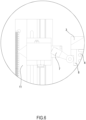
FIG 6 shows the detail ofFigure 5 in which the switching means is engaging the activating means. -
FIG 7 exemplarily shows the force/displacement diagrams of two real tyres and the apparatus respectively. - In
Figure 1 , thenumber 1 indicates in the entirety thereof, an apparatus for simulating a tyre behavior in a plunger test (also called a plunger test simulator tool). - The
apparatus 1 is provided with aground plate 2 that is firmly fixed to thetyre supporting hub 50 of the plunger test machine 100 (only schematically shown) throughfixing means 13. The fixing means 13 are preferably elongated bars passing below thetyre supporting hub 50 and being fastened to theground plate 2 preferably via screws, thereby fastening thetyre supporting hub 50 between theground plate 2 and the elongated bars. - To guarantee measurement precision it is important that the
ground plate 2 of theapparatus 1 is firmly fixed on thetyre supporting hub 50 of theplunger test machine 100 and that any movement of theground plate 2 is inhibited. - The
apparatus 1 further comprises a supportingplate 3 being movably connected to theground plate 2 bydamping means 4. - The damping means 4 extend from the upper surface of the
ground plate 2 to the lower surface of the supportingplate 3. - The upper surface of the
ground plate 2 and the lower surface of the supportingplate 3 are parallel to each other. - The supporting
plate 3 is supported by the damping means 4. - The damping means 4 preferably comprise at least a spring.
- The damping means 4 preferably comprise a plurality of springs.
- In addition to supporting the supporting
plate 3, the damping means 4 have the function of reproducing the vertical stiffness of a real tyre. - Specific calibration of the damping means 4 is required to reproduce real tyres of different sizes or, more in general, tyres of different categories (passenger vehicle tyres, commercial van tyres, truck tyres, etc.) as well as different inflation conditions.
- As can be seen in
Fig. 7 , during a plunger test the resulting displacement of theplunger 10 according to the force applied to the tyre are plotted. The average slope of the resulting graph is the vertical stiffness of a tyre and represents its spring constant k. - In
Fig. 7 the solid line represents the plunger test results with the apparatus for simulating a tyre behavior in a plunger test whereas the dashed line shows the result on a real tyre of the size 255/50 R20 having a resulting spring constant of about 10.5 kg/mm and the dotted one the result of a real tyre of the size 265/30 R21 having a resulting spring constant of about 7.5 kg/mm. Both tyres were inflated at 2.0 bar. The spring constant of the damping means 4 is about 8.9 kg/mm. - With calibration of the damping means 4 it is meant that the total spring constant of the damping means 4 should represent the range of spring constants of a particular tyre type.
- The table below shows possible ranges of spring constants of different tyre categories.
Table I Tyre category Range of spring constant [kg/mm] Passenger Vehicle Tyres 5 ~12 Commercial Van Tyres 13 ~ 22 Truck and Bus Tyres 30 ~ 50 - The damping means 4 should be calibrated and selected such that they can represent the vertical stiffness, i.e. the spring constant, of a category of tyres.
- It also possible to reproduce the exact spring constant of a specific tyre size and specification once this is known.
- In a preferred embodiment the damping means 4 consists of 12 single sprigs. Given the total spring constant kT of the damping means 4 of 8.9 kg/mm, each single spring has a spring constant kS of 0.74 kg/mm since in the embodiment shown in
figures 1 to 5 the springs of the damping means 4 have a parallel configuration. - The damping means 4 are arranged symmetrically over the upper surface of the
ground plate 2 and the lower surface of the supportingpate 3 in order to evenly distribute the load of the supporting plate as well as the load applied during the plunger test. - The symmetric distribution of the damping means 4 allows also that the upper surface of the
ground plate 2 and the lower surface of the supportingplate 3 remain parallel during the displacement of the supportingplate 2. - Preferably the
ground plate 2 and the supportingplate 3 are of rectangular shape and have the same dimensions, i.e. the upper surface of theground plate 2 and the lower surface of the supportingplate 3 have the same surface area. - Preferably the damping means 4 are distributed on two distal sides of the upper surface of the ground plate and the lower surface of the supporting plate respectively.
- The damping means 4 connecting the supporting
plate 3 to theground plate 2 preferably allow a displacement only along a preferred axis of translation. The preferred axis of translation being orthogonal to both the upper surface of theground plate 2 and the lower surface of the supportingplate 3. - To further assure the displacement of the supporting
plate 3 only along the preferred axis of translation, theapparatus 1 preferably comprises guiding means 9. - The guiding means 9 extend in the preferred axis of translation and are fixedly connected with the
ground plate 2. - The guiding means 9 are preferably rods or shafts, preferably with circular section.
- Preferably the
apparatus 1 comprises as many guiding means 9 as dampingmeans 4. - Preferably the guiding means 9 and the damping means 4 are respectively coaxial, i.e. every single element of the guiding means 9 is coaxial to a single element of the damping
means 4. - Preferably the guiding means 9 are located respectively axially inside the damping means 4, in other words each element of the damping means 4 surrounds an element of the guiding means 9.
- The supporting
plate 3 comprises at least one pass-through hole whose dimensions are such that the guiding means 9 can pass through it whereas the damping means 4 cannot. - The guiding means 9 comprise a limiting
element 14 at its distal end from theground plate 2. The limitingelement 14 is located at the end of the guiding means 9 that passes through the pass-through hole in the supportingplate 3. The limitingelement 14 is located on the opposite side of the supportingplate 3 than the dampingmeans 4. - The limiting
element 14 has firstly the function of securing the supportingplate 3 to the guiding means 9, or more precisely to secure that the supportingplate 3 would not move beyond the guiding means 9 and secondly of adjusting the initial compression of the dampingmeans 4. - With initial compression of the damping means 4 it is meant the compression of the springs when no force is applied to the
apparatus 1 via theplunger 10. - The limiting
element 14 preferably comprises a ring and a bolt. - The limiting
element 14 is preferably connected to the guiding means 9 via a thread. - The
apparatus 1 further comprises a pneumatic orhydraulic actuator 5 being firmly connected to the supportingplate 3. - The pneumatic or
hydraulic actuator 5 comprises anactuator piston 6. - The pneumatic or
hydraulic actuator 5 is preferably a pneumatic or hydraulic cylinder. - The pneumatic or
hydraulic actuator 5 is suitable for being filled with a compressed fluid when in operation; when filled with the compressed fluid the pneumatic orhydraulic actuator 5 prompts theactuator piston 6 to translate in an extended position, as can be seen infigure 3 . - Vice-versa when the compressed fluid is discharged from the pneumatic or
hydraulic actuator 5 theactuator piston 6 retracts in a retracted position, as can be seen infigures 1 or2 . - The translation axis T of the
actuator piston 6 is parallel to the preferred axis of translation. - The
apparatus 1 further comprises activating means 7 suitable to trigger the discharge of the pneumatic orhydraulic cylinder 5. - When the activating means 7 are engaged or activated, they prompt the the pneumatic or
hydraulic actuator 5 to discharge the compressed fluid, thereby simulating the breakage of the tyre. - The activating means 7 are preferably mechanical activating means 7, e.g. a lever, or optical activating means 7, e.g. a photocell.
- The activating means 7 are preferably connected to the
ground plate 2. - The
apparatus 1 may further comprise apositioning rod 11. The positioning rod is preferably connected to theground plate 2. - The activating means 7 are preferably connected to the
ground plate 2 through thepositioning rod 11. - The
positioning rod 11 is suitable for positioning the activating means 7 at different positions or heights along the preferred axis of translation T. - The
apparatus 1 further comprises switching means 8 suitable to engage the activating means 7 when the supportingplate 3 is being displaced. - The switching means 8 are preferably connected to the supporting
plate 3. - The positioning of the activating means 7 at different positions or heights allows to select the displacement of the supporting
plate 3 at which the switching means 8 will engage the activating means 7 and consequently theapparatus 1 will simulate the tyre breakage. - The
apparatus 1 may further comprise adisplacement gauge 16 for measuring the displacement between theground plate 2 and the supportingplate 3 during the plunger test. - The
apparatus 1 may further comprise a load cell 17 (not shown in the figures) positioned on the outer end of theactuator piston 6, between theactuator piston 6 and theplunger 10. - The load cell 17 is suitable for measuring the applied force on the
apparatus 1 simulating the behavior of a tyre during the plunger test. - The measurement of the applied force via the load cell 17 and the displacement between the
ground plate 2 and the supportingplate 3 will provide a way to calculate the energy required to break the tyre during the plunger test. - The measurement of force and displacement via the load cell 17 and the
displacement gauge 16 will provide comparative data in addition or in substitution of those measured by the plunger test machine itself. The additional comparative dataset can be used also to check the proper function of the plunger test machine. - In operation, the
apparatus 1 is mounted on thetyre supporting hub 50 of aplunger test machine 100; the pneumatic orhydraulic actuator 5 is filled with a compressed fluid, this prompts theactuator piston 6 to translate in its extended position. Before starting the plunger test, theplunger 10 of theplunger test machine 100 is pushed against theactuator piston 6 as can be seen inFigure 3 . - During the plunger test procedure a force is applied to the
plunger 10 of the machine that consequently displaces theactuator piston 6 and the pneumatic orhydraulic actuator 5 as can be seen inFigures 4 and5 . - Being the pneumatic or
hydraulic actuator 5 firmly connected to the supportingplate 3, the supportingplate 3 is pushed downwards, i.e. along the preferred axis of translation towards theground plate 2. - The damping means 4 are thereby compressed.
- At a predetermined height the switching means 8 positioned on the supporting
plate 3 will engage with the activating means 7 (as can be seen inFigures 5 and6 ) thereby triggering the discharge of the compressed fluid from the pneumatic orhydraulic actuator 5 and simulating the breakage of the tyre. - A method for simulating a tyre behavior during a plunger test is also provided by this invention.
- The method comprises using the
apparatus 1 instead of a real tyre during a plunger test. - The method comprising the steps of mounting the
apparatus 1 onto thetyre supporting hub 50 of aplunger test machine 100; filling the pneumatic orhydraulic actuator 5 with a compressed fluid, thereby prompting theactuator piston 6 to translate in its extended position; pushing theplunger 10 of theplunger test machine 100 against theactuator piston 6; starting the plunger test applying a force to theplunger 10; displacing the supportingplate 3 via the force applied to theactuator piston 6 until the switching means 8 will engage the activating means 7 thereby triggering the discharge of the compressed fluid from the pneumatic orhydraulic actuator 5 and simulating the breakage of the tyre. - The method may further comprise the steps of applying a load cell 17 between the
actuator piston 6 and theplunger 10; measuring the applied force and the displacement between theground plate 2 and the supportingplate 3 during the test; calculating the energy at which the simulation of the tyre breakage occurs. -
- 1
- apparatus
- 2
- ground plate
- 3
- supporting plate
- 4
- damping means
- 5
- pneumatic or hydraulic actuator
- 6
- actuator piston
- 7
- activating means
- 8
- switching means
- 9
- guiding means
- 10
- plunger
- 11
- positioning rod
- 13
- fixing means
- 14
- limiting element
- 15
- tyre supporting hub
- 16
- displacement gauge
- 17
- load cell
- 100
- plunger test machine
- T
- Preferred axis of translation
Claims (12)
- Apparatus for simulating a tyre behavior in a plunger test, comprising- a ground plate suitable for being firmly fixed to a tyre supporting hub of a plunger test machine,- a supporting plate being movably connected to the ground plate by damping means, wherein the damping means allow a displacement only along a preferred axis of translation,- a pneumatic or hydraulic actuator being connected to the supporting plate, wherein the pneumatic or hydraulic actuator is suitable for being filled with a compressed fluid when in operation and wherein the pneumatic or hydraulic actuator comprises an actuator piston,- activating means being connected to the ground plate and suitable to trigger the discharge of the compressed fluid in the pneumatic or hydraulic cylinder when activated,- switching means connected to the supporting plate suitable to engage the activating means when the supporting plate is being displaced, wherein the supporting plate is suitable to being moved along the preferred axis of translation when a force is applied to the actuator piston.
- Apparatus according to claim 1 further comprising a positioning rod connected to the ground plate wherein the activating means are connected to the ground plate through the positioning rod, and wherein the positioning rod is suitable for positioning the activating means at different positions along the preferred axis of translation.
- Apparatus according to any preceding claim wherein the damping means comprise at least a spring.
- Apparatus according to any preceding claim wherein the damping means are symmetrically distributed over the surface of the ground plate and the supporting plate.
- Apparatus of claim 4 wherein the damping means are distributed on two distal sides of the surface of the ground plate and the supporting plate respectively.
- Apparatus according to any preceding claim wherein the pneumatic or hydraulic actuator is a pneumatic cylinder.
- Apparatus according to any preceding claim wherein the apparatus further comprises a displacement gauge for measuring the displacement of the supporting plate with respect to the ground plate.
- Apparatus according to any preceding claim wherein the apparatus further comprises a load cell connected to the actuator piston for measuring the applied force on the actuator piston.
- Apparatus according to any of previous claims wherein the damping means have a spring constants in one of the ranges 5 to12 kg/mm, 13 to 22 kg/mm or 30 to 50 kg/mm.
- Method for performing a plunger test on a plunger test machine using the apparatus of any preceding claims comprising the steps of:- fixing the apparatus to a supporting hub of the plunger test machine,- filling the pneumatic or hydraulic actuator with a fluid, wherein the actuator rod is thereby lifted towards a plunger of the plunger test machine,- starting the plunger test by applying trough the plunger a force onto the actuator piston causing the supporting plate to displace along a preferred axle of translation,- ending the test when the switching means engage the activating means due to the displacement of the supporting plate.
- Method of claim 10 further comprising the steps of:- measuring the displacement of the supporting plate via a displacement gauge,- measuring the force applied to the plunger via the load cell and- calculating the energy at which the simulation of tyre breakage occurs.
- Method of claim 11 further comprising the step of selecting the damping means within one of the group of damping means having spring constants in the ranges 5 to 12 kg/mm, 13 to 22 kg/mm or 30 to 50 kg/mm.
Priority Applications (3)
| Application Number | Priority Date | Filing Date | Title |
|---|---|---|---|
| EP22181254.8A EP4300067B1 (en) | 2022-06-27 | 2022-06-27 | Apparatus and method for simulating the tyre behavior in a plunger test |
| JP2024576732A JP7872863B2 (en) | 2022-06-27 | 2023-06-23 | Apparatus and method for simulating tire behavior in plunger testing |
| PCT/EP2023/067203 WO2024002911A1 (en) | 2022-06-27 | 2023-06-23 | Apparatus and method for simulating the tyre behavior in a plunger test |
Applications Claiming Priority (1)
| Application Number | Priority Date | Filing Date | Title |
|---|---|---|---|
| EP22181254.8A EP4300067B1 (en) | 2022-06-27 | 2022-06-27 | Apparatus and method for simulating the tyre behavior in a plunger test |
Publications (2)
| Publication Number | Publication Date |
|---|---|
| EP4300067A1 true EP4300067A1 (en) | 2024-01-03 |
| EP4300067B1 EP4300067B1 (en) | 2025-04-16 |
Family
ID=82321353
Family Applications (1)
| Application Number | Title | Priority Date | Filing Date |
|---|---|---|---|
| EP22181254.8A Active EP4300067B1 (en) | 2022-06-27 | 2022-06-27 | Apparatus and method for simulating the tyre behavior in a plunger test |
Country Status (3)
| Country | Link |
|---|---|
| EP (1) | EP4300067B1 (en) |
| JP (1) | JP7872863B2 (en) |
| WO (1) | WO2024002911A1 (en) |
Citations (1)
| Publication number | Priority date | Publication date | Assignee | Title |
|---|---|---|---|---|
| KR20120092965A (en) * | 2011-02-14 | 2012-08-22 | 주식회사 대화산기 | Tire plunger and bead unseat test machine |
Family Cites Families (5)
| Publication number | Priority date | Publication date | Assignee | Title |
|---|---|---|---|---|
| US3662597A (en) | 1970-06-25 | 1972-05-16 | Getty Machine And Mold Inc | Tire testing machine |
| US4348891A (en) * | 1981-02-04 | 1982-09-14 | The B F Goodrich Company | Tire hardness tester |
| JPH07140048A (en) * | 1993-11-18 | 1995-06-02 | Sumitomo Rubber Ind Ltd | Tire loading device |
| US7461556B2 (en) | 2005-11-03 | 2008-12-09 | Chip Ganassi Racing Teams, Inc. | Test system for dynamically analyzing a vehicle under simulated road conditions |
| US12216023B2 (en) | 2022-09-12 | 2025-02-04 | Ektron Tek Co., Ltd. | Testing machine for tires |
-
2022
- 2022-06-27 EP EP22181254.8A patent/EP4300067B1/en active Active
-
2023
- 2023-06-23 WO PCT/EP2023/067203 patent/WO2024002911A1/en not_active Ceased
- 2023-06-23 JP JP2024576732A patent/JP7872863B2/en active Active
Patent Citations (1)
| Publication number | Priority date | Publication date | Assignee | Title |
|---|---|---|---|---|
| KR20120092965A (en) * | 2011-02-14 | 2012-08-22 | 주식회사 대화산기 | Tire plunger and bead unseat test machine |
Also Published As
| Publication number | Publication date |
|---|---|
| WO2024002911A1 (en) | 2024-01-04 |
| EP4300067B1 (en) | 2025-04-16 |
| JP2025520831A (en) | 2025-07-03 |
| JP7872863B2 (en) | 2026-06-10 |
Similar Documents
| Publication | Publication Date | Title |
|---|---|---|
| US7530264B2 (en) | Test apparatus for accelerated wheel and suspension component structural durability | |
| DE3545087C2 (en) | ||
| KR102182929B1 (en) | Tire rolling resistance evaluation device | |
| KR101850877B1 (en) | Drop impact test equipment | |
| CN111912704A (en) | New energy automobile tire static test system and test method | |
| EP4300067B1 (en) | Apparatus and method for simulating the tyre behavior in a plunger test | |
| CN102466570A (en) | Pedestrian protection leg impact test device and using method thereof | |
| CN219715019U (en) | Tire burst test tool | |
| EP2161235B1 (en) | Lifting device, particularly for lifting wheels of vehicles and the like, for wheel balancing and tire removing machines | |
| WO2019049304A1 (en) | Impact test device | |
| US3662597A (en) | Tire testing machine | |
| US5127271A (en) | Method of non-destructive inspection for resinous automotive bumper beams | |
| CN111846277B (en) | Aircraft landing gear equipped with a device for detecting bottoming out of its shock absorber | |
| KR20120092965A (en) | Tire plunger and bead unseat test machine | |
| CN112945584A (en) | Tire impact resistance testing device | |
| KR101510184B1 (en) | Impact tester of car-door and computer-readable recording medium having impact testing program | |
| CN108507660B (en) | A load cell verification method for a flat-plate brake inspection platform | |
| US20040163455A1 (en) | Tire testing machine and process | |
| CN118641223A (en) | A strength detection system for automobile anti-collision protection device | |
| CN217331894U (en) | Wood compression test tool | |
| CN213779511U (en) | Electric automobile drags end test bench | |
| CN211954413U (en) | Weighing sensor calibrating device of flat brake inspection platform | |
| CN204694438U (en) | A kind of baggage carrier of vehicle durability test device | |
| US3715720A (en) | Apparatus for deteamining an underinflated condition in pneumatic tires | |
| CN113790194A (en) | Dumper lifting hydraulic cylinder simulation working condition test device |
Legal Events
| Date | Code | Title | Description |
|---|---|---|---|
| PUAI | Public reference made under article 153(3) epc to a published international application that has entered the european phase |
Free format text: ORIGINAL CODE: 0009012 |
|
| STAA | Information on the status of an ep patent application or granted ep patent |
Free format text: STATUS: THE APPLICATION HAS BEEN PUBLISHED |
|
| AK | Designated contracting states |
Kind code of ref document: A1 Designated state(s): AL AT BE BG CH CY CZ DE DK EE ES FI FR GB GR HR HU IE IS IT LI LT LU LV MC MK MT NL NO PL PT RO RS SE SI SK SM TR |
|
| STAA | Information on the status of an ep patent application or granted ep patent |
Free format text: STATUS: REQUEST FOR EXAMINATION WAS MADE |
|
| 17P | Request for examination filed |
Effective date: 20240702 |
|
| RBV | Designated contracting states (corrected) |
Designated state(s): AL AT BE BG CH CY CZ DE DK EE ES FI FR GB GR HR HU IE IS IT LI LT LU LV MC MK MT NL NO PL PT RO RS SE SI SK SM TR |
|
| GRAP | Despatch of communication of intention to grant a patent |
Free format text: ORIGINAL CODE: EPIDOSNIGR1 |
|
| STAA | Information on the status of an ep patent application or granted ep patent |
Free format text: STATUS: GRANT OF PATENT IS INTENDED |
|
| INTG | Intention to grant announced |
Effective date: 20240829 |
|
| GRAS | Grant fee paid |
Free format text: ORIGINAL CODE: EPIDOSNIGR3 |
|
| GRAA | (expected) grant |
Free format text: ORIGINAL CODE: 0009210 |
|
| STAA | Information on the status of an ep patent application or granted ep patent |
Free format text: STATUS: THE PATENT HAS BEEN GRANTED |
|
| AK | Designated contracting states |
Kind code of ref document: B1 Designated state(s): AL AT BE BG CH CY CZ DE DK EE ES FI FR GB GR HR HU IE IS IT LI LT LU LV MC MK MT NL NO PL PT RO RS SE SI SK SM TR |
|
| REG | Reference to a national code |
Ref country code: GB Ref legal event code: FG4D |
|
| REG | Reference to a national code |
Ref country code: CH Ref legal event code: EP |
|
| REG | Reference to a national code |
Ref country code: IE Ref legal event code: FG4D |
|
| REG | Reference to a national code |
Ref country code: DE Ref legal event code: R096 Ref document number: 602022013139 Country of ref document: DE |
|
| P01 | Opt-out of the competence of the unified patent court (upc) registered |
Free format text: CASE NUMBER: APP_21618/2025 Effective date: 20250507 |
|
| PGFP | Annual fee paid to national office [announced via postgrant information from national office to epo] |
Ref country code: AT Payment date: 20250721 Year of fee payment: 4 |
|
| REG | Reference to a national code |
Ref country code: NL Ref legal event code: MP Effective date: 20250416 |
|
| PG25 | Lapsed in a contracting state [announced via postgrant information from national office to epo] |
Ref country code: NL Free format text: LAPSE BECAUSE OF FAILURE TO SUBMIT A TRANSLATION OF THE DESCRIPTION OR TO PAY THE FEE WITHIN THE PRESCRIBED TIME-LIMIT Effective date: 20250416 |
|
| REG | Reference to a national code |
Ref country code: AT Ref legal event code: MK05 Ref document number: 1785994 Country of ref document: AT Kind code of ref document: T Effective date: 20250416 |
|
| PG25 | Lapsed in a contracting state [announced via postgrant information from national office to epo] |
Ref country code: FI Free format text: LAPSE BECAUSE OF FAILURE TO SUBMIT A TRANSLATION OF THE DESCRIPTION OR TO PAY THE FEE WITHIN THE PRESCRIBED TIME-LIMIT Effective date: 20250416 Ref country code: ES Free format text: LAPSE BECAUSE OF FAILURE TO SUBMIT A TRANSLATION OF THE DESCRIPTION OR TO PAY THE FEE WITHIN THE PRESCRIBED TIME-LIMIT Effective date: 20250416 Ref country code: PT Free format text: LAPSE BECAUSE OF FAILURE TO SUBMIT A TRANSLATION OF THE DESCRIPTION OR TO PAY THE FEE WITHIN THE PRESCRIBED TIME-LIMIT Effective date: 20250818 |
|
| REG | Reference to a national code |
Ref country code: LT Ref legal event code: MG9D |
|
| PG25 | Lapsed in a contracting state [announced via postgrant information from national office to epo] |
Ref country code: NO Free format text: LAPSE BECAUSE OF FAILURE TO SUBMIT A TRANSLATION OF THE DESCRIPTION OR TO PAY THE FEE WITHIN THE PRESCRIBED TIME-LIMIT Effective date: 20250716 Ref country code: GR Free format text: LAPSE BECAUSE OF FAILURE TO SUBMIT A TRANSLATION OF THE DESCRIPTION OR TO PAY THE FEE WITHIN THE PRESCRIBED TIME-LIMIT Effective date: 20250717 |
|
| PG25 | Lapsed in a contracting state [announced via postgrant information from national office to epo] |
Ref country code: PL Free format text: LAPSE BECAUSE OF FAILURE TO SUBMIT A TRANSLATION OF THE DESCRIPTION OR TO PAY THE FEE WITHIN THE PRESCRIBED TIME-LIMIT Effective date: 20250416 |
|
| PG25 | Lapsed in a contracting state [announced via postgrant information from national office to epo] |
Ref country code: BG Free format text: LAPSE BECAUSE OF FAILURE TO SUBMIT A TRANSLATION OF THE DESCRIPTION OR TO PAY THE FEE WITHIN THE PRESCRIBED TIME-LIMIT Effective date: 20250416 |
|
| PG25 | Lapsed in a contracting state [announced via postgrant information from national office to epo] |
Ref country code: HR Free format text: LAPSE BECAUSE OF FAILURE TO SUBMIT A TRANSLATION OF THE DESCRIPTION OR TO PAY THE FEE WITHIN THE PRESCRIBED TIME-LIMIT Effective date: 20250416 Ref country code: AT Free format text: LAPSE BECAUSE OF FAILURE TO SUBMIT A TRANSLATION OF THE DESCRIPTION OR TO PAY THE FEE WITHIN THE PRESCRIBED TIME-LIMIT Effective date: 20250416 |
|
| PG25 | Lapsed in a contracting state [announced via postgrant information from national office to epo] |
Ref country code: RS Free format text: LAPSE BECAUSE OF FAILURE TO SUBMIT A TRANSLATION OF THE DESCRIPTION OR TO PAY THE FEE WITHIN THE PRESCRIBED TIME-LIMIT Effective date: 20250716 |
|
| PG25 | Lapsed in a contracting state [announced via postgrant information from national office to epo] |
Ref country code: IS Free format text: LAPSE BECAUSE OF FAILURE TO SUBMIT A TRANSLATION OF THE DESCRIPTION OR TO PAY THE FEE WITHIN THE PRESCRIBED TIME-LIMIT Effective date: 20250816 |
|
| PG25 | Lapsed in a contracting state [announced via postgrant information from national office to epo] |
Ref country code: LV Free format text: LAPSE BECAUSE OF FAILURE TO SUBMIT A TRANSLATION OF THE DESCRIPTION OR TO PAY THE FEE WITHIN THE PRESCRIBED TIME-LIMIT Effective date: 20250416 |
|
| PG25 | Lapsed in a contracting state [announced via postgrant information from national office to epo] |
Ref country code: DK Free format text: LAPSE BECAUSE OF FAILURE TO SUBMIT A TRANSLATION OF THE DESCRIPTION OR TO PAY THE FEE WITHIN THE PRESCRIBED TIME-LIMIT Effective date: 20250416 Ref country code: SM Free format text: LAPSE BECAUSE OF FAILURE TO SUBMIT A TRANSLATION OF THE DESCRIPTION OR TO PAY THE FEE WITHIN THE PRESCRIBED TIME-LIMIT Effective date: 20250416 |
|
| REG | Reference to a national code |
Ref country code: DE Ref legal event code: R097 Ref document number: 602022013139 Country of ref document: DE |
|
| PG25 | Lapsed in a contracting state [announced via postgrant information from national office to epo] |
Ref country code: CZ Free format text: LAPSE BECAUSE OF FAILURE TO SUBMIT A TRANSLATION OF THE DESCRIPTION OR TO PAY THE FEE WITHIN THE PRESCRIBED TIME-LIMIT Effective date: 20250416 |
|
| PG25 | Lapsed in a contracting state [announced via postgrant information from national office to epo] |
Ref country code: EE Free format text: LAPSE BECAUSE OF FAILURE TO SUBMIT A TRANSLATION OF THE DESCRIPTION OR TO PAY THE FEE WITHIN THE PRESCRIBED TIME-LIMIT Effective date: 20250416 |
|
| PG25 | Lapsed in a contracting state [announced via postgrant information from national office to epo] |
Ref country code: SK Free format text: LAPSE BECAUSE OF FAILURE TO SUBMIT A TRANSLATION OF THE DESCRIPTION OR TO PAY THE FEE WITHIN THE PRESCRIBED TIME-LIMIT Effective date: 20250416 |
|
| REG | Reference to a national code |
Ref country code: CH Ref legal event code: H13 Free format text: ST27 STATUS EVENT CODE: U-0-0-H10-H13 (AS PROVIDED BY THE NATIONAL OFFICE) Effective date: 20260127 |
|
| PG25 | Lapsed in a contracting state [announced via postgrant information from national office to epo] |
Ref country code: MC Free format text: LAPSE BECAUSE OF FAILURE TO SUBMIT A TRANSLATION OF THE DESCRIPTION OR TO PAY THE FEE WITHIN THE PRESCRIBED TIME-LIMIT Effective date: 20250416 |
|
| PG25 | Lapsed in a contracting state [announced via postgrant information from national office to epo] |
Ref country code: LU Free format text: LAPSE BECAUSE OF NON-PAYMENT OF DUE FEES Effective date: 20250627 |
|
| PLBE | No opposition filed within time limit |
Free format text: ORIGINAL CODE: 0009261 |
|
| STAA | Information on the status of an ep patent application or granted ep patent |
Free format text: STATUS: NO OPPOSITION FILED WITHIN TIME LIMIT |
|
| REG | Reference to a national code |
Ref country code: CH Ref legal event code: L10 Free format text: ST27 STATUS EVENT CODE: U-0-0-L10-L00 (AS PROVIDED BY THE NATIONAL OFFICE) Effective date: 20260225 |
|
| REG | Reference to a national code |
Ref country code: BE Ref legal event code: MM Effective date: 20250630 |
|
| PG25 | Lapsed in a contracting state [announced via postgrant information from national office to epo] |
Ref country code: RO Free format text: LAPSE BECAUSE OF FAILURE TO SUBMIT A TRANSLATION OF THE DESCRIPTION OR TO PAY THE FEE WITHIN THE PRESCRIBED TIME-LIMIT Effective date: 20250416 |
|
| 26N | No opposition filed |
Effective date: 20260119 |
|
| PG25 | Lapsed in a contracting state [announced via postgrant information from national office to epo] |
Ref country code: IE Free format text: LAPSE BECAUSE OF NON-PAYMENT OF DUE FEES Effective date: 20250627 |
|
| PG25 | Lapsed in a contracting state [announced via postgrant information from national office to epo] |
Ref country code: BE Free format text: LAPSE BECAUSE OF NON-PAYMENT OF DUE FEES Effective date: 20250630 |
|
| PG25 | Lapsed in a contracting state [announced via postgrant information from national office to epo] |
Ref country code: CH Free format text: LAPSE BECAUSE OF NON-PAYMENT OF DUE FEES Effective date: 20250630 |
|
| PG25 | Lapsed in a contracting state [announced via postgrant information from national office to epo] |
Ref country code: LT Free format text: LAPSE BECAUSE OF FAILURE TO SUBMIT A TRANSLATION OF THE DESCRIPTION OR TO PAY THE FEE WITHIN THE PRESCRIBED TIME-LIMIT Effective date: 20250416 |
|
| PGFP | Annual fee paid to national office [announced via postgrant information from national office to epo] |
Ref country code: IT Payment date: 20260520 Year of fee payment: 5 |
|
| PGFP | Annual fee paid to national office [announced via postgrant information from national office to epo] |
Ref country code: DE Payment date: 20260520 Year of fee payment: 5 |
|
| PGFP | Annual fee paid to national office [announced via postgrant information from national office to epo] |
Ref country code: FR Payment date: 20260520 Year of fee payment: 5 |
|
| PG25 | Lapsed in a contracting state [announced via postgrant information from national office to epo] |
Ref country code: CY Free format text: LAPSE BECAUSE OF FAILURE TO SUBMIT A TRANSLATION OF THE DESCRIPTION OR TO PAY THE FEE WITHIN THE PRESCRIBED TIME-LIMIT Effective date: 20250416 Ref country code: SE Free format text: LAPSE BECAUSE OF FAILURE TO SUBMIT A TRANSLATION OF THE DESCRIPTION OR TO PAY THE FEE WITHIN THE PRESCRIBED TIME-LIMIT Effective date: 20250416 |