EP4299988A1 - Cooker - Google Patents
Cooker Download PDFInfo
- Publication number
- EP4299988A1 EP4299988A1 EP22759576.6A EP22759576A EP4299988A1 EP 4299988 A1 EP4299988 A1 EP 4299988A1 EP 22759576 A EP22759576 A EP 22759576A EP 4299988 A1 EP4299988 A1 EP 4299988A1
- Authority
- EP
- European Patent Office
- Prior art keywords
- wall
- heating cooking
- light source
- cooking chamber
- source unit
- Prior art date
- Legal status (The legal status is an assumption and is not a legal conclusion. Google has not performed a legal analysis and makes no representation as to the accuracy of the status listed.)
- Pending
Links
- 238000010438 heat treatment Methods 0.000 claims abstract description 164
- 238000010411 cooking Methods 0.000 claims abstract description 147
- 239000002184 metal Substances 0.000 claims description 48
- 238000004891 communication Methods 0.000 claims description 22
- 239000000758 substrate Substances 0.000 claims description 19
- 239000011521 glass Substances 0.000 claims description 12
- 239000000463 material Substances 0.000 description 8
- 230000002093 peripheral effect Effects 0.000 description 4
- 230000004308 accommodation Effects 0.000 description 3
- 239000000470 constituent Substances 0.000 description 3
- 238000010586 diagram Methods 0.000 description 3
- 238000012856 packing Methods 0.000 description 3
- 230000000694 effects Effects 0.000 description 2
- 238000012546 transfer Methods 0.000 description 2
- 239000000919 ceramic Substances 0.000 description 1
- 239000004973 liquid crystal related substance Substances 0.000 description 1
- 238000000034 method Methods 0.000 description 1
- 238000012986 modification Methods 0.000 description 1
- 230000004048 modification Effects 0.000 description 1
- 229910052755 nonmetal Inorganic materials 0.000 description 1
- 229920003002 synthetic resin Polymers 0.000 description 1
- 239000000057 synthetic resin Substances 0.000 description 1
Images





Classifications
-
- F—MECHANICAL ENGINEERING; LIGHTING; HEATING; WEAPONS; BLASTING
- F24—HEATING; RANGES; VENTILATING
- F24C—DOMESTIC STOVES OR RANGES ; DETAILS OF DOMESTIC STOVES OR RANGES, OF GENERAL APPLICATION
- F24C15/00—Details
- F24C15/008—Illumination for oven cavities
-
- H—ELECTRICITY
- H05—ELECTRIC TECHNIQUES NOT OTHERWISE PROVIDED FOR
- H05B—ELECTRIC HEATING; ELECTRIC LIGHT SOURCES NOT OTHERWISE PROVIDED FOR; CIRCUIT ARRANGEMENTS FOR ELECTRIC LIGHT SOURCES, IN GENERAL
- H05B6/00—Heating by electric, magnetic or electromagnetic fields
- H05B6/64—Heating using microwaves
- H05B6/6444—Aspects relating to lighting devices in the microwave cavity
-
- H—ELECTRICITY
- H05—ELECTRIC TECHNIQUES NOT OTHERWISE PROVIDED FOR
- H05B—ELECTRIC HEATING; ELECTRIC LIGHT SOURCES NOT OTHERWISE PROVIDED FOR; CIRCUIT ARRANGEMENTS FOR ELECTRIC LIGHT SOURCES, IN GENERAL
- H05B6/00—Heating by electric, magnetic or electromagnetic fields
- H05B6/64—Heating using microwaves
- H05B6/6414—Aspects relating to the door of the microwave heating apparatus
-
- F—MECHANICAL ENGINEERING; LIGHTING; HEATING; WEAPONS; BLASTING
- F24—HEATING; RANGES; VENTILATING
- F24C—DOMESTIC STOVES OR RANGES ; DETAILS OF DOMESTIC STOVES OR RANGES, OF GENERAL APPLICATION
- F24C15/00—Details
- F24C15/16—Shelves, racks or trays inside ovens; Supports therefor
- F24C15/162—Co-operating with a door, e.g. operated by the door
Definitions
- the present invention relates to a heating cooking apparatus.
- PTL 1 discloses a heating cooking device.
- the heating cooking device disclosed in PTL 1 includes a heating chamber and a light source.
- the heating chamber accommodates an object to be heated.
- the light source is disposed on a ceiling portion of the heating chamber. The light source emits light in the heating chamber.
- the light source emits light in a direction orthogonal to the ceiling.
- a heating cooking chamber such as a heating chamber or an object to be heated that is accommodated in the heating cooking chamber cannot be observed in detail from an opening portion side of the heating cooking device.
- an object of the present invention is to provide a heating cooking apparatus that allows detailed observation of the inside of a heating cooking chamber or an object to be heated that is accommodated in the heating cooking chamber.
- a heating cooking apparatus includes a heating cooking chamber, a first recessed portion, and a first light source unit.
- the heating cooking chamber includes an opening portion opening in a predetermined direction, a back wall disposed in a direction opposite to the predetermined direction with respect to the opening portion, and a plurality of walls extending from the back wall in the predetermined direction.
- the first recessed portion is located in a first wall of the plurality of walls and recessed from the first wall.
- the first recessed portion includes a first inclined wall inclined with respect to the first wall.
- the first light source unit is disposed on the first inclined wall. The first light source unit emits light toward the back wall of the heating cooking chamber.
- the heating cooking apparatus of the present invention allows detailed observation of the inside of the heating cooking chamber or an object to be heated that is accommodated in the heating cooking chamber.
- FIG. 1 is a perspective view illustrating the pull-out type heating cooking apparatus 100.
- FIG. 2 is a right side view illustrating the pull-out type heating cooking apparatus 100.
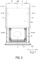
- FIG. 3 is a top view illustrating the pull-out type heating cooking apparatus 100. More specifically, FIG. 1 to FIG. 3 illustrate the pull-out type heating cooking apparatus 100 in a state where a pull-out body 2 is pulled out. Further, FIG. 1 illustrates an external appearance of the pull-out type heating cooking apparatus 100 as viewed diagonally from the upper front right.
- the pull-out type heating cooking apparatus 100 is an example of "heating cooking apparatus".
- the pull-out type heating cooking apparatus 100 heats and cooks an object H to be heated.
- the object H to be heated is, for example, a foodstuff.
- the pull-out type heating cooking apparatus 100 includes a heating chamber 1, the pull-out body 2, an operation panel 3, and a heating cooking chamber 100A.
- a side on which the operation panel 3 of the pull-out type heating cooking apparatus 100 is disposed is defined as a front side of the pull-out type heating cooking apparatus 100, and a side opposite to the front side (rear face side) is defined as a rear side of the pull-out type heating cooking apparatus 100.
- a right side when the pull-out type heating cooking apparatus 100 is viewed from the front side is defined as a right side of the pull-out type heating cooking apparatus 100
- a side opposite to the right side is defined as a left side of the pull-out type heating cooking apparatus 100.
- a side on which the operation panel 3 is disposed is defined as an upper side of the pull-out type heating cooking apparatus 100, and a side opposite to the upper side (bottom side) is defined as a lower side of the pull-out type heating cooking apparatus 100. Note that these orientations do not limit an orientation of the pull-out type heating cooking apparatus 100 in use.
- the heating chamber 1 is a box-like member. Specifically, the heating chamber 1 includes a right outer wall 1G, a left outer wall 1H, a top outer wall 1J, a bottom outer wall 1F, and a back outer wall 1K. The heating chamber 1 accommodates the heating cooking chamber 100A.
- the pull-out body 2, on which the object H to be heated is placed, can be pulled out in a first direction D 1 from the heating cooking chamber 100A.
- the first direction D1 is an example of "predetermined direction”.
- the first direction D1 is the forward direction.
- a third direction D3 intersects the first direction D1.
- the third direction D3 is orthogonal to the first direction D1.
- the third direction D3 is an upward direction (direction opposite to a vertical direction).
- the pull-out body 2 includes a lid portion 21, a placing portion 22, and a support portion 23.
- the heating cooking chamber 100A includes an accommodation space 120 that accommodates the object H to be heated.
- the shape of the heating cooking chamber 100A is, for example, a substantially rectangular parallelepiped shape.
- the heating cooking chamber 100A includes a pair of side wall portions 10, a back wall 1E, and an opening portion 100B.
- the pair of side wall portions 10 correspond to an example of "a plurality of walls".
- the opening portion 100B opens in the first direction D1.
- the opening portion 100B communicates with the outside of the heating cooking chamber 100A.
- the back wall 1E is disposed in a direction opposite to the first direction D1 with respect to the opening portion 100B. That is, the opening portion 100B faces the back wall 1E.
- the pair of side wall portions 10 extend from the back wall 1E in the first direction D1. Moreover, the pair of side wall portions 10 face each other in a second direction D2.
- the second direction D2 is the left direction.
- the pair of side wall portions 10 include a right wall 1A and a left wall 1B.
- the right wall 1A corresponds to an example of "first wall”.
- the left wall 1B corresponds to an example of "second wall”.
- the heating cooking chamber 100A further includes a top wall 1C and a bottom wall 1D. Materials of the right wall 1A, the left wall 1B, the top wall 1C, the bottom wall 1D, and the back wall 1E are, for example, a metal.
- the heating chamber 1 further includes a space R between the heating chamber 1 and the heating cooking chamber 100A. Specifically, the heating chamber 1 further includes the space R between the bottom wall 1D and the bottom outer wall 1F. The heating chamber 1 further includes the space R between the right wall 1A and the right outer wall 1G. The heating chamber 1 further includes the space R between the left wall 1B and the left outer wall 1H. The heating chamber 1 further includes the space R between the top wall 1C and the top outer wall 1J. The heating chamber 1 further includes the space R between the back wall 1E and the back outer wall 1K.
- the pull-out type heating cooking apparatus 100 further includes a pair of rail members 11.
- one rail member of the pair of rail members 11 includes a right side rail member 111
- the other rail member of the pair of rail members 11 includes a left side rail member 112.
- the right side rail member 111 and the left side rail member 112 face each other in the second direction D2.
- Each of the right side rail member 111 and the left side rail member 112 is disposed in the heating chamber 1. Specifically, each of the right side rail member 111 and the left side rail member 112 is disposed between the heating chamber 1 and the heating cooking chamber 100A. More specifically, the right side rail member 111 is fixed to the right wall 1A in the space R between the right wall 1A and the right outer wall 1G. The left side rail member 112 is fixed to the left wall 1B in the space R between the left wall 1B and the left outer wall 1H. In particular, each of the right side rail member 111 and the left side rail member 112 extends in the first direction D1.
- the pull-out type heating cooking apparatus 100 further includes a pair of slide members 24.
- one slide member of the pair of slide members 24 includes a right side slide member 241
- the other slide member of the pair of slide members 24 includes a left side slide member 242.
- the right side slide member 241 and the left side slide member 242 face each other in the second direction D2.
- Each of the right side slide member 241 and the left side slide member 242 is disposed on the lid portion 21. Specifically, one end portion of the right side slide member 241 is attached to a right edge portion of the lid portion 21. One end portion of the left side slide member 242 is attached to a left edge portion of the lid portion 21. In particular, each of the right side slide member 241 and the left side slide member 242 extends in a direction opposite to the first direction D1 from the lid portion 21.
- the right side slide member 241 is slidably supported by the right side rail member 111.
- the left side slide member 242 is slidably supported by the left side rail member 112.
- the pull-out type heating cooking apparatus 100 further includes a support member 25.
- the support member 25 supports the lid portion 21.
- One end portion of the support member 25 is attached at a center portion of the lid portion 2 1 in the left-right direction and below the placing portion 22.
- the support member 25 is a plate-like member extending in the direction opposite to the first direction D1 from the lid portion 21.
- the support member 25 includes a rack portion.
- the rack portion includes teeth.
- the support member 25 may be a single plate-like member or a plurality of plate-like members.
- the pull-out type heating cooking apparatus 100 further includes a drive mechanism 4.
- the drive mechanism 4 drives the support member 25.
- the drive mechanism 4 is positioned below the heating cooking chamber 100A.
- the drive mechanism 4 is accommodated in the space R between the bottom wall 1D and the bottom outer wall 1F.
- the drive mechanism 4 includes a drive motor 41, a pinion, and a drive rail 42.
- the drive rail 42 is fixed in the space R between the bottom wall 1D and the bottom outer wall 1F.
- the drive rail 42 is a member whose longitudinal direction is the first direction D1.
- the support member 25 is slidably supported by the drive rail 42.
- the drive motor 41 rotates the pinion.
- the pinion engages with the rack portion of the support member 25. Furthermore, the support member 25 moves in the first direction D1 as a result of rotation of the pinion.
- the drive mechanism 4 may drive at least one of the support member 25, and the right side slide member 241 and the left side slide member 242. Furthermore, in a case where the right side slide member 241 and the left side slide member 242 are driven, the drive mechanism 4 may be positioned more on the side than the heating cooking chamber 100A.
- the operation panel 3 receives an operation from a user.
- the operation includes, for example, a cooking method for heating and cooking the object H to be heated, or information about movement of the lid portion 21 between the closed position and the open position thereof.
- the operation panel 3 includes a display unit, a storage unit, and a control unit.
- the display unit displays various pieces of information.
- the display unit includes a liquid crystal panel.
- the pull-out type heating cooking apparatus 100 further includes a first air sending unit 14, a second air sending unit 13, a grill unit 16, and a microwave supply unit 15.
- the first air sending unit 14 circulates air between the inside of the heating cooking chamber 100A and the first air sending unit 14.
- the second air sending unit 13 circulates air between the inside of the heating cooking chamber 100A and the second air sending unit 13.
- the grill unit 16 heats and cooks the obj ect H to be heated by conducting heat generated by a heater to the object H to be heated.
- the microwave supply unit 15 supplies microwaves into the heating cooking chamber 100A.
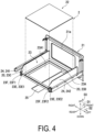
- FIG. 4 is an exploded perspective view illustrating the pull-out body 2 according to the present embodiment.
- the object H to be heated can be placed on the placing portion 22.
- the placing portion 22 includes a placing surface on which the object H to be heated is placed.
- the material of the placing portion 22 is a non-metal, and is preferably ceramic or glass, for example.
- the support portion 23 is attached to the lid portion 21 and supports a peripheral edge portion of the placing portion 22 such that the placing portion 22 is held in a horizontal state.
- the support portion 23 includes a bottom plate portion 23A and a pair of wall portions 20.
- the material of the support portion 23 is, for example, a metal.
- the bottom plate portion 23A includes a rectangular opening portion 23A1.
- the rectangular opening portion 23A1 is located at substantially a center portion of the bottom plate portion 23A.
- One wall portion of the pair of wall portions 20 includes a right side plate portion 23C, and the other wall portion of the pair of wall portions 20 includes a left side plate portion 23D.
- Each of the right side plate portion 23C and the left side plate portion 23D extends in substantially the first direction D1.
- the right side plate portion 23C and the left side plate portion 23D face each other in substantially the second direction D2. More specifically, the right side plate portion 23C and the left side plate portion 23D extend upward from the peripheral edge portion of the bottom plate portion 23A.
- the placing portion 22 is fitted among the lid portion 21, the right side plate portion 23C, and the left side plate portion 23D.
- the peripheral edge portion of the placing portion 22 is fixed to an upper surface of the peripheral edge portion of the bottom plate portion 23A.
- the support portion 23 further includes a pair of rollers 23E and a pair of rollers 23F.
- the pair of rollers 23E and the pair of rollers 23F rotate as the pull-out body 2 moves.
- one roller of the pair of rollers 23E includes a right side roller 23E1
- the other roller of the pair of rollers 23E includes a left side roller 23E2.
- the right side roller 23E1 and the left side roller 23E2 rotate about a rotation axis along substantially the second direction D2.
- the right side roller 23E1 is attached to a rear end portion of the right side plate portion 23C (on a side in a direction opposite to substantially the first direction D1).
- the left side roller 23E2 is attached to a rear end portion of the left side plate portion 23D.
- the right side roller 23E1 and the left side roller 23E2 are in contact with the bottom wall 1D.
- one roller of the pair of rollers 23F includes a right side roller 23F1
- the other roller of the pair of rollers 23F includes a left side roller 23F2.
- the right side roller 23F1 and the left side roller 23F2 rotate about a rotation axis along substantially the third direction D3.
- the right side roller 23F1 is attached to the rear end portion of the right side plate portion 23C.
- the left side roller 23F2 is attached to the rear end portion of the left side plate portion 23D.
- the right side roller 23F1 is in contact with the right wall 1A.
- the left side roller 23F2 is in contact with the left wall 1B.
- the placing portion 22 and the support portion 23 are accommodated in the heating cooking chamber 100A when the lid portion 21 is located at the closed position.
- the lid portion 21 includes a window portion 21a.
- the placing portion 22 and the support portion 23 are pulled out from the inside of the heating cooking chamber 100A in a state where the pair of rollers 23E and the pair of rollers 23F are accommodated in the heating cooking chamber 100A.
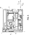
- FIG. 5 is a right side view illustrating the pull-out type heating cooking apparatus 100.
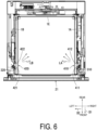
- FIG. 6 is a cross-sectional view illustrating the pull-out type heating cooking apparatus 100 taken along section line VI in FIG. 5 .
- FIG. 5 illustrates the pull-out type heating cooking apparatus 100 from which the right outer wall 1G, the left outer wall 1H, the top outer wall 1J, the bottom outer wall 1F, and the back outer wall 1K are removed.
- the pull-out type heating cooking apparatus 100 further includes a first recessed portion 410 and a first light source unit 310.
- the first recessed portion 410 is located in the right wall 1A.
- the first recessed portion 410 is recessed from the right wall 1A.
- the first recessed portion 410 is recessed from the right wall 1A in a direction opposite to the second direction D2.
- the first light source unit 310 emits light LA in a direction opposite to the first direction D1 in the heating cooking chamber 100A. In other words, the first light source unit 310 emits the light LA toward the back wall 1E of the heating cooking chamber 100A. The first light source unit 310 also emits the light LA toward the left wall 1B of the heating cooking chamber 100A.
- the first light source unit 310 emits the light LA in a direction opposite to the first direction D1 in the heating cooking chamber 100A, the inside of the heating cooking chamber 100A or the object H to be heated that is accommodated in the heating cooking chamber 100A is irradiated with the light LA. As a result, the inside of the heating cooking chamber 100A or the object H to be heated that is accommodated in the heating cooking chamber 100A can be observed in detail.
- the first recessed portion 410 is located on an upper side of the right wall 1A. Specifically, the first recessed portion 410 is located above an upper end of the right side plate portion 23C. The first recessed portion 410 is located on a front side of the right wall 1A. As a result, the inside of the heating cooking chamber 100 A or the object H to be heated that is accommodated in the heating cooking chamber 100A can be observed in more detail.
- FIG. 7 is an enlarged cross-sectional view illustrating the pull-out type heating cooking apparatus 100 of FIG. 6 .
- the first recessed portion 410 includes a first inclined wall 411 and a third inclined wall 412.
- Each of the first inclined wall 411 and the third inclined wall 412 is inclined with respect to the right wall 1A. Specifically, the first inclined wall 411 faces the back wall 1E. The third inclined wall 412 faces the opening portion 100B.
- the side of the third inclined wall 412 in a direction opposite to the first direction D1 is coupled to the right wall 1A.
- the third inclined wall 412 extends in a direction opposite to the second direction D2 as the third inclined wall 412 extends in the first direction D1.
- the side of the first inclined wall 411 in the first direction D1 is coupled to the right wall 1A.
- the first inclined wall 411 extends in a direction opposite to the second direction D2 as the first inclined wall 411 extends in a direction opposite to the first direction D1.
- the side of the third inclined wall 412 in the first direction D1 and the side of the first inclined wall 411 in a direction opposite to the first direction D1 are coupled.
- the first light source unit 310 is disposed on the first inclined wall 411.
- the first light source unit 310 emits the light LA toward the back wall 1E of the heating cooking chamber 100A.
- the first light source unit 310 emits the expanded light beam LA.
- the cross-sectional shape of the expanded light beam LA is substantially circular in a plane perpendicular to the traveling direction of the expanded light beam LA.
- the cross-sectional dimensions of the expanded light beam LA in the plane perpendicular to the traveling direction of the expanded light beam LA increase as the expanded light beam LA travels in the traveling direction.
- the first light source unit 310 emits the light LA toward the back wall 1E of the heating cooking chamber 100A
- the back wall 1E of the heating cooking chamber 100A is irradiated with the light LA.
- the back wall 1E of the heating cooking chamber 100A can be observed in detail.
- the first inclined wall 411 includes a communication hole 411a and a tubular portion 411b.
- the inside and the outside of the heating cooking chamber 100A communicate with each other through the communication hole 411a.
- the communication hole 411a has a circular shape.
- the tubular portion 411b extends from the communication hole 411a toward the outside of the heating cooking chamber 100A. Specifically, the tubular portion 411b has a truncated conical shape. Further, the tubular portion 411b becomes smaller as the tubular portion 411b extends toward the outside of the heating cooking chamber 100A.
- the first light source unit 310 is disposed outside the heating cooking chamber 100A and faces the tubular portion 411b. As a result, the distance between the first light source unit 310 and the back wall 1E increases. Thus, the cross-sectional dimensions of the expanded light beam LA in the heating cooking chamber 100A can be increased. As a result, a wide range of the back wall 1E of the heating cooking chamber 100A or the object H to be heated that is accommodated in the heating cooking chamber 100A can be observed in detail. Moreover, forming the tubular portion 411b into a truncated conical shape can suppress leakage of microwaves to the outside of the heating cooking chamber 100A.
- FIG. 8 is a perspective view illustrating the first light source unit 310.
- FIG. 9 is an exploded perspective view illustrating the first light source unit 310.
- the first light source unit 310 includes a light source substrate 311, a glass plate 314, and an attachment member 316.
- the attachment member 316 has a thermal conductivity lower than the thermal conductivity of the first inclined wall 411.
- the material of the attachment member 316 is, for example, a metal having a thermal conductivity lower than the thermal conductivity of the first inclined wall 411.
- the attachment member 316 includes a plurality of wall portions 317 made of a metal and a third metal plate 316c.
- the third metal plate 316c is disposed between the plurality of wall portions 317.
- the plurality of wall portions 317 include a first metal plate 316a and a second metal plate 316b.
- the first metal plate 316a and the second metal plate 316b face each other.
- the third metal plate 316c is disposed between the first metal plate 316a and the second metal plate 316b.
- the third metal plate 316c is orthogonal to each of the first metal plate 316a and the second metal plate 316b.
- the third metal plate 316c includes a circular through hole 316d.
- the third metal plate 316c is attached to the first inclined wall 411 with a screw or the like.
- the tubular portion 411b passes through the through hole 316d.
- the light source substrate 311 further includes, for example, a light emitting diode (LED) 311a.
- the LED 311a corresponds to an example of "light source”.
- the light source substrate 311 is attached to the first inclined wall 411 via the attachment member 316. Specifically, the light source substrate 311 is attached to the first metal plate 316a and the second metal plate 316b.
- the light LA passes through the glass plate 314.
- the glass plate 314 has a rectangular parallelepiped shape.
- the glass plate 314 is disposed between the tubular portion 411b and the light source substrate 311.
- the light source substrate 311 is attached to the first inclined wall 411 via the attachment member 316, it is possible to suppress heat transfer from the first inclined wall 411 to the light source substrate 311. As a result, it is possible to suppress breakage of the light source substrate 311 by heat.
- the first light source unit 310 further includes a case 312, a metal member 313, and a packing 315.
- the packing 315 is disposed on the outer periphery of the glass plate 314.
- the material of the packing 315 is, for example, rubber.
- the metal member 313 includes a communication hole 313a, a tubular portion 313b, and a metal plate 313c.
- the material of the metal member 313 is, for example, a metal having a thermal conductivity lower than the thermal conductivity of the first inclined wall 411.
- the communication hole 313a is located in the metal plate 313c.
- the inside and the outside of the heating cooking chamber 100A communicate with each other through the communication hole 313a.
- the communication hole 313a has a circular shape.
- the size of the communication hole 313a is smaller than the size of the communication hole 411a.
- the metal plate 313c faces the third metal plate 316c.
- the tubular portion 411b is surrounded by the metal member 313 and the attachment member 316 except for a portion corresponding to the communication hole 313a.
- the tubular portion 313b extends from the communication hole 313a toward the outside of the heating cooking chamber 100A. Specifically, the tubular portion 313b has a truncated conical shape. Further, the tubular portion 313b becomes smaller as the tubular portion 313b extends toward the outside of the heating cooking chamber 100A. As a result, the distance between the light source substrate 311 and the back wall 1E increases. Thus, the cross-sectional dimensions of the expanded light beam LA in the heating cooking chamber 100A can be increased. As a result, a wide range of the back wall 1E of the heating cooking chamber 100A can be observed in more detail.
- overlapping the metal member 313 with the attachment member 316 covers the opening portion of the communication hole 411a, and reducing the size of the communication hole 313a further suppresses leakage of microwaves to the outside of the heating cooking chamber 100A.
- the tubular portion 313b allows the light source substrate 311 and the glass plate 314 to be disposed apart from each other, and thus a heat insulating layer of air can be provided between the light source substrate 3 11 and the glass plate 314, which can further suppress heat conduction to the light source substrate 311.
- the light source substrate 311 is attached to the case 312. Further, the case 312 is attached to the first metal plate 316a and the second metal plate 316b.
- the material of the case 312 is, for example, a synthetic resin. As a result, heat transfer from the first inclined wall 411 to the light source substrate 311 can be further suppressed.
- the light source substrate 311 can be rigidly fixed to the first metal plate 316a and the second metal plate 316b.
- a second light source unit 320 will be described in detail with reference to FIG. 6 again.
- the pull-out type heating cooking apparatus 100 further includes a second recessed portion 420 and the second light source unit 320.
- the second recessed portion 420 is located in the left wall 1B.
- the second recessed portion 420 is recessed from the left wall 1B.
- the second recessed portion 420 is recessed from the left wall 1B in the second direction D2.
- the second light source unit 320 emits light LB in a direction opposite to the first direction D1 in the heating cooking chamber 100A. In other words, the second light source unit 320 emits the light LB toward the back wall 1E of the heating cooking chamber 100A. The second light source unit 320 also emits the light LB toward the right wall 1A of the heating cooking chamber 100A.
- the second recessed portion 420 includes a second inclined wall 421 and a fourth inclined wall 422.
- Each of the second inclined wall 421 and the fourth inclined wall 422 is inclined with respect to the left wall 1B.
- the second inclined wall 421 faces the back wall 1E.
- the fourth inclined wall 422 faces the opening portion 100B.
- the side of the fourth inclined wall 422 in a direction opposite to the first direction D1 is coupled to the left wall 1B.
- the fourth inclined wall 422 extends in the second direction D2 as the fourth inclined wall extends in the first direction D1.
- the side of the second inclined wall 421 in the first direction D1 is coupled to the left wall 1B.
- the second inclined wall 421 extends in the second direction D2 as the second inclined wall 421 extends in a direction opposite to the first direction D1.
- the side of the fourth inclined wall 422 in the first direction D1 and the side of the second inclined wall 421 in a direction opposite to the first direction D1 are coupled.
- the second light source unit 320 is disposed on the second inclined wall 421.
- the second light source unit 320 emits the light LB toward the back wall 1E of the heating cooking chamber 100A.
- the second light source unit 320 emits the expanded light beam LB.
- the cross-sectional shape of the expanded light beam LB is substantially circular in a plane perpendicular to the traveling direction of the expanded light beam LB.
- the cross-sectional dimensions of the expanded light beam LB in the plane perpendicular to the traveling direction of the expanded light beam LB increase as the expanded light beam LB travels in the traveling direction.
- the first light source unit 310 emits the light LA from the right wall 1A in a direction opposite to the first direction D1 in the heating cooking chamber 100A
- the second light source unit 320 emits the light LB from the left wall 1B in a direction opposite to the first direction D1 in the heating cooking chamber 100A, so that the inside of the heating cooking chamber 100A or the object H to be heated that is accommodated in the heating cooking chamber 100A can be observed in more detail.
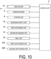
- FIG. 10 is a block diagram illustrating a configuration of the pull-out type heating cooking apparatus 100 according to the present embodiment.
- a control unit 5 controls the first air sending unit 14, the second air sending unit 13, the grill unit 16, the microwave supply unit 15, the first light source unit 310, the second light source unit 320, the drive motor 41, the operation panel 3, and a storage unit 6 by executing control programs stored in the storage unit 6.
- control unit 5 controls the first light source unit 310 and the second light source unit 320 when the lid portion 21 is located at the open position. As a result, the inside of the heating cooking chamber 100A can be observed in detail. In addition, the control unit 5 controls the first light source unit 310 and the second light source unit 320 when the object H to be heated is heated and cooked. As a result, the object H to be heated that is accommodated in the heating cooking chamber 100A can be observed in detail.
- FIG. 11 is a diagram illustrating an appearance of the cabinet 200 to which the pull-out type heating cooking apparatus 100 according to the present embodiment is attached.
- the pull-out type heating cooking apparatus 100 is installed in the cabinet 200 in a built-in manner.
- the cabinet 200 includes an upper wall 200A, a lower wall 200B, a right wall 200C, a left wall 200D, and a rear wall 200E.
- the upper wall 200A, the lower wall 200B, the right wall 200C, the left wall 200D, and the rear wall 200E form an accommodation portion 200F.
- the accommodation portion 200F is a rectangular parallelepiped space into which the pull-out type heating cooking apparatus 100 is fitted.
- the first recessed portion 410 is located in the right wall 1A and the first light source unit 310 is located on the right wall 1A, but the present invention is not limited thereto.
- the first recessed portion 410 may be located in the top wall 1C, the bottom wall 1D, or the left wall 1B and the first light source unit 310 may be located on the top wall 1C, the bottom wall 1D, or the left wall 1B.
- the present invention provides a heating cooking apparatus, and the provided heating cooking apparatus has industrial applicability.
Landscapes
- Physics & Mathematics (AREA)
- Electromagnetism (AREA)
- Engineering & Computer Science (AREA)
- Chemical & Material Sciences (AREA)
- Combustion & Propulsion (AREA)
- Mechanical Engineering (AREA)
- General Engineering & Computer Science (AREA)
- Electric Stoves And Ranges (AREA)
- Electric Ovens (AREA)
Abstract
Description
- The present invention relates to a heating cooking apparatus.
-
PTL 1 discloses a heating cooking device. The heating cooking device disclosed inPTL 1 includes a heating chamber and a light source. The heating chamber accommodates an object to be heated. The light source is disposed on a ceiling portion of the heating chamber. The light source emits light in the heating chamber. - PTL 1:
JP 2017-129295 A - However, in the heating cooking device disclosed in
PTL 1, the light source emits light in a direction orthogonal to the ceiling. Thus, the inside of a heating cooking chamber such as a heating chamber or an object to be heated that is accommodated in the heating cooking chamber cannot be observed in detail from an opening portion side of the heating cooking device. - In light of the above problem, an object of the present invention is to provide a heating cooking apparatus that allows detailed observation of the inside of a heating cooking chamber or an object to be heated that is accommodated in the heating cooking chamber.
- According to an aspect of the present invention, a heating cooking apparatus includes a heating cooking chamber, a first recessed portion, and a first light source unit. The heating cooking chamber includes an opening portion opening in a predetermined direction, a back wall disposed in a direction opposite to the predetermined direction with respect to the opening portion, and a plurality of walls extending from the back wall in the predetermined direction. The first recessed portion is located in a first wall of the plurality of walls and recessed from the first wall. The first recessed portion includes a first inclined wall inclined with respect to the first wall. The first light source unit is disposed on the first inclined wall. The first light source unit emits light toward the back wall of the heating cooking chamber.
- The heating cooking apparatus of the present invention allows detailed observation of the inside of the heating cooking chamber or an object to be heated that is accommodated in the heating cooking chamber.
-
-
FIG. 1 is a perspective view illustrating a pull-out type heating cooking apparatus according to an embodiment of the present invention. -
FIG. 2 is a right side view illustrating the pull-out type heating cooking apparatus according to the present embodiment. -
FIG. 3 is a top view illustrating the pull-out type heating cooking apparatus according to the present embodiment. -
FIG. 4 is an exploded perspective view illustrating a pull-out body according to the present embodiment. -
FIG. 5 is a right side view illustrating the pull-out type heating cooking apparatus according to the present embodiment. -
FIG. 6 is a cross-sectional view illustrating the pull-out type heating cooking apparatus taken along section line VI inFIG. 5 . -
FIG. 7 is an enlarged cross-sectional view illustrating the pull-out type heating cooking apparatus ofFIG. 6 . -
FIG. 8 is a perspective view illustrating a first light source unit according to the present embodiment. -
FIG. 9 is an exploded perspective view illustrating the first light source unit according to the present embodiment. -
FIG. 10 is a block diagram illustrating a configuration of the pull-out type heating cooking apparatus according to the present embodiment. -
FIG. 11 is a perspective view illustrating an appearance of a cabinet to which the pull-out type heating cooking apparatus according to the present embodiment is attached. - Hereinafter, embodiments of a pull-out type heating cooking apparatus according to the present invention will be described with reference to the drawings. Note that, in the drawings, the same or equivalent components are denoted by the same reference signs, and description thereof will not be repeated.
- A pull-out type
heating cooking apparatus 100 will be described with reference toFIG. 1 to FIG. 3 .FIG. 1 is a perspective view illustrating the pull-out typeheating cooking apparatus 100.FIG. 2 is a right side view illustrating the pull-out typeheating cooking apparatus 100.FIG. 3 is a top view illustrating the pull-out typeheating cooking apparatus 100. More specifically,FIG. 1 to FIG. 3 illustrate the pull-out typeheating cooking apparatus 100 in a state where a pull-outbody 2 is pulled out. Further,FIG. 1 illustrates an external appearance of the pull-out typeheating cooking apparatus 100 as viewed diagonally from the upper front right. The pull-out typeheating cooking apparatus 100 is an example of "heating cooking apparatus". - As illustrated in
FIG. 1 , the pull-out typeheating cooking apparatus 100 heats and cooks an object H to be heated. The object H to be heated is, for example, a foodstuff. The pull-out typeheating cooking apparatus 100 includes aheating chamber 1, the pull-outbody 2, anoperation panel 3, and aheating cooking chamber 100A. - In the present embodiment, a side on which the
operation panel 3 of the pull-out typeheating cooking apparatus 100 is disposed is defined as a front side of the pull-out typeheating cooking apparatus 100, and a side opposite to the front side (rear face side) is defined as a rear side of the pull-out typeheating cooking apparatus 100. Further, a right side when the pull-out typeheating cooking apparatus 100 is viewed from the front side is defined as a right side of the pull-out typeheating cooking apparatus 100, and a side opposite to the right side is defined as a left side of the pull-out typeheating cooking apparatus 100. Further, in a direction orthogonal to a front-rear direction and a left-right direction of the pull-out typeheating cooking apparatus 100, a side on which theoperation panel 3 is disposed is defined as an upper side of the pull-out typeheating cooking apparatus 100, and a side opposite to the upper side (bottom side) is defined as a lower side of the pull-out typeheating cooking apparatus 100. Note that these orientations do not limit an orientation of the pull-out typeheating cooking apparatus 100 in use. - As illustrated in
FIG. 1 to FIG. 3 , theheating chamber 1 is a box-like member. Specifically, theheating chamber 1 includes a rightouter wall 1G, a leftouter wall 1H, a topouter wall 1J, a bottomouter wall 1F, and a backouter wall 1K. Theheating chamber 1 accommodates theheating cooking chamber 100A. - The pull-out
body 2, on which the object H to be heated is placed, can be pulled out in afirst direction D 1 from theheating cooking chamber 100A. The first direction D1 is an example of "predetermined direction". The first direction D1 is the forward direction. A third direction D3 intersects the first direction D1. In the present embodiment, the third direction D3 is orthogonal to the first direction D1. In the present embodiment, the third direction D3 is an upward direction (direction opposite to a vertical direction). Specifically, the pull-outbody 2 includes alid portion 21, a placingportion 22, and asupport portion 23. - The
heating cooking chamber 100A includes anaccommodation space 120 that accommodates the object H to be heated. The shape of theheating cooking chamber 100A is, for example, a substantially rectangular parallelepiped shape. Specifically, theheating cooking chamber 100A includes a pair of side wall portions 10, aback wall 1E, and anopening portion 100B. The pair of side wall portions 10 correspond to an example of "a plurality of walls". Theopening portion 100B opens in the first direction D1. Theopening portion 100B communicates with the outside of theheating cooking chamber 100A. Theback wall 1E is disposed in a direction opposite to the first direction D1 with respect to theopening portion 100B. That is, theopening portion 100B faces theback wall 1E. - The pair of side wall portions 10 extend from the
back wall 1E in the first direction D1. Moreover, the pair of side wall portions 10 face each other in a second direction D2. The second direction D2 is the left direction. Specifically, the pair of side wall portions 10 include aright wall 1A and aleft wall 1B. Theright wall 1A corresponds to an example of "first wall". Theleft wall 1B corresponds to an example of "second wall". Theheating cooking chamber 100A further includes atop wall 1C and abottom wall 1D. Materials of theright wall 1A, theleft wall 1B, thetop wall 1C, thebottom wall 1D, and theback wall 1E are, for example, a metal. - The
heating chamber 1 further includes a space R between theheating chamber 1 and theheating cooking chamber 100A. Specifically, theheating chamber 1 further includes the space R between thebottom wall 1D and the bottomouter wall 1F. Theheating chamber 1 further includes the space R between theright wall 1A and the rightouter wall 1G. Theheating chamber 1 further includes the space R between theleft wall 1B and the leftouter wall 1H. Theheating chamber 1 further includes the space R between thetop wall 1C and the topouter wall 1J. Theheating chamber 1 further includes the space R between theback wall 1E and the backouter wall 1K. - As illustrated in
FIG. 3 , the pull-out typeheating cooking apparatus 100 further includes a pair ofrail members 11. Specifically, one rail member of the pair ofrail members 11 includes a right side rail member 111, and the other rail member of the pair ofrail members 11 includes a left side rail member 112. The right side rail member 111 and the left side rail member 112 face each other in the second direction D2. - Each of the right side rail member 111 and the left side rail member 112 is disposed in the
heating chamber 1. Specifically, each of the right side rail member 111 and the left side rail member 112 is disposed between theheating chamber 1 and theheating cooking chamber 100A. More specifically, the right side rail member 111 is fixed to theright wall 1A in the space R between theright wall 1A and the rightouter wall 1G. The left side rail member 112 is fixed to theleft wall 1B in the space R between theleft wall 1B and the leftouter wall 1H. In particular, each of the right side rail member 111 and the left side rail member 112 extends in the first direction D1. - Meanwhile, the pull-out type
heating cooking apparatus 100 further includes a pair ofslide members 24. Specifically, one slide member of the pair ofslide members 24 includes a right side slide member 241, and the other slide member of the pair ofslide members 24 includes a left side slide member 242. The right side slide member 241 and the left side slide member 242 face each other in the second direction D2. - Each of the right side slide member 241 and the left side slide member 242 is disposed on the
lid portion 21. Specifically, one end portion of the right side slide member 241 is attached to a right edge portion of thelid portion 21. One end portion of the left side slide member 242 is attached to a left edge portion of thelid portion 21. In particular, each of the right side slide member 241 and the left side slide member 242 extends in a direction opposite to the first direction D1 from thelid portion 21. - The right side slide member 241 is slidably supported by the right side rail member 111. The left side slide member 242 is slidably supported by the left side rail member 112.
- As illustrated in
FIG. 2 , the pull-out typeheating cooking apparatus 100 further includes asupport member 25. Thesupport member 25 supports thelid portion 21. One end portion of thesupport member 25 is attached at a center portion of thelid portion 2 1 in the left-right direction and below the placingportion 22. Thesupport member 25 is a plate-like member extending in the direction opposite to the first direction D1 from thelid portion 21. Thesupport member 25 includes a rack portion. The rack portion includes teeth. Thesupport member 25 may be a single plate-like member or a plurality of plate-like members. - Meanwhile, the pull-out type
heating cooking apparatus 100 further includes a drive mechanism 4. The drive mechanism 4 drives thesupport member 25. The drive mechanism 4 is positioned below theheating cooking chamber 100A. Specifically, the drive mechanism 4 is accommodated in the space R between thebottom wall 1D and the bottomouter wall 1F. For example, the drive mechanism 4 includes adrive motor 41, a pinion, and adrive rail 42. Thedrive rail 42 is fixed in the space R between thebottom wall 1D and the bottomouter wall 1F. Thedrive rail 42 is a member whose longitudinal direction is the first direction D1. Thesupport member 25 is slidably supported by thedrive rail 42. Thedrive motor 41 rotates the pinion. - The pinion engages with the rack portion of the
support member 25. Furthermore, thesupport member 25 moves in the first direction D1 as a result of rotation of the pinion. Note that the drive mechanism 4 may drive at least one of thesupport member 25, and the right side slide member 241 and the left side slide member 242. Furthermore, in a case where the right side slide member 241 and the left side slide member 242 are driven, the drive mechanism 4 may be positioned more on the side than theheating cooking chamber 100A. - As illustrated in
FIG. 1 , theoperation panel 3 receives an operation from a user. The operation includes, for example, a cooking method for heating and cooking the object H to be heated, or information about movement of thelid portion 21 between the closed position and the open position thereof. Specifically, theoperation panel 3 includes a display unit, a storage unit, and a control unit. The display unit displays various pieces of information. Specifically, the display unit includes a liquid crystal panel. - As illustrated in
FIG. 2 , the pull-out typeheating cooking apparatus 100 further includes a firstair sending unit 14, a secondair sending unit 13, agrill unit 16, and amicrowave supply unit 15. The firstair sending unit 14 circulates air between the inside of theheating cooking chamber 100A and the firstair sending unit 14. The secondair sending unit 13 circulates air between the inside of theheating cooking chamber 100A and the secondair sending unit 13. Thegrill unit 16 heats and cooks the obj ect H to be heated by conducting heat generated by a heater to the object H to be heated. Themicrowave supply unit 15 supplies microwaves into theheating cooking chamber 100A. - Next, the pull-out
body 2 will be described in detail with reference toFIG. 4. FIG. 4 is an exploded perspective view illustrating the pull-outbody 2 according to the present embodiment. As illustrated inFIG. 4 , the object H to be heated can be placed on the placingportion 22. Specifically, the placingportion 22 includes a placing surface on which the object H to be heated is placed. The material of the placingportion 22 is a non-metal, and is preferably ceramic or glass, for example. - The
support portion 23 is attached to thelid portion 21 and supports a peripheral edge portion of the placingportion 22 such that the placingportion 22 is held in a horizontal state. Specifically, thesupport portion 23 includes abottom plate portion 23A and a pair of wall portions 20. The material of thesupport portion 23 is, for example, a metal. - The
bottom plate portion 23A includes a rectangular opening portion 23A1. The rectangular opening portion 23A1 is located at substantially a center portion of thebottom plate portion 23A. - One wall portion of the pair of wall portions 20 includes a right side plate portion 23C, and the other wall portion of the pair of wall portions 20 includes a left side plate portion 23D. Each of the right side plate portion 23C and the left side plate portion 23D extends in substantially the first direction D1. The right side plate portion 23C and the left side plate portion 23D face each other in substantially the second direction D2. More specifically, the right side plate portion 23C and the left side plate portion 23D extend upward from the peripheral edge portion of the
bottom plate portion 23A. The placingportion 22 is fitted among thelid portion 21, the right side plate portion 23C, and the left side plate portion 23D. The peripheral edge portion of the placingportion 22 is fixed to an upper surface of the peripheral edge portion of thebottom plate portion 23A. - The
support portion 23 further includes a pair ofrollers 23E and a pair ofrollers 23F. The pair ofrollers 23E and the pair ofrollers 23F rotate as the pull-outbody 2 moves. Specifically, one roller of the pair ofrollers 23E includes a right side roller 23E1, and the other roller of the pair ofrollers 23E includes a left side roller 23E2. The right side roller 23E1 and the left side roller 23E2 rotate about a rotation axis along substantially the second direction D2. In addition, the right side roller 23E1 is attached to a rear end portion of the right side plate portion 23C (on a side in a direction opposite to substantially the first direction D1). The left side roller 23E2 is attached to a rear end portion of the left side plate portion 23D. The right side roller 23E1 and the left side roller 23E2 are in contact with thebottom wall 1D. - Also, one roller of the pair of
rollers 23F includes a right side roller 23F1, and the other roller of the pair ofrollers 23F includes a left side roller 23F2. The right side roller 23F1 and the left side roller 23F2 rotate about a rotation axis along substantially the third direction D3. The right side roller 23F1 is attached to the rear end portion of the right side plate portion 23C. The left side roller 23F2 is attached to the rear end portion of the left side plate portion 23D. The right side roller 23F1 is in contact with theright wall 1A. The left side roller 23F2 is in contact with theleft wall 1B. - The placing
portion 22 and thesupport portion 23 are accommodated in theheating cooking chamber 100A when thelid portion 21 is located at the closed position. Thelid portion 21 includes awindow portion 21a. As a result, even when thelid portion 21 is located at the closed position, the object H to be heated can be visually recognized. On the other hand, when thelid portion 21 is located at the open position, the placingportion 22 and thesupport portion 23 are pulled out from the inside of theheating cooking chamber 100A in a state where the pair ofrollers 23E and the pair ofrollers 23F are accommodated in theheating cooking chamber 100A. - Next, the pull-out type
heating cooking apparatus 100 will be described in detail with reference toFIG. 5 andFIG. 6 .FIG. 5 is a right side view illustrating the pull-out typeheating cooking apparatus 100.FIG. 6 is a cross-sectional view illustrating the pull-out typeheating cooking apparatus 100 taken along section line VI inFIG. 5 . In detail,FIG. 5 illustrates the pull-out typeheating cooking apparatus 100 from which the rightouter wall 1G, the leftouter wall 1H, the topouter wall 1J, the bottomouter wall 1F, and the backouter wall 1K are removed. - As illustrated in
FIG. 5 andFIG. 6 , the pull-out typeheating cooking apparatus 100 further includes a first recessedportion 410 and a firstlight source unit 310. - The first recessed
portion 410 is located in theright wall 1A. The first recessedportion 410 is recessed from theright wall 1A. Specifically, the first recessedportion 410 is recessed from theright wall 1A in a direction opposite to the second direction D2. - The first
light source unit 310 emits light LA in a direction opposite to the first direction D1 in theheating cooking chamber 100A. In other words, the firstlight source unit 310 emits the light LA toward theback wall 1E of theheating cooking chamber 100A. The firstlight source unit 310 also emits the light LA toward theleft wall 1B of theheating cooking chamber 100A. - As described above, since the first
light source unit 310 emits the light LA in a direction opposite to the first direction D1 in theheating cooking chamber 100A, the inside of theheating cooking chamber 100A or the object H to be heated that is accommodated in theheating cooking chamber 100A is irradiated with the light LA. As a result, the inside of theheating cooking chamber 100A or the object H to be heated that is accommodated in theheating cooking chamber 100A can be observed in detail. - In more detail, the first recessed
portion 410 is located on an upper side of theright wall 1A. Specifically, the first recessedportion 410 is located above an upper end of the right side plate portion 23C. The first recessedportion 410 is located on a front side of theright wall 1A. As a result, the inside of theheating cooking chamber 100 A or the object H to be heated that is accommodated in theheating cooking chamber 100A can be observed in more detail. - Next, the pull-out type
heating cooking apparatus 100 will be described in detail with reference toFIG. 6 andFIG. 7. FIG. 7 is an enlarged cross-sectional view illustrating the pull-out typeheating cooking apparatus 100 ofFIG. 6 . As illustrated inFIG. 6 andFIG. 7 , the first recessedportion 410 includes a firstinclined wall 411 and a thirdinclined wall 412. - Each of the first
inclined wall 411 and the thirdinclined wall 412 is inclined with respect to theright wall 1A. Specifically, the firstinclined wall 411 faces theback wall 1E. The thirdinclined wall 412 faces theopening portion 100B. - In detail, the side of the third
inclined wall 412 in a direction opposite to the first direction D1 is coupled to theright wall 1A. The thirdinclined wall 412 extends in a direction opposite to the second direction D2 as the thirdinclined wall 412 extends in the first direction D1. On the other hand, the side of the firstinclined wall 411 in the first direction D1 is coupled to theright wall 1A. The firstinclined wall 411 extends in a direction opposite to the second direction D2 as the firstinclined wall 411 extends in a direction opposite to the first direction D1. The side of the thirdinclined wall 412 in the first direction D1 and the side of the firstinclined wall 411 in a direction opposite to the first direction D1 are coupled. - The first
light source unit 310 is disposed on the firstinclined wall 411. The firstlight source unit 310 emits the light LA toward theback wall 1E of theheating cooking chamber 100A. In detail, the firstlight source unit 310 emits the expanded light beam LA. For example, the cross-sectional shape of the expanded light beam LA is substantially circular in a plane perpendicular to the traveling direction of the expanded light beam LA. In addition, the cross-sectional dimensions of the expanded light beam LA in the plane perpendicular to the traveling direction of the expanded light beam LA increase as the expanded light beam LA travels in the traveling direction. - As described above, since the first
light source unit 310 emits the light LA toward theback wall 1E of theheating cooking chamber 100A, theback wall 1E of theheating cooking chamber 100A is irradiated with the light LA. As a result, theback wall 1E of theheating cooking chamber 100A can be observed in detail. - In detail, the first
inclined wall 411 includes acommunication hole 411a and atubular portion 411b. The inside and the outside of theheating cooking chamber 100A communicate with each other through thecommunication hole 411a. Specifically, thecommunication hole 411a has a circular shape. - The
tubular portion 411b extends from thecommunication hole 411a toward the outside of theheating cooking chamber 100A. Specifically, thetubular portion 411b has a truncated conical shape. Further, thetubular portion 411b becomes smaller as thetubular portion 411b extends toward the outside of theheating cooking chamber 100A. - The first
light source unit 310 is disposed outside theheating cooking chamber 100A and faces thetubular portion 411b. As a result, the distance between the firstlight source unit 310 and theback wall 1E increases. Thus, the cross-sectional dimensions of the expanded light beam LA in theheating cooking chamber 100A can be increased. As a result, a wide range of theback wall 1E of theheating cooking chamber 100A or the object H to be heated that is accommodated in theheating cooking chamber 100A can be observed in detail. Moreover, forming thetubular portion 411b into a truncated conical shape can suppress leakage of microwaves to the outside of theheating cooking chamber 100A. - Next, the first
light source unit 310 will be described in detail with reference toFIG. 8 andFIG. 9 .FIG. 8 is a perspective view illustrating the firstlight source unit 310.FIG. 9 is an exploded perspective view illustrating the firstlight source unit 310. As illustrated inFIG. 8 andFIG. 9 , the firstlight source unit 310 includes alight source substrate 311, aglass plate 314, and anattachment member 316. - The
attachment member 316 has a thermal conductivity lower than the thermal conductivity of the firstinclined wall 411. The material of theattachment member 316 is, for example, a metal having a thermal conductivity lower than the thermal conductivity of the firstinclined wall 411. Specifically, theattachment member 316 includes a plurality of wall portions 317 made of a metal and athird metal plate 316c. Thethird metal plate 316c is disposed between the plurality of wall portions 317. In detail, the plurality of wall portions 317 include a first metal plate 316a and a second metal plate 316b. The first metal plate 316a and the second metal plate 316b face each other. Thethird metal plate 316c is disposed between the first metal plate 316a and the second metal plate 316b. Thethird metal plate 316c is orthogonal to each of the first metal plate 316a and the second metal plate 316b. Thethird metal plate 316c includes a circular throughhole 316d. Thethird metal plate 316c is attached to the firstinclined wall 411 with a screw or the like. Thetubular portion 411b passes through the throughhole 316d. - The
light source substrate 311 further includes, for example, a light emitting diode (LED) 311a. TheLED 311a corresponds to an example of "light source". Thelight source substrate 311 is attached to the firstinclined wall 411 via theattachment member 316. Specifically, thelight source substrate 311 is attached to the first metal plate 316a and the second metal plate 316b. - The light LA passes through the
glass plate 314. Specifically, theglass plate 314 has a rectangular parallelepiped shape. Theglass plate 314 is disposed between thetubular portion 411b and thelight source substrate 311. - As described above, since the
light source substrate 311 is attached to the firstinclined wall 411 via theattachment member 316, it is possible to suppress heat transfer from the firstinclined wall 411 to thelight source substrate 311. As a result, it is possible to suppress breakage of thelight source substrate 311 by heat. - In more detail, the first
light source unit 310 further includes acase 312, ametal member 313, and apacking 315. - The packing 315 is disposed on the outer periphery of the
glass plate 314. The material of the packing 315 is, for example, rubber. As a result, theglass plate 314 and thetubular portion 411b can be fixed to each other. - The
metal member 313 includes acommunication hole 313a, atubular portion 313b, and ametal plate 313c. The material of themetal member 313 is, for example, a metal having a thermal conductivity lower than the thermal conductivity of the firstinclined wall 411. Thecommunication hole 313a is located in themetal plate 313c. The inside and the outside of theheating cooking chamber 100A communicate with each other through thecommunication hole 313a. Specifically, thecommunication hole 313a has a circular shape. The size of thecommunication hole 313a is smaller than the size of thecommunication hole 411a. Themetal plate 313c faces thethird metal plate 316c. As a result, thetubular portion 411b is surrounded by themetal member 313 and theattachment member 316 except for a portion corresponding to thecommunication hole 313a. - The
tubular portion 313b extends from thecommunication hole 313a toward the outside of theheating cooking chamber 100A. Specifically, thetubular portion 313b has a truncated conical shape. Further, thetubular portion 313b becomes smaller as thetubular portion 313b extends toward the outside of theheating cooking chamber 100A. As a result, the distance between thelight source substrate 311 and theback wall 1E increases. Thus, the cross-sectional dimensions of the expanded light beam LA in theheating cooking chamber 100A can be increased. As a result, a wide range of theback wall 1E of theheating cooking chamber 100A can be observed in more detail. - In addition, overlapping the
metal member 313 with theattachment member 316 covers the opening portion of thecommunication hole 411a, and reducing the size of thecommunication hole 313a further suppresses leakage of microwaves to the outside of theheating cooking chamber 100A. In addition, thetubular portion 313b allows thelight source substrate 311 and theglass plate 314 to be disposed apart from each other, and thus a heat insulating layer of air can be provided between thelight source substrate 3 11 and theglass plate 314, which can further suppress heat conduction to thelight source substrate 311. - The
light source substrate 311 is attached to thecase 312. Further, thecase 312 is attached to the first metal plate 316a and the second metal plate 316b. The material of thecase 312 is, for example, a synthetic resin. As a result, heat transfer from the firstinclined wall 411 to thelight source substrate 311 can be further suppressed. In addition, thelight source substrate 311 can be rigidly fixed to the first metal plate 316a and the second metal plate 316b. - A second
light source unit 320 will be described in detail with reference toFIG. 6 again. As illustrated inFIG. 6 , the pull-out typeheating cooking apparatus 100 further includes a second recessedportion 420 and the secondlight source unit 320. - The second recessed
portion 420 is located in theleft wall 1B. The second recessedportion 420 is recessed from theleft wall 1B. Specifically, the second recessedportion 420 is recessed from theleft wall 1B in the second direction D2. - The second
light source unit 320 emits light LB in a direction opposite to the first direction D1 in theheating cooking chamber 100A. In other words, the secondlight source unit 320 emits the light LB toward theback wall 1E of theheating cooking chamber 100A. The secondlight source unit 320 also emits the light LB toward theright wall 1A of theheating cooking chamber 100A. - The second recessed
portion 420 includes a secondinclined wall 421 and a fourthinclined wall 422. Each of the secondinclined wall 421 and the fourthinclined wall 422 is inclined with respect to theleft wall 1B. Specifically, the secondinclined wall 421 faces theback wall 1E. The fourthinclined wall 422 faces theopening portion 100B. - In detail, the side of the fourth
inclined wall 422 in a direction opposite to the first direction D1 is coupled to theleft wall 1B. The fourthinclined wall 422 extends in the second direction D2 as the fourth inclined wall extends in the first direction D1. On the other hand, the side of the secondinclined wall 421 in the first direction D1 is coupled to theleft wall 1B. The secondinclined wall 421 extends in the second direction D2 as the secondinclined wall 421 extends in a direction opposite to the first direction D1. The side of the fourthinclined wall 422 in the first direction D1 and the side of the secondinclined wall 421 in a direction opposite to the first direction D1 are coupled. - The second
light source unit 320 is disposed on the secondinclined wall 421. The secondlight source unit 320 emits the light LB toward theback wall 1E of theheating cooking chamber 100A. In detail, the secondlight source unit 320 emits the expanded light beam LB. For example, the cross-sectional shape of the expanded light beam LB is substantially circular in a plane perpendicular to the traveling direction of the expanded light beam LB. Further, the cross-sectional dimensions of the expanded light beam LB in the plane perpendicular to the traveling direction of the expanded light beam LB increase as the expanded light beam LB travels in the traveling direction. - As described above, the first
light source unit 310 emits the light LA from theright wall 1A in a direction opposite to the first direction D1 in theheating cooking chamber 100A, and the secondlight source unit 320 emits the light LB from theleft wall 1B in a direction opposite to the first direction D1 in theheating cooking chamber 100A, so that the inside of theheating cooking chamber 100A or the object H to be heated that is accommodated in theheating cooking chamber 100A can be observed in more detail. - Next, the configuration of the pull-out type
heating cooking apparatus 100 will be described in detail with reference toFIG. 10. FIG. 10 is a block diagram illustrating a configuration of the pull-out typeheating cooking apparatus 100 according to the present embodiment. - As illustrated in
FIG. 10 , acontrol unit 5 controls the firstair sending unit 14, the secondair sending unit 13, thegrill unit 16, themicrowave supply unit 15, the firstlight source unit 310, the secondlight source unit 320, thedrive motor 41, theoperation panel 3, and astorage unit 6 by executing control programs stored in thestorage unit 6. - Specifically, the
control unit 5 controls the firstlight source unit 310 and the secondlight source unit 320 when thelid portion 21 is located at the open position. As a result, the inside of theheating cooking chamber 100A can be observed in detail. In addition, thecontrol unit 5 controls the firstlight source unit 310 and the secondlight source unit 320 when the object H to be heated is heated and cooked. As a result, the object H to be heated that is accommodated in theheating cooking chamber 100A can be observed in detail. - Subsequently, a
cabinet 200 to which the pull-out typeheating cooking apparatus 100 is attached will be described with reference toFIG. 11. FIG. 11 is a diagram illustrating an appearance of thecabinet 200 to which the pull-out typeheating cooking apparatus 100 according to the present embodiment is attached. - The pull-out type
heating cooking apparatus 100 is installed in thecabinet 200 in a built-in manner. As illustrated inFIG. 11 , thecabinet 200 includes anupper wall 200A, alower wall 200B, a right wall 200C, aleft wall 200D, and arear wall 200E. Theupper wall 200A, thelower wall 200B, the right wall 200C, theleft wall 200D, and therear wall 200E form anaccommodation portion 200F. Theaccommodation portion 200F is a rectangular parallelepiped space into which the pull-out typeheating cooking apparatus 100 is fitted. - The embodiment of the present invention has been described above with reference to the accompanying drawings. However, the present invention is not limited to the embodiment described above, and the present invention can be implemented in various modes without departing from the gist thereof. The drawings primarily schematically illustrate each of the constituent elements for the sake of easier understanding, and the thickness, length, quantity, and the like of each of the illustrated constituent elements are different from the actual thickness, length, quantity, and the like by reason of creation of the drawings. Further, the material, shape, dimensions, and the like of each of the constituent elements illustrated in the embodiment described above are merely examples and are not particularly limited, and various modifications can be made within the scope not substantially departing from the effects of the present invention.
- As described with reference to
FIG. 1 to FIG. 11 , the first recessedportion 410 is located in theright wall 1A and the firstlight source unit 310 is located on theright wall 1A, but the present invention is not limited thereto. The first recessedportion 410 may be located in thetop wall 1C, thebottom wall 1D, or theleft wall 1B and the firstlight source unit 310 may be located on thetop wall 1C, thebottom wall 1D, or theleft wall 1B. - The present invention provides a heating cooking apparatus, and the provided heating cooking apparatus has industrial applicability.
-
- 1 Pull-out type heating cooking apparatus (heating cooking apparatus)
- 100A Heating cooking chamber
- 100B Opening portion
- 1A Right wall (first wall)
- 1B Left wall (second wall)
- 1E Back wall
- 310 First light source unit
- 320 Second light source unit
- 410 First recessed portion
- 411 First inclined wall
- 420 Second recessed portion
- D1 First direction (predetermined direction)
Claims (6)
- A heating cooking apparatus comprising:a heating cooking chamber including an opening portion opening in a predetermined direction, a back wall disposed in a direction opposite to the predetermined direction with respect to the opening portion, and a plurality of walls extending from the back wall in the predetermined direction;a first recessed portion located in a first wall of the plurality of walls and recessed from the first wall; anda first light source unit,wherein the first recessed portion includes a first inclined wall inclined with respect to the first wall,the first light source unit is disposed on the first inclined wall, andthe first light source unit emits light toward the back wall of the heating cooking chamber.
- The heating cooking apparatus according to claim 1, further comprisinga microwave supply unit configured to supply a microwave into the heating cooking chamber,wherein the first inclined wall includesa communication hole through which an inside and an outside of the heating cooking chamber communicate with each other, anda tubular portion extending from the communication hole toward the outside of the heating cooking chamber, andthe first light source unit is disposed outside the heating cooking chamber and faces the tubular portion.
- The heating cooking apparatus according to claim 2,wherein the first light source unit includesa light source substrate including a light source,a glass plate through which the light passes, andan attachment member having a thermal conductivity lower than a thermal conductivity of the first inclined wall,the glass plate is disposed between the tubular portion and the light source substrate, andthe light source substrate is attached to the first inclined wall via the attachment member.
- The heating cooking apparatus according to claim 3,wherein the first light source unit further includes a metal member,the metal member includesa communication hole through which the inside and the outside of the heating cooking chamber communicate with each other, anda tubular portion extending from the communication hole toward the outside of the heating cooking chamber,the metal member is disposed between the glass plate and the light source substrate, anda size of the communication hole of the metal member is smaller than a size of the communication hole of the first inclined wall.
- The heating cooking apparatus according to claim 4,wherein the attachment member includesa plurality of wall portions made of metal, anda metal plate disposed between the plurality of wall portions and including a through hole,the metal member further includes a metal plate in which the communication hole of the metal member is located,the metal plate of the metal member faces the metal plate of the attachment member, andthe tubular portion of the first inclined wall passes through the through hole of the attachment member and is surrounded by the metal member and the attachment member except for a portion corresponding to the communication hole of the metal member.
- The heating cooking apparatus according to any one of claims 1 to 5, further comprising:a second recessed portion located in a second wall of the plurality of walls and recessed from the second wall; anda second light source unit disposed in the second recessed portion,wherein the second wall and the first wall face each other,the second recessed portion includes a second inclined wall inclined with respect to the second wall,the second light source unit is disposed on the second inclined wall, andthe second light source unit emits light toward the back wall of the heating cooking chamber.
Applications Claiming Priority (2)
| Application Number | Priority Date | Filing Date | Title |
|---|---|---|---|
| JP2021030098 | 2021-02-26 | ||
| PCT/JP2022/006928 WO2022181540A1 (en) | 2021-02-26 | 2022-02-21 | Cooker |
Publications (2)
| Publication Number | Publication Date |
|---|---|
| EP4299988A1 true EP4299988A1 (en) | 2024-01-03 |
| EP4299988A4 EP4299988A4 (en) | 2024-06-12 |
Family
ID=83047977
Family Applications (1)
| Application Number | Title | Priority Date | Filing Date |
|---|---|---|---|
| EP22759576.6A Pending EP4299988A4 (en) | 2021-02-26 | 2022-02-21 | Cooker |
Country Status (5)
| Country | Link |
|---|---|
| US (1) | US20240306271A1 (en) |
| EP (1) | EP4299988A4 (en) |
| JP (1) | JPWO2022181540A1 (en) |
| CA (1) | CA3208663A1 (en) |
| WO (1) | WO2022181540A1 (en) |
Family Cites Families (4)
| Publication number | Priority date | Publication date | Assignee | Title |
|---|---|---|---|---|
| JP2013257061A (en) * | 2012-06-12 | 2013-12-26 | Sharp Corp | Microwave oven |
| JP6013086B2 (en) * | 2012-08-24 | 2016-10-25 | シャープ株式会社 | Cooker |
| JP7029706B2 (en) * | 2018-02-28 | 2022-03-04 | パナソニックIpマネジメント株式会社 | Cooker |
| JP7126046B2 (en) * | 2018-04-27 | 2022-08-26 | パナソニックIpマネジメント株式会社 | heating cooker |
-
2022
- 2022-02-21 US US18/276,064 patent/US20240306271A1/en active Pending
- 2022-02-21 EP EP22759576.6A patent/EP4299988A4/en active Pending
- 2022-02-21 WO PCT/JP2022/006928 patent/WO2022181540A1/en not_active Ceased
- 2022-02-21 JP JP2023502389A patent/JPWO2022181540A1/ja active Pending
- 2022-02-21 CA CA3208663A patent/CA3208663A1/en active Pending
Also Published As
| Publication number | Publication date |
|---|---|
| CA3208663A1 (en) | 2022-09-01 |
| WO2022181540A1 (en) | 2022-09-01 |
| US20240306271A1 (en) | 2024-09-12 |
| JPWO2022181540A1 (en) | 2022-09-01 |
| EP4299988A4 (en) | 2024-06-12 |
Similar Documents
| Publication | Publication Date | Title |
|---|---|---|
| EP4299988A1 (en) | Cooker | |
| US12201240B2 (en) | Heating cooking apparatus | |
| EP4279818A1 (en) | Cooking device | |
| US12516826B2 (en) | Heating cooking apparatus | |
| CN114401653B (en) | Heating cookers and built-in heating cooking systems | |
| EP4006420B1 (en) | Heating cooker | |
| EP4006424B1 (en) | Heating cooker | |
| EP4299987A1 (en) | Thermal cooker | |
| US12446121B2 (en) | Heating cooking apparatus | |
| WO2021020345A1 (en) | Heating cooking device | |
| US12363805B2 (en) | Drawer type heating cooking apparatus | |
| US20240077207A1 (en) | Heating cooking apparatus | |
| CA3166965A1 (en) | Heating cooking device |
Legal Events
| Date | Code | Title | Description |
|---|---|---|---|
| STAA | Information on the status of an ep patent application or granted ep patent |
Free format text: STATUS: THE INTERNATIONAL PUBLICATION HAS BEEN MADE |
|
| PUAI | Public reference made under article 153(3) epc to a published international application that has entered the european phase |
Free format text: ORIGINAL CODE: 0009012 |
|
| STAA | Information on the status of an ep patent application or granted ep patent |
Free format text: STATUS: REQUEST FOR EXAMINATION WAS MADE |
|
| 17P | Request for examination filed |
Effective date: 20230919 |
|
| AK | Designated contracting states |
Kind code of ref document: A1 Designated state(s): AL AT BE BG CH CY CZ DE DK EE ES FI FR GB GR HR HU IE IS IT LI LT LU LV MC MK MT NL NO PL PT RO RS SE SI SK SM TR |
|
| DAV | Request for validation of the european patent (deleted) | ||
| DAX | Request for extension of the european patent (deleted) | ||
| A4 | Supplementary search report drawn up and despatched |
Effective date: 20240513 |
|
| RIC1 | Information provided on ipc code assigned before grant |
Ipc: H05B 6/64 20060101ALI20240506BHEP Ipc: F24C 15/00 20060101ALI20240506BHEP Ipc: F24C 15/18 20060101ALI20240506BHEP Ipc: F24C 7/04 20210101ALI20240506BHEP Ipc: F24C 7/02 20060101AFI20240506BHEP |