EP4299914A2 - Waterproof electronic device and fan device thereof - Google Patents
Waterproof electronic device and fan device thereof Download PDFInfo
- Publication number
- EP4299914A2 EP4299914A2 EP23156787.6A EP23156787A EP4299914A2 EP 4299914 A2 EP4299914 A2 EP 4299914A2 EP 23156787 A EP23156787 A EP 23156787A EP 4299914 A2 EP4299914 A2 EP 4299914A2
- Authority
- EP
- European Patent Office
- Prior art keywords
- fan
- waterproof
- connecting device
- cable
- disposed
- Prior art date
- Legal status (The legal status is an assumption and is not a legal conclusion. Google has not performed a legal analysis and makes no representation as to the accuracy of the status listed.)
- Granted
Links
Images




Classifications
-
- F—MECHANICAL ENGINEERING; LIGHTING; HEATING; WEAPONS; BLASTING
- F04—POSITIVE - DISPLACEMENT MACHINES FOR LIQUIDS; PUMPS FOR LIQUIDS OR ELASTIC FLUIDS
- F04D—NON-POSITIVE-DISPLACEMENT PUMPS
- F04D25/00—Pumping installations or systems
- F04D25/02—Units comprising pumps and their driving means
- F04D25/06—Units comprising pumps and their driving means the pump being electrically driven
- F04D25/0693—Details or arrangements of the wiring
-
- G—PHYSICS
- G06—COMPUTING OR CALCULATING; COUNTING
- G06F—ELECTRIC DIGITAL DATA PROCESSING
- G06F1/00—Details not covered by groups G06F3/00 - G06F13/00 and G06F21/00
- G06F1/16—Constructional details or arrangements
- G06F1/1613—Constructional details or arrangements for portable computers
- G06F1/1633—Constructional details or arrangements of portable computers not specific to the type of enclosures covered by groups G06F1/1615 - G06F1/1626
- G06F1/1656—Details related to functional adaptations of the enclosure, e.g. to provide protection against EMI, shock, water, or to host detachable peripherals like a mouse or removable expansions units like PCMCIA cards, or to provide access to internal components for maintenance or to removable storage supports like CDs or DVDs, or to mechanically mount accessories
- G06F1/1658—Details related to functional adaptations of the enclosure, e.g. to provide protection against EMI, shock, water, or to host detachable peripherals like a mouse or removable expansions units like PCMCIA cards, or to provide access to internal components for maintenance or to removable storage supports like CDs or DVDs, or to mechanically mount accessories related to the mounting of internal components, e.g. disc drive or any other functional module
-
- F—MECHANICAL ENGINEERING; LIGHTING; HEATING; WEAPONS; BLASTING
- F04—POSITIVE - DISPLACEMENT MACHINES FOR LIQUIDS; PUMPS FOR LIQUIDS OR ELASTIC FLUIDS
- F04D—NON-POSITIVE-DISPLACEMENT PUMPS
- F04D17/00—Radial-flow pumps, e.g. centrifugal pumps; Helico-centrifugal pumps
- F04D17/08—Centrifugal pumps
- F04D17/16—Centrifugal pumps for displacing without appreciable compression
-
- F—MECHANICAL ENGINEERING; LIGHTING; HEATING; WEAPONS; BLASTING
- F04—POSITIVE - DISPLACEMENT MACHINES FOR LIQUIDS; PUMPS FOR LIQUIDS OR ELASTIC FLUIDS
- F04D—NON-POSITIVE-DISPLACEMENT PUMPS
- F04D25/00—Pumping installations or systems
- F04D25/02—Units comprising pumps and their driving means
- F04D25/06—Units comprising pumps and their driving means the pump being electrically driven
- F04D25/0606—Units comprising pumps and their driving means the pump being electrically driven the electric motor being specially adapted for integration in the pump
- F04D25/0613—Units comprising pumps and their driving means the pump being electrically driven the electric motor being specially adapted for integration in the pump the electric motor being of the inside-out type, i.e. the rotor is arranged radially outside a central stator
-
- F—MECHANICAL ENGINEERING; LIGHTING; HEATING; WEAPONS; BLASTING
- F04—POSITIVE - DISPLACEMENT MACHINES FOR LIQUIDS; PUMPS FOR LIQUIDS OR ELASTIC FLUIDS
- F04D—NON-POSITIVE-DISPLACEMENT PUMPS
- F04D29/00—Details, component parts, or accessories
- F04D29/08—Sealings
- F04D29/083—Sealings especially adapted for elastic fluid pumps
-
- F—MECHANICAL ENGINEERING; LIGHTING; HEATING; WEAPONS; BLASTING
- F04—POSITIVE - DISPLACEMENT MACHINES FOR LIQUIDS; PUMPS FOR LIQUIDS OR ELASTIC FLUIDS
- F04D—NON-POSITIVE-DISPLACEMENT PUMPS
- F04D29/00—Details, component parts, or accessories
- F04D29/60—Mounting; Assembling; Disassembling
- F04D29/601—Mounting; Assembling; Disassembling specially adapted for elastic fluid pumps
-
- F—MECHANICAL ENGINEERING; LIGHTING; HEATING; WEAPONS; BLASTING
- F04—POSITIVE - DISPLACEMENT MACHINES FOR LIQUIDS; PUMPS FOR LIQUIDS OR ELASTIC FLUIDS
- F04D—NON-POSITIVE-DISPLACEMENT PUMPS
- F04D29/00—Details, component parts, or accessories
- F04D29/60—Mounting; Assembling; Disassembling
- F04D29/601—Mounting; Assembling; Disassembling specially adapted for elastic fluid pumps
- F04D29/602—Mounting in cavities
-
- F—MECHANICAL ENGINEERING; LIGHTING; HEATING; WEAPONS; BLASTING
- F04—POSITIVE - DISPLACEMENT MACHINES FOR LIQUIDS; PUMPS FOR LIQUIDS OR ELASTIC FLUIDS
- F04D—NON-POSITIVE-DISPLACEMENT PUMPS
- F04D29/00—Details, component parts, or accessories
- F04D29/70—Suction grids; Strainers; Dust separation; Cleaning
- F04D29/701—Suction grids; Strainers; Dust separation; Cleaning especially adapted for elastic fluid pumps
- F04D29/703—Suction grids; Strainers; Dust separation; Cleaning especially adapted for elastic fluid pumps specially for fans, e.g. fan guards
-
- F—MECHANICAL ENGINEERING; LIGHTING; HEATING; WEAPONS; BLASTING
- F04—POSITIVE - DISPLACEMENT MACHINES FOR LIQUIDS; PUMPS FOR LIQUIDS OR ELASTIC FLUIDS
- F04D—NON-POSITIVE-DISPLACEMENT PUMPS
- F04D29/00—Details, component parts, or accessories
- F04D29/70—Suction grids; Strainers; Dust separation; Cleaning
- F04D29/701—Suction grids; Strainers; Dust separation; Cleaning especially adapted for elastic fluid pumps
- F04D29/706—Humidity separation
-
- G—PHYSICS
- G06—COMPUTING OR CALCULATING; COUNTING
- G06F—ELECTRIC DIGITAL DATA PROCESSING
- G06F1/00—Details not covered by groups G06F3/00 - G06F13/00 and G06F21/00
- G06F1/16—Constructional details or arrangements
- G06F1/1613—Constructional details or arrangements for portable computers
- G06F1/1633—Constructional details or arrangements of portable computers not specific to the type of enclosures covered by groups G06F1/1615 - G06F1/1626
- G06F1/1656—Details related to functional adaptations of the enclosure, e.g. to provide protection against EMI, shock, water, or to host detachable peripherals like a mouse or removable expansions units like PCMCIA cards, or to provide access to internal components for maintenance or to removable storage supports like CDs or DVDs, or to mechanically mount accessories
-
- G—PHYSICS
- G06—COMPUTING OR CALCULATING; COUNTING
- G06F—ELECTRIC DIGITAL DATA PROCESSING
- G06F1/00—Details not covered by groups G06F3/00 - G06F13/00 and G06F21/00
- G06F1/16—Constructional details or arrangements
- G06F1/20—Cooling means
- G06F1/203—Cooling means for portable computers, e.g. for laptops
-
- H—ELECTRICITY
- H01—ELECTRIC ELEMENTS
- H01R—ELECTRICALLY-CONDUCTIVE CONNECTIONS; STRUCTURAL ASSOCIATIONS OF A PLURALITY OF MUTUALLY-INSULATED ELECTRICAL CONNECTING ELEMENTS; COUPLING DEVICES; CURRENT COLLECTORS
- H01R13/00—Details of coupling devices of the kinds covered by groups H01R12/70 or H01R24/00 - H01R33/00
- H01R13/46—Bases; Cases
- H01R13/52—Dustproof, splashproof, drip-proof, waterproof, or flameproof cases
- H01R13/5205—Sealing means between cable and housing, e.g. grommet
- H01R13/5208—Sealing means between cable and housing, e.g. grommet having at least two cable receiving openings
-
- H—ELECTRICITY
- H01—ELECTRIC ELEMENTS
- H01R—ELECTRICALLY-CONDUCTIVE CONNECTIONS; STRUCTURAL ASSOCIATIONS OF A PLURALITY OF MUTUALLY-INSULATED ELECTRICAL CONNECTING ELEMENTS; COUPLING DEVICES; CURRENT COLLECTORS
- H01R33/00—Coupling devices specially adapted for supporting apparatus and having one part acting as a holder providing support and electrical connection via a counterpart which is structurally associated with the apparatus, e.g. lamp holders; Separate parts thereof
- H01R33/965—Dustproof, splashproof, drip-proof, waterproof, or flameproof holders
-
- H—ELECTRICITY
- H05—ELECTRIC TECHNIQUES NOT OTHERWISE PROVIDED FOR
- H05K—PRINTED CIRCUITS; CASINGS OR CONSTRUCTIONAL DETAILS OF ELECTRIC APPARATUS; MANUFACTURE OF ASSEMBLAGES OF ELECTRICAL COMPONENTS
- H05K7/00—Constructional details common to different types of electric apparatus
- H05K7/20—Modifications to facilitate cooling, ventilating, or heating
- H05K7/20009—Modifications to facilitate cooling, ventilating, or heating using a gaseous coolant in electronic enclosures
- H05K7/20136—Forced ventilation, e.g. by fans
- H05K7/20145—Means for directing air flow, e.g. ducts, deflectors, plenum or guides
-
- H—ELECTRICITY
- H05—ELECTRIC TECHNIQUES NOT OTHERWISE PROVIDED FOR
- H05K—PRINTED CIRCUITS; CASINGS OR CONSTRUCTIONAL DETAILS OF ELECTRIC APPARATUS; MANUFACTURE OF ASSEMBLAGES OF ELECTRICAL COMPONENTS
- H05K7/00—Constructional details common to different types of electric apparatus
- H05K7/20—Modifications to facilitate cooling, ventilating, or heating
- H05K7/20009—Modifications to facilitate cooling, ventilating, or heating using a gaseous coolant in electronic enclosures
- H05K7/20136—Forced ventilation, e.g. by fans
- H05K7/20154—Heat dissipaters coupled to components
-
- H—ELECTRICITY
- H05—ELECTRIC TECHNIQUES NOT OTHERWISE PROVIDED FOR
- H05K—PRINTED CIRCUITS; CASINGS OR CONSTRUCTIONAL DETAILS OF ELECTRIC APPARATUS; MANUFACTURE OF ASSEMBLAGES OF ELECTRICAL COMPONENTS
- H05K7/00—Constructional details common to different types of electric apparatus
- H05K7/20—Modifications to facilitate cooling, ventilating, or heating
- H05K7/20009—Modifications to facilitate cooling, ventilating, or heating using a gaseous coolant in electronic enclosures
- H05K7/20136—Forced ventilation, e.g. by fans
- H05K7/20172—Fan mounting or fan specifications
-
- G—PHYSICS
- G06—COMPUTING OR CALCULATING; COUNTING
- G06F—ELECTRIC DIGITAL DATA PROCESSING
- G06F2200/00—Indexing scheme relating to G06F1/04 - G06F1/32
- G06F2200/20—Indexing scheme relating to G06F1/20
- G06F2200/201—Cooling arrangements using cooling fluid
-
- H—ELECTRICITY
- H01—ELECTRIC ELEMENTS
- H01R—ELECTRICALLY-CONDUCTIVE CONNECTIONS; STRUCTURAL ASSOCIATIONS OF A PLURALITY OF MUTUALLY-INSULATED ELECTRICAL CONNECTING ELEMENTS; COUPLING DEVICES; CURRENT COLLECTORS
- H01R2201/00—Connectors or connections adapted for particular applications
- H01R2201/06—Connectors or connections adapted for particular applications for computer periphery
-
- H—ELECTRICITY
- H01—ELECTRIC ELEMENTS
- H01R—ELECTRICALLY-CONDUCTIVE CONNECTIONS; STRUCTURAL ASSOCIATIONS OF A PLURALITY OF MUTUALLY-INSULATED ELECTRICAL CONNECTING ELEMENTS; COUPLING DEVICES; CURRENT COLLECTORS
- H01R33/00—Coupling devices specially adapted for supporting apparatus and having one part acting as a holder providing support and electrical connection via a counterpart which is structurally associated with the apparatus, e.g. lamp holders; Separate parts thereof
- H01R33/74—Devices having four or more poles, e.g. holders for compact fluorescent lamps
-
- H—ELECTRICITY
- H01—ELECTRIC ELEMENTS
- H01R—ELECTRICALLY-CONDUCTIVE CONNECTIONS; STRUCTURAL ASSOCIATIONS OF A PLURALITY OF MUTUALLY-INSULATED ELECTRICAL CONNECTING ELEMENTS; COUPLING DEVICES; CURRENT COLLECTORS
- H01R33/00—Coupling devices specially adapted for supporting apparatus and having one part acting as a holder providing support and electrical connection via a counterpart which is structurally associated with the apparatus, e.g. lamp holders; Separate parts thereof
- H01R33/97—Holders with separate means to prevent loosening of the coupling or unauthorised removal of apparatus held
Definitions
- the present disclosure relates to a waterproof electronic device and a fan device thereof, and more particularly to an electronic device having waterproof and dustproof functions, and a fan device installed in the electronic device.
- An industrial computer (or referred to as a rugged laptop) is usually used outdoors. Since an environment in which the industrial computer is used is generally poor, the industrial computer is required to have high-temperature resistant, low-temperature resistant, heat-dissipating, dustproof, and waterproof properties.
- a heat-dissipating fan and heat-dissipating holes are preferably provided on components that radiate a large amount of heat (e.g., a central processing unit, a hard disk, or a memory).
- a heat-dissipating approach may not achieve the goals of being dustproof and waterproof.
- a dustproof and waterproof structure may cause inconveniences in dismount and maintenance of the heat-dissipating fan.
- the present disclosure provides a waterproof electronic device and a fan device thereof.
- a waterproof electronic device which includes a housing, a system component region, a waterproof wall, and a fan device.
- the system component region includes a first connecting device exposed to the housing.
- the waterproof wall is disposed between the housing and the system component region.
- a fan receiving area, a wire passing area and an opening exposed to the housing are defined by the waterproof wall.
- the wire passing area is arranged between the fan receiving area and the opening, and the opening is corresponded in position to the first connecting device.
- the fan device includes a fan lid, a fan body, a cable and a second connecting device.
- the fan lid is fixed to the waterproof wall, covers the fan receiving area, and extends to the opening.
- the fan body is disposed in the fan receiving area.
- the cable is connected to the fan body and the second connecting device, and passes through the wire passing area, and the second connecting device is coupled to the first connecting device.
- the fan device includes a fan lid, a fan body, a cable, and a fan-end connecting device.
- the fan body is fixed to one end of the fan lid.
- the fan-end connecting device is disposed at another end of the fan lid.
- the cable is connected to the fan body and the fan-end connecting device.
- the fan device provides the fan-end connecting device (or referred to as the second connecting device) that is pluggable.
- the second connecting device is connected to the first connecting device in a pluggable manner, so that the fan device can be disposed in a replaceable manner in the waterproof electronic device.
- a waterproof wall being disposed between the housing and the system component region
- a fan receiving area, a wire passing area, and an opening exposed to the housing being defined by the waterproof wall
- the cable is connected to the fan body and the second connecting device and passing through the wire passing area, and the second connecting device is coupled to the first connecting device
- the present disclosure provides a waterproof electronic device 100.
- said electronic device can be applied to a waterproof laptop computer, and more particularly to an industrial laptop computer.
- the waterproof electronic device 100 includes a device main body 101 and a display screen 102.
- a keyboard and an outer casing are not shown in FIG. 1 .
- the display screen 102 is rotatably connected to one side of the device main body 101.
- said electronic device can also be applied to a tablet computer or other electronic devices having a waterproof function (which are not necessarily equipped with a monitor).
- an electronic component that has a good waterproof performance is disposed in the waterproof electronic device 100, and can prevent liquid or dust from entering into the device main body 101. More importantly, the electronic component is replaceable. Specifically, the electronic component is exemplified as a fan device at a back side of a laptop computer.
- the waterproof electronic device 100 includes a housing 20, a system component region 20S, a waterproof wall 20W, and a fan device 30.
- the housing 20 is hollow, and the material of the housing 20 can be metal.
- a keyboard (not shown) and a touch pad (not shown) can be disposed on a top surface of the housing 20.
- at least one receiving area (201, 202) is formed on a lower surface of the housing 20 for accommodating, for example, a battery.
- the system component region 20S is formed inside the housing 20 for receiving electronic elements (e.g., a main circuit board, not shown).
- the waterproof wall 20W is concaved from a back surface of the housing 20, and is integrally formed with the housing 20.
- the waterproof wall 20W corresponds in shape to the fan device 30. In this embodiment, the waterproof wall 20W does not occupy a peripheral space of the device main body 101 of the laptop computer, such that other input/output ports can be flexibly arranged in the peripheral space.
- the system component region 20S includes a first connecting device 21 exposed to the housing 20.
- the first connecting device 21 can be referred to as a system-end connecting device.
- the first connecting device 21 has one end that is internally connected to the main circuit board (not shown), and has another end that is externally and electrically connected to the fan device 30.
- the waterproof wall 20W is disposed between the housing 20 and the system component region 20S, and is concaved in the housing 20 in an integral manner.
- the waterproof wall 20W is formed with a fan receiving area 23, a wire passing area 24, and an opening 250 exposed to the housing 20.
- the wire passing area 24 is located between the fan receiving area 23 and the opening 250.
- the opening 250 is corresponded in position to the first connecting device 21.
- the fan receiving area 23 is used to receive the fan device 30.
- the fan device 30 includes a fan lid 31, a fan body 33, a cable 34, and a second connecting device 35.
- the fan lid 31 is fixed to the waterproof wall 20W, covers the fan receiving area 23, and extends to the opening 250.
- the fan lid 31 is fastened to the waterproof wall 20W (as shown in FIG. 2 ) by fixing members S1, S2.
- the fixing member can be, for example, screws.
- an airflow enters into the fan body 33 from the fan lid 31.
- the fan body 33 is fixed at one end of the fan lid 31.
- the cable 34 is connected to the fan body 33 and the second connecting device 35, and passes through the wire passing area 24.
- the second connecting device 35 can be referred to as a fan-end connecting device.
- the second connecting device 35 is disposed on another end of the fan lid 31. Specifically, the second connecting device 35 is located on a bottom surface of the fan lid 31 and at one side of the fan body 33. Preferably, the second connecting device 35 of the fan device 30 can be coupled to the first connecting device 21 in a sealed manner.
- the waterproof wall 20W is further formed with a connector receiving area 25.
- the connector receiving area 25 has a cube shape and is slightly concaved, and corresponds in shape and position to the second connecting device 35 of the fan device 30.
- the opening 250 is formed on a bottom of the connector receiving area 25, so that the first connecting device 21 is exposed.
- the wire passing area 24 protrudes slightly between the fan receiving area 23 and the connector receiving area 25.
- the wire passing area 24 is formed with a surface 243.
- the surface 243 is lower than an outer surface of the waterproof wall 20W, and can receive the cable 34 of the fan device 30.
- the surface 243 can be a curved surface or a polygon surface.
- the cable 34 is disposed above the surface 243 of the wire passing area 24 and is connected to the fan device 30. The cable 34 does not penetrate through the waterproof wall 20W.
- the housing 20 has a side wall 27.
- the side wall 27 is formed with a fan vent 270.
- An air-outlet direction F of the fan device 30 is toward the fan vent 270.
- the waterproof electronic device 100 further includes a heat-dissipating fin assembly 50.
- the heat-dissipating fin assembly 50 is disposed between the fan body 33 and the fan vent 270.
- the heat-dissipating fin assembly 50 is disposed under the waterproof wall 20W.
- a heat pipe 70 of the waterproof electronic device 100 is disposed on a top surface of the housing 20, and is opposite to the fan device 30.
- One end of the heat pipe 70 contacts a heat-generating element (which is usually a central processing unit, not shown).
- Another end of the heat pipe 70 which is a heat-dissipating end, extends to contact the heat-dissipating fin assembly 50 for outward dissipation of the redundant heat.
- the heat pipe 70 is separated from the fan device 30, such that the waterproof performance can be improved without affecting dismount and assembly of the fan device 30.
- the fan lid 31 includes a main cover 311, and an embedded board 312.
- the embedded board 312 is slightly lower than the main cover 311 and parallel to the main cover 311.
- the main cover 311 is formed with an air intake 310, and the air intake 310 corresponds in position to the fan body 33.
- the embedded board 312 is extended outward from a bottom of one side of the main cover 311. An outer surface of the main cover 311 is flush with the outer surface of the waterproof wall 20W.
- the embedded board 312 is lower than the main cover 311, and is inserted between the waterproof wall 20W and the heat-dissipating fin assembly 50 (as shown in FIG. 7 and FIG. 8 ).
- the embedded board 312 can be fastened to the housing 20 by the screw S2 (as shown in FIG. 3 and FIG. 4 ).
- the fan lid 31 further includes a protective shell 315.
- the protective shell 315 is formed on the bottom surface of the fan lid 31 and located at one side of the fan body 33. As shown in FIG. 5 , the protective shell 315 has a rectangular shape formed by four walls and is not completely closed, and an opening thereof is away from the fan lid 31.
- the second connecting device 35 is received in the protective shell 315.
- the protective shell 315 is oriented toward the first connecting device 21 (as shown in FIG. 4 ). Appearance-wise, the protective shell 315 of the fan lid 31 corresponds to the connector receiving area 25 of the waterproof wall 20W.
- One side of the protective shell 315 has a gasket hole 3150 and a cable waterproof ring 3152.
- the cable waterproof ring 3152 is disposed around the gasket hole 3150.
- the cable 34 of the fan device 30 passes through a cable hole 3153 of the cable waterproof ring 3152.
- the function of the cable waterproof ring 3152 is that, even if liquid or dust accidentally enters the fan lid 31, the cable waterproof ring 3152 can block the liquid or the dust from entering the protective shell 315 (i.e., from entering the second connecting device 35 of the fan device 30).
- the first connecting device 21 has a plurality of elastic contacts 211.
- the elastic contacts 211 can be, for example, pogo pins. However, the present disclosure is not limited thereto.
- the elastic contacts 211 are oriented toward the second connecting device 35.
- the second connecting device 35 includes a circuit board 351, and the circuit board 351 is fastened in the protective shell 315 by a screw (not shown).
- One surface of the circuit board 351 has a plurality of contact pads 352 formed thereon.
- the elastic contacts 211 correspondingly contact the contact pads 352.
- the second connecting device 35 further includes a cable connector 353.
- the cable connector 353 is disposed on another surface of the circuit board 351, which is opposite to the contact pads 352.
- the cable connector 353 and the contact pads 352 are disposed on two opposite sides of the circuit board 351.
- the cable 34 is connected to the cable connector 353, and is externally connected to the fan device 30.
- An electrical connection sequence is arranged in the following order.
- the contact pads 352 are connected to the cable connector 353 through the circuit board 351.
- the cable connector 353 is connected to the fan body 33 of the fan device 30 by the cable 34.
- the cable 34 passes through the cable waterproof ring 3152, and penetrates through the gasket hole 3150 of the protective shell 315.
- the fan device 30 can further include a first waterproof ring R1.
- the first waterproof ring R1 is disposed on a periphery of the fan body 33.
- the first waterproof ring R1 can be configured to surround a periphery of the protective shell 315, a periphery of an inner surface of the main cover 311, and a corner between the main cover 311 and the embedded board 312.
- the first waterproof ring R1 can be strip-shaped and closed for serving as a first waterproof line, so as to enhance the waterproof performance of this embodiment.
- the fan device 30 further includes a second waterproof ring R2.
- the second waterproof ring R2 is disposed between the first connecting device 21 and the second connecting device 35.
- the second waterproof ring R2 is disposed on a bottom surface of the connector receiving area 25, and surrounds the opening 250.
- An edge of the protective shell 315 is in contact with the second waterproof ring R2.
- the second waterproof ring R2 can be formed to have a flat and rectangular shape, so that the second connecting device 35 can be coupled to the first connecting device 21 in a sealed manner.
- the second connecting device 35 and the first connecting device 21 there are three protective lines between the second connecting device 35 and the first connecting device 21, which are the first waterproof ring R1, the second waterproof ring R2, and the cable waterproof ring 3152.
- the second waterproof ring R2 is disposed between the edge of the protective shell 315 and the bottom surface of the connector receiving area 25, and can provide a good waterproof function.
- the fan device 30 can be replaceable in this embodiment due to the second connecting device 35 being detachably connected to the first connecting device 21.
- the fan device 30 If the fan device 30 malfunctions, a user can easily dismount the fan device 30 from the waterproof wall 20W of the waterproof electronic device 100 by removing screws (S 1, S2, as shown in FIG. 2 ) on the fan lid 31. Maintenance of the fan device 30 of this embodiment is convenient.
- the fan device 30 provides the fan-end connecting device (or referred to as the second connecting device 35) that is pluggable.
- the second connecting device 35 is connected to the first connecting device 21 in a pluggable manner, so that the fan device 30 can be disposed in a replaceable manner in the waterproof electronic device 100.
- a waterproof wall being disposed between the housing and the system component region
- a fan receiving area, a wire passing area, and an opening exposed to the housing being defined by the waterproof wall
- the cable being connected to the fan body and the second connecting device and passing through the wire passing area, and the second connecting device being coupled to the first connecting device
Landscapes
- Engineering & Computer Science (AREA)
- General Engineering & Computer Science (AREA)
- Theoretical Computer Science (AREA)
- Computer Hardware Design (AREA)
- Physics & Mathematics (AREA)
- Microelectronics & Electronic Packaging (AREA)
- Mechanical Engineering (AREA)
- General Physics & Mathematics (AREA)
- Human Computer Interaction (AREA)
- Thermal Sciences (AREA)
- Cooling Or The Like Of Electrical Apparatus (AREA)
- Casings For Electric Apparatus (AREA)
- Insertion, Bundling And Securing Of Wires For Electric Apparatuses (AREA)
Abstract
Description
- The present disclosure relates to a waterproof electronic device and a fan device thereof, and more particularly to an electronic device having waterproof and dustproof functions, and a fan device installed in the electronic device.
- An industrial computer (or referred to as a rugged laptop) is usually used outdoors. Since an environment in which the industrial computer is used is generally poor, the industrial computer is required to have high-temperature resistant, low-temperature resistant, heat-dissipating, dustproof, and waterproof properties. In order for the industrial computer to have a high heat-dissipating effect, like traditional desktop computers or laptops, a heat-dissipating fan and heat-dissipating holes are preferably provided on components that radiate a large amount of heat (e.g., a central processing unit, a hard disk, or a memory). However, due to the poor environment, such a heat-dissipating approach may not achieve the goals of being dustproof and waterproof. On the other hand, a dustproof and waterproof structure may cause inconveniences in dismount and maintenance of the heat-dissipating fan.
- Therefore, how to enhance maintenance conveniences and waterproof and dustproof effects of a waterproof electronic device and a fan device thereof through an improvement in structural design, so as to overcome the above-mentioned deficiencies, has become one of the important issues to be solved in this industry.
- In response to the above-referenced technical inadequacies, the present disclosure provides a waterproof electronic device and a fan device thereof.
- In order to solve the above-mentioned problems, one of the technical aspects adopted by the present disclosure is to provide a waterproof electronic device, which includes a housing, a system component region, a waterproof wall, and a fan device. The system component region includes a first connecting device exposed to the housing. The waterproof wall is disposed between the housing and the system component region. A fan receiving area, a wire passing area and an opening exposed to the housing are defined by the waterproof wall. The wire passing area is arranged between the fan receiving area and the opening, and the opening is corresponded in position to the first connecting device. The fan device includes a fan lid, a fan body, a cable and a second connecting device. The fan lid is fixed to the waterproof wall, covers the fan receiving area, and extends to the opening. The fan body is disposed in the fan receiving area. The cable is connected to the fan body and the second connecting device, and passes through the wire passing area, and the second connecting device is coupled to the first connecting device.
- In order to solve the above-mentioned problems, another one of the technical aspects adopted by the present disclosure is to provide a fan device. The fan device includes a fan lid, a fan body, a cable, and a fan-end connecting device. The fan body is fixed to one end of the fan lid. The fan-end connecting device is disposed at another end of the fan lid. The cable is connected to the fan body and the fan-end connecting device.
- Therefore, in the waterproof electronic device and the fan device thereof provided by the present disclosure, the fan device provides the fan-end connecting device (or referred to as the second connecting device) that is pluggable. The second connecting device is connected to the first connecting device in a pluggable manner, so that the fan device can be disposed in a replaceable manner in the waterproof electronic device.
- In addition, by virtue of "a waterproof wall being disposed between the housing and the system component region," "a fan receiving area, a wire passing area, and an opening exposed to the housing being defined by the waterproof wall," and "wherein the cable is connected to the fan body and the second connecting device and passing through the wire passing area, and the second connecting device is coupled to the first connecting device," a waterproof performance of the waterproof electronic device can be enhanced.
- These and other aspects of the present disclosure will become apparent from the following description of the embodiment taken in conjunction with the following drawings and their captions, although variations and modifications therein may be affected without departing from the spirit and scope of the novel concepts of the disclosure.
- The described embodiments may be better understood by reference to the following description and the accompanying drawings, in which:
-
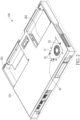
FIG. 1 is a schematic perspective view of a waterproof electronic device according to the present disclosure; -
FIG. 2 is a schematic bottom perspective view of the waterproof electronic device according to the present disclosure; -
FIG. 3 is a partial schematic exploded view of the waterproof electronic device and a fan device according to the present disclosure; -
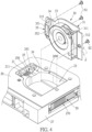
FIG. 4 is another partial schematic exploded view of the waterproof electronic device and the fan device according to the present disclosure; -
FIG. 5 is a schematic exploded view of the fan device according to the present disclosure; -
FIG. 6 is another schematic exploded view of the fan device according to the present disclosure; -
FIG. 7 is a partial cross-sectional perspective view of the waterproof electronic device according to the present disclosure; and -
FIG. 8 is a partial cross-sectional view of the waterproof electronic device according to the present disclosure. - The present disclosure is more particularly described in the following examples that are intended as illustrative only since numerous modifications and variations therein will be apparent to those skilled in the art. Like numbers in the drawings indicate like components throughout the views. As used in the description herein and throughout the claims that follow, unless the context clearly dictates otherwise, the meaning of "a", "an", and "the" includes plural reference, and the meaning of "in" includes "in" and "on". Titles or subtitles can be used herein for the convenience of a reader, which shall have no influence on the scope of the present disclosure.
- The terms used herein generally have their ordinary meanings in the art. In the case of conflict, the present document, including any definitions given herein, will prevail. The same thing can be expressed in more than one way. Alternative language and synonyms can be used for any term(s) discussed herein, and no special significance is to be placed upon whether a term is elaborated or discussed herein. A recital of one or more synonyms does not exclude the use of other synonyms. The use of examples anywhere in this specification including examples of any terms is illustrative only, and in no way limits the scope and meaning of the present disclosure or of any exemplified term. Likewise, the present disclosure is not limited to various embodiments given herein. Numbering terms such as "first", "second" or "third" can be used to describe various components, signals or the like, which are for distinguishing one component/signal from another one only, and are not intended to, nor should be construed to impose any substantive limitations on the components, signals or the like.
- Referring to
FIG. 1 to FIG. 2 , the present disclosure provides a waterproofelectronic device 100. For example, said electronic device can be applied to a waterproof laptop computer, and more particularly to an industrial laptop computer. As shown inFIG. 1 , the waterproofelectronic device 100 includes a devicemain body 101 and adisplay screen 102. For convenience of illustration, a keyboard and an outer casing are not shown inFIG. 1 . Thedisplay screen 102 is rotatably connected to one side of the devicemain body 101. However, the present disclosure is not limited thereto. For example, said electronic device can also be applied to a tablet computer or other electronic devices having a waterproof function (which are not necessarily equipped with a monitor). - In this embodiment, an electronic component that has a good waterproof performance is disposed in the waterproof
electronic device 100, and can prevent liquid or dust from entering into the devicemain body 101. More importantly, the electronic component is replaceable. Specifically, the electronic component is exemplified as a fan device at a back side of a laptop computer. - Reference is made to
FIG. 2 to FIG. 4 . The waterproofelectronic device 100 includes ahousing 20, asystem component region 20S, awaterproof wall 20W, and afan device 30. Thehousing 20 is hollow, and the material of thehousing 20 can be metal. A keyboard (not shown) and a touch pad (not shown) can be disposed on a top surface of thehousing 20. As shown inFIG. 2 , at least one receiving area (201, 202) is formed on a lower surface of thehousing 20 for accommodating, for example, a battery. Thesystem component region 20S is formed inside thehousing 20 for receiving electronic elements (e.g., a main circuit board, not shown). Thewaterproof wall 20W is concaved from a back surface of thehousing 20, and is integrally formed with thehousing 20. Thewaterproof wall 20W corresponds in shape to thefan device 30. In this embodiment, thewaterproof wall 20W does not occupy a peripheral space of the devicemain body 101 of the laptop computer, such that other input/output ports can be flexibly arranged in the peripheral space. - The
system component region 20S includes a first connectingdevice 21 exposed to thehousing 20. The first connectingdevice 21 can be referred to as a system-end connecting device. The first connectingdevice 21 has one end that is internally connected to the main circuit board (not shown), and has another end that is externally and electrically connected to thefan device 30. - The
waterproof wall 20W is disposed between thehousing 20 and thesystem component region 20S, and is concaved in thehousing 20 in an integral manner. Thewaterproof wall 20W is formed with afan receiving area 23, awire passing area 24, and anopening 250 exposed to thehousing 20. Thewire passing area 24 is located between thefan receiving area 23 and theopening 250. Theopening 250 is corresponded in position to the first connectingdevice 21. Thefan receiving area 23 is used to receive thefan device 30. - Referring to
FIG. 4 to FIG. 6 , thefan device 30 includes afan lid 31, afan body 33, acable 34, and a second connectingdevice 35. Thefan lid 31 is fixed to thewaterproof wall 20W, covers thefan receiving area 23, and extends to theopening 250. Specifically, thefan lid 31 is fastened to thewaterproof wall 20W (as shown inFIG. 2 ) by fixing members S1, S2. The fixing member can be, for example, screws. In this embodiment, an airflow enters into thefan body 33 from thefan lid 31. Thefan body 33 is fixed at one end of thefan lid 31. Thecable 34 is connected to thefan body 33 and the second connectingdevice 35, and passes through thewire passing area 24. The second connectingdevice 35 can be referred to as a fan-end connecting device. The second connectingdevice 35 is disposed on another end of thefan lid 31. Specifically, the second connectingdevice 35 is located on a bottom surface of thefan lid 31 and at one side of thefan body 33. Preferably, the second connectingdevice 35 of thefan device 30 can be coupled to the first connectingdevice 21 in a sealed manner. - As shown in
FIG. 4 , in this embodiment, thewaterproof wall 20W is further formed with aconnector receiving area 25. Theconnector receiving area 25 has a cube shape and is slightly concaved, and corresponds in shape and position to the second connectingdevice 35 of thefan device 30. Theopening 250 is formed on a bottom of theconnector receiving area 25, so that the first connectingdevice 21 is exposed. Thewire passing area 24 protrudes slightly between thefan receiving area 23 and theconnector receiving area 25. Thewire passing area 24 is formed with asurface 243. Thesurface 243 is lower than an outer surface of thewaterproof wall 20W, and can receive thecable 34 of thefan device 30. Thesurface 243 can be a curved surface or a polygon surface. In other words, in this embodiment, thecable 34 is disposed above thesurface 243 of thewire passing area 24 and is connected to thefan device 30. Thecable 34 does not penetrate through thewaterproof wall 20W. - The
housing 20 has aside wall 27. Theside wall 27 is formed with afan vent 270. An air-outlet direction F of thefan device 30 is toward thefan vent 270. The waterproofelectronic device 100 further includes a heat-dissipatingfin assembly 50. The heat-dissipatingfin assembly 50 is disposed between thefan body 33 and thefan vent 270. The heat-dissipatingfin assembly 50 is disposed under thewaterproof wall 20W. - As shown in
FIG. 1 , aheat pipe 70 of the waterproofelectronic device 100 is disposed on a top surface of thehousing 20, and is opposite to thefan device 30. One end of theheat pipe 70 contacts a heat-generating element (which is usually a central processing unit, not shown). Another end of theheat pipe 70, which is a heat-dissipating end, extends to contact the heat-dissipatingfin assembly 50 for outward dissipation of the redundant heat. Theheat pipe 70 is separated from thefan device 30, such that the waterproof performance can be improved without affecting dismount and assembly of thefan device 30. - Referring to
FIG .4 andFIG. 5 , thefan lid 31 includes amain cover 311, and an embeddedboard 312. In this embodiment, the embeddedboard 312 is slightly lower than themain cover 311 and parallel to themain cover 311. Themain cover 311 is formed with anair intake 310, and theair intake 310 corresponds in position to thefan body 33. The embeddedboard 312 is extended outward from a bottom of one side of themain cover 311. An outer surface of themain cover 311 is flush with the outer surface of thewaterproof wall 20W. The embeddedboard 312 is lower than themain cover 311, and is inserted between thewaterproof wall 20W and the heat-dissipating fin assembly 50 (as shown inFIG. 7 andFIG. 8 ). The embeddedboard 312 can be fastened to thehousing 20 by the screw S2 (as shown inFIG. 3 andFIG. 4 ). - Referring to
FIG. 5 , in this embodiment, thefan lid 31 further includes aprotective shell 315. Theprotective shell 315 is formed on the bottom surface of thefan lid 31 and located at one side of thefan body 33. As shown inFIG. 5 , theprotective shell 315 has a rectangular shape formed by four walls and is not completely closed, and an opening thereof is away from thefan lid 31. The second connectingdevice 35 is received in theprotective shell 315. Theprotective shell 315 is oriented toward the first connecting device 21 (as shown inFIG. 4 ). Appearance-wise, theprotective shell 315 of thefan lid 31 corresponds to theconnector receiving area 25 of thewaterproof wall 20W. - One side of the
protective shell 315 has agasket hole 3150 and a cablewaterproof ring 3152. The cablewaterproof ring 3152 is disposed around thegasket hole 3150. Thecable 34 of thefan device 30 passes through acable hole 3153 of the cablewaterproof ring 3152. The function of the cablewaterproof ring 3152 is that, even if liquid or dust accidentally enters thefan lid 31, the cablewaterproof ring 3152 can block the liquid or the dust from entering the protective shell 315 (i.e., from entering the second connectingdevice 35 of the fan device 30). - Referring to
FIG. 4 ,FIG. 7 andFIG. 8 , in this embodiment, the first connectingdevice 21 has a plurality ofelastic contacts 211. Theelastic contacts 211 can be, for example, pogo pins. However, the present disclosure is not limited thereto. Theelastic contacts 211 are oriented toward the second connectingdevice 35. Correspondingly, the second connectingdevice 35 includes acircuit board 351, and thecircuit board 351 is fastened in theprotective shell 315 by a screw (not shown). One surface of thecircuit board 351 has a plurality ofcontact pads 352 formed thereon. Theelastic contacts 211 correspondingly contact thecontact pads 352. - Referring to
FIG. 5 andFIG. 6 , the second connectingdevice 35 further includes acable connector 353. Thecable connector 353 is disposed on another surface of thecircuit board 351, which is opposite to thecontact pads 352. Thecable connector 353 and thecontact pads 352 are disposed on two opposite sides of thecircuit board 351. Thecable 34 is connected to thecable connector 353, and is externally connected to thefan device 30. An electrical connection sequence is arranged in the following order. Thecontact pads 352 are connected to thecable connector 353 through thecircuit board 351. Then, thecable connector 353 is connected to thefan body 33 of thefan device 30 by thecable 34. Thecable 34 passes through the cablewaterproof ring 3152, and penetrates through thegasket hole 3150 of theprotective shell 315. - Referring to
FIG. 7 andFIG. 8 , thefan device 30 can further include a first waterproof ring R1. The first waterproof ring R1 is disposed on a periphery of thefan body 33. Specifically, the first waterproof ring R1 can be configured to surround a periphery of theprotective shell 315, a periphery of an inner surface of themain cover 311, and a corner between themain cover 311 and the embeddedboard 312. The first waterproof ring R1 can be strip-shaped and closed for serving as a first waterproof line, so as to enhance the waterproof performance of this embodiment. - In addition, the
fan device 30 further includes a second waterproof ring R2. The second waterproof ring R2 is disposed between the first connectingdevice 21 and the second connectingdevice 35. Specifically, the second waterproof ring R2 is disposed on a bottom surface of theconnector receiving area 25, and surrounds theopening 250. An edge of theprotective shell 315 is in contact with the second waterproof ring R2. The second waterproof ring R2 can be formed to have a flat and rectangular shape, so that the second connectingdevice 35 can be coupled to the first connectingdevice 21 in a sealed manner. - As shown in
FIG. 7 andFIG. 8 , there are three protective lines between the second connectingdevice 35 and the first connectingdevice 21, which are the first waterproof ring R1, the second waterproof ring R2, and the cablewaterproof ring 3152. In particular, the second waterproof ring R2 is disposed between the edge of theprotective shell 315 and the bottom surface of theconnector receiving area 25, and can provide a good waterproof function. In addition to a good waterproof function between the second connectingdevice 35 and the first connectingdevice 21 of the present disclosure, thefan device 30 can be replaceable in this embodiment due to the second connectingdevice 35 being detachably connected to the first connectingdevice 21. If thefan device 30 malfunctions, a user can easily dismount thefan device 30 from thewaterproof wall 20W of the waterproofelectronic device 100 by removing screws (S 1, S2, as shown inFIG. 2 ) on thefan lid 31. Maintenance of thefan device 30 of this embodiment is convenient. - In conclusion, at least one of the effects in the waterproof electronic device and the fan device thereof provided by the present disclosure, the
fan device 30 provides the fan-end connecting device (or referred to as the second connecting device 35) that is pluggable. The second connectingdevice 35 is connected to the first connectingdevice 21 in a pluggable manner, so that thefan device 30 can be disposed in a replaceable manner in the waterproofelectronic device 100. - In addition, by virtue of "a waterproof wall being disposed between the housing and the system component region," "a fan receiving area, a wire passing area, and an opening exposed to the housing being defined by the waterproof wall," and "the cable being connected to the fan body and the second connecting device and passing through the wire passing area, and the second connecting device being coupled to the first connecting device," the waterproof performance of the waterproof electronic device can be enhanced.
- The foregoing description of the exemplary embodiments of the disclosure has been presented only for the purposes of illustration and description and is not intended to be exhaustive or to limit the disclosure to the precise forms disclosed. Many modifications and variations are possible in light of the above teaching.
- The embodiments were chosen and described in order to explain the principles of the disclosure and their practical application so as to enable others skilled in the art to utilize the disclosure and various embodiments and with various modifications as are suited to the particular use contemplated. Alternative embodiments will become apparent to those skilled in the art to which the present disclosure pertains without departing from its spirit and scope.
Claims (15)
- A fan device (30), characterized in that comprising:a fan lid (31);a fan body (33), fixed to one end of the fan lid (31);a fan-end connecting device (35), disposed at another end of the fan lid (31); anda cable (34), connected to the fan body (33) and the fan-end connecting device (35).
- The fan device according to claim 1, wherein the fan device (30) further includes a first waterproof ring (R1), and the first waterproof ring (R1) is disposed on a periphery of the fan body (33).
- The fan device according to claim 1, wherein the fan lid (31) includes a main cover (311) and an embedded board (312), an air intake (310) is formed on the main cover (311), the air intake (310) corresponds in position to the fan body (33), the embedded board (312) extends outward from a bottom of one side of the main cover (311), and the embedded board (312) is lower than the main cover (311).
- The fan device according to claim 3, wherein the fan lid (31) further includes a protective shell (315), the protective shell (315) is formed on a bottom surface of the fan lid (31), the fan-end connecting device (35) is received in the protective shell (315), and the protective shell (315) has an opening away from the fan lid (31); wherein the protective shell (315) has a gasket hole (3150) and a cable waterproof ring (3152), the cable waterproof ring (3152) is disposed around the gasket hole (3150), and the cable (34) passes through the cable waterproof ring (3152).
- The fan device according to claim 4, wherein the fan-end connecting device (35) includes a circuit board (351), and a plurality of contact pads (352) are disposed on one surface of the circuit board (351).
- The fan device according to claim 5, wherein the fan-end connecting device (35) further includes a cable connector (353), the cable connector (353) is disposed on another surface of the circuit board (351), and the cable (34) is connected to the cable connector (353).
- The fan device according to claim 4, wherein the fan device (30) further includes a second waterproof ring (R2), and the second waterproof ring (R2) is disposed on an edge of the protective shell (315).
- A waterproof electronic device (100), characterized in that comprising:a housing (20);a system component region (20S), including a first connecting device (21) exposed to the housing (20);a waterproof wall (20W), disposed between the housing (20) and the system component region (20S), wherein a fan receiving area (23), a wire passing area (24) and an opening (250) exposed to the housing (20) are defined by the waterproof wall (20W), the wire passing area (24) is arranged between the fan receiving area (23) and the opening (250), and the opening (250) corresponds in position to the first connecting device (21); anda fan device (30), as claimed in any one of the preceding claims, wherein the fan lid (31) is fixed to the waterproof wall (20W), covers the fan receiving area (23), and extends to the opening (250); wherein the fan body (33) is disposed in the fan receiving area (23); wherein the cable (34) is connected to the fan body (33) and the fan-end connecting device (35) and passes through the wire passing area (24), and the fan-end connecting device (35) is coupled to the first connecting device (21).
- The waterproof electronic device (100) according to claim 8, wherein a connector receiving area (25) is further defined by the waterproof wall (20W), the opening (250) is formed at a bottom of the connector receiving area (25), the wire passing area (24) protrudes between the fan receiving area (23) and the connector receiving area (25), the wire passing area (24) is formed to have a concave surface, and the surface is lower than an outer surface of the waterproof wall (20W).
- The waterproof electronic device (100) according to claim 8, wherein the housing (20) has a side wall (27), a fan vent (270) is formed on the side wall (27), and an air-outlet direction of the fan device (30) is toward the fan vent (270).
- The waterproof electronic device (100) according to claim 8, further comprising a heat-dissipating fin assembly (50), wherein the heat-dissipating fin assembly (50) is disposed between the fan body (33) and the fan vent (270), and the heat-dissipating fin assembly (50) is disposed under the waterproof wall (20W).
- The waterproof electronic device (100) according to claim 11, wherein an outer surface of the main cover (311) is flush with an outer surface of the waterproof wall (20W), the embedded board (312) is lower than the main cover (311), and the embedded board (312) is inserted between the waterproof wall (20W) and the heat-dissipating fin assembly (50).
- The waterproof electronic device (100) according to claim 8, wherein the first connecting device (21) includes a plurality of elastic contacts (211), the elastic contacts (211) are oriented toward the fan-end connecting device (35) and the elastic contacts (211) correspondingly contact the contact pads (352) of the fan-end connecting device (35).
- The waterproof electronic device (100) according to claim 10, wherein the second waterproof ring (R2) is disposed between the first connecting device (21) and the fan-end connecting device (35).
- A waterproof electronic device (100), characterized in that comprising:a housing (20);a system component region (20S), including a first connecting device (21) exposed to the housing (20);a waterproof wall (20W), disposed between the housing (20) and the system component region (20S), wherein a fan receiving area (23), a wire passing area (24) and an opening (250) exposed to the housing (20) are defined by the waterproof wall (20W), the wire passing area (24) is arranged between the fan receiving area (23) and the opening (250), and the opening (250) corresponds in position to the first connecting device (21); anda fan device (30), including a fan lid (31), a fan body (33), a cable (34), and a second connecting device (35), wherein the fan lid (31) is fixed to the waterproof wall (20W), covers the fan receiving area (23), and extends to the opening (250); wherein the fan body (33) is disposed in the fan receiving area (23); wherein the cable (34) is connected to the fan body (33) and the second connecting device (35) and passes through the wire passing area (24), and the second connecting device (35) is coupled to the first connecting device (21).
Applications Claiming Priority (2)
| Application Number | Priority Date | Filing Date | Title |
|---|---|---|---|
| US202263350914P | 2022-06-10 | 2022-06-10 | |
| CN202211461703.5A CN117222173A (en) | 2022-06-10 | 2022-11-17 | Waterproof electronic device and its fan device |
Publications (3)
| Publication Number | Publication Date |
|---|---|
| EP4299914A2 true EP4299914A2 (en) | 2024-01-03 |
| EP4299914A3 EP4299914A3 (en) | 2024-02-28 |
| EP4299914B1 EP4299914B1 (en) | 2026-01-14 |
Family
ID=85251912
Family Applications (1)
| Application Number | Title | Priority Date | Filing Date |
|---|---|---|---|
| EP23156787.6A Active EP4299914B1 (en) | 2022-06-10 | 2023-02-15 | Waterproof electronic device and fan device thereof |
Country Status (3)
| Country | Link |
|---|---|
| US (2) | US12399539B2 (en) |
| EP (1) | EP4299914B1 (en) |
| AU (1) | AU2023200811B2 (en) |
Families Citing this family (2)
| Publication number | Priority date | Publication date | Assignee | Title |
|---|---|---|---|---|
| WO2023058442A1 (en) * | 2021-10-07 | 2023-04-13 | 日立Astemo株式会社 | Electronic control device |
| TWI831173B (en) * | 2022-04-06 | 2024-02-01 | 奇鋐科技股份有限公司 | Fan electrical connection structure |
Citations (2)
| Publication number | Priority date | Publication date | Assignee | Title |
|---|---|---|---|---|
| US20070121292A1 (en) * | 2005-11-30 | 2007-05-31 | Kabushiki Kaisha Toshiba | Electronic apparatus |
| CN104808743B (en) * | 2014-01-24 | 2019-01-15 | 神讯电脑(昆山)有限公司 | Water proof type laptop |
Family Cites Families (24)
| Publication number | Priority date | Publication date | Assignee | Title |
|---|---|---|---|---|
| TW453470U (en) | 1999-11-11 | 2001-09-01 | Alpha Top Corp | Heat dissipation structure |
| US7158376B2 (en) * | 2001-11-19 | 2007-01-02 | Otter Products, Llc | Protective enclosure for an interactive flat-panel controlled device |
| US7054155B1 (en) | 2003-03-17 | 2006-05-30 | Unisys Corporation | Fan tray assembly |
| US6999313B2 (en) | 2003-04-22 | 2006-02-14 | Epserv Tech Corporation | Signal connection assembly of cooling module |
| WO2004100262A1 (en) | 2003-05-07 | 2004-11-18 | Fujitsu Limited | Cooling part, substrate, and electronic equipment |
| JP4167700B2 (en) | 2006-05-31 | 2008-10-15 | 株式会社東芝 | Electronics |
| TWI306188B (en) * | 2006-08-01 | 2009-02-11 | Compal Electronics Inc | Waterproof thermal management module and portable electronic apparatus using the same |
| TWI366089B (en) * | 2009-06-04 | 2012-06-11 | Pegatron Corp | Industrial computer |
| TWI357556B (en) * | 2009-06-04 | 2012-02-01 | Pegatron Corp | Industrial computer |
| US8699216B2 (en) | 2010-10-22 | 2014-04-15 | Xplore Technologies Corp. | Computer with door-mounted electronics |
| US8759721B1 (en) * | 2010-11-02 | 2014-06-24 | Piatto Technologies, Inc. | Heated or cooled dishwasher safe dishware and drinkware |
| TWI471084B (en) * | 2012-02-21 | 2015-01-21 | 緯創資通股份有限公司 | Heat dissipating mechanism suitable for electronic device and electronic device thereof |
| DE102014002452A1 (en) | 2013-03-12 | 2014-09-18 | Sew-Eurodrive Gmbh & Co Kg | Electric device with housing |
| CN104847680B (en) | 2014-02-14 | 2018-01-26 | 神讯电脑(昆山)有限公司 | fan unit |
| KR102198792B1 (en) * | 2014-03-07 | 2021-01-06 | 삼성전자주식회사 | Water Proof Electronic Device |
| TWM504440U (en) | 2015-03-13 | 2015-07-01 | Cooler Master Co Ltd | Portable electronic device and detachable auxiliary heat dissipation module thereof |
| JP2018206958A (en) | 2017-06-05 | 2018-12-27 | 株式会社デンソー | Electronic equipment |
| US11294425B2 (en) * | 2019-08-20 | 2022-04-05 | Getac Technology Corporation | Portable electronic device |
| US11301003B2 (en) * | 2019-09-24 | 2022-04-12 | Getac Technology Corporation | Eletronic device with anti-shock function |
| US11916277B2 (en) * | 2020-06-25 | 2024-02-27 | Getac Holdings Corporation | Electronic device and antenna assembly |
| CN114167945B (en) | 2020-09-11 | 2025-01-14 | 神讯电脑(昆山)有限公司 | Expanding electronic devices and electronic systems |
| CN114253352B (en) * | 2020-09-23 | 2025-08-12 | 神讯电脑(昆山)有限公司 | Door cover structure of mobile device |
| US11848502B2 (en) * | 2020-12-23 | 2023-12-19 | Getac Holdings Corporation | Electronic device |
| CN216217932U (en) | 2021-09-26 | 2022-04-05 | 珠海灿源电子科技有限公司 | Waterproof power adapter |
-
2023
- 2023-02-05 US US18/164,601 patent/US12399539B2/en active Active
- 2023-02-14 AU AU2023200811A patent/AU2023200811B2/en active Active
- 2023-02-15 EP EP23156787.6A patent/EP4299914B1/en active Active
-
2025
- 2025-05-15 US US19/208,810 patent/US20250271906A1/en active Pending
Patent Citations (2)
| Publication number | Priority date | Publication date | Assignee | Title |
|---|---|---|---|---|
| US20070121292A1 (en) * | 2005-11-30 | 2007-05-31 | Kabushiki Kaisha Toshiba | Electronic apparatus |
| CN104808743B (en) * | 2014-01-24 | 2019-01-15 | 神讯电脑(昆山)有限公司 | Water proof type laptop |
Also Published As
| Publication number | Publication date |
|---|---|
| US12399539B2 (en) | 2025-08-26 |
| EP4299914B1 (en) | 2026-01-14 |
| AU2023200811B2 (en) | 2024-06-20 |
| AU2023200811A1 (en) | 2024-01-18 |
| US20250271906A1 (en) | 2025-08-28 |
| US20230400891A1 (en) | 2023-12-14 |
| EP4299914A3 (en) | 2024-02-28 |
Similar Documents
| Publication | Publication Date | Title |
|---|---|---|
| US20250271906A1 (en) | Fan device of waterproof electronic device | |
| EP0834795B1 (en) | Mechanical structure of information processing device | |
| US10354356B2 (en) | Systems and methods for interconnecting and cooling multiple graphics processing unit (GPU) cards | |
| US6229695B1 (en) | Palm-sized computer with a frame to hold device plates | |
| US5422784A (en) | Housing arrangement for a data processing apparatus having a removably mounted circuit board above an opening in a top shell | |
| CN211928482U (en) | Electronic device | |
| US5193051A (en) | Sliding box type pen base computer with LCD and mother board in a base and with battery, power supply, and disk drives in a sliding box | |
| US20090195979A1 (en) | Electronic device with fans | |
| US20060002061A1 (en) | Motherboard adapted to a notebook computer | |
| US20060002065A1 (en) | Notebook computer with an easily disassembled main board | |
| EP1621967A1 (en) | Notebook computer with an easily disassembled main board | |
| US20230014167A1 (en) | Thermal heatsink systems and methods in information handling systems | |
| US7177147B2 (en) | Heat dissipation device for computer hard drive | |
| CN217656174U (en) | Docking station | |
| CN116561830A (en) | Electronic equipment | |
| CN211928483U (en) | Electronic device | |
| US9125324B2 (en) | Motherboard | |
| TWI821022B (en) | Water-proofing electronic device and fan device thereof | |
| TWI810049B (en) | Server and storage module | |
| CN104808743A (en) | Waterproof notebook computer | |
| CN219246005U (en) | Folding electronic device | |
| TWI687796B (en) | Portable electronic apparatus with a main body module and related expansion module | |
| CN212588695U (en) | Industrial control integrated machine without fan | |
| KR100247512B1 (en) | Computer system | |
| CN114167945A (en) | Extended electronic device and electronic system |
Legal Events
| Date | Code | Title | Description |
|---|---|---|---|
| PUAI | Public reference made under article 153(3) epc to a published international application that has entered the european phase |
Free format text: ORIGINAL CODE: 0009012 |
|
| STAA | Information on the status of an ep patent application or granted ep patent |
Free format text: STATUS: THE APPLICATION HAS BEEN PUBLISHED |
|
| AK | Designated contracting states |
Kind code of ref document: A2 Designated state(s): AL AT BE BG CH CY CZ DE DK EE ES FI FR GB GR HR HU IE IS IT LI LT LU LV MC ME MK MT NL NO PL PT RO RS SE SI SK SM TR |
|
| PUAL | Search report despatched |
Free format text: ORIGINAL CODE: 0009013 |
|
| AK | Designated contracting states |
Kind code of ref document: A3 Designated state(s): AL AT BE BG CH CY CZ DE DK EE ES FI FR GB GR HR HU IE IS IT LI LT LU LV MC ME MK MT NL NO PL PT RO RS SE SI SK SM TR |
|
| RIC1 | Information provided on ipc code assigned before grant |
Ipc: H05K 7/20 20060101ALI20240124BHEP Ipc: F04D 29/70 20060101ALI20240124BHEP Ipc: F04D 29/60 20060101ALI20240124BHEP Ipc: F04D 29/08 20060101ALI20240124BHEP Ipc: F04D 25/06 20060101ALI20240124BHEP Ipc: F04D 17/16 20060101AFI20240124BHEP |
|
| STAA | Information on the status of an ep patent application or granted ep patent |
Free format text: STATUS: REQUEST FOR EXAMINATION WAS MADE |
|
| 17P | Request for examination filed |
Effective date: 20240314 |
|
| RBV | Designated contracting states (corrected) |
Designated state(s): AL AT BE BG CH CY CZ DE DK EE ES FI FR GB GR HR HU IE IS IT LI LT LU LV MC ME MK MT NL NO PL PT RO RS SE SI SK SM TR |
|
| GRAP | Despatch of communication of intention to grant a patent |
Free format text: ORIGINAL CODE: EPIDOSNIGR1 |
|
| STAA | Information on the status of an ep patent application or granted ep patent |
Free format text: STATUS: GRANT OF PATENT IS INTENDED |
|
| INTG | Intention to grant announced |
Effective date: 20250922 |
|
| GRAS | Grant fee paid |
Free format text: ORIGINAL CODE: EPIDOSNIGR3 |
|
| GRAA | (expected) grant |
Free format text: ORIGINAL CODE: 0009210 |
|
| STAA | Information on the status of an ep patent application or granted ep patent |
Free format text: STATUS: THE PATENT HAS BEEN GRANTED |
|
| AK | Designated contracting states |
Kind code of ref document: B1 Designated state(s): AL AT BE BG CH CY CZ DE DK EE ES FI FR GB GR HR HU IE IS IT LI LT LU LV MC ME MK MT NL NO PL PT RO RS SE SI SK SM TR |
|
| REG | Reference to a national code |
Ref country code: CH Ref legal event code: F10 Free format text: ST27 STATUS EVENT CODE: U-0-0-F10-F00 (AS PROVIDED BY THE NATIONAL OFFICE) Effective date: 20260114 Ref country code: GB Ref legal event code: FG4D |
|
| REG | Reference to a national code |
Ref country code: DE Ref legal event code: R096 Ref document number: 602023010580 Country of ref document: DE |
|
| REG | Reference to a national code |
Ref country code: IE Ref legal event code: FG4D |
|
| PGFP | Annual fee paid to national office [announced via postgrant information from national office to epo] |
Ref country code: DE Payment date: 20260129 Year of fee payment: 4 |
|
| PGFP | Annual fee paid to national office [announced via postgrant information from national office to epo] |
Ref country code: AT Payment date: 20260301 Year of fee payment: 4 |
|
| PGFP | Annual fee paid to national office [announced via postgrant information from national office to epo] |
Ref country code: IT Payment date: 20260228 Year of fee payment: 4 |
|
| PGFP | Annual fee paid to national office [announced via postgrant information from national office to epo] |
Ref country code: FR Payment date: 20260212 Year of fee payment: 4 |