EP4299880A1 - Probe heat shielding - Google Patents
Probe heat shielding Download PDFInfo
- Publication number
- EP4299880A1 EP4299880A1 EP23182892.2A EP23182892A EP4299880A1 EP 4299880 A1 EP4299880 A1 EP 4299880A1 EP 23182892 A EP23182892 A EP 23182892A EP 4299880 A1 EP4299880 A1 EP 4299880A1
- Authority
- EP
- European Patent Office
- Prior art keywords
- probe
- sleeve
- boss
- gas turbine
- turbine engine
- Prior art date
- Legal status (The legal status is an assumption and is not a legal conclusion. Google has not performed a legal analysis and makes no representation as to the accuracy of the status listed.)
- Pending
Links
Images

Classifications
-
- F—MECHANICAL ENGINEERING; LIGHTING; HEATING; WEAPONS; BLASTING
- F02—COMBUSTION ENGINES; HOT-GAS OR COMBUSTION-PRODUCT ENGINE PLANTS
- F02C—GAS-TURBINE PLANTS; AIR INTAKES FOR JET-PROPULSION PLANTS; CONTROLLING FUEL SUPPLY IN AIR-BREATHING JET-PROPULSION PLANTS
- F02C7/00—Features, components parts, details or accessories, not provided for in, or of interest apart form groups F02C1/00 - F02C6/00; Air intakes for jet-propulsion plants
- F02C7/24—Heat or noise insulation
-
- F—MECHANICAL ENGINEERING; LIGHTING; HEATING; WEAPONS; BLASTING
- F01—MACHINES OR ENGINES IN GENERAL; ENGINE PLANTS IN GENERAL; STEAM ENGINES
- F01D—NON-POSITIVE DISPLACEMENT MACHINES OR ENGINES, e.g. STEAM TURBINES
- F01D25/00—Component parts, details, or accessories, not provided for in, or of interest apart from, other groups
- F01D25/08—Cooling; Heating; Heat-insulation
- F01D25/14—Casings modified therefor
-
- F—MECHANICAL ENGINEERING; LIGHTING; HEATING; WEAPONS; BLASTING
- F01—MACHINES OR ENGINES IN GENERAL; ENGINE PLANTS IN GENERAL; STEAM ENGINES
- F01D—NON-POSITIVE DISPLACEMENT MACHINES OR ENGINES, e.g. STEAM TURBINES
- F01D17/00—Regulating or controlling by varying flow
- F01D17/02—Arrangement of sensing elements
-
- F—MECHANICAL ENGINEERING; LIGHTING; HEATING; WEAPONS; BLASTING
- F01—MACHINES OR ENGINES IN GENERAL; ENGINE PLANTS IN GENERAL; STEAM ENGINES
- F01D—NON-POSITIVE DISPLACEMENT MACHINES OR ENGINES, e.g. STEAM TURBINES
- F01D21/00—Shutting-down of machines or engines, e.g. in emergency; Regulating, controlling, or safety means not otherwise provided for
- F01D21/003—Arrangements for testing or measuring
-
- F—MECHANICAL ENGINEERING; LIGHTING; HEATING; WEAPONS; BLASTING
- F01—MACHINES OR ENGINES IN GENERAL; ENGINE PLANTS IN GENERAL; STEAM ENGINES
- F01D—NON-POSITIVE DISPLACEMENT MACHINES OR ENGINES, e.g. STEAM TURBINES
- F01D25/00—Component parts, details, or accessories, not provided for in, or of interest apart from, other groups
- F01D25/28—Supporting or mounting arrangements, e.g. for turbine casing
-
- F—MECHANICAL ENGINEERING; LIGHTING; HEATING; WEAPONS; BLASTING
- F01—MACHINES OR ENGINES IN GENERAL; ENGINE PLANTS IN GENERAL; STEAM ENGINES
- F01D—NON-POSITIVE DISPLACEMENT MACHINES OR ENGINES, e.g. STEAM TURBINES
- F01D25/00—Component parts, details, or accessories, not provided for in, or of interest apart from, other groups
- F01D25/28—Supporting or mounting arrangements, e.g. for turbine casing
- F01D25/285—Temporary support structures, e.g. for testing, assembling, installing, repairing; Assembly methods using such structures
-
- F—MECHANICAL ENGINEERING; LIGHTING; HEATING; WEAPONS; BLASTING
- F02—COMBUSTION ENGINES; HOT-GAS OR COMBUSTION-PRODUCT ENGINE PLANTS
- F02C—GAS-TURBINE PLANTS; AIR INTAKES FOR JET-PROPULSION PLANTS; CONTROLLING FUEL SUPPLY IN AIR-BREATHING JET-PROPULSION PLANTS
- F02C3/00—Gas-turbine plants characterised by the use of combustion products as the working fluid
- F02C3/04—Gas-turbine plants characterised by the use of combustion products as the working fluid having a turbine driving a compressor
-
- F—MECHANICAL ENGINEERING; LIGHTING; HEATING; WEAPONS; BLASTING
- F02—COMBUSTION ENGINES; HOT-GAS OR COMBUSTION-PRODUCT ENGINE PLANTS
- F02C—GAS-TURBINE PLANTS; AIR INTAKES FOR JET-PROPULSION PLANTS; CONTROLLING FUEL SUPPLY IN AIR-BREATHING JET-PROPULSION PLANTS
- F02C7/00—Features, components parts, details or accessories, not provided for in, or of interest apart form groups F02C1/00 - F02C6/00; Air intakes for jet-propulsion plants
- F02C7/28—Arrangement of seals
-
- G—PHYSICS
- G01—MEASURING; TESTING
- G01M—TESTING STATIC OR DYNAMIC BALANCE OF MACHINES OR STRUCTURES; TESTING OF STRUCTURES OR APPARATUS, NOT OTHERWISE PROVIDED FOR
- G01M15/00—Testing of engines
- G01M15/14—Testing gas-turbine engines or jet-propulsion engines
-
- F—MECHANICAL ENGINEERING; LIGHTING; HEATING; WEAPONS; BLASTING
- F01—MACHINES OR ENGINES IN GENERAL; ENGINE PLANTS IN GENERAL; STEAM ENGINES
- F01D—NON-POSITIVE DISPLACEMENT MACHINES OR ENGINES, e.g. STEAM TURBINES
- F01D25/00—Component parts, details, or accessories, not provided for in, or of interest apart from, other groups
- F01D25/30—Exhaust heads, chambers, or the like
-
- F—MECHANICAL ENGINEERING; LIGHTING; HEATING; WEAPONS; BLASTING
- F05—INDEXING SCHEMES RELATING TO ENGINES OR PUMPS IN VARIOUS SUBCLASSES OF CLASSES F01-F04
- F05D—INDEXING SCHEME FOR ASPECTS RELATING TO NON-POSITIVE-DISPLACEMENT MACHINES OR ENGINES, GAS-TURBINES OR JET-PROPULSION PLANTS
- F05D2220/00—Application
- F05D2220/30—Application in turbines
- F05D2220/32—Application in turbines in gas turbines
- F05D2220/323—Application in turbines in gas turbines for aircraft propulsion, e.g. jet engines
-
- F—MECHANICAL ENGINEERING; LIGHTING; HEATING; WEAPONS; BLASTING
- F05—INDEXING SCHEMES RELATING TO ENGINES OR PUMPS IN VARIOUS SUBCLASSES OF CLASSES F01-F04
- F05D—INDEXING SCHEME FOR ASPECTS RELATING TO NON-POSITIVE-DISPLACEMENT MACHINES OR ENGINES, GAS-TURBINES OR JET-PROPULSION PLANTS
- F05D2240/00—Components
- F05D2240/10—Stators
- F05D2240/15—Heat shield
-
- F—MECHANICAL ENGINEERING; LIGHTING; HEATING; WEAPONS; BLASTING
- F05—INDEXING SCHEMES RELATING TO ENGINES OR PUMPS IN VARIOUS SUBCLASSES OF CLASSES F01-F04
- F05D—INDEXING SCHEME FOR ASPECTS RELATING TO NON-POSITIVE-DISPLACEMENT MACHINES OR ENGINES, GAS-TURBINES OR JET-PROPULSION PLANTS
- F05D2240/00—Components
- F05D2240/55—Seals
-
- F—MECHANICAL ENGINEERING; LIGHTING; HEATING; WEAPONS; BLASTING
- F05—INDEXING SCHEMES RELATING TO ENGINES OR PUMPS IN VARIOUS SUBCLASSES OF CLASSES F01-F04
- F05D—INDEXING SCHEME FOR ASPECTS RELATING TO NON-POSITIVE-DISPLACEMENT MACHINES OR ENGINES, GAS-TURBINES OR JET-PROPULSION PLANTS
- F05D2260/00—Function
- F05D2260/20—Heat transfer, e.g. cooling
- F05D2260/231—Preventing heat transfer
-
- F—MECHANICAL ENGINEERING; LIGHTING; HEATING; WEAPONS; BLASTING
- F05—INDEXING SCHEMES RELATING TO ENGINES OR PUMPS IN VARIOUS SUBCLASSES OF CLASSES F01-F04
- F05D—INDEXING SCHEME FOR ASPECTS RELATING TO NON-POSITIVE-DISPLACEMENT MACHINES OR ENGINES, GAS-TURBINES OR JET-PROPULSION PLANTS
- F05D2260/00—Function
- F05D2260/30—Retaining components in desired mutual position
- F05D2260/37—Retaining components in desired mutual position by a press fit connection
-
- F—MECHANICAL ENGINEERING; LIGHTING; HEATING; WEAPONS; BLASTING
- F05—INDEXING SCHEMES RELATING TO ENGINES OR PUMPS IN VARIOUS SUBCLASSES OF CLASSES F01-F04
- F05D—INDEXING SCHEME FOR ASPECTS RELATING TO NON-POSITIVE-DISPLACEMENT MACHINES OR ENGINES, GAS-TURBINES OR JET-PROPULSION PLANTS
- F05D2260/00—Function
- F05D2260/80—Diagnostics
-
- F—MECHANICAL ENGINEERING; LIGHTING; HEATING; WEAPONS; BLASTING
- F05—INDEXING SCHEMES RELATING TO ENGINES OR PUMPS IN VARIOUS SUBCLASSES OF CLASSES F01-F04
- F05D—INDEXING SCHEME FOR ASPECTS RELATING TO NON-POSITIVE-DISPLACEMENT MACHINES OR ENGINES, GAS-TURBINES OR JET-PROPULSION PLANTS
- F05D2270/00—Control
- F05D2270/80—Devices generating input signals, e.g. transducers, sensors, cameras or strain gauges
Definitions
- the application relates generally to aircraft engines and, more particularly, to a thermal protection for a probe disposed in a hot section of the engine.
- Aircraft engines such as gas turbine engines, include sections at low temperatures, namely cold section modules, and sections at high temperatures, namely hot section modules.
- the cold section modules include for example the compressor, while the hot section modules include for example, the combustor and the turbine. While some mechanical components may sustain the high temperatures prevailing in the hot section modules, other components, such as probes, may benefit from thermal protection.
- a gas turbine engine hot section comprising: a turbine housing extending around a central axis and having a first probe boss; an exhaust case surrounding the turbine housing and having a second probe boss aligned with the first probe boss on the turbine housing, a cavity radially between the turbine housing and the exhaust case; a probe extending through the second probe boss, the cavity and the first probe boss; and a sleeve extending from the first probe boss through the cavity and into the second probe boss, the sleeve circumscribing an annular cavity around the probe, the annular cavity being sealed at opposed radially inner and radially outer ends thereof to form a dead air cavity around the probe.
- an aircraft power plant comprising: a nacelle; a gas turbine engine mounted in the nacelle, the gas turbine engine comprising: a compressor; a turbine drivingly connected to the compressor, the turbine housed in a turbine housing extending around a central axis, the turbine housing having a first probe boss; an exhaust case for discharging combustion gases received from the turbine, the exhaust case surrounding the turbine housing and having a second probe boss aligned with the first probe boss; a probe extending through the first and second probe bosses and into the turbine housing; and a sleeve projecting from the first probe boss into the second probe boss, the sleeve circumscribing an annular cavity around the probe, the annular cavity closed at both a radially outer end and a radially inner end thereof.
- a thermal shielding arrangement for a probe extending through an exhaust case and a turbine housing of an aircraft engine, the thermal shielding arrangement comprising: a sleeve having a radially inner end mounted with a tight fit engagement to the turbine housing and a radially outer end floatingly received in a probe boss on the exhaust case, the sleeve circumscribing an annular cavity around the probe, the annular cavity being closed at opposed ends thereof.
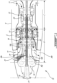
- Fig. 1 illustrates an aircraft power plant comprising a nacelle N housing a gas turbine engine 10 of a type preferably provided for use in subsonic flight, and generally comprising in serial flow communication an air inlet 11, a compressor 12 for pressurizing the air from the air inlet 11, a combustor 13 in which the compressed air is mixed with fuel and ignited for generating an annular stream of hot combustion gases, a turbine 14 for extracting energy from the combustion gases, and an exhaust case 15 through which the combustion gases exit the engine 10.
- the turbine 14 includes a low pressure (LP) or power turbine 14a drivingly connected to an input end of a fully enclosed reduction gearbox (RGB) 16.
- the RGB 16 has an output end drivingly connected to an output shaft 18 configured to drive a rotatable load (not shown).
- the rotatable load can take the form of a propeller or a rotor, such as a helicopter main rotor.
- the gas turbine engine 10 has an engine centerline 17.
- the compressor and the turbine rotors are mounted in-line for rotation about the engine centerline 17.
- the gas turbine engine 10 has an axially extending central core which defines an annular gaspath 20 through which gases flow, as depicted by flow arrows in Fig. 1 .
- the exemplary embodiment shown in Fig. 1 is a "reverse-flow" engine because gases flow through the gaspath 20 from the air inlet 11 at a rear portion thereof, to the exhaust case 15 at a front portion thereof.
- the engine 10 can have an engine architecture corresponding to that of the engine described in applicant's US Patent No. 10,393,027 issued on August 27, 2019 , the entire content of which is herein incorporated by reference. While the engine 10 is exemplified as a reverse flow engine, it is understood that the engine could be embodied as a through-flow engine.
- the exhaust case 15 may comprise an asymmetric dual port exhaust duct 30 for exhausting combustion gases received from the last stage of the LP turbine 14a on opposed sides of the engine 10.
- the dual port exhaust duct 30 is qualified as "asymmetric" because the two exhaust ports thereof are not coaxial to the engine centerline 17 (i.e. the exhaust flow discharged from the exhaust duct is not axial, it is rather discharged in a direction that diverges from the engine centerline 17).
- the dual port exhaust duct 30 has a generally "Y-shaped" annular body including an annular central inlet conduit portion extending axially around the engine centerline 17 for receiving the annular flow of combustions gases discharged from the last stage of LP turbine 14a, and first and second diverging outlet conduit portions 30b, 30c branching off laterally from the central inlet conduit portion.
- the first and second outlet conduit portions 30b, 30c are identical.
- the turbine 14 comprises a power or LP turbine housing 24 mounted to and extending axially from the RGB 16 centrally into the hollow center of the annular exhaust duct 30.
- the LP turbine housing 24 is configured to receive a bearing (not shown) for supporting the LP turbine rotor(s).
- the exhaust duct 30 is axially slid in position over the LP turbine housing 24.
- the engine 10 has a cold section C.
- the cold section C includes the air inlet 11 and the compressor 12.
- the engine 10 also has a hot section H, which in use, is subject to high temperatures.
- the hot section H includes the combustor 13, the turbine 14 and the exhaust case 15.
- the temperatures inside the turbine 14 are typically in excess of 1000 degree.
- the continuous flow of gas to which the turbine 14 is exposed can be at temperatures up to 1700 degree. C.
- the engine 10 is equipped with a plurality of probes (sensors) for measuring various operating parameters, such as torque, speed, distance, temperature, pressure etc. Some of these probes are disposed in the hot section H of the engine 10. Accordingly, these probes need to be able to cope with the high temperatures prevailing in the hot section H of the engine 10. It may thus be desirable to thermally shield the probes in order to maintain the temperature of the probes within acceptable limits.
- Figs. 1-3 illustrate an example of such a thermally shielded probe. More particularly, Figs. 1-3 illustrate a probe 22 projecting through the exhaust case 15 and the LP turbine housing 24 to a location where a tip 22a of the probe 22 is positioned adjacent to the LP turbine shaft 14b for measuring an operating parameter (e.g. speed and/or torque) of the LP turbine 14a.
- an operating parameter e.g. speed and/or torque
- the exemplary probe 22 extends through a probe boss 32 mounted in a receiving hole defined at the top dead center of the exhaust duct 30 between the two diverging outlet conduit portions 30b, 30c thereof.
- the term "boss" is herein intended to generally refer to a mounting feature on a work piece. For instance, it can take the form of a protruding feature used to locate one component (e.g. a probe) within a pocket or hole of another component (e.g. the exhaust duct).
- the probe boss 32 may be provided in the form of a cylindrical sleeve 32a cast with an outer flange 32b welded or otherwise suitably secured to the exhaust duct 30.
- the sleeve 32a has a slanted tubular portion that projects inwardly into the exhaust duct 30 in a "dead" air cavity 34 radially between the LP turbine housing 24 and the exhaust duct 30.
- the slanted tubular portion is aligned with an associated probe boss 36 provided on the turbine housing 24.
- the probe bosses 32, 36 extend centrally around a common probe axis P.
- Such axially aligned probe bosses 32, 36 provide a passage for the probe 22 through the exhaust case 15 and the turbine housing 24.
- the probe 22 extends through the registering probe bosses 32, 36 and into the LP turbine housing 24 next to the LP turbine shaft 14b.
- the tip portion 22a of the probe 22 is thermally shielded by the oil contained in the LP turbine housing 24.
- the upper portion of the probe 22 in the cavity 34 between the exhaust duct 30 and the turbine housing 24 does not benefit from the heat shielding action of the oil in the turbine housing 24.
- a probe heat shield is provided in the cavity 34 to protect the upper portion of the probe 22 from heat radiations emanating from the exhaust duct 30.
- the probe heat shield is configured to create a heat shielding volume around the probe 22 along a radial extent of the cavity 34 between the exhaust duct 30 and the LP turbine housing 24 while allowing for the assembly of the exhaust duct 30 over the LP turbine housing 24.
- the probe heat shield may include a thermal blanket 38 mounted to a radially outer surface of the turbine housing 24 so as to cap or surround the probe boss 36.
- the thermal blanket 38 can include a thermal insulation core (e.g. high temperature insulation fiber/wool materials) encapsulated in a metallic skin (e.g. sheet metal or metallic foil).
- the thermal blanket 38 forms a protective enclosure around a first portion of the length the probe projecting radially outwardly from the LP turbine probe boss 36.
- the protective enclosure formed by the thermal blanket 38 on the LP turbine housing 24 only radially extends along a portion of the cavity 34.
- the radially outer end of the thermal blanket 38 through which the probe 22 extends is spaced radially inwardly from the inner end of the probe boss 32 on the exhaust duct 30 so as to permit axial assembly of the exhaust duct 30 over the LP turbine housing 24 along the engine centerline 17.
- the heat shield further comprises a sleeve 40, which bridges the space between the LP turbine housing 24 and the exhaust case 15. As will be seen hereinafter, the sleeve 40 cooperates with sealing features and adjoining structures to create an annular "dead" air cavity 42 around the probe 22.
- the sleeve 40 has a radially inner end 40a fixedly mounted to the turbine housing 24. More particularly, the radially inner end 40a of the sleeve 40 is assembled on the probe boss 36 with a tight fit (also know as an interference fit). The radially inner end 40a of the sleeve 40 has an inner diameter surface sized for a tight fit engagement with a corresponding outer diameter surface 36a at a radially outer distal end of the probe boss 36. As shown in Fig.
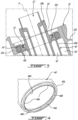
- the inner diameter surface of the sleeve 40 may include circumferentially spaced-apart tight fit contact surface segments 44a spaced by inter-segment slots 44b to provide a circumferentially discontinuous tight fit engagement of the sleeve 40 on the outer diameter surface 36a of the probe boss 36.
- Such a discontinuous or interrupted tight fit interface between the sleeve 40 and the probe boss 36 may be used to facilitate assembly and dis-assembly by reducing the assembly/dis-assembly loads required to assemble or dis-assemble the sleeve 40.
- the sleeve assembly may be further facilitated by thermally expanding the sleeve 40 prior to the sleeve 40 being engaged over the probe boss 36.
- the sleeve 40 is allowed to cool down to create the interference fit with the probe boss 36.
- the material of the sleeve 40 is selected to have substantially the same coefficient of thermal expansion as that of the probe boss 36 of the LP turbine housing 24 to preserve the integrity of the interference fit during engine operation.
- the LP turbine housing 24 and the sleeve 40 could be made from a nickel-based superalloy (e.g. Inconel 625).
- the inner diameter surface of the sleeve 40 has three tight fit contact surface segments 44a and three inter-segment slots 44b.
- the number of tight fit contact surface segments 44a and, thus, of inter-segment slots 44b can vary. For instance, only two tight fit contact surface segments 44a could be provided.
- the sleeve 40 could include more than three tight fit contact surface segments 44a.
- the tight fit contact surface segments 44a and the inter-segments slots 44b have a same circumferential length. However, it is understood that the circumferential length of the tight fit contact surface segments 44a could be different from that of the inter-segment slots 44b.
- the tight fit contact surface segments 44a are equally circumferentially distributed around the radially inner end of the sleeve 40 to provide for a uniform circumferential engagement of the sleeve 40 on the probe boss 36.
- the inter-segment slots 44b may be milled or otherwise suitably formed in the inner diameter surface of the radially inner end of the sleeve 40.
- the tight fit contact surface segments 44a could be formed by additive manufacturing or other suitable manufacturing processes.
- the probe boss 36 has an annular outer shoulder 36b projecting from the outer diameter surface 36a.
- the outer shoulder 36b provides an abutting surface (normal to the axis P) against which the radially inner end surface of the sleeve 40 is pushed in sealing abutment at assembly.
- the radially inner end 40a of the sleeve 40 can be sealingly assembled onto the probe boss 36 even though the tight fit interface between the sleeve 40 and the probe boss 36 is not circumferentially continuous.
- Such a mounting arrangement of the sleeve 40 on the probe boss 36 allows to substantially sealingly close the radially inner end of the annular cavity 42, thereby preventing hot air circulation therethrough.
- the probe boss 36 further comprises an annular inner shoulder 36c for engagement with a corresponding annular outer shoulder 22b on the probe 22.
- the probe 22 is releasably secured in position against shoulder 36c by a hollow bolt 50 threadably engageable with the probe boss 36.
- the hollow bolt 50 is adapted to be slidably fitted over the upper end portion of the probe 22 and is provided at a distal end with outer threads 50a for meshing engagement with corresponding inner threads 36d formed in an inner diameter surface of the probe boss 36 above the shoulder 36c.
- the hollow bolt 50 may have a hexagonal head 50b opposite its externally threaded end portion for facilitating tightening of the bolt 50 into the probe boss 36.
- the hollow bolt 50 has an annular outer shoulder 50c at an upper end thereof axially adjacent to the hexagonal head 50b.
- the shoulder 50c is configured to axially compress a resilient or compressible-type seal, such as the exemplified C-ring seal 52 (herein after C-seal 52), against an annular inner shoulder 40c projecting from an inner diameter surface of a radially outer end 40b of the sleeve 40.
- the C-seal 52 serves the dual purpose of: 1) sealing the radially outer end of the dead air cavity 42 and 2) urging/biasing the sleeve 40 in sealing contact against the outer shoulder 36b on the probe boss 36 while accommodating thermal growth of the sleeve 40 during engine operation.
- the sleeve 40 is thus axially clamped between the outer shoulder 50c of the bolt 50 and the outer shoulder 36b of the probe boss 36 with a spring-loaded action provided by the C-seal 52.
- the C-seal clamping assembly may be configured such that the C-seal 52 is compressed (and thus axially loads the sleeve 40) at cold assembly condition (i.e. when the sleeve 40 is not subject to thermal growth).
- the annular cavity 42 between the sleeve 40 and the hollow bolt 50 of the probe 22 is closed at both its radially inner and radially outer ends.
- the annular cavity 42 is thus a "dead" air cavity that operates as thermal insulation around the probe 22. That is a cavity in which there is no air circulation.
- a pressure delta may also be used to prevent fluid flow (e.g. hot air) from entering the dead air cavity 42.
- the compressible seal e.g. the C-seal 52
- at the radially outer end of the sleeve 40 allows to accommodate the thermal expansion of the sleeve 40 relative to the bolt 50 as schematically depicted by arrows A in Fig. 2 while preserving the integrity of the dead air cavity 42.
- the sleeve 40 extends radially into the space thermally shielded by the thermal blanket 38 around the probe boss 36.
- the radially outer end 40b of the sleeve 40 is floatingly/movably received in the second probe boss 32 (i.e. the probe boss on the exhaust duct 30) for relative movement with respect thereto in response to thermal growth.
- the radially outer end 40b of the sleeve 40 is spaced from a surrounding inner surface of the probe boss 32 by an annular control gap 60.
- a compressible seal such as a rope seal 62, extends across the annular control gap 60.
- the rope seal 62 may be removably mounted in an annular groove or any suitable seat defined in an outer diameter surface of the radially outer end 40b of the sleeve 40.
- the rope seal 62 is made out of a compressible material to provide sealing as well as damping between the sleeve 40 and the probe boss 32 of the exhaust case 15. More particularly, the rope seal 62 prevents hot air leakage from cavity 34 into the air cavity G while limiting the transmission of vibrations between the sleeve 40 and the probe boss 32. In addition, the rope seal 62 prevents water or sand/dirt particles from being ingested from cavity G into cavity 34.
- the sleeve 40 is installed in position after the exhaust case 15 and the turbine housing 24 have been assembled together.
- the sleeve 40 is first thermally expanded and then installed over the first probe boss 36 via the second probe boss 32.
- the sleeve 40 is pushed axially along axis P so as to sealingly abut the annular end face at the radially inner end 40a of the sleeve 40 against the outer shoulder 36b of the probe boss 36.
- the sleeve 40 is allowed to cool down to cause the tight fit contact surface segments 44a on the inner diameter surface of the sleeve 40 to contract against the outer diameter surface 36a of the probe boss 36, thereby providing for an interference fit between the sleeve 40 and the probe boss 36.
- the so created interference fit secures the sleeve 40 on the turbine housing 24.
- the rope seal 62 is typically installed on the sleeve 40 prior to the sleeve 40 being inserted through the probe boss 32.
- the probe 22 is inserted through the probe bosses 32, 36 and pushed axially in position so as to abut the probe outer shoulder 22b against the corresponding inner shoulder 36c of the probe boss 36.
- the C-seal 52 or an equivalent compression seal thereof is seated on the inner shoulder 40c at the radially outer end 40b of the sleeve 40.
- the hollow bolt 50 is fitted over the probe 22 and tightened to the probe boss 36 in order to secure the probe 22 in position and to apply a clamping load against the sleeve 40 via the bolt outer shoulder 50c and the C-seal 52.
- the compression of the C-seal 52 between the sleeve 40 and the hollow bolt 50 allows to seal the radially outer end of the annular dead air cavity 42.
- the radially inner end of the cavity 42 is sealed via the engagement of the end face of the radially inner end 40a of the sleeve 40 and the opposing surface of the outer shoulder 36b on the probe boss 36.
- the biasing action of the C-seal 52 on the sleeve 40 contributes to ensure proper sealing contact between the radially inner end 40a of the sleeve 40 and the outer shoulder 36b of the probe boss 36. It can be appreciated that the cavity 42 is closed at both ends thereof, thereby avoiding air recirculation or debris ingestion.
- the mounting arrangement thus provides for the creation of a dead air cavity as a means for thermally shielding the probe 22 from the heat radiated into the cavity 34 between the exhaust duct 30 and the turbine housing 24 during engine operation.
- the sleeve mounting arrangement provides a simple solution to thermally protect the probe 22 from heat radiation emanating from the exhaust duct 30.
- the bolt 50 is first untightened and removed. Thereafter, the probe 22 is removed. Then, a suitable tool, such as a puller (not shown), is used to grab the sleeve 40 by its inner shoulder 40c to pull the sleeve 40 out of engagement from the first probe boss 36.
- the inner shoulder 40c thus serves as a sealing surface and a pulling feature to remove the sleeve 40 when need be.
Landscapes
- Engineering & Computer Science (AREA)
- Mechanical Engineering (AREA)
- General Engineering & Computer Science (AREA)
- Chemical & Material Sciences (AREA)
- Combustion & Propulsion (AREA)
- Physics & Mathematics (AREA)
- General Physics & Mathematics (AREA)
- Turbine Rotor Nozzle Sealing (AREA)
- Supercharger (AREA)
Abstract
Description
- The application relates generally to aircraft engines and, more particularly, to a thermal protection for a probe disposed in a hot section of the engine.
- Aircraft engines, such as gas turbine engines, include sections at low temperatures, namely cold section modules, and sections at high temperatures, namely hot section modules. The cold section modules include for example the compressor, while the hot section modules include for example, the combustor and the turbine. While some mechanical components may sustain the high temperatures prevailing in the hot section modules, other components, such as probes, may benefit from thermal protection.
- In one aspect, there is provided a gas turbine engine hot section comprising: a turbine housing extending around a central axis and having a first probe boss; an exhaust case surrounding the turbine housing and having a second probe boss aligned with the first probe boss on the turbine housing, a cavity radially between the turbine housing and the exhaust case; a probe extending through the second probe boss, the cavity and the first probe boss; and a sleeve extending from the first probe boss through the cavity and into the second probe boss, the sleeve circumscribing an annular cavity around the probe, the annular cavity being sealed at opposed radially inner and radially outer ends thereof to form a dead air cavity around the probe.
- In another aspect, there is provided an aircraft power plant comprising: a nacelle; a gas turbine engine mounted in the nacelle, the gas turbine engine comprising: a compressor; a turbine drivingly connected to the compressor, the turbine housed in a turbine housing extending around a central axis, the turbine housing having a first probe boss; an exhaust case for discharging combustion gases received from the turbine, the exhaust case surrounding the turbine housing and having a second probe boss aligned with the first probe boss; a probe extending through the first and second probe bosses and into the turbine housing; and a sleeve projecting from the first probe boss into the second probe boss, the sleeve circumscribing an annular cavity around the probe, the annular cavity closed at both a radially outer end and a radially inner end thereof.
- In a further aspect, there is provided a thermal shielding arrangement for a probe extending through an exhaust case and a turbine housing of an aircraft engine, the thermal shielding arrangement comprising: a sleeve having a radially inner end mounted with a tight fit engagement to the turbine housing and a radially outer end floatingly received in a probe boss on the exhaust case, the sleeve circumscribing an annular cavity around the probe, the annular cavity being closed at opposed ends thereof.
- Reference is now made to the accompanying figures in which:
-
Fig. 1 is a schematic longitudinal/axial cross-section view of an exemplary boosted reverse flow gas turbine engine having a thermally shielded turbine probe; -
Fig. 2 is an enlarged cross-section view illustrating a heat shield sleeve extending around the turbine probe in a cavity between an exhaust case and a power turbine housing of the engine shown inFig. 1 ; -
Fig. 3 is a further enlarged cross-section view illustrating assembly details at a radially outer end of the heat shield sleeve; and -
Fig. 4 is an enlarged view of a radially inner end of the heat shield sleeve and illustrating circumferentially spaced-apart tight fit contact surface segments spaced by inter-slot segments. -
Fig. 1 illustrates an aircraft power plant comprising a nacelle N housing agas turbine engine 10 of a type preferably provided for use in subsonic flight, and generally comprising in serial flow communication anair inlet 11, acompressor 12 for pressurizing the air from theair inlet 11, acombustor 13 in which the compressed air is mixed with fuel and ignited for generating an annular stream of hot combustion gases, aturbine 14 for extracting energy from the combustion gases, and anexhaust case 15 through which the combustion gases exit theengine 10. Theturbine 14 includes a low pressure (LP) orpower turbine 14a drivingly connected to an input end of a fully enclosed reduction gearbox (RGB) 16. TheRGB 16 has an output end drivingly connected to anoutput shaft 18 configured to drive a rotatable load (not shown). For instance, the rotatable load can take the form of a propeller or a rotor, such as a helicopter main rotor. Thegas turbine engine 10 has anengine centerline 17. According to the illustrated embodiment, the compressor and the turbine rotors are mounted in-line for rotation about theengine centerline 17. - The
gas turbine engine 10 has an axially extending central core which defines anannular gaspath 20 through which gases flow, as depicted by flow arrows inFig. 1 . The exemplary embodiment shown inFig. 1 is a "reverse-flow" engine because gases flow through thegaspath 20 from theair inlet 11 at a rear portion thereof, to theexhaust case 15 at a front portion thereof. According to one aspect, theengine 10 can have an engine architecture corresponding to that of the engine described in applicant'sUS Patent No. 10,393,027 issued on August 27, 2019 engine 10 is exemplified as a reverse flow engine, it is understood that the engine could be embodied as a through-flow engine. - As shown in
Fig. 1 , theexhaust case 15 may comprise an asymmetric dualport exhaust duct 30 for exhausting combustion gases received from the last stage of theLP turbine 14a on opposed sides of theengine 10. The dualport exhaust duct 30 is qualified as "asymmetric" because the two exhaust ports thereof are not coaxial to the engine centerline 17 (i.e. the exhaust flow discharged from the exhaust duct is not axial, it is rather discharged in a direction that diverges from the engine centerline 17). According to at least some embodiments, the dualport exhaust duct 30 has a generally "Y-shaped" annular body including an annular central inlet conduit portion extending axially around theengine centerline 17 for receiving the annular flow of combustions gases discharged from the last stage ofLP turbine 14a, and first and second divergingoutlet conduit portions 30b, 30c branching off laterally from the central inlet conduit portion. According to some embodiments, the first and secondoutlet conduit portions 30b, 30c are identical. - Still referring to
Fig. 1 , it can be seen that theturbine 14 comprises a power orLP turbine housing 24 mounted to and extending axially from theRGB 16 centrally into the hollow center of theannular exhaust duct 30. TheLP turbine housing 24 is configured to receive a bearing (not shown) for supporting the LP turbine rotor(s). During assembly, theexhaust duct 30 is axially slid in position over theLP turbine housing 24. Once theexhaust duct 30 has been properly positioned over theLP turbine housing 24, the two are detachably secured to theRGB 16 such as by bolting at a front flange interface. - Still referring to
Fig. 1 , it can be seen that theengine 10 has a cold section C. The cold section C includes theair inlet 11 and thecompressor 12. Theengine 10 also has a hot section H, which in use, is subject to high temperatures. The hot section H includes thecombustor 13, theturbine 14 and theexhaust case 15. For instance, the temperatures inside theturbine 14 are typically in excess of 1000 degree. C. In use, the continuous flow of gas to which theturbine 14 is exposed can be at temperatures up to 1700 degree. C. - The
engine 10 is equipped with a plurality of probes (sensors) for measuring various operating parameters, such as torque, speed, distance, temperature, pressure etc. Some of these probes are disposed in the hot section H of theengine 10. Accordingly, these probes need to be able to cope with the high temperatures prevailing in the hot section H of theengine 10. It may thus be desirable to thermally shield the probes in order to maintain the temperature of the probes within acceptable limits.Figs. 1-3 illustrate an example of such a thermally shielded probe. More particularly,Figs. 1-3 illustrate aprobe 22 projecting through theexhaust case 15 and theLP turbine housing 24 to a location where atip 22a of theprobe 22 is positioned adjacent to theLP turbine shaft 14b for measuring an operating parameter (e.g. speed and/or torque) of theLP turbine 14a. - The
exemplary probe 22 extends through aprobe boss 32 mounted in a receiving hole defined at the top dead center of theexhaust duct 30 between the two divergingoutlet conduit portions 30b, 30c thereof. The term "boss" is herein intended to generally refer to a mounting feature on a work piece. For instance, it can take the form of a protruding feature used to locate one component (e.g. a probe) within a pocket or hole of another component (e.g. the exhaust duct). As exemplified inFigs. 2-3 , theprobe boss 32 may be provided in the form of acylindrical sleeve 32a cast with anouter flange 32b welded or otherwise suitably secured to theexhaust duct 30. According to some embodiments, thesleeve 32a has a slanted tubular portion that projects inwardly into theexhaust duct 30 in a "dead"air cavity 34 radially between theLP turbine housing 24 and theexhaust duct 30. The slanted tubular portion is aligned with an associatedprobe boss 36 provided on theturbine housing 24. Theprobe bosses probe bosses probe 22 through theexhaust case 15 and the turbine housing 24. As shown inFig. 2 , theprobe 22 extends through the registeringprobe bosses LP turbine housing 24 next to theLP turbine shaft 14b. Thetip portion 22a of theprobe 22 is thermally shielded by the oil contained in theLP turbine housing 24. However, the upper portion of theprobe 22 in thecavity 34 between theexhaust duct 30 and theturbine housing 24 does not benefit from the heat shielding action of the oil in the turbine housing 24. Accordingly, a probe heat shield is provided in thecavity 34 to protect the upper portion of theprobe 22 from heat radiations emanating from theexhaust duct 30. As will be seen hereinafter, the probe heat shield is configured to create a heat shielding volume around theprobe 22 along a radial extent of thecavity 34 between theexhaust duct 30 and the LP turbine housing 24 while allowing for the assembly of theexhaust duct 30 over theLP turbine housing 24. - As shown in
Fig. 2 , the probe heat shield may include athermal blanket 38 mounted to a radially outer surface of theturbine housing 24 so as to cap or surround theprobe boss 36. Thethermal blanket 38 can include a thermal insulation core (e.g. high temperature insulation fiber/wool materials) encapsulated in a metallic skin (e.g. sheet metal or metallic foil). Thethermal blanket 38 forms a protective enclosure around a first portion of the length the probe projecting radially outwardly from the LPturbine probe boss 36. However, as shown inFig. 2 , the protective enclosure formed by thethermal blanket 38 on theLP turbine housing 24 only radially extends along a portion of thecavity 34. Indeed, the radially outer end of thethermal blanket 38 through which theprobe 22 extends is spaced radially inwardly from the inner end of theprobe boss 32 on theexhaust duct 30 so as to permit axial assembly of theexhaust duct 30 over theLP turbine housing 24 along theengine centerline 17. - To further thermally shield the
probe 22 from heat radiation in thecavity 34, the heat shield further comprises asleeve 40, which bridges the space between the LP turbine housing 24 and theexhaust case 15. As will be seen hereinafter, thesleeve 40 cooperates with sealing features and adjoining structures to create an annular "dead"air cavity 42 around theprobe 22. - Referring to
Figs. 2 and4 , it can be appreciated that thesleeve 40 has a radiallyinner end 40a fixedly mounted to theturbine housing 24. More particularly, the radiallyinner end 40a of thesleeve 40 is assembled on theprobe boss 36 with a tight fit (also know as an interference fit). The radiallyinner end 40a of thesleeve 40 has an inner diameter surface sized for a tight fit engagement with a correspondingouter diameter surface 36a at a radially outer distal end of theprobe boss 36. As shown inFig. 4 , the inner diameter surface of thesleeve 40 may include circumferentially spaced-apart tight fitcontact surface segments 44a spaced byinter-segment slots 44b to provide a circumferentially discontinuous tight fit engagement of thesleeve 40 on theouter diameter surface 36a of theprobe boss 36. Such a discontinuous or interrupted tight fit interface between thesleeve 40 and theprobe boss 36 may be used to facilitate assembly and dis-assembly by reducing the assembly/dis-assembly loads required to assemble or dis-assemble thesleeve 40. The sleeve assembly may be further facilitated by thermally expanding thesleeve 40 prior to thesleeve 40 being engaged over theprobe boss 36. Once in position, thesleeve 40 is allowed to cool down to create the interference fit with theprobe boss 36. According to such embodiments, the material of thesleeve 40 is selected to have substantially the same coefficient of thermal expansion as that of theprobe boss 36 of theLP turbine housing 24 to preserve the integrity of the interference fit during engine operation. For instance, theLP turbine housing 24 and thesleeve 40 could be made from a nickel-based superalloy (e.g. Inconel 625). - According to the embodiment illustrated in
Fig. 4 , the inner diameter surface of thesleeve 40 has three tight fitcontact surface segments 44a and threeinter-segment slots 44b. However, it is understood that the number of tight fitcontact surface segments 44a and, thus, ofinter-segment slots 44b can vary. For instance, only two tight fitcontact surface segments 44a could be provided. According to still further variants, thesleeve 40 could include more than three tight fitcontact surface segments 44a. According to the illustrated embodiment, the tight fitcontact surface segments 44a and theinter-segments slots 44b have a same circumferential length. However, it is understood that the circumferential length of the tight fitcontact surface segments 44a could be different from that of theinter-segment slots 44b. Still referring toFig. 4 , it can be further appreciated that the tight fitcontact surface segments 44a are equally circumferentially distributed around the radially inner end of thesleeve 40 to provide for a uniform circumferential engagement of thesleeve 40 on theprobe boss 36. According to some embodiments, theinter-segment slots 44b may be milled or otherwise suitably formed in the inner diameter surface of the radially inner end of thesleeve 40. Alternatively, the tight fitcontact surface segments 44a could be formed by additive manufacturing or other suitable manufacturing processes. - Referring back to
Fig. 2 , it can be appreciated that theprobe boss 36 has an annularouter shoulder 36b projecting from theouter diameter surface 36a. Theouter shoulder 36b provides an abutting surface (normal to the axis P) against which the radially inner end surface of thesleeve 40 is pushed in sealing abutment at assembly. In this way, the radiallyinner end 40a of thesleeve 40 can be sealingly assembled onto theprobe boss 36 even though the tight fit interface between thesleeve 40 and theprobe boss 36 is not circumferentially continuous. Such a mounting arrangement of thesleeve 40 on theprobe boss 36 allows to substantially sealingly close the radially inner end of theannular cavity 42, thereby preventing hot air circulation therethrough. - Still referring to
Fig. 2 , theprobe boss 36 further comprises an annularinner shoulder 36c for engagement with a corresponding annularouter shoulder 22b on theprobe 22. Theprobe 22 is releasably secured in position againstshoulder 36c by ahollow bolt 50 threadably engageable with theprobe boss 36. As shown inFig. 2 , thehollow bolt 50 is adapted to be slidably fitted over the upper end portion of theprobe 22 and is provided at a distal end withouter threads 50a for meshing engagement with correspondinginner threads 36d formed in an inner diameter surface of theprobe boss 36 above theshoulder 36c. Thehollow bolt 50 may have ahexagonal head 50b opposite its externally threaded end portion for facilitating tightening of thebolt 50 into theprobe boss 36. - Referring jointly to
Figs. 2 and3 , it can be appreciated that thehollow bolt 50 has an annularouter shoulder 50c at an upper end thereof axially adjacent to thehexagonal head 50b. Theshoulder 50c is configured to axially compress a resilient or compressible-type seal, such as the exemplified C-ring seal 52 (herein after C-seal 52), against an annularinner shoulder 40c projecting from an inner diameter surface of a radiallyouter end 40b of thesleeve 40. The C-seal 52 serves the dual purpose of: 1) sealing the radially outer end of thedead air cavity 42 and 2) urging/biasing thesleeve 40 in sealing contact against theouter shoulder 36b on theprobe boss 36 while accommodating thermal growth of thesleeve 40 during engine operation. Thesleeve 40 is thus axially clamped between theouter shoulder 50c of thebolt 50 and theouter shoulder 36b of theprobe boss 36 with a spring-loaded action provided by the C-seal 52. The C-seal clamping assembly may be configured such that the C-seal 52 is compressed (and thus axially loads the sleeve 40) at cold assembly condition (i.e. when thesleeve 40 is not subject to thermal growth). - From the foregoing, it can be appreciated that the
annular cavity 42 between thesleeve 40 and thehollow bolt 50 of theprobe 22 is closed at both its radially inner and radially outer ends. Theannular cavity 42 is thus a "dead" air cavity that operates as thermal insulation around theprobe 22. That is a cavity in which there is no air circulation. A pressure delta may also be used to prevent fluid flow (e.g. hot air) from entering thedead air cavity 42. The compressible seal (e.g. the C-seal 52) at the radially outer end of thesleeve 40 allows to accommodate the thermal expansion of thesleeve 40 relative to thebolt 50 as schematically depicted by arrows A inFig. 2 while preserving the integrity of thedead air cavity 42. - It can be appreciated from
Fig. 2 that thesleeve 40 extends radially into the space thermally shielded by thethermal blanket 38 around theprobe boss 36. The radiallyouter end 40b of thesleeve 40 is floatingly/movably received in the second probe boss 32 (i.e. the probe boss on the exhaust duct 30) for relative movement with respect thereto in response to thermal growth. As best shown inFig. 3 , the radiallyouter end 40b of thesleeve 40 is spaced from a surrounding inner surface of theprobe boss 32 by anannular control gap 60. A compressible seal, such as arope seal 62, extends across theannular control gap 60. Therope seal 62 may be removably mounted in an annular groove or any suitable seat defined in an outer diameter surface of the radiallyouter end 40b of thesleeve 40. Therope seal 62 is made out of a compressible material to provide sealing as well as damping between thesleeve 40 and theprobe boss 32 of theexhaust case 15. More particularly, therope seal 62 prevents hot air leakage fromcavity 34 into the air cavity G while limiting the transmission of vibrations between thesleeve 40 and theprobe boss 32. In addition, therope seal 62 prevents water or sand/dirt particles from being ingested from cavity G intocavity 34. - The
sleeve 40 is installed in position after theexhaust case 15 and theturbine housing 24 have been assembled together. Thesleeve 40 is first thermally expanded and then installed over thefirst probe boss 36 via thesecond probe boss 32. Thesleeve 40 is pushed axially along axis P so as to sealingly abut the annular end face at the radiallyinner end 40a of thesleeve 40 against theouter shoulder 36b of theprobe boss 36. Then, thesleeve 40 is allowed to cool down to cause the tight fitcontact surface segments 44a on the inner diameter surface of thesleeve 40 to contract against theouter diameter surface 36a of theprobe boss 36, thereby providing for an interference fit between thesleeve 40 and theprobe boss 36. The so created interference fit secures thesleeve 40 on theturbine housing 24. Therope seal 62 is typically installed on thesleeve 40 prior to thesleeve 40 being inserted through theprobe boss 32. - Then, the
probe 22 is inserted through theprobe bosses outer shoulder 22b against the correspondinginner shoulder 36c of theprobe boss 36. Prior or after inserting theprobe 22, the C-seal 52 or an equivalent compression seal thereof is seated on theinner shoulder 40c at the radiallyouter end 40b of thesleeve 40. Thereafter, thehollow bolt 50 is fitted over theprobe 22 and tightened to theprobe boss 36 in order to secure theprobe 22 in position and to apply a clamping load against thesleeve 40 via the boltouter shoulder 50c and the C-seal 52. The compression of the C-seal 52 between thesleeve 40 and thehollow bolt 50 allows to seal the radially outer end of the annulardead air cavity 42. The radially inner end of thecavity 42 is sealed via the engagement of the end face of the radiallyinner end 40a of thesleeve 40 and the opposing surface of theouter shoulder 36b on theprobe boss 36. The biasing action of the C-seal 52 on thesleeve 40 contributes to ensure proper sealing contact between the radiallyinner end 40a of thesleeve 40 and theouter shoulder 36b of theprobe boss 36. It can be appreciated that thecavity 42 is closed at both ends thereof, thereby avoiding air recirculation or debris ingestion. The mounting arrangement thus provides for the creation of a dead air cavity as a means for thermally shielding theprobe 22 from the heat radiated into thecavity 34 between theexhaust duct 30 and theturbine housing 24 during engine operation. The sleeve mounting arrangement provides a simple solution to thermally protect theprobe 22 from heat radiation emanating from theexhaust duct 30. - To remove the
sleeve 40, thebolt 50 is first untightened and removed. Thereafter, theprobe 22 is removed. Then, a suitable tool, such as a puller (not shown), is used to grab thesleeve 40 by itsinner shoulder 40c to pull thesleeve 40 out of engagement from thefirst probe boss 36. Theinner shoulder 40c thus serves as a sealing surface and a pulling feature to remove thesleeve 40 when need be. - The above description is meant to be exemplary only, and one skilled in the art will recognize that changes may be made to the embodiments described without departing from the scope of the invention disclosed. For instance, while the probe installation has been described in the context of a turboprop/turboshaft engine architecture, it is understood that it could be applied to other engines, including turbofan and auxiliary power unit (APU) engines. Also, while the exemplified probe is installed on the power turbine housing, it is understood that it could be installed on other structures of the hot section of an engine. Also, it is understood that the present disclosure is not limited to a specific type of probe, such as speed and torque probes. Other modifications which fall within the scope of the present invention will be apparent to those skilled in the art, in light of a review of this disclosure, and such modifications are intended to fall within the appended claims.
Claims (10)
- A gas turbine engine hot section comprising:a turbine housing (24) extending around a central axis and having a first probe boss (36);an exhaust case (15) surrounding the turbine housing (24) and having a second probe boss (32) aligned with the first probe boss (36) on the turbine housing (24),a cavity (34) radially between the turbine housing (24) and the exhaust case (15);a probe (22) extending through the second probe boss (32), the cavity (34) and the first probe boss (36); anda sleeve (40) extending from the first probe boss (36) through the cavity (34) and into the second probe boss (32), the sleeve (40) circumscribing an annular cavity (42) around the probe (22), the annular cavity (42) being sealed at opposed radially inner and radially outer ends thereof to form a dead air cavity around the probe (22).
- The gas turbine engine hot section according to claim 1, wherein the sleeve (40) has a radially inner end (40a) having an inner diameter surface in tight fit engagement with an outer diameter surface (36a) of the first probe boss (36).
- The gas turbine engine hot section according to claim 2, wherein the sleeve (40) is biased by a compression seal (52) disposed between the sleeve (40) and an outer shoulder (50c) projecting from a bolt (50) threadably engaged with the first probe boss (36).
- The gas turbine engine hot section according to claim 3, wherein the bolt (50) secures the probe (22) in position on an inner shoulder (50c) of the first probe boss (36).
- The gas turbine engine hot section according to any of claims 2 to 4, wherein the inner diameter surface includes circumferentially spaced-apart tight fit contact surface segments (44a) and inter-segment slots (44b) providing a discontinuous tight fit interface between the sleeve (40) and the first probe boss (36).
- The gas turbine engine hot section according to any preceding claim, wherein the first probe boss (36) has an outer shoulder (36b) extending from the outer diameter surface (36a) for sealing engagement with an end face of the radially inner end (40a) of the sleeve (40).
- The gas turbine engine hot section according to claim 6, wherein the sleeve (40) is biased against the outer shoulder (36b).
- The gas turbine engine hot section according to claim 1, wherein the sleeve (40) has an inner shoulder (40c) at a radially outer end (40b) thereof, the inner shoulder (40c) cooperating with a compression seal (52) to seal the radially outer end (40b) of the annular cavity (42).
- The gas turbine engine hot section according to claim 8, further comprising a hollow bolt (50) fitted over the probe (22) inside the sleeve (40), the annular cavity (42) defined between the hollow bolt (50) and the sleeve (40), the hollow bolt (50) having an outer shoulder (50c), the compression seal (52) compressed between the outer shoulder (50c) of the hollow bolt (50) and the inner shoulder (50c) of the sleeve (40).
- An aircraft power plant comprising:a nacelle;a gas turbine engine (10) mounted in the nacelle, the gas turbine engine (10) comprising:a compressor (12); anda gas turbine engine hot section according to any preceding claim.
Applications Claiming Priority (1)
| Application Number | Priority Date | Filing Date | Title |
|---|---|---|---|
| US17/809,952 US11859503B1 (en) | 2022-06-30 | 2022-06-30 | Probe heat shielding |
Publications (1)
| Publication Number | Publication Date |
|---|---|
| EP4299880A1 true EP4299880A1 (en) | 2024-01-03 |
Family
ID=87060251
Family Applications (1)
| Application Number | Title | Priority Date | Filing Date |
|---|---|---|---|
| EP23182892.2A Pending EP4299880A1 (en) | 2022-06-30 | 2023-06-30 | Probe heat shielding |
Country Status (3)
| Country | Link |
|---|---|
| US (1) | US11859503B1 (en) |
| EP (1) | EP4299880A1 (en) |
| CA (1) | CA3204550A1 (en) |
Families Citing this family (2)
| Publication number | Priority date | Publication date | Assignee | Title |
|---|---|---|---|---|
| US12392376B2 (en) * | 2024-01-19 | 2025-08-19 | Pratt & Whitney Canada Corp. | Method of producing a gas turbine engine bearing housing |
| US12601280B2 (en) * | 2024-08-29 | 2026-04-14 | Pratt & Whitney Canada Corp. | Boss with integral fire protection |
Citations (4)
| Publication number | Priority date | Publication date | Assignee | Title |
|---|---|---|---|---|
| US10247031B2 (en) * | 2014-12-23 | 2019-04-02 | Rolls-Royce Plc | Waveguide |
| US10393027B2 (en) | 2016-07-19 | 2019-08-27 | Pratt & Whitney Canada Corp. | Gas turbine engine shaft architecture and associated method of disassembly |
| EP3865674A1 (en) * | 2020-02-14 | 2021-08-18 | General Electric Company | Protective sleeve for a component of a turbine engine and method of installing the same |
| US11339679B1 (en) * | 2021-03-23 | 2022-05-24 | Pratt & Whitney Canada Corp. | Turbine probe heat shielding |
Family Cites Families (26)
| Publication number | Priority date | Publication date | Assignee | Title |
|---|---|---|---|---|
| US2979151A (en) | 1956-06-21 | 1961-04-11 | Bristol Siddeley Engines Ltd | Silencers |
| US2877860A (en) | 1956-07-23 | 1959-03-17 | Hoffar Henry Stonestreet | Apertured pliable resilient damper wall silencer |
| US2999388A (en) | 1958-11-13 | 1961-09-12 | Western Electric Co | Electrical probe |
| US3520133A (en) | 1968-03-14 | 1970-07-14 | Gen Electric | Gas turbine control system |
| US3990308A (en) | 1973-11-23 | 1976-11-09 | Mccormick Robert Ian | Temperature measurement system for free turbine type gas turbine engines |
| US4091653A (en) * | 1977-05-18 | 1978-05-30 | Rockwell International Corporation | Turbine meter in-line checking apparatus and method |
| US4597675A (en) | 1983-04-04 | 1986-07-01 | The Garrett Corporation | Mean temperature sensor |
| US4580910A (en) | 1985-01-24 | 1986-04-08 | National Flight Services, Inc. | Engine exhaust gas test harness |
| US5230214A (en) | 1992-09-09 | 1993-07-27 | United Technologies Corporation | Recirculating zone inducing means for an augmentor burning section |
| US5404760A (en) | 1993-10-27 | 1995-04-11 | Westinghouse Electric Corporation | Blade path thermocouple and exhaust gas extraction probe for combustion turbines |
| JP2002070584A (en) | 2000-08-30 | 2002-03-08 | Toshiba Corp | Gas turbine plant |
| JP2006083730A (en) | 2004-09-15 | 2006-03-30 | Hitachi Ltd | Gas turbine ignition detection method |
| US7654093B2 (en) | 2005-09-26 | 2010-02-02 | Pratt & Whitney Canada Corp. | Method of adjusting a triggering clearance and a trigger |
| US7328623B2 (en) | 2006-03-20 | 2008-02-12 | General Electric Company | Temperature and/or pressure sensor assembly |
| US8997558B2 (en) | 2011-03-29 | 2015-04-07 | General Electric Company | Combustor probe for gas turbine |
| CN104995382B (en) | 2012-11-30 | 2018-02-23 | 凯斯纽荷兰(中国)管理有限公司 | Gas extraction system for offroad vehicle |
| US9863261B2 (en) * | 2012-12-29 | 2018-01-09 | United Technologies Corporation | Component retention with probe |
| US9551281B2 (en) | 2014-01-15 | 2017-01-24 | Pratt & Whitney Canada Corp. | Electric probe assembly, gas turbine engine having same and method of cooling same |
| EP3043056B1 (en) | 2014-12-17 | 2019-07-31 | Pratt & Whitney Canada Corp. | Exhaust duct for a gas turbine engine |
| US9880059B2 (en) | 2015-06-08 | 2018-01-30 | Siemens Energy, Inc. | Gas turbine exhaust diffuser mounted blade path thermocouple probe |
| US10808624B2 (en) | 2017-02-09 | 2020-10-20 | Pratt & Whitney Canada Corp. | Turbine rotor with low over-speed requirements |
| US20190078459A1 (en) | 2017-09-11 | 2019-03-14 | United Technologies Corporation | Active clearance control system for gas turbine engine with power turbine |
| US10794795B2 (en) | 2018-09-14 | 2020-10-06 | Raytheon Technologies Corporation | Low profile embedded non-intrusive stress measurement system probe |
| US10816507B2 (en) | 2019-03-20 | 2020-10-27 | Raytheon Technologies Corporation | Apparatus and method and system for inspecting a component of a gas turbine engine |
| US10876426B2 (en) | 2019-04-09 | 2020-12-29 | Pratt & Whitney Canada Corp. | Removable turbine gaspath sensor |
| US11525371B2 (en) * | 2021-02-02 | 2022-12-13 | Pratt & Whitney Canada Corp. | Torque probe cooling for gas turbine engine using external air |
-
2022
- 2022-06-30 US US17/809,952 patent/US11859503B1/en active Active
-
2023
- 2023-06-22 CA CA3204550A patent/CA3204550A1/en active Pending
- 2023-06-30 EP EP23182892.2A patent/EP4299880A1/en active Pending
Patent Citations (4)
| Publication number | Priority date | Publication date | Assignee | Title |
|---|---|---|---|---|
| US10247031B2 (en) * | 2014-12-23 | 2019-04-02 | Rolls-Royce Plc | Waveguide |
| US10393027B2 (en) | 2016-07-19 | 2019-08-27 | Pratt & Whitney Canada Corp. | Gas turbine engine shaft architecture and associated method of disassembly |
| EP3865674A1 (en) * | 2020-02-14 | 2021-08-18 | General Electric Company | Protective sleeve for a component of a turbine engine and method of installing the same |
| US11339679B1 (en) * | 2021-03-23 | 2022-05-24 | Pratt & Whitney Canada Corp. | Turbine probe heat shielding |
Also Published As
| Publication number | Publication date |
|---|---|
| US20240003262A1 (en) | 2024-01-04 |
| CA3204550A1 (en) | 2023-12-30 |
| US11859503B1 (en) | 2024-01-02 |
Similar Documents
| Publication | Publication Date | Title |
|---|---|---|
| EP4067625B1 (en) | Gas turbine engine including a probe | |
| US10443436B2 (en) | Modular annular heat exchanger | |
| EP3693552B1 (en) | Fluid transfer assembly for gas turbine engine | |
| EP3453965B1 (en) | Cooling configuration for combustor attachment feature | |
| EP1217169A2 (en) | Cooled bolted joint for rotor disks | |
| EP3587928A1 (en) | Combustor shell attachment | |
| CA3204550A1 (en) | Probe heat shielding | |
| EP3584411A1 (en) | Load transfer in a turbine exhaust case | |
| US20230112117A1 (en) | Combustor swirler to pseudo-dome attachment and interface with a cmc dome | |
| EP4047191B1 (en) | Instrumented turbine exhaust duct | |
| EP3502563A2 (en) | Apparatus and method for mitigating particulate accumulation on a component of a gas turbine | |
| EP3029272A1 (en) | Nozzle support systems | |
| CA3145036A1 (en) | Torque probe cooling for gas turbine engine using external air | |
| EP2971683B1 (en) | Gas turbine engine heat exchanger manifold | |
| EP3534071B1 (en) | Gas turbine engine comprising a fastener assembly having a leak resistant threaded insert | |
| EP3502565B1 (en) | Apparatus for mitigating particulate accumulation on a component of a gas turbine | |
| EP4063620B1 (en) | Thermal protection for a gas turbine engine probe | |
| EP3312394B1 (en) | Engine cases and associated flange | |
| US11506080B2 (en) | Gas turbine engine probe cooling | |
| US11959389B2 (en) | Turbine shroud segments with angular locating feature | |
| US20230383949A1 (en) | Combustor having dilution cooled liner | |
| Yepifanov et al. | Major units of aircraft gas turbine engines |
Legal Events
| Date | Code | Title | Description |
|---|---|---|---|
| PUAI | Public reference made under article 153(3) epc to a published international application that has entered the european phase |
Free format text: ORIGINAL CODE: 0009012 |
|
| STAA | Information on the status of an ep patent application or granted ep patent |
Free format text: STATUS: THE APPLICATION HAS BEEN PUBLISHED |
|
| AK | Designated contracting states |
Kind code of ref document: A1 Designated state(s): AL AT BE BG CH CY CZ DE DK EE ES FI FR GB GR HR HU IE IS IT LI LT LU LV MC ME MK MT NL NO PL PT RO RS SE SI SK SM TR |
|
| STAA | Information on the status of an ep patent application or granted ep patent |
Free format text: STATUS: REQUEST FOR EXAMINATION WAS MADE |
|
| 17P | Request for examination filed |
Effective date: 20240702 |
|
| RBV | Designated contracting states (corrected) |
Designated state(s): AL AT BE BG CH CY CZ DE DK EE ES FI FR GB GR HR HU IE IS IT LI LT LU LV MC ME MK MT NL NO PL PT RO RS SE SI SK SM TR |
|
| STAA | Information on the status of an ep patent application or granted ep patent |
Free format text: STATUS: EXAMINATION IS IN PROGRESS |
|
| 17Q | First examination report despatched |
Effective date: 20260123 |