EP4299877A1 - Downhole tool securing device and frac plug - Google Patents
Downhole tool securing device and frac plug Download PDFInfo
- Publication number
- EP4299877A1 EP4299877A1 EP22759720.0A EP22759720A EP4299877A1 EP 4299877 A1 EP4299877 A1 EP 4299877A1 EP 22759720 A EP22759720 A EP 22759720A EP 4299877 A1 EP4299877 A1 EP 4299877A1
- Authority
- EP
- European Patent Office
- Prior art keywords
- button
- downhole tool
- frac plug
- securing device
- tool securing
- Prior art date
- Legal status (The legal status is an assumption and is not a legal conclusion. Google has not performed a legal analysis and makes no representation as to the accuracy of the status listed.)
- Granted
Links
Images


Classifications
-
- E—FIXED CONSTRUCTIONS
- E21—EARTH OR ROCK DRILLING; MINING
- E21B—EARTH OR ROCK DRILLING; OBTAINING OIL, GAS, WATER, SOLUBLE OR MELTABLE MATERIALS OR A SLURRY OF MINERALS FROM WELLS
- E21B33/00—Sealing or packing boreholes or wells
- E21B33/10—Sealing or packing boreholes or wells in the borehole
- E21B33/12—Packers; Plugs
- E21B33/128—Packers; Plugs with a member expanded radially by axial pressure
- E21B33/1285—Packers; Plugs with a member expanded radially by axial pressure by fluid pressure
-
- C—CHEMISTRY; METALLURGY
- C22—METALLURGY; FERROUS OR NON-FERROUS ALLOYS; TREATMENT OF ALLOYS OR NON-FERROUS METALS
- C22C—ALLOYS
- C22C38/00—Ferrous alloys, e.g. steel alloys
- C22C38/12—Ferrous alloys, e.g. steel alloys containing tungsten, tantalum, molybdenum, vanadium, or niobium
-
- C—CHEMISTRY; METALLURGY
- C22—METALLURGY; FERROUS OR NON-FERROUS ALLOYS; TREATMENT OF ALLOYS OR NON-FERROUS METALS
- C22C—ALLOYS
- C22C33/00—Making ferrous alloys
- C22C33/02—Making ferrous alloys by powder metallurgy
- C22C33/0257—Making ferrous alloys by powder metallurgy characterised by the range of the alloying elements
- C22C33/0264—Making ferrous alloys by powder metallurgy characterised by the range of the alloying elements the maximum content of each alloying element not exceeding 5%
-
- C—CHEMISTRY; METALLURGY
- C22—METALLURGY; FERROUS OR NON-FERROUS ALLOYS; TREATMENT OF ALLOYS OR NON-FERROUS METALS
- C22C—ALLOYS
- C22C38/00—Ferrous alloys, e.g. steel alloys
- C22C38/04—Ferrous alloys, e.g. steel alloys containing manganese
-
- C—CHEMISTRY; METALLURGY
- C22—METALLURGY; FERROUS OR NON-FERROUS ALLOYS; TREATMENT OF ALLOYS OR NON-FERROUS METALS
- C22C—ALLOYS
- C22C38/00—Ferrous alloys, e.g. steel alloys
- C22C38/08—Ferrous alloys, e.g. steel alloys containing nickel
-
- E—FIXED CONSTRUCTIONS
- E21—EARTH OR ROCK DRILLING; MINING
- E21B—EARTH OR ROCK DRILLING; OBTAINING OIL, GAS, WATER, SOLUBLE OR MELTABLE MATERIALS OR A SLURRY OF MINERALS FROM WELLS
- E21B33/00—Sealing or packing boreholes or wells
- E21B33/10—Sealing or packing boreholes or wells in the borehole
- E21B33/12—Packers; Plugs
- E21B33/129—Packers; Plugs with mechanical slips for hooking into the casing
- E21B33/1293—Packers; Plugs with mechanical slips for hooking into the casing with means for anchoring against downward and upward movement
-
- B—PERFORMING OPERATIONS; TRANSPORTING
- B22—CASTING; POWDER METALLURGY
- B22F—WORKING METALLIC POWDER; MANUFACTURE OF ARTICLES FROM METALLIC POWDER; MAKING METALLIC POWDER; APPARATUS OR DEVICES SPECIALLY ADAPTED FOR METALLIC POWDER
- B22F3/00—Manufacture of workpieces or articles from metallic powder characterised by the manner of compacting or sintering; Apparatus specially adapted therefor ; Presses and furnaces
- B22F3/24—After-treatment of workpieces or articles
- B22F2003/248—Thermal after-treatment
-
- B—PERFORMING OPERATIONS; TRANSPORTING
- B22—CASTING; POWDER METALLURGY
- B22F—WORKING METALLIC POWDER; MANUFACTURE OF ARTICLES FROM METALLIC POWDER; MAKING METALLIC POWDER; APPARATUS OR DEVICES SPECIALLY ADAPTED FOR METALLIC POWDER
- B22F5/00—Manufacture of workpieces or articles from metallic powder characterised by the special shape of the product
- B22F2005/002—Tools other than cutting tools
-
- B—PERFORMING OPERATIONS; TRANSPORTING
- B22—CASTING; POWDER METALLURGY
- B22F—WORKING METALLIC POWDER; MANUFACTURE OF ARTICLES FROM METALLIC POWDER; MAKING METALLIC POWDER; APPARATUS OR DEVICES SPECIALLY ADAPTED FOR METALLIC POWDER
- B22F5/00—Manufacture of workpieces or articles from metallic powder characterised by the special shape of the product
- B22F2005/005—Article surface comprising protrusions
-
- E—FIXED CONSTRUCTIONS
- E21—EARTH OR ROCK DRILLING; MINING
- E21B—EARTH OR ROCK DRILLING; OBTAINING OIL, GAS, WATER, SOLUBLE OR MELTABLE MATERIALS OR A SLURRY OF MINERALS FROM WELLS
- E21B33/00—Sealing or packing boreholes or wells
- E21B33/10—Sealing or packing boreholes or wells in the borehole
- E21B33/12—Packers; Plugs
- E21B33/126—Packers; Plugs with fluid-pressure-operated elastic cup or skirt
- E21B33/1265—Packers; Plugs with fluid-pressure-operated elastic cup or skirt with mechanical slips
-
- E—FIXED CONSTRUCTIONS
- E21—EARTH OR ROCK DRILLING; MINING
- E21B—EARTH OR ROCK DRILLING; OBTAINING OIL, GAS, WATER, SOLUBLE OR MELTABLE MATERIALS OR A SLURRY OF MINERALS FROM WELLS
- E21B33/00—Sealing or packing boreholes or wells
- E21B33/10—Sealing or packing boreholes or wells in the borehole
- E21B33/12—Packers; Plugs
- E21B33/129—Packers; Plugs with mechanical slips for hooking into the casing
Definitions
- the present invention relates to a downhole tool securing device and a frac plug.
- the hydraulic fracturing method is a method for generating pores, cracks (fractures), or the like in the production reservoir by a fluid pressure such as hydraulic pressure and efficiently collecting and recovering hydrocarbon resources through the fractures or the like.
- a hole for forming a well called a downhole is provided between the ground surface and the production reservoir.
- a vertical hole is drilled from the ground surface and subsequently bent to form a horizontal hole in the production reservoir located several thousand meters underground.
- a downhole tool for closing a wellbore during hydraulic fracturing is installed in the downhole.
- the downhole tool is sent to a predetermined position of the downhole.
- an elastic member included in the downhole tool is deformed to close the downhole.
- water is pumped from the ground into the downhole to apply water pressure to an area closer to the ground than the previously closed position.
- pores are separately formed by using an explosive or the like, and cracks are generated from the pores by further applying water pressure.
- the downhole tool called a frac plug or the like, includes at least one mandrel and various members attached to the outer circumferential surface of the mandrel.
- a sealing member made of an elastic material and a securing device called a slip in order to ensure tight-securing to the wall of the downhole.
- Patent Document 1 discloses an embodiment in which a downhole tool is secured to a downhole by a cylindrical insert or button called a gripping element provided on a surface of a slip. It is disclosed that the gripping element is made of a powder metallurgy material in consideration of degradability, and is surface-hardened so that the surface layer has a Rockwell hardness of 55 to 62 HRC (or 40 to 80 HRC) and the core has a 15-N Rockwell hardness of 75 (about 30 in terms of HRC) or 70 to 97 (about 21 to more than 68 in terms of HRC).
- Patent Document 2 also discloses a configuration in which an insert (button) is provided on a surface of a slip segment. It is disclosed that the insert is made of a powder metallurgy material and has sufficient strength and hardness to engage with the casing and secure the tool.
- Patent Document 3 also discloses a configuration including an insert on a surface of a slip, and discloses that the insert can use a powder metallurgy material having a hardness of 50 to 60 Rc.
- Patent Document 4 discloses a slip using powder metallurgy having a Rockwell C hardness of 55 to 60.
- the button attached to the slip needs to be strong enough to withstand high water pressure, for example, up to 70 MPa, while being secured to the wall of the downhole (or a casing provided on the wall).
- high water pressure for example, up to 70 MPa
- the button also needs to have crushing properties.
- an object of one embodiment of the present invention is to realize a downhole tool securing device and a frac plug, which are excellent in securing properties, pressure resistance, and crushing properties.
- a frac plug according to an embodiment of the present invention includes the downhole tool securing device described above.
- a downhole tool securing device and a frac plug which are excellent in securing properties, pressure resistance, and crushing properties.
- FIG. 1 is a side view of a frac plug (downhole tool) of the present embodiment.
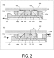
- FIG. 2 is a cross-sectional view for explaining a mechanism of the frac plug in FIG. 1 .
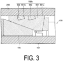
- FIG. 3 is an enlarged cross-sectional view of a framed portion B illustrated in FIG. 2 .
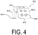
- FIG. 4 is a partial perspective view of a slip base of a slip which is a downhole tool securing device provided in the frac plug of the present embodiment.
- FIG. 5 is a partial perspective view of a button of the slip which is the downhole tool securing device provided in the frac plug of the present embodiment.
- a frac plug 100 (downhole tool) of the present embodiment includes a mandrel 101, an elastic member 102, a holding member 103 disposed adjacently to the elastic member 102 on one side of the elastic member 102, cones 104, 105 disposed to sandwich the elastic member 102 and the holding member 103, a pair of slips 106a, 106b (downhole tool securing device), and a pair of ring members 107a, 107b.
- the frac plug 100 is installed in a casing 200 disposed within the wellbore, as illustrated in FIG. 2(a) .
- the mandrel 101 is moved in the axial direction indicated by P in FIG. 2(a) to reduce the distance between the pair of ring members 107a, 107b in the axial direction of the mandrel. This allows the slips 106a, 106b to ride on upper surfaces of the slopes of the cones 104, 105 and move outwardly orthogonally to the axial direction of the mandrel 101 to be in contact with the inner wall of the wellbore (the inner wall of the casing 200).
- the frac plug 100 is installed at a predetermined position of the wellbore.
- a button 602 protrudes outwardly orthogonally to the axial direction of the mandrel 101 as described below.
- a part of the button 602 is recessed into the inner wall of the casing 200.
- the elastic member 102 As the mandrel 101 moves in the axial direction to reduce the gap between the cone 105 and the holding member 103, the elastic member 102 is deformed to expand outward in the outer circumferential direction of the axis of the mandrel 101. Then, the elastic member 102 is in contact with the casing 200, so that the space between the frac plug 100 and the casing 200 is closed.
- the wellbore is then closed by placing a ball or the like (not illustrated) in the axial hollow portion of the mandrel 101. Then, when a fluid is pumped into the closed section from the side of the cone 104 at high pressure in a state where the wellbore is closed, hydraulic fracturing is performed to create cracks in the production reservoir.
- the frac plug 100 is removed from the well once hydraulic fracturing is completed.
- the frac plug 100 of the present embodiment is a degradable frac plug formed of a degradable material that is degradable by the fluid in the well.
- the frac plug 100 is degraded, disintegrated, dissolved, and thus removed from its contact portion with the fluid, and the closed flow path is reopened.
- each of the constituent members included in the frac plug 100 is formed of a degradable resin or degradable metal. This facilitates removal of the frac plug 100 after the well treatment using the frac plug 100.
- degradable resin or degradable metal means a resin or metal which can be degraded or embrittled to be easily disintegrated, by biodegradation or hydrolysis, dissolution in water or hydrocarbons in a wellbore, or any chemical method.
- the degradable resin examples include aliphatic polyesters based on hydroxycarboxylic acid such as polylactic acid (PLA) and polyglycolic acid (PGA), lactone-based aliphatic polyesters such as poly-caprolactone (PCL), diol-dicarboxylic acid-based aliphatic polyesters such as polyethylene succinate and polybutylene succinate, copolymers thereof such as glycolic acid-lactic acid copolymers, mixtures thereof, and aliphatic polyesters using in combination aromatic components such as polyethylene adipate/terephthalate, or the like.
- a water-soluble resin may be used as the degradable resin.
- water-soluble resin examples include polyvinyl alcohol, polyvinyl butyral, polyvinyl formal, polyacrylamide (which may be N, N-substituted), polyacrylic acid, and polymethacrylic acid, and furthermore copolymers of monomers forming these resins, such as ethylene-vinyl alcohol copolymer (EVOH) and acrylamide-acrylic acid-methacrylic acid interpolymer.
- EVOH ethylene-vinyl alcohol copolymer
- the degradable metal include, for example, metal alloys containing magnesium, aluminum, and calcium as main components.
- FIG. 3 is an enlarged view of a portion B surrounded by a frame illustrated in FIG. 2(b) , and illustrates a configuration of the slip 106b. Since the slip 106a has the same configuration as that of the slip 106b illustrated in FIG. 3 , only the slip 106b will be described here.
- the slip 106b includes a slip base 601 (main body) and a button 602 attached to the slip base 601 and protruding from the surface of the slip base 601.
- the slip base 601 is a main body portion of the slip 106b, and slides on an inclined surface of the cone 105.
- An outer circumferential surface 601a of the slip base 601 is provided with a recess 601b into which the button 602 is inserted.
- a plurality of buttons 602 are provided, and a number of recesses 601b are also formed in the outer circumferential surface 601a depending on the number of buttons 602.
- the slip base 601 includes a plurality of slip divided pieces 612 divided by a cut 611 which ends halfway from one end to the other end along the axial direction. Each of the slip divided pieces 612 is provided with a plurality of buttons 602 on the surface 601a that is in contact with the casing 200.
- the embodiment of the slip base 601 is not limited to the embodiment illustrated in FIG. 4 .
- the slip base 601 may be a degradable resin or degradable metal as described above, but is preferably formed of a reactive metal that is soluble in a predetermined solvent in the well.
- the reactive metal is a metallic element that degrades by readily bonding with oxygen to form a very stable oxide, reacting with water to produce diatomic hydrogen, and/or readily absorbing oxygen, hydrogen, nitrogen, or another non-metallic element to become brittle. More specifically, the reactive metal means a an elemental metal or an alloy containing the metal element as a main component, which can be degraded by a degradation reaction based on a chemical change and thus easily deprive the original shape of the downhole tool or the downhole tool member under a predetermined condition (for example, conditions such as temperature and pressure, contact with a fluid such as an aqueous fluid (preferably an acidic fluid or the like), and the like) in a well environment (hereinafter, also called "downhole environment") in which the downhole tool is used.
- a predetermined condition for example, conditions such as temperature and pressure, contact with a fluid such as an aqueous fluid (preferably an acidic fluid or the like), and the like
- a well environment hereinafter, also called "downhole
- the predetermined solvent refers to a fluid such as a fracturing fluid (that is, a well treatment fluid used for fracturing), and examples thereof include various additives such as a channelant, a gelling agent, a scale inhibitor, an acid for dissolving a rock or the like, and a friction reducing material, in addition to water.
- a fracturing fluid that is, a well treatment fluid used for fracturing
- various additives such as a channelant, a gelling agent, a scale inhibitor, an acid for dissolving a rock or the like, and a friction reducing material, in addition to water.
- the reactive metal is an alkali metal or alkaline earth metal belonging to group I or group II of the periodic table, or aluminum or the like, but an alloy containing magnesium as a main component is preferable.
- buttons 602 are attached to the surface 601a of the slip base 601 that is in contact with the casing 200.
- FIG. 4 illustrates an embodiment in which four buttons 602 are provided in one slip divided piece 612, and the number of buttons 602 is not limited thereto. In addition, the number of buttons 602 provided with respect to the entire slip base 601 is not particularly limited.
- the button 602 is cylindrical.
- the button 602 is attached to the slip base 601 such that the central axis of the button 602 is inclined with respect to the axial direction of the mandrel 101 ( FIGS. 1 and 2 ).
- the attachment method is not particularly limited, and a known method of attaching the button to the slip base can be employed.
- the inclination angle of the central axis of the button 602 with respect to the axial direction of the mandrel 101 is, for example, 85° or less and preferably 80° or less, from the viewpoint of setting properties to a steel pipe. From the viewpoint of durability of the securing device, the inclination angle is 45° or greater and preferably 60° or greater.
- the button 602 may have a cylindrical shape with chamfered corners (edges).
- the size of the button 602 can be set as appropriate, but as an example, an outer diameter of 9 mm and a thickness (height) of 5.9 mm can be used as in an example described below.
- the button 602 includes a molded article of a powder metallurgy material and has a compressive elastic modulus of at least 13.5 GPa and a toughness of 0.23 GJ/m 3 or greater and 1.0 GJ/m 3 or less.
- the button 602 includes the molded article of the powder metallurgy material and has a compressive elastic modulus of at least 13.5 GPa and thus does not deform when being embedded in the casing 200 ( FIGS. 1 and 2 ), and exhibits excellent setting properties (securing properties).
- the button 602 includes a molded article of a powder metallurgy material and its toughness is 0.23 GJ/m 3 or greater and 1.0 GJ/m 3 or less, as described above.
- the toughness is 0.23 GJ/m 3 or greater
- the button has a strength sufficient to withstand high water pressure (for example, water pressure up to 70 MPa) during hydraulic fracturing of the production reservoir.
- the toughness is 1.0 GJ/m 3 or less, excellent crushing properties are provided.
- the button 602 can be easily removed when the frac plug 100 ( FIG. 1 ) is removed from the well. As described above, since the removal is easy, the frac plug 100 does not remain in the well to become a failure (production failure) of the next treatment when removed from the well.
- the button 602 is formed of a molded article of a powder metallurgy material, and has an apparent density of 6.7 g/cm 3 or greater and 7.2 g/cm 3 or less.
- the button 602 can be formed of, for example, a molded article of an iron powder metallurgy material. As a result, its apparent density is smaller than the specific gravity of iron of 7.8, and the button 602 is easily broken. Therefore, it is unlikely to cause a production failure.
- the button 602 includes a surface and a core, and the surface and the core each have a Rockwell hardness (HRC) of 20 or greater and 45 or less.
- HRC Rockwell hardness
- the surface of the button 602 is a portion corresponding to a surface of a cylindrical shape. A portion closer to the central portion than the surface is a portion corresponding to the core. Therefore, the surface and the core referred to herein are not separate parts from each other but represent a relative positional relationship in one molded article.
- the HRC of the surface of the button 602 may be the same as or different from the HRC of the core. Further, the HRC of the core may be different between the surface side and the central portion of the button 602 (the central portion of a cylindrical body). For example, the HRC may be continuously varied from the surface side toward the central portion of the core. When the HRC is continuously different in the core, the "HRC of the core" as used herein refers to a value obtained by measuring the central portion of the core.
- the surface and the core of the button 602 each preferably have an HRC of 30 or greater.
- buttons 602 attached to the slips 106a, 106b of the present embodiment are excellent in the setting properties (securing properties) and water pressure resistance, and has excellent fracturing properties. Therefore, when the frac plug 100 ( FIG. 1 ) is removed from the well, it can be easily removed and does not cause production failure.
- the frac plug may include a mandrel and an elastic member, and further include one slip and one corresponding cone and one corresponding ring member.
- the downhole tool securing device can also be applied to a downhole tool other than the frac plug 100, and the downhole tool is also included in the scope of the present invention.
- the downhole tool securing device (slips 106a, 106b) according to a first embodiment of the present invention is a downhole tool securing device for securing a downhole tool to a casing in a well, the device including a main body (slip base 601); and a button 602 attached to the main body and protruding from a surface 601a of the main body, wherein the button 602 includes a molded article of a powder metallurgy material, and the button 602 has a compressive elastic modulus of at least 13.5 GPa and a toughness of 0.23 GJ/m 3 or greater and 1.0 GJ/m 3 or less.
- the button 602 in the first embodiment, preferably has an apparent density of 6.7 g/cm 3 or greater and 7.2 g/cm 3 or less.
- the button 602 in the first or second embodiment, it is preferable that the button 602 includes a surface and a core, and the face and the core each have a Rockwell hardness (HRC) of 20 or greater and 45 or less.
- HRC Rockwell hardness
- the button when the button is embedded into an inner wall of the well (the inner wall of the casing), deformation can be suppressed and excellent securing properties can be exhibited.
- the main body is formed of a reactive metal that is soluble in a predetermined solvent
- the button includes a molded article of an iron powder metallurgy material.
- the frac plug 100 includes the above-described downhole tool securing device (slips 106a, 106b).
- a frac plug including a downhole tool securing device having excellent securing properties, pressure resistance, and crushing properties.
- buttons attached to the slip of the present embodiment will be described using examples.
- the button 602 illustrated in FIG. 5 was produced by using a powder metallurgy material (1) having a composition shown in Table 1, adjusting a material input amount and a compression amount to set its density to a predetermined value, and surface-hardening the button by heat treatment.
- the button 602 illustrated in FIG. 5 was produced by using a powder metallurgy material (2) having a composition shown in Table 1, adjusting a material input amount and a compression amount to set its density to a predetermined value, and surface-hardening the button by heat treatment.
- Table 1 Composition
- Composition [%] Material Fe C Cu Mn Mo Ni Cr Others
- Example 1 Powder metallurgy material (1) Remaining constituent 0.1 to 0.5 1 to 3 0.05 to 0.45 0.2 to 0.6 - - Less than 1
- an extruded material of tool steel (SKD11) was cut into a button shape and heat-treated to produce a button.
- a button was produced in the same manner as in Comparative Examples 1 and 2 except that an extruded material of structural alloy steel (SCM415) was used instead of the extruded material of the tool steel (SKD11), and the heat treatment condition was set to a condition for surface hardening.
- SCM415 structural alloy steel
- SSD11 tool steel
- the compositions of the buttons of Comparative Examples 1 to 3 are summarized in Table 2.
- a molded article of yttria-based zirconia (1) was used as a button.
- a molded article of magnesia-based zirconia was used as a button.
- the hardness of the button surface was measured as follows. After an upper surface of the cylindrical button was polished and smoothed, an indenter of a micro Vickers hardness tester (Vickers hardness tester HV-114 available from Mitutoyo Corporation) was pressed against the button with a load 50 kgf at room temperature, and the hardness was calculated from a diagonal length of the indentation and a test load. As for the hardness of a core layer, the button was cut in a direction perpendicular to the axial direction of the cylindrical button, the cut surface was polished and smoothed, and then the hardness of the central portion of the cross section was measured in the same manner as for the surface hardness. With respect to the Rockwell hardness (HRC), the Vickers hardness obtained by the above method was converted in accordance with ASTM E140 Table 2.
- HRC Rockwell hardness
- the weight of the button in air at 23°C and the weight of the button in ion-exchanged water were measured, and the apparent density was calculated from the obtained weights and the density of the ion-exchanged water according to the Archimedes principle.
- the cylindrical button was sandwiched between two tungsten carbide plates so that a bottom surface and an upper surface of the button were in contact with the tungsten carbide plates, and uniaxially compressed at a compression rate of 2 mm/min in the axial direction of the button at room temperature to obtain a strain-stress curve.
- the compressive elastic modulus was calculated in a section where the stress linearly changes over the strain.
- a crack was generated in the button with compression, and a point at which a maximum value was exhibited was defined as the compressive strength.
- the toughness was calculated by integrating the strain-stress curve in the section up to the strain at which the crack occurred.
- composition analysis (ceramic)
- X-ray fluorescence (XRF) measurements were performed to determine the elemental composition of the ceramic buttons. Using a fundamental parameter (FP) method, the XRF peak intensity of each element was converted to a concentration ratio from the measurement results.
- FP fundamental parameter
- the frac plug 100 ( FIG. 1 ) provided with the slips 106a, 106b was prepared.
- Polyglycolic acid (PGA) was used for the mandrel 101.
- Polyurethane was used for the elastic member 102.
- PGA was used for the holding member 103.
- PGA was used for the cone 104, a magnesium alloy was used for the cone 105, and in the pair of slips 106a, 106b, a magnesium alloy was used for the slip base 601 ( FIG. 3 ) and the button described in "(1) Production method of button" was used for the button 602.
- PGA was used for the pair of ring members 107a, 107b.
- a sample was evaluated as "Good” when the frac plug held a water pressure for 30 minutes or longer, a sample was evaluated as “Margin” when the frac plug held a water pressure for 30 minutes or longer, and the frac plug was moved by 10 mm or greater after the application of the water pressure with respect to the position of the member including the slips 106a, 106b at the time of setting the frac plug in the steel pipe, and a sample was evaluated as "Poor” when the securing member was damaged and the water pressure can not be held for 30 minutes or longer.
- the buttons of Example 1 and Example 2 are powder metallurgy materials having a toughness in the range of 0.23 GJ/m 3 to 1.0 GJ/m 3 and an apparent density in the range of 6.7 g/cm 3 to 7.2 g/cm 3 .
- the buttons of Examples 1 and 2 had excellent fracturing properties after hydraulic fracturing.
- Comparative Examples 1 to 3 had a toughness exceeding 1.0 GJ/m 3 , and thus it was shown that the crushing properties were not sufficient.
Landscapes
- Engineering & Computer Science (AREA)
- Chemical & Material Sciences (AREA)
- Life Sciences & Earth Sciences (AREA)
- Geology (AREA)
- Mining & Mineral Resources (AREA)
- Organic Chemistry (AREA)
- Metallurgy (AREA)
- Mechanical Engineering (AREA)
- Materials Engineering (AREA)
- Fluid Mechanics (AREA)
- Geochemistry & Mineralogy (AREA)
- General Life Sciences & Earth Sciences (AREA)
- Physics & Mathematics (AREA)
- Environmental & Geological Engineering (AREA)
- Powder Metallurgy (AREA)
- Earth Drilling (AREA)
- Pressure Vessels And Lids Thereof (AREA)
- Carbon Steel Or Casting Steel Manufacturing (AREA)
Abstract
Description
- The present invention relates to a downhole tool securing device and a frac plug.
- In order to efficiently collect and recover hydrocarbon resources such as petroleum such as shale oil or natural gas such as shale gas, it is known to stimulate a production reservoir that produces these hydrocarbon resources by hydraulic fracturing. The hydraulic fracturing method is a method for generating pores, cracks (fractures), or the like in the production reservoir by a fluid pressure such as hydraulic pressure and efficiently collecting and recovering hydrocarbon resources through the fractures or the like. Between the ground surface and the production reservoir, a hole for forming a well called a downhole is provided. In the downhole, a vertical hole is drilled from the ground surface and subsequently bent to form a horizontal hole in the production reservoir located several thousand meters underground.
- When the hydraulic fracturing method is applied to such a downhole, a downhole tool for closing a wellbore during hydraulic fracturing is installed in the downhole. In the installation, first, the downhole tool is sent to a predetermined position of the downhole. Then, while the downhole tool is operated to be secured to the wall of the downhole, an elastic member included in the downhole tool is deformed to close the downhole. Thereafter, water is pumped from the ground into the downhole to apply water pressure to an area closer to the ground than the previously closed position. In the production reservoir, pores are separately formed by using an explosive or the like, and cracks are generated from the pores by further applying water pressure.
- The downhole tool, called a frac plug or the like, includes at least one mandrel and various members attached to the outer circumferential surface of the mandrel. On the outer circumferential surface of the mandrel, provided are a sealing member made of an elastic material and a securing device called a slip in order to ensure tight-securing to the wall of the downhole.
- In addition, since the downhole tool is used to temporarily close the downhole, it is necessary to remove the downhole tool after use, and in order to facilitate the removal, development of a downhole tool having degradability has also been advanced.
- Patent Document 1 discloses an embodiment in which a downhole tool is secured to a downhole by a cylindrical insert or button called a gripping element provided on a surface of a slip. It is disclosed that the gripping element is made of a powder metallurgy material in consideration of degradability, and is surface-hardened so that the surface layer has a Rockwell hardness of 55 to 62 HRC (or 40 to 80 HRC) and the core has a 15-N Rockwell hardness of 75 (about 30 in terms of HRC) or 70 to 97 (about 21 to more than 68 in terms of HRC).
- Patent Document 2 also discloses a configuration in which an insert (button) is provided on a surface of a slip segment. It is disclosed that the insert is made of a powder metallurgy material and has sufficient strength and hardness to engage with the casing and secure the tool.
- In addition, Patent Document 3 also discloses a configuration including an insert on a surface of a slip, and discloses that the insert can use a powder metallurgy material having a hardness of 50 to 60 Rc.
- In addition, Patent Document 4 discloses a slip using powder metallurgy having a Rockwell C hardness of 55 to 60.
-
- Patent Document 1:
US 2018/0128073 - Patent Document 2:
US 2014/0224477 - Patent Document 3:
US 2015/0368994 - Patent Document 4:
US 2017/0044859 - The button attached to the slip needs to be strong enough to withstand high water pressure, for example, up to 70 MPa, while being secured to the wall of the downhole (or a casing provided on the wall). On the other hand, considering that the downhole tool is degraded after the production reservoir is cracked as described above, the button also needs to have crushing properties.
- Therefore, an object of one embodiment of the present invention is to realize a downhole tool securing device and a frac plug, which are excellent in securing properties, pressure resistance, and crushing properties.
- In order to solve the above problems, a downhole tool securing device according to an embodiment of the present invention is a downhole tool securing device for securing a downhole tool to a casing in a well, the device including a main body; and a button attached to the main body and protruding from a surface of the main body, wherein the button includes a molded article of a powder metallurgy material, and the button has a compressive elastic modulus of at least 13.5 GPa and a toughness of 0.23 GJ/m3 or greater and 1.0 GJ/m3 or less.
- In order to solve the above problems, a frac plug according to an embodiment of the present invention includes the downhole tool securing device described above.
- According to an embodiment of the present invention, it is possible to realize a downhole tool securing device and a frac plug, which are excellent in securing properties, pressure resistance, and crushing properties.
-
-
FIG. 1 is a side view of a frac plug including a downhole tool securing device according to an embodiment of the present invention. -
FIG. 2 is a partial cross-sectional view of the frac plug ofFIG. 1 . -
FIG. 3 is an enlarged cross-sectional view of a part ofFIG. 1 , and is a cross-sectional view illustrating a configuration of the downhole tool securing device according to the embodiment of the present invention. -
FIG. 4 is a partial perspective view of a slip base of a slip which is the downhole tool securing device according the embodiment of the present invention. -
FIG. 5 is a partial perspective view of a button which is the downhole tool securing device according to the embodiment of the present invention. - Hereinafter, an embodiment of a downhole tool securing device and a frac plug according to the present invention will be described with reference to
FIGS. 1 to 3 . -
FIG. 1 is a side view of a frac plug (downhole tool) of the present embodiment.FIG. 2 is a cross-sectional view for explaining a mechanism of the frac plug inFIG. 1 .FIG. 3 is an enlarged cross-sectional view of a framed portion B illustrated inFIG. 2 .FIG. 4 is a partial perspective view of a slip base of a slip which is a downhole tool securing device provided in the frac plug of the present embodiment.FIG. 5 is a partial perspective view of a button of the slip which is the downhole tool securing device provided in the frac plug of the present embodiment. - As illustrated in
FIG. 1 , a frac plug 100 (downhole tool) of the present embodiment includes amandrel 101, anelastic member 102, aholding member 103 disposed adjacently to theelastic member 102 on one side of theelastic member 102,cones elastic member 102 and theholding member 103, a pair ofslips ring members - In a wellbore (not illustrated), the
frac plug 100 is installed in acasing 200 disposed within the wellbore, as illustrated inFIG. 2(a) . When thefrac plug 100 is installed in thecasing 200, themandrel 101 is moved in the axial direction indicated by P inFIG. 2(a) to reduce the distance between the pair ofring members slips cones mandrel 101 to be in contact with the inner wall of the wellbore (the inner wall of the casing 200). As a result, thefrac plug 100 is installed at a predetermined position of the wellbore. Here, in theslips button 602 protrudes outwardly orthogonally to the axial direction of themandrel 101 as described below. As a result, in a state where theslips 106a, 106 are in contact with the inner wall of the wellbore (the inner wall of the casing 200), a part of thebutton 602 is recessed into the inner wall of thecasing 200. Thus, thefrac plug 100 can be firmly secured to the inner wall of the wellbore. - As the
mandrel 101 moves in the axial direction to reduce the gap between thecone 105 and theholding member 103, theelastic member 102 is deformed to expand outward in the outer circumferential direction of the axis of themandrel 101. Then, theelastic member 102 is in contact with thecasing 200, so that the space between thefrac plug 100 and thecasing 200 is closed. - After the
frac plug 100 is installed at a predetermined position of the wellbore as described above, the wellbore is then closed by placing a ball or the like (not illustrated) in the axial hollow portion of themandrel 101. Then, when a fluid is pumped into the closed section from the side of thecone 104 at high pressure in a state where the wellbore is closed, hydraulic fracturing is performed to create cracks in the production reservoir. - The
frac plug 100 is removed from the well once hydraulic fracturing is completed. Thefrac plug 100 of the present embodiment is a degradable frac plug formed of a degradable material that is degradable by the fluid in the well. By being exposed to the fluid in the well (the fluid flowing in the axial direction of the mandrel, that is, in the direction of arrow F1 or F2 inFIG. 2(b) ) for a predetermined time, thefrac plug 100 is degraded, disintegrated, dissolved, and thus removed from its contact portion with the fluid, and the closed flow path is reopened. In order to realize this, it is preferable that each of the constituent members included in thefrac plug 100 is formed of a degradable resin or degradable metal. This facilitates removal of thefrac plug 100 after the well treatment using thefrac plug 100. - In the present specification, the term "degradable resin or degradable metal" means a resin or metal which can be degraded or embrittled to be easily disintegrated, by biodegradation or hydrolysis, dissolution in water or hydrocarbons in a wellbore, or any chemical method. Examples of the degradable resin include aliphatic polyesters based on hydroxycarboxylic acid such as polylactic acid (PLA) and polyglycolic acid (PGA), lactone-based aliphatic polyesters such as poly-caprolactone (PCL), diol-dicarboxylic acid-based aliphatic polyesters such as polyethylene succinate and polybutylene succinate, copolymers thereof such as glycolic acid-lactic acid copolymers, mixtures thereof, and aliphatic polyesters using in combination aromatic components such as polyethylene adipate/terephthalate, or the like. Furthermore, a water-soluble resin may be used as the degradable resin. Examples of the water-soluble resin include polyvinyl alcohol, polyvinyl butyral, polyvinyl formal, polyacrylamide (which may be N, N-substituted), polyacrylic acid, and polymethacrylic acid, and furthermore copolymers of monomers forming these resins, such as ethylene-vinyl alcohol copolymer (EVOH) and acrylamide-acrylic acid-methacrylic acid interpolymer. Examples of the degradable metal include, for example, metal alloys containing magnesium, aluminum, and calcium as main components.
-
FIG. 3 is an enlarged view of a portion B surrounded by a frame illustrated inFIG. 2(b) , and illustrates a configuration of theslip 106b. Since theslip 106a has the same configuration as that of theslip 106b illustrated inFIG. 3 , only theslip 106b will be described here. - As illustrated in
FIG. 3 , theslip 106b includes a slip base 601 (main body) and abutton 602 attached to theslip base 601 and protruding from the surface of theslip base 601. - The
slip base 601 is a main body portion of theslip 106b, and slides on an inclined surface of thecone 105. - An outer
circumferential surface 601a of theslip base 601 is provided with arecess 601b into which thebutton 602 is inserted. A plurality ofbuttons 602 are provided, and a number ofrecesses 601b are also formed in the outercircumferential surface 601a depending on the number ofbuttons 602. - One embodiment of the
slip base 601 will be described with reference toFIG. 4 . Theslip base 601 includes a plurality of slip dividedpieces 612 divided by acut 611 which ends halfway from one end to the other end along the axial direction. Each of the slip dividedpieces 612 is provided with a plurality ofbuttons 602 on thesurface 601a that is in contact with thecasing 200. The embodiment of theslip base 601 is not limited to the embodiment illustrated inFIG. 4 . - The
slip base 601 may be a degradable resin or degradable metal as described above, but is preferably formed of a reactive metal that is soluble in a predetermined solvent in the well. - The reactive metal is a metallic element that degrades by readily bonding with oxygen to form a very stable oxide, reacting with water to produce diatomic hydrogen, and/or readily absorbing oxygen, hydrogen, nitrogen, or another non-metallic element to become brittle. More specifically, the reactive metal means a an elemental metal or an alloy containing the metal element as a main component, which can be degraded by a degradation reaction based on a chemical change and thus easily deprive the original shape of the downhole tool or the downhole tool member under a predetermined condition (for example, conditions such as temperature and pressure, contact with a fluid such as an aqueous fluid (preferably an acidic fluid or the like), and the like) in a well environment (hereinafter, also called "downhole environment") in which the downhole tool is used.
- The predetermined solvent refers to a fluid such as a fracturing fluid (that is, a well treatment fluid used for fracturing), and examples thereof include various additives such as a channelant, a gelling agent, a scale inhibitor, an acid for dissolving a rock or the like, and a friction reducing material, in addition to water.
- A person skilled in the art can appropriately select the range of the reactive metal according to a predetermined condition such as an assumed well environment. In many cases, the reactive metal is an alkali metal or alkaline earth metal belonging to group I or group II of the periodic table, or aluminum or the like, but an alloy containing magnesium as a main component is preferable.
- As illustrated in
FIG. 3 , thebutton 602 is attached to thesurface 601a of theslip base 601 that is in contact with thecasing 200.FIG. 4 illustrates an embodiment in which fourbuttons 602 are provided in one slip dividedpiece 612, and the number ofbuttons 602 is not limited thereto. In addition, the number ofbuttons 602 provided with respect to theentire slip base 601 is not particularly limited. - As illustrated in
FIG. 5 , thebutton 602 is cylindrical. Thebutton 602 is attached to theslip base 601 such that the central axis of thebutton 602 is inclined with respect to the axial direction of the mandrel 101 (FIGS. 1 and2 ). The attachment method is not particularly limited, and a known method of attaching the button to the slip base can be employed. - The inclination angle of the central axis of the
button 602 with respect to the axial direction of themandrel 101 is, for example, 85° or less and preferably 80° or less, from the viewpoint of setting properties to a steel pipe. From the viewpoint of durability of the securing device, the inclination angle is 45° or greater and preferably 60° or greater. Thebutton 602 may have a cylindrical shape with chamfered corners (edges). - The size of the
button 602 can be set as appropriate, but as an example, an outer diameter of 9 mm and a thickness (height) of 5.9 mm can be used as in an example described below. - The
button 602 includes a molded article of a powder metallurgy material and has a compressive elastic modulus of at least 13.5 GPa and a toughness of 0.23 GJ/m3 or greater and 1.0 GJ/m3 or less. Thebutton 602 includes the molded article of the powder metallurgy material and has a compressive elastic modulus of at least 13.5 GPa and thus does not deform when being embedded in the casing 200 (FIGS. 1 and2 ), and exhibits excellent setting properties (securing properties). - In addition, the
button 602 includes a molded article of a powder metallurgy material and its toughness is 0.23 GJ/m3 or greater and 1.0 GJ/m3 or less, as described above. When the toughness is 0.23 GJ/m3 or greater, the button has a strength sufficient to withstand high water pressure (for example, water pressure up to 70 MPa) during hydraulic fracturing of the production reservoir. On the other hand, since the toughness is 1.0 GJ/m3 or less, excellent crushing properties are provided. As such, thebutton 602 can be easily removed when the frac plug 100 (FIG. 1 ) is removed from the well. As described above, since the removal is easy, thefrac plug 100 does not remain in the well to become a failure (production failure) of the next treatment when removed from the well. - Preferably, the
button 602 is formed of a molded article of a powder metallurgy material, and has an apparent density of 6.7 g/cm3 or greater and 7.2 g/cm3 or less. Thebutton 602 can be formed of, for example, a molded article of an iron powder metallurgy material. As a result, its apparent density is smaller than the specific gravity of iron of 7.8, and thebutton 602 is easily broken. Therefore, it is unlikely to cause a production failure. - The
button 602 includes a surface and a core, and the surface and the core each have a Rockwell hardness (HRC) of 20 or greater and 45 or less. Here, the surface of thebutton 602 is a portion corresponding to a surface of a cylindrical shape. A portion closer to the central portion than the surface is a portion corresponding to the core. Therefore, the surface and the core referred to herein are not separate parts from each other but represent a relative positional relationship in one molded article. - The HRC of the surface of the
button 602 may be the same as or different from the HRC of the core. Further, the HRC of the core may be different between the surface side and the central portion of the button 602 (the central portion of a cylindrical body). For example, the HRC may be continuously varied from the surface side toward the central portion of the core. When the HRC is continuously different in the core, the "HRC of the core" as used herein refers to a value obtained by measuring the central portion of the core. - In addition, from the viewpoint of the setting properties and the water pressure resistance, the surface and the core of the
button 602 each preferably have an HRC of 30 or greater. - As described above, the
buttons 602 attached to theslips FIG. 1 ) is removed from the well, it can be easily removed and does not cause production failure. - As another embodiment of the frac plug according to the present invention, the frac plug may include a mandrel and an elastic member, and further include one slip and one corresponding cone and one corresponding ring member.
- The present invention is not limited to the embodiments described above, and various modifications are possible within the scope indicated in the claims, which are also included in the technical scope of the present invention.
- Further, the downhole tool securing device according to an embodiment of the present invention (
slips frac plug 100, and the downhole tool is also included in the scope of the present invention. - The downhole tool securing device (
slips button 602 attached to the main body and protruding from asurface 601a of the main body, wherein thebutton 602 includes a molded article of a powder metallurgy material, and thebutton 602 has a compressive elastic modulus of at least 13.5 GPa and a toughness of 0.23 GJ/m3 or greater and 1.0 GJ/m3 or less. - According to the configuration of the first embodiment, it is possible to realize a downhole tool securing device having excellent securing properties, pressure resistance, and crushing properties.
- In a downhole tool securing device (
slips button 602 preferably has an apparent density of 6.7 g/cm3 or greater and 7.2 g/cm3 or less. - According to the configuration of the second embodiment, it is possible to realize a downhole tool securing device having excellent crushing properties.
- In a downhole tool securing device (
slips button 602 includes a surface and a core, and the face and the core each have a Rockwell hardness (HRC) of 20 or greater and 45 or less. - According to the configuration of the third embodiment, when the button is embedded into an inner wall of the well (the inner wall of the casing), deformation can be suppressed and excellent securing properties can be exhibited.
- In a downhole tool securing device (
slips - The
frac plug 100 according to a fifth embodiment of the present invention includes the above-described downhole tool securing device (slips - According to the configuration of the fifth embodiment, it is possible to realize a frac plug including a downhole tool securing device having excellent securing properties, pressure resistance, and crushing properties.
- Hereinafter, the button attached to the slip of the present embodiment will be described using examples.
- The
button 602 illustrated inFIG. 5 was produced by using a powder metallurgy material (1) having a composition shown in Table 1, adjusting a material input amount and a compression amount to set its density to a predetermined value, and surface-hardening the button by heat treatment. - The
button 602 illustrated inFIG. 5 was produced by using a powder metallurgy material (2) having a composition shown in Table 1, adjusting a material input amount and a compression amount to set its density to a predetermined value, and surface-hardening the button by heat treatment.[Table 1] Composition [%] Material Fe C Cu Mn Mo Ni Cr Others Example 1 Powder metallurgy material (1) Remaining constituent 0.1 to 0.5 1 to 3 0.05 to 0.45 0.2 to 0.6 - - Less than 1 Example 2 Powder metallurgy material (2) Remaining constituent 0.2 to 0.6 1 to 3 - 0.2 to 0.7 3 to 5 - Less than 1 - As a comparative example, an extruded material of tool steel (SKD11) was cut into a button shape and heat-treated to produce a button.
- A button was produced in the same manner as in Comparative Examples 1 and 2 except that an extruded material of structural alloy steel (SCM415) was used instead of the extruded material of the tool steel (SKD11), and the heat treatment condition was set to a condition for surface hardening. The compositions of the buttons of Comparative Examples 1 to 3 are summarized in Table 2.
[Table 2] Composition [%] Material Fe C Si Mn P S Cr Mo V Cu Ni Comparative Examples 1 and 2 SKD11 Remaining constituent 1.4 to 1.6 0.15 to 0.35 0.3 to 0.6 0.025 or less 0.010 or less 11 to 13 0.8 to 1.2 0.2 to 0.5 - - Comparative Example 3 SCM415 Remaining constituent 0.12 to 0.18 0.15 to 0.35 0.55 to 0.95 0.030 or less 0.030 or less 0.85 to 1.25 0.15 to 0.3 - 0.3 or less 0.25 or less - As a comparative example, by using a powder metallurgy material (3) having a composition shown in Table 3, a material input amount and a compression amount were adjusted to set its density to a predetermined value, and a button that was surface-hardened by heat treatment was produced.
[Table 3] Composition [%] Material Fe C Cu Mn Mo Ni Cr Others Comparative Examples 4 and 5 Powder metallurgy material (3) Remaining constituent 0.2 to 0.8 1 to 2 - 0.2 to 0.7 3 to 5 - Less than 1 - As a comparative example, a molded article of yttria-based zirconia (1) was used as a button.
- As a comparative example, a molded article of magnesia-based zirconia was used as a button.
- As a comparative example, a molded article of yttria-based zirconia (2) was used as a button.
- The compositions of the buttons of Comparative Examples 6 to 8 are summarized in Table 4.
[Table 4] Composition [%] Material Fe Cu Mn Mo Ni Al Ca Cr Mg Na P Si Cl Hf O Y Zr Comparative Example 6 Yttria-based zirconia (1) - - - - 0.04 0.20 - - - 0.20 0.01 0.01 0.20 1.2 36 3.7 59 Comparative Example 7 Magnesia-based zirconia - - - - - 0.20 - - 1.7 - - 0.1 - 1.4 35 0.1 62 Comparative Example 8 Yttria-based zirconia (2) - - - - 0.1 0.1 - - 0.1 0.30 - - 0.20 1.5 32 4.0 62 - Various characteristics of each button produced by the above-described production method were measured as follows.
- The hardness of the button surface was measured as follows. After an upper surface of the cylindrical button was polished and smoothed, an indenter of a micro Vickers hardness tester (Vickers hardness tester HV-114 available from Mitutoyo Corporation) was pressed against the button with a load 50 kgf at room temperature, and the hardness was calculated from a diagonal length of the indentation and a test load. As for the hardness of a core layer, the button was cut in a direction perpendicular to the axial direction of the cylindrical button, the cut surface was polished and smoothed, and then the hardness of the central portion of the cross section was measured in the same manner as for the surface hardness. With respect to the Rockwell hardness (HRC), the Vickers hardness obtained by the above method was converted in accordance with ASTM E140 Table 2.
- The weight of the button in air at 23°C and the weight of the button in ion-exchanged water were measured, and the apparent density was calculated from the obtained weights and the density of the ion-exchanged water according to the Archimedes principle.
- The cylindrical button was sandwiched between two tungsten carbide plates so that a bottom surface and an upper surface of the button were in contact with the tungsten carbide plates, and uniaxially compressed at a compression rate of 2 mm/min in the axial direction of the button at room temperature to obtain a strain-stress curve. The compressive elastic modulus was calculated in a section where the stress linearly changes over the strain. A crack was generated in the button with compression, and a point at which a maximum value was exhibited was defined as the compressive strength. The toughness was calculated by integrating the strain-stress curve in the section up to the strain at which the crack occurred.
- X-ray fluorescence (XRF) measurements were performed to determine the elemental composition of the ceramic buttons. Using a fundamental parameter (FP) method, the XRF peak intensity of each element was converted to a concentration ratio from the measurement results.
- The frac plug 100 (
FIG. 1 ) provided with theslips mandrel 101. Polyurethane was used for theelastic member 102. PGA was used for the holdingmember 103. PGA was used for thecone 104, a magnesium alloy was used for thecone 105, and in the pair ofslips FIG. 3 ) and the button described in "(1) Production method of button" was used for thebutton 602. PGA was used for the pair ofring members - After the above-described frac plug was disposed in the casing (steel pipe), a compressive load of 150 kN was applied to the members including the
slips mandrel 101 to bring the members including theslips - After the frac plug was secured to the steel pipe by the method described in section Set test, water was fed and sealed in the steel pipe while the steel pipe was heated to a temperature of 200 degF. After sealing, water pressure of 10000 psi (about 70 MPa) was applied to the frac plug by a pump, and it was checked whether the frac plug was able to hold the water pressure for 30 minutes or longer. A sample was evaluated as "Good" when the frac plug held a water pressure for 30 minutes or longer, a sample was evaluated as "Margin" when the frac plug held a water pressure for 30 minutes or longer, and the frac plug was moved by 10 mm or greater after the application of the water pressure with respect to the position of the member including the
slips - The characteristics of the buttons and the frac plugs of Examples 1 to 3 and Comparative Examples 1 to 8 described above are summarized in Table 5.
[Table 5] Sample Vickers hardness HV Rockwell HRC (converted value) Density Set test Water pressure resistance test Compression test Material Outer diameter [mm] Thickness [mm] Surface Core Surface Core [g/cm3] Elastic modulus [GPa] Compression strength [GPa] Toughness [GJ/m3] Comparative Example 1 SKD11 9 5 - - - - 7.7 Good Good 19.6 5.4 or greater 2.05 or greater Comparative Example 2 5.9 656 701 58 60 Good Good 22.0 5.4 or greater 2.07 or greater Comparative Example 3 SCM415 603 380 56 39 7.8 Good Good 22.8 5.6 or greater 2.03 or greater Comparative Example 4 Powder metallurgy material (3) (6.5) 269 305 25 30 6.6 Poor Good 12.5 1.8 0.28 Comparative Example 5 Powder metallurgy material (3) (6.9) 321 374 32 38 7.0 Poor Good 11.9 2.4 0.48 Example 1 Powder metallurgy material (1) 383 373 39 38 6.9 Good Good 15.0 2.4 0.44 Example 2 Powder metallurgy material (2) 409 397 42 40 7.0 Good Good 14.1 2.6 0.58 Comparative Example 6 Yttria-based zirconia (1) 9.525 6.35 1311 - 91 - 6.0 Good Margin 25.4 3.0 0.18 Comparative Example 7 Magnesia-based zirconia 9 5.9 904 - 67 - 5.7 Good Poor 24.2 1.9 0.08 Comparative Example 8 Yttria-based zirconia (2) 5.7 1231 - 84 - 6.0 Good Poor 26.3 2.9 0.16 - As shown in Table 5, it was shown that the buttons of Example 1 and Example 2 had good setting properties and water pressure resistance. On the other hand, all of Comparative Examples 4 to 8 were shown to have insufficient setting properties or water pressure resistance.
- The buttons of Example 1 and Example 2 are powder metallurgy materials having a toughness in the range of 0.23 GJ/m3 to 1.0 GJ/m3 and an apparent density in the range of 6.7 g/cm3 to 7.2 g/cm3. The buttons of Examples 1 and 2 had excellent fracturing properties after hydraulic fracturing.
- On the other hand, Comparative Examples 1 to 3 had a toughness exceeding 1.0 GJ/m3, and thus it was shown that the crushing properties were not sufficient.
-
- 101 Mandrel
- 100 Frac plug (downhole tool)
- 102 Elastic member
- 103 Holding member
- 104, 105 Cone
- 106a, 106b slip (downhole tool securing device)
- 200 Casing
- 601 Slip base (main body)
- 601a Outer circumferential surface (surface of main body)
- 601b Recess
- 602 Button
Claims (5)
- A downhole tool securing device for securing a downhole tool to a casing in a well, the device comprising:a main body; anda button attached to the main body and protruding from a surface of the main body,wherein the button includes a molded article of a powder metallurgy material, andthe button has a compressive elastic modulus of at least 13.5 GPa and a toughness of 0.23 GJ/m3 or greater and 1.0 GJ/m3 or less.
- The downhole tool securing device according to claim 1,
wherein the button has an apparent density of 6.7 g/cm3 or greater and 7.2 g/cm3 or less. - The downhole tool securing device according to claim 1 or 2, wherein the button is formed of a surface and a core, and
each of the surface and the core has a Rockwell hardness (HRC) of 20 or greater and 45 or less. - The downhole tool securing device according to any one of claims 1 to 3,wherein the main body is formed of a reactive metal that is soluble in a predetermined solvent, andthe button includes a molded article of an iron powder metallurgy material.
- A frac plug comprising
the downhole tool securing device described in any one of claims 1 to 4.
Applications Claiming Priority (2)
| Application Number | Priority Date | Filing Date | Title |
|---|---|---|---|
| JP2021031136 | 2021-02-26 | ||
| PCT/JP2022/007584 WO2022181685A1 (en) | 2021-02-26 | 2022-02-24 | Downhole tool securing device and frac plug |
Publications (3)
| Publication Number | Publication Date |
|---|---|
| EP4299877A1 true EP4299877A1 (en) | 2024-01-03 |
| EP4299877A4 EP4299877A4 (en) | 2024-07-24 |
| EP4299877B1 EP4299877B1 (en) | 2025-10-01 |
Family
ID=83049046
Family Applications (1)
| Application Number | Title | Priority Date | Filing Date |
|---|---|---|---|
| EP22759720.0A Active EP4299877B1 (en) | 2021-02-26 | 2022-02-24 | Downhole tool securing device and frac plug |
Country Status (4)
| Country | Link |
|---|---|
| US (1) | US12110758B2 (en) |
| EP (1) | EP4299877B1 (en) |
| CN (1) | CN116802379B (en) |
| WO (1) | WO2022181685A1 (en) |
Family Cites Families (9)
| Publication number | Priority date | Publication date | Assignee | Title |
|---|---|---|---|---|
| US10337279B2 (en) | 2014-04-02 | 2019-07-02 | Magnum Oil Tools International, Ltd. | Dissolvable downhole tools comprising both degradable polymer acid and degradable metal alloy elements |
| US9416617B2 (en) * | 2013-02-12 | 2016-08-16 | Weatherford Technology Holdings, Llc | Downhole tool having slip inserts composed of different materials |
| US9803439B2 (en) | 2013-03-12 | 2017-10-31 | Baker Hughes | Ferrous disintegrable powder compact, method of making and article of same |
| US20180128073A1 (en) | 2016-11-08 | 2018-05-10 | Magnum Oil Tools International, Ltd. | Powder metal gripping elements for settable downhole tools having slips |
| NO3120944T3 (en) | 2014-06-18 | 2018-10-20 | ||
| US20170044859A1 (en) | 2015-08-10 | 2017-02-16 | Tyler W. Blair | Slip Element and Assembly for Oilfield Tubular Plug |
| US20170314103A1 (en) | 2016-05-02 | 2017-11-02 | Schlumberger Technology Corporation | Degradable carbide grip |
| WO2019146359A1 (en) * | 2018-01-29 | 2019-08-01 | 株式会社クレハ | Degradable downhole plug |
| CN109944571A (en) * | 2019-03-26 | 2019-06-28 | 成都维泰油气能源技术有限公司 | A lightweight ball seat |
-
2022
- 2022-02-24 WO PCT/JP2022/007584 patent/WO2022181685A1/en not_active Ceased
- 2022-02-24 CN CN202280011549.3A patent/CN116802379B/en active Active
- 2022-02-24 EP EP22759720.0A patent/EP4299877B1/en active Active
- 2022-02-24 US US18/547,246 patent/US12110758B2/en active Active
Also Published As
| Publication number | Publication date |
|---|---|
| CN116802379A (en) | 2023-09-22 |
| EP4299877B1 (en) | 2025-10-01 |
| WO2022181685A1 (en) | 2022-09-01 |
| CA3209302A1 (en) | 2022-09-01 |
| EP4299877A4 (en) | 2024-07-24 |
| US12110758B2 (en) | 2024-10-08 |
| US20240052720A1 (en) | 2024-02-15 |
| CN116802379B (en) | 2026-03-24 |
Similar Documents
| Publication | Publication Date | Title |
|---|---|---|
| US8403037B2 (en) | Dissolvable tool and method | |
| US10669797B2 (en) | Tool configured to dissolve in a selected subsurface environment | |
| US8714268B2 (en) | Method of making and using multi-component disappearing tripping ball | |
| US9080439B2 (en) | Disintegrable deformation tool | |
| US8790430B1 (en) | Polycrystalline diamond compact including a polycrystalline diamond table with a thermally-stable region having a copper-containing material and applications therefor | |
| US7493973B2 (en) | Polycrystalline diamond materials having improved abrasion resistance, thermal stability and impact resistance | |
| US20180171757A1 (en) | Multifunctional downhole tools | |
| US20100012389A1 (en) | Methods of forming polycrystalline diamond cutters | |
| EP2765274A2 (en) | Downhole tool having slip inserts composed of different materials | |
| PL236865B1 (en) | Disintegrating metallic cone, process of its production and its applications | |
| EP3378586B1 (en) | Polycrystalline-diamond sintered compact tool having exceptional interface joining strength, and method for manufacturing said tool | |
| JP7532357B2 (en) | Binder redistribution within mining cemented carbide inserts. | |
| EP3241979A1 (en) | Degradable carbide grip | |
| US11761296B2 (en) | Downhole tools comprising degradable components | |
| EP4299877B1 (en) | Downhole tool securing device and frac plug | |
| EP3241978A1 (en) | Multiple portion grip | |
| US11008815B2 (en) | Cutting elements with impact resistant diamond body | |
| CA2982940C (en) | Mmc downhole tool region comprising an allotropic material | |
| EP1935537A2 (en) | Multiple processes of high pressures and temperatures for sintered bodies | |
| EP4555115B1 (en) | Rock drill insert | |
| JP2006104540A (en) | Cemented carbide | |
| CN112240293A (en) | Wear-resistant fluid end |
Legal Events
| Date | Code | Title | Description |
|---|---|---|---|
| STAA | Information on the status of an ep patent application or granted ep patent |
Free format text: STATUS: THE INTERNATIONAL PUBLICATION HAS BEEN MADE |
|
| PUAI | Public reference made under article 153(3) epc to a published international application that has entered the european phase |
Free format text: ORIGINAL CODE: 0009012 |
|
| STAA | Information on the status of an ep patent application or granted ep patent |
Free format text: STATUS: REQUEST FOR EXAMINATION WAS MADE |
|
| 17P | Request for examination filed |
Effective date: 20230809 |
|
| AK | Designated contracting states |
Kind code of ref document: A1 Designated state(s): AL AT BE BG CH CY CZ DE DK EE ES FI FR GB GR HR HU IE IS IT LI LT LU LV MC MK MT NL NO PL PT RO RS SE SI SK SM TR |
|
| DAV | Request for validation of the european patent (deleted) | ||
| DAX | Request for extension of the european patent (deleted) | ||
| A4 | Supplementary search report drawn up and despatched |
Effective date: 20240624 |
|
| RIC1 | Information provided on ipc code assigned before grant |
Ipc: C22C 23/02 20060101ALI20240618BHEP Ipc: B22F 1/00 20220101ALI20240618BHEP Ipc: C22C 38/00 20060101ALI20240618BHEP Ipc: E21B 33/128 20060101AFI20240618BHEP |
|
| REG | Reference to a national code |
Ref country code: DE Ref legal event code: R079 Free format text: PREVIOUS MAIN CLASS: E21B0033128000 Ipc: C22C0033020000 Ref country code: DE Ref legal event code: R079 Ref document number: 602022022314 Country of ref document: DE Free format text: PREVIOUS MAIN CLASS: E21B0033128000 Ipc: C22C0033020000 |
|
| GRAP | Despatch of communication of intention to grant a patent |
Free format text: ORIGINAL CODE: EPIDOSNIGR1 |
|
| STAA | Information on the status of an ep patent application or granted ep patent |
Free format text: STATUS: GRANT OF PATENT IS INTENDED |
|
| RIC1 | Information provided on ipc code assigned before grant |
Ipc: C22C 33/02 20060101AFI20250612BHEP Ipc: C22C 38/04 20060101ALI20250612BHEP Ipc: C22C 38/08 20060101ALI20250612BHEP Ipc: C22C 38/12 20060101ALI20250612BHEP Ipc: E21B 33/129 20060101ALI20250612BHEP Ipc: B22F 3/24 20060101ALI20250612BHEP Ipc: B22F 5/00 20060101ALI20250612BHEP |
|
| INTG | Intention to grant announced |
Effective date: 20250708 |
|
| GRAS | Grant fee paid |
Free format text: ORIGINAL CODE: EPIDOSNIGR3 |
|
| GRAA | (expected) grant |
Free format text: ORIGINAL CODE: 0009210 |
|
| STAA | Information on the status of an ep patent application or granted ep patent |
Free format text: STATUS: THE PATENT HAS BEEN GRANTED |
|
| AK | Designated contracting states |
Kind code of ref document: B1 Designated state(s): AL AT BE BG CH CY CZ DE DK EE ES FI FR GB GR HR HU IE IS IT LI LT LU LV MC MK MT NL NO PL PT RO RS SE SI SK SM TR |
|
| REG | Reference to a national code |
Ref country code: GB Ref legal event code: FG4D Ref country code: CH Ref legal event code: F10 Free format text: ST27 STATUS EVENT CODE: U-0-0-F10-F00 (AS PROVIDED BY THE NATIONAL OFFICE) Effective date: 20251001 |
|
| REG | Reference to a national code |
Ref country code: DE Ref legal event code: R096 Ref document number: 602022022314 Country of ref document: DE |
|
| REG | Reference to a national code |
Ref country code: IE Ref legal event code: FG4D |
|
| REG | Reference to a national code |
Ref country code: NL Ref legal event code: MP Effective date: 20251001 |
|
| REG | Reference to a national code |
Ref country code: AT Ref legal event code: MK05 Ref document number: 1842571 Country of ref document: AT Kind code of ref document: T Effective date: 20251001 |
|
| PG25 | Lapsed in a contracting state [announced via postgrant information from national office to epo] |
Ref country code: NL Free format text: LAPSE BECAUSE OF FAILURE TO SUBMIT A TRANSLATION OF THE DESCRIPTION OR TO PAY THE FEE WITHIN THE PRESCRIBED TIME-LIMIT Effective date: 20251001 |
|
| PGFP | Annual fee paid to national office [announced via postgrant information from national office to epo] |
Ref country code: GB Payment date: 20260218 Year of fee payment: 5 |
|
| PG25 | Lapsed in a contracting state [announced via postgrant information from national office to epo] |
Ref country code: ES Free format text: LAPSE BECAUSE OF FAILURE TO SUBMIT A TRANSLATION OF THE DESCRIPTION OR TO PAY THE FEE WITHIN THE PRESCRIBED TIME-LIMIT Effective date: 20251001 |
|
| REG | Reference to a national code |
Ref country code: LT Ref legal event code: MG9D |
|
| PG25 | Lapsed in a contracting state [announced via postgrant information from national office to epo] |
Ref country code: NO Free format text: LAPSE BECAUSE OF FAILURE TO SUBMIT A TRANSLATION OF THE DESCRIPTION OR TO PAY THE FEE WITHIN THE PRESCRIBED TIME-LIMIT Effective date: 20260101 |
|
| PG25 | Lapsed in a contracting state [announced via postgrant information from national office to epo] |
Ref country code: HR Free format text: LAPSE BECAUSE OF FAILURE TO SUBMIT A TRANSLATION OF THE DESCRIPTION OR TO PAY THE FEE WITHIN THE PRESCRIBED TIME-LIMIT Effective date: 20251001 Ref country code: FI Free format text: LAPSE BECAUSE OF FAILURE TO SUBMIT A TRANSLATION OF THE DESCRIPTION OR TO PAY THE FEE WITHIN THE PRESCRIBED TIME-LIMIT Effective date: 20251001 Ref country code: AT Free format text: LAPSE BECAUSE OF FAILURE TO SUBMIT A TRANSLATION OF THE DESCRIPTION OR TO PAY THE FEE WITHIN THE PRESCRIBED TIME-LIMIT Effective date: 20251001 |
|
| PG25 | Lapsed in a contracting state [announced via postgrant information from national office to epo] |
Ref country code: RS Free format text: LAPSE BECAUSE OF FAILURE TO SUBMIT A TRANSLATION OF THE DESCRIPTION OR TO PAY THE FEE WITHIN THE PRESCRIBED TIME-LIMIT Effective date: 20260101 |
|
| PG25 | Lapsed in a contracting state [announced via postgrant information from national office to epo] |
Ref country code: IS Free format text: LAPSE BECAUSE OF FAILURE TO SUBMIT A TRANSLATION OF THE DESCRIPTION OR TO PAY THE FEE WITHIN THE PRESCRIBED TIME-LIMIT Effective date: 20260201 |
|
| PG25 | Lapsed in a contracting state [announced via postgrant information from national office to epo] |
Ref country code: CZ Free format text: LAPSE BECAUSE OF FAILURE TO SUBMIT A TRANSLATION OF THE DESCRIPTION OR TO PAY THE FEE WITHIN THE PRESCRIBED TIME-LIMIT Effective date: 20251001 Ref country code: PT Free format text: LAPSE BECAUSE OF FAILURE TO SUBMIT A TRANSLATION OF THE DESCRIPTION OR TO PAY THE FEE WITHIN THE PRESCRIBED TIME-LIMIT Effective date: 20260202 |
|
| PG25 | Lapsed in a contracting state [announced via postgrant information from national office to epo] |
Ref country code: PL Free format text: LAPSE BECAUSE OF FAILURE TO SUBMIT A TRANSLATION OF THE DESCRIPTION OR TO PAY THE FEE WITHIN THE PRESCRIBED TIME-LIMIT Effective date: 20251001 |
|
| PG25 | Lapsed in a contracting state [announced via postgrant information from national office to epo] |
Ref country code: LV Free format text: LAPSE BECAUSE OF FAILURE TO SUBMIT A TRANSLATION OF THE DESCRIPTION OR TO PAY THE FEE WITHIN THE PRESCRIBED TIME-LIMIT Effective date: 20251001 |
|
| PG25 | Lapsed in a contracting state [announced via postgrant information from national office to epo] |
Ref country code: BG Free format text: LAPSE BECAUSE OF FAILURE TO SUBMIT A TRANSLATION OF THE DESCRIPTION OR TO PAY THE FEE WITHIN THE PRESCRIBED TIME-LIMIT Effective date: 20251001 |
|
| PG25 | Lapsed in a contracting state [announced via postgrant information from national office to epo] |
Ref country code: LT Free format text: LAPSE BECAUSE OF FAILURE TO SUBMIT A TRANSLATION OF THE DESCRIPTION OR TO PAY THE FEE WITHIN THE PRESCRIBED TIME-LIMIT Effective date: 20251001 |
|
| REG | Reference to a national code |
Ref country code: DE Ref legal event code: R097 Ref document number: 602022022314 Country of ref document: DE |
|
| PG25 | Lapsed in a contracting state [announced via postgrant information from national office to epo] |
Ref country code: SM Free format text: LAPSE BECAUSE OF FAILURE TO SUBMIT A TRANSLATION OF THE DESCRIPTION OR TO PAY THE FEE WITHIN THE PRESCRIBED TIME-LIMIT Effective date: 20251001 |
|
| PG25 | Lapsed in a contracting state [announced via postgrant information from national office to epo] |
Ref country code: DK Free format text: LAPSE BECAUSE OF FAILURE TO SUBMIT A TRANSLATION OF THE DESCRIPTION OR TO PAY THE FEE WITHIN THE PRESCRIBED TIME-LIMIT Effective date: 20251001 |
|
| PG25 | Lapsed in a contracting state [announced via postgrant information from national office to epo] |
Ref country code: IT Free format text: LAPSE BECAUSE OF FAILURE TO SUBMIT A TRANSLATION OF THE DESCRIPTION OR TO PAY THE FEE WITHIN THE PRESCRIBED TIME-LIMIT Effective date: 20251001 |
|
| PG25 | Lapsed in a contracting state [announced via postgrant information from national office to epo] |
Ref country code: EE Free format text: LAPSE BECAUSE OF FAILURE TO SUBMIT A TRANSLATION OF THE DESCRIPTION OR TO PAY THE FEE WITHIN THE PRESCRIBED TIME-LIMIT Effective date: 20251001 |
|
| PG25 | Lapsed in a contracting state [announced via postgrant information from national office to epo] |
Ref country code: SK Free format text: LAPSE BECAUSE OF FAILURE TO SUBMIT A TRANSLATION OF THE DESCRIPTION OR TO PAY THE FEE WITHIN THE PRESCRIBED TIME-LIMIT Effective date: 20251001 |
|
| PG25 | Lapsed in a contracting state [announced via postgrant information from national office to epo] |
Ref country code: SE Free format text: LAPSE BECAUSE OF FAILURE TO SUBMIT A TRANSLATION OF THE DESCRIPTION OR TO PAY THE FEE WITHIN THE PRESCRIBED TIME-LIMIT Effective date: 20251001 |
|
| PLBE | No opposition filed within time limit |
Free format text: ORIGINAL CODE: 0009261 |
|
| STAA | Information on the status of an ep patent application or granted ep patent |
Free format text: STATUS: NO OPPOSITION FILED WITHIN TIME LIMIT |
|
| REG | Reference to a national code |
Ref country code: CH Ref legal event code: L10 Free format text: ST27 STATUS EVENT CODE: U-0-0-L10-L00 (AS PROVIDED BY THE NATIONAL OFFICE) Effective date: 20260812 |