EP4299875A1 - Laser cladded rods or tubes for percussive drilling - Google Patents
Laser cladded rods or tubes for percussive drilling Download PDFInfo
- Publication number
- EP4299875A1 EP4299875A1 EP22182130.9A EP22182130A EP4299875A1 EP 4299875 A1 EP4299875 A1 EP 4299875A1 EP 22182130 A EP22182130 A EP 22182130A EP 4299875 A1 EP4299875 A1 EP 4299875A1
- Authority
- EP
- European Patent Office
- Prior art keywords
- tube
- laser cladding
- cladding layer
- drill rod
- rod
- Prior art date
- Legal status (The legal status is an assumption and is not a legal conclusion. Google has not performed a legal analysis and makes no representation as to the accuracy of the status listed.)
- Withdrawn
Links
- 238000005553 drilling Methods 0.000 title description 10
- 238000004372 laser cladding Methods 0.000 claims abstract description 60
- 230000002093 peripheral effect Effects 0.000 claims abstract description 21
- 239000010410 layer Substances 0.000 claims description 48
- 238000000034 method Methods 0.000 claims description 11
- 239000000203 mixture Substances 0.000 claims description 11
- 239000011156 metal matrix composite Substances 0.000 claims description 9
- 239000000463 material Substances 0.000 claims description 7
- 230000008021 deposition Effects 0.000 claims description 5
- 229910001092 metal group alloy Inorganic materials 0.000 claims description 5
- 239000002347 wear-protection layer Substances 0.000 claims description 5
- 239000000758 substrate Substances 0.000 description 12
- 238000005253 cladding Methods 0.000 description 6
- 229910045601 alloy Inorganic materials 0.000 description 5
- 239000000956 alloy Substances 0.000 description 5
- PXHVJJICTQNCMI-UHFFFAOYSA-N Nickel Chemical compound [Ni] PXHVJJICTQNCMI-UHFFFAOYSA-N 0.000 description 4
- XEEYBQQBJWHFJM-UHFFFAOYSA-N Iron Chemical compound [Fe] XEEYBQQBJWHFJM-UHFFFAOYSA-N 0.000 description 3
- 238000000576 coating method Methods 0.000 description 3
- 238000005336 cracking Methods 0.000 description 3
- 239000000843 powder Substances 0.000 description 3
- 239000011435 rock Substances 0.000 description 3
- 229910001315 Tool steel Inorganic materials 0.000 description 2
- 239000011651 chromium Substances 0.000 description 2
- 238000005260 corrosion Methods 0.000 description 2
- 230000007797 corrosion Effects 0.000 description 2
- 230000008878 coupling Effects 0.000 description 2
- 238000010168 coupling process Methods 0.000 description 2
- 238000005859 coupling reaction Methods 0.000 description 2
- 230000007423 decrease Effects 0.000 description 2
- 239000012895 dilution Substances 0.000 description 2
- 238000010790 dilution Methods 0.000 description 2
- 229910052751 metal Inorganic materials 0.000 description 2
- 239000002184 metal Substances 0.000 description 2
- 229910052759 nickel Inorganic materials 0.000 description 2
- 230000002028 premature Effects 0.000 description 2
- 239000010935 stainless steel Substances 0.000 description 2
- 229910001220 stainless steel Inorganic materials 0.000 description 2
- VYZAMTAEIAYCRO-UHFFFAOYSA-N Chromium Chemical compound [Cr] VYZAMTAEIAYCRO-UHFFFAOYSA-N 0.000 description 1
- 229910018487 Ni—Cr Inorganic materials 0.000 description 1
- 229910001347 Stellite Inorganic materials 0.000 description 1
- 239000011230 binding agent Substances 0.000 description 1
- 229910052804 chromium Inorganic materials 0.000 description 1
- AHICWQREWHDHHF-UHFFFAOYSA-N chromium;cobalt;iron;manganese;methane;molybdenum;nickel;silicon;tungsten Chemical compound C.[Si].[Cr].[Mn].[Fe].[Co].[Ni].[Mo].[W] AHICWQREWHDHHF-UHFFFAOYSA-N 0.000 description 1
- 239000011248 coating agent Substances 0.000 description 1
- 229910017052 cobalt Inorganic materials 0.000 description 1
- 239000010941 cobalt Substances 0.000 description 1
- GUTLYIVDDKVIGB-UHFFFAOYSA-N cobalt atom Chemical compound [Co] GUTLYIVDDKVIGB-UHFFFAOYSA-N 0.000 description 1
- 230000001010 compromised effect Effects 0.000 description 1
- 238000005520 cutting process Methods 0.000 description 1
- 230000003247 decreasing effect Effects 0.000 description 1
- 230000001627 detrimental effect Effects 0.000 description 1
- 229910001026 inconel Inorganic materials 0.000 description 1
- 230000000977 initiatory effect Effects 0.000 description 1
- 229910052742 iron Inorganic materials 0.000 description 1
- 239000011159 matrix material Substances 0.000 description 1
- 238000010309 melting process Methods 0.000 description 1
- 239000002905 metal composite material Substances 0.000 description 1
- UNASZPQZIFZUSI-UHFFFAOYSA-N methylidyneniobium Chemical compound [Nb]#C UNASZPQZIFZUSI-UHFFFAOYSA-N 0.000 description 1
- NFFIWVVINABMKP-UHFFFAOYSA-N methylidynetantalum Chemical compound [Ta]#C NFFIWVVINABMKP-UHFFFAOYSA-N 0.000 description 1
- 150000004767 nitrides Chemical class 0.000 description 1
- 238000009527 percussion Methods 0.000 description 1
- 239000011241 protective layer Substances 0.000 description 1
- 239000000243 solution Substances 0.000 description 1
- 229910003468 tantalcarbide Inorganic materials 0.000 description 1
- 238000007751 thermal spraying Methods 0.000 description 1
- MTPVUVINMAGMJL-UHFFFAOYSA-N trimethyl(1,1,2,2,2-pentafluoroethyl)silane Chemical compound C[Si](C)(C)C(F)(F)C(F)(F)F MTPVUVINMAGMJL-UHFFFAOYSA-N 0.000 description 1
- UONOETXJSWQNOL-UHFFFAOYSA-N tungsten carbide Chemical compound [W+]#[C-] UONOETXJSWQNOL-UHFFFAOYSA-N 0.000 description 1
Images
Classifications
-
- E—FIXED CONSTRUCTIONS
- E21—EARTH OR ROCK DRILLING; MINING
- E21B—EARTH OR ROCK DRILLING; OBTAINING OIL, GAS, WATER, SOLUBLE OR MELTABLE MATERIALS OR A SLURRY OF MINERALS FROM WELLS
- E21B17/00—Drilling rods or pipes; Flexible drill strings; Kellies; Drill collars; Sucker rods; Cables; Casings; Tubings
- E21B17/02—Couplings; joints
- E21B17/04—Couplings; joints between rod or the like and bit or between rod and rod or the like
- E21B17/042—Threaded
- E21B17/0426—Threaded with a threaded cylindrical portion, e.g. for percussion rods
-
- E—FIXED CONSTRUCTIONS
- E21—EARTH OR ROCK DRILLING; MINING
- E21B—EARTH OR ROCK DRILLING; OBTAINING OIL, GAS, WATER, SOLUBLE OR MELTABLE MATERIALS OR A SLURRY OF MINERALS FROM WELLS
- E21B17/00—Drilling rods or pipes; Flexible drill strings; Kellies; Drill collars; Sucker rods; Cables; Casings; Tubings
- E21B17/10—Wear protectors; Centralising devices, e.g. stabilisers
- E21B17/1085—Wear protectors; Blast joints; Hard facing
Definitions
- the present invention relates to a rod or tube for percussive drilling having a laser cladded wear protection layer and a method of producing there said.
- Percussion drill bits are widely used both for drilling relatively shallow bores in hard rock and for creating deep boreholes.
- drill strings are typically used in which a plurality of rods or tubes are interconnected to advance the drill bit and increase the depth of the hole.
- a terrestrial machine is operative to transfer a combined impact and rotary drive motion to an upper end of the drill string whilst a drill bit positioned at the lower end is operative to crush the rock and form the boreholes.
- Drill rods or tubes that are connectable to neighbouring drill rods or tubes and the drill bit or guide adapter, can have a shoulder.
- the shoulder is typically formed as a radially flared extension of the main length section of the drill rod to provide increased efficiency in energy transfer between the drill rod and the drill bit or a guide adapter.
- the shoulder on the first drill string rod or tube that joins to the drill bit or guide adapter and the shoulder on the guide adapter is exposed to high levels of wear as the hole collapses and rock cuttings gather behind the drill bit. The problem with this is that as the shoulder wears the strength of the coupling will weaken prematurely.
- a drill rod or tube having increased wear protection.
- This objective is achieved by providing a drill rod or tube comprising a hollow elongate main length section having a longitudinal axis extending axially between a male end at an axially forward end and a female end at an axially rearward end; the male end comprising a male connecting means and a radially projecting shoulder that axially separates the main length section and the male connecting means; the shoulder comprising a peripheral surface that may have a greater outer diameter than the outer diameter of the main length section: wherein at least part of the peripheral surface of the rod or tube has at least one laser cladding layer positioned thereon.
- the laser cladding provides wear protection to the rod or tube it is applied to, therefore reducing the risk of premature failure which maintains drilling efficiency and prolongs the lifetime of the rod.
- the laser cladding layer is positioned on at least part of the peripheral surface of the shoulder.
- this provides protection to the shoulder which is especially prone to wear. It is particularly important to protect the shoulder from wear as if it gets worn down too quickly it will no longer be able to effectively transfer energy to the drill bit or adjacent rod or tube that it is connected to meaning that the drilling efficiency would be decreased and accelerated wear of the drill bit or adjacent coupling will occur. Therefore, increased wear protection to the shoulder results in increased drilling efficiency.
- the laser cladding layer extends at least 100 mm along the peripheral surface of the rod or tube from the axially forward side of the shoulder.
- this provides wear protection to the area of the rod or tube that is most exposed to wear.
- the laser cladding layer extends over the male end of the drill rod or tube.
- this provides wear protection to the male end of the drill rod or tube.
- the laser cladding layer extends over the female end of the drill rod or tube.
- this provides wear protection to the female end of the drill rod or tube.
- the heat affected zone (HAZ) projecting into surface of the rod or tube where the laser cladding layer has been applied is ⁇ 0.3 mm.
- this reduces or removes the build-up of unfavourable stresses between the laser cladding layer and the surface of the rod or tube it has been applied to, otherwise known as the substrate. Therefore, reducing the risk of cracking in the laser cladding layer which would have a detrimental effect on the wear resistance of the protective layer. Any cracking in the laser cladding layer may also propagate into substrate it has been applied to which may have a negative impact on the lifetime of the rod or tube.
- the thickness of the laser cladding layer is between 20 - 2000 ⁇ m.
- this thickness range provides an optimal balance between providing sufficient wear protection without adding unnecessary cost and weight.
- the composition of the laser cladding layer comprises a metal matrix composite (MMC).
- MMC metal matrix composite
- the use of MMC as the cladding material provides high wear resistance.
- the composition of the laser cladding layer comprises a metal alloy.
- the metal alloy can be selected to have superior corrosion and /or wear resistance to suit the application.
- the laser cladding layer has a hardness of between 500 to 1800 HV10.
- this provides increased wear resistance.
- Another aspect of the present application is a method of providing wear protection to a drill rod or tube characterised in that: a wear protection layer is applied to at least one part of the peripheral surface of the rod or tube using laser cladding.
- a wear protection layer is applied to at least one part of the peripheral surface of the rod or tube using laser cladding.
- the application of a laser cladding layer will increase the wear resistance of the drill rod or tube.
- the laser cladding is performed using extreme high-speed laser material deposition (EHLA).
- EHLA coatings can be applied on the substrate with minimum HAZ, thereby reducing the build-up of unfavourable stress between the wear protection layer and the peripheral surface of the rod or tube where the laser cladding has been applied consequently resulting increased wear protection which will increase the lifetime of the rod or tube.
- EHLA process it is possible to get a wide range of different properties of the coating depending on what type of powder is selected.
- EHLA provides thinner layers, with a reduced heat effected zone as the dilution between the cladding and the substrate is smaller, with higher power efficiency and faster processing times.
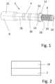
- Figure 1 shows a rod or tube 2 for percussive drilling, comprising a hollow elongate main length section 4 having a longitudinal axis 18 extending axially between a male end 6 at an axially forward end 20 and a female end 8 at an axially rearward end 22 of the rod or tube 2.
- the male end comprises a male connecting means 10 and a radially projecting shoulder 12 that axially separates the main length section 4 and the male connecting means 10.
- the shoulder 12 comprises a peripheral surface 14 that may have a greater outer diameter than the outer diameter of the main length section 4.
- Figure 2 shows that there is a laser cladding layer 16 positioned on at least part of the peripheral surface of the rod or tube 2.
- the laser cladding layer 16 is positioned on at least part of the peripheral surface 14 of the shoulder 12.
- the laser cladding layer 16 is positioned on the entire peripheral surface 14 of the shoulder.
- the laser cladding layer 16 is positioned on an axially rearward side face 24 of the shoulder 12.
- the laser cladding layer 16 is not positioned on the axially forward side face 26, otherwise known as the striking face, of the shoulder 12.
- the laser cladding layer 16 extends over a friction weld 28 which is positioned on the main length section 4.
- the laser cladding layer 16 extends at least 100 mm, preferably at least 200 mm, more preferably at least 300 mm, even more preferably at least 400 mm, most preferably at least 500 mm along the peripheral surface of the rod or tube 2 from the axially rearward side of the shoulder 12.
- the laser cladding layer 16 extends over the male end 6 of the drill rod or tube 2.
- the laser cladding layer 16 extends over the female end 8. It should be understood that the laser cladding layer 16 can be positioned on any combination of the different locations on the rod or tube 2.
- the heat affected zone (HAZ) projecting into surface of the rod or tube 2 where the laser cladding layer 16 has been applied is ⁇ 0.3 mm, preferably ⁇ 0.2 mm, more preferably ⁇ 0.1 mm.
- the thickness of the laser cladding layer 16 is between 20 - 2000 ⁇ m, preferably 20-1000 ⁇ m, more preferably between 25-500 ⁇ m.
- the laser cladding layer 16 could have a substantially uniform thickness in all areas where it is applied or could have different thicknesses in different areas as required.
- the composition of the laser cladding layer 16 comprises a metal matrix composite (MMC).
- MMC comprises a secondary hard phase, for example this could be tungsten carbide, titanium carbide, tantalum carbide, niobium carbide or any other carbide or nitride or a mixture thereof and a metal alloy as a binder which could for example be cobalt, nickel, iron, chromium or a mixture thereof.
- the composition of the laser cladding layer 16 comprises a metal alloy.
- the composition of the laser cladding material could for example be, but not limited to, a stainless steel or tool steel, a nickel-based alloy e.g. a Ni-Cr alloy; an Fe based alloy; a Cr-based alloy; stellite or, inconel a mixture thereof or any other suitable material.
- the material selected can be chosen to suit the specific application and drilling environment, for example stainless steel will provide better corrosion protection, whereas tool steel or hard metal composite will provide better wear resistance.
- the laser cladding layer 16 has a hardness of between 500 to 1800 HV10, preferably between 800 - 1800 HV10, more preferably between 1000 - 1800 HV10. If the cladding layer 16 is a metal matrix composite preferably the hardness of the metal matrix is 500-900 HV10, preferably 600-900 HV10, more preferably 600-900 HV10 and the hardness of the hard metal phase is 1500-3500 HV0.1, preferably 2000-3500 HV0.1 and most preferably 2500-3500 HV0.1.
- the present invention also relates to method of providing wear protection to a drill rod or tube 2 wherein a wear protection layer 16 is applied to at least one part of the peripheral surface of the rod or tube 2 using laser cladding.
- the peripheral or external surface of the rod or tube 2 can also be considered to be the substrate for the laser cladding.
- Laser cladding is a melting process where a laser beam is used to fuse a powder alloy with another metallurgical composition onto a substrate. A metallic substrate is exposed to a laser beam while a powder is injected over the melted bath to form, after being solidified, a layer referred to as the cladding on the surface of the substrate.
- the laser cladding could be applied using any suitable laser.
- the laser cladding is performed using extreme high-speed laser material deposition (EHLA).
- EHLA is a laser cladding method which faster than traditional laser cladding methods in terms of surface coverage rate.
- the high-speed deposition from EHLA does not only result in a faster processing time, it also makes it possible to apply cladding to a substrate with even lower heat input and smaller distortion, meaning that the heat effected zone will be even less in the substrate.
- the small dilution formed by EHLA makes it possible to apply even thinner coatings, the thickness of the laser cladding layers is for example typically only 25-400 ⁇ m thick.
- the drill rod or tube as described hereinbefore or hereinafter may form part of a drill string and / or part of a drill rig assembly.
Landscapes
- Engineering & Computer Science (AREA)
- Life Sciences & Earth Sciences (AREA)
- Geology (AREA)
- Mining & Mineral Resources (AREA)
- Mechanical Engineering (AREA)
- Physics & Mathematics (AREA)
- Environmental & Geological Engineering (AREA)
- Fluid Mechanics (AREA)
- General Life Sciences & Earth Sciences (AREA)
- Geochemistry & Mineralogy (AREA)
- Earth Drilling (AREA)
Abstract
A drill rod or tube comprising a hollow elongate main length section having a longitudinal axis extending axially between a male end at an axially forward end and a female end at an axially rearward end; the male end comprising a male connecting means and a radially projecting shoulder that axially separates the main length section and the male connecting means; the shoulder comprising a peripheral surface that may have a greater outer diameter than the outer diameter of the main length section: wherein at least part of the peripheral surface of the rod or tube has at least one laser cladding layer positioned thereon.
Description
- The present invention relates to a rod or tube for percussive drilling having a laser cladded wear protection layer and a method of producing there said.
- Percussion drill bits are widely used both for drilling relatively shallow bores in hard rock and for creating deep boreholes. For the latter application, drill strings are typically used in which a plurality of rods or tubes are interconnected to advance the drill bit and increase the depth of the hole. In 'top hammer drilling' a terrestrial machine is operative to transfer a combined impact and rotary drive motion to an upper end of the drill string whilst a drill bit positioned at the lower end is operative to crush the rock and form the boreholes.
- Drill rods or tubes, that are connectable to neighbouring drill rods or tubes and the drill bit or guide adapter, can have a shoulder. The shoulder is typically formed as a radially flared extension of the main length section of the drill rod to provide increased efficiency in energy transfer between the drill rod and the drill bit or a guide adapter. The shoulder on the first drill string rod or tube that joins to the drill bit or guide adapter and the shoulder on the guide adapter is exposed to high levels of wear as the hole collapses and rock cuttings gather behind the drill bit. The problem with this is that as the shoulder wears the strength of the coupling will weaken prematurely. Additionally, as the shoulder wears away the contact area between the drill string rod and the drill bit or guide adapter or between the guide adapter and the drill bit decreases and therefore the transfer of the energy between the drill bit or guide adapter and rod or tube, or adjacent rods or tubes decreases, if the transfer of energy is not efficient energy will be wasted and the drilling efficiency will be compromised. This premature failure leads to low service life of the rods or tubes.
- One known solution is to hard face the peripheral edge of the shoulder using FCAW, MIG/MAG or thermal spraying methods, however a problem with these methods can be that excessive heat input will create a large heat affected zone (HAZ). The large HAZ in addition to thick layers can create stresses between the substrate and the cladding thereby leading to cracking. Any cracks formed during the deposition will be a possible initiation point for failure. Therefore, the problem to be solved is how to protect the rod or tube from wear without introducing unwanted stresses.
- It is an objective of the present invention to provide a drill rod or tube having increased wear protection. This objective is achieved by providing a drill rod or tube comprising a hollow elongate main length section having a longitudinal axis extending axially between a male end at an axially forward end and a female end at an axially rearward end; the male end comprising a male connecting means and a radially projecting shoulder that axially separates the main length section and the male connecting means; the shoulder comprising a peripheral surface that may have a greater outer diameter than the outer diameter of the main length section: wherein at least part of the peripheral surface of the rod or tube has at least one laser cladding layer positioned thereon.
- Advantageously, the laser cladding provides wear protection to the rod or tube it is applied to, therefore reducing the risk of premature failure which maintains drilling efficiency and prolongs the lifetime of the rod.
- In one embodiment the laser cladding layer is positioned on at least part of the peripheral surface of the shoulder. Advantageously, this provides protection to the shoulder which is especially prone to wear. It is particularly important to protect the shoulder from wear as if it gets worn down too quickly it will no longer be able to effectively transfer energy to the drill bit or adjacent rod or tube that it is connected to meaning that the drilling efficiency would be decreased and accelerated wear of the drill bit or adjacent coupling will occur. Therefore, increased wear protection to the shoulder results in increased drilling efficiency.
- In one embodiment the laser cladding layer extends at least 100 mm along the peripheral surface of the rod or tube from the axially forward side of the shoulder. Advantageously, this provides wear protection to the area of the rod or tube that is most exposed to wear.
- In one embodiment, the laser cladding layer extends over the male end of the drill rod or tube. Advantageously, this provides wear protection to the male end of the drill rod or tube.
- In one embodiment the laser cladding layer extends over the female end of the drill rod or tube. Advantageously, this provides wear protection to the female end of the drill rod or tube.
- In one embodiment the heat affected zone (HAZ) projecting into surface of the rod or tube where the laser cladding layer has been applied is <0.3 mm. Advantageously, this reduces or removes the build-up of unfavourable stresses between the laser cladding layer and the surface of the rod or tube it has been applied to, otherwise known as the substrate. Therefore, reducing the risk of cracking in the laser cladding layer which would have a detrimental effect on the wear resistance of the protective layer. Any cracking in the laser cladding layer may also propagate into substrate it has been applied to which may have a negative impact on the lifetime of the rod or tube.
- In one embodiment the thickness of the laser cladding layer is between 20 - 2000 µm. Advantageously, this thickness range provides an optimal balance between providing sufficient wear protection without adding unnecessary cost and weight.
- In one embodiment the composition of the laser cladding layer comprises a metal matrix composite (MMC). Advantageously, the use of MMC as the cladding material provides high wear resistance.
- In one embodiment the composition of the laser cladding layer comprises a metal alloy. Advantageously, the metal alloy can be selected to have superior corrosion and /or wear resistance to suit the application.
- In one embodiment the laser cladding layer has a hardness of between 500 to 1800 HV10. Advantageously, this provides increased wear resistance.
- Another aspect of the present application is a method of providing wear protection to a drill rod or tube characterised in that: a wear protection layer is applied to at least one part of the peripheral surface of the rod or tube using laser cladding. Advantageously, the application of a laser cladding layer will increase the wear resistance of the drill rod or tube.
- In one embodiment, the laser cladding is performed using extreme high-speed laser material deposition (EHLA). Advantageously, EHLA coatings can be applied on the substrate with minimum HAZ, thereby reducing the build-up of unfavourable stress between the wear protection layer and the peripheral surface of the rod or tube where the laser cladding has been applied consequently resulting increased wear protection which will increase the lifetime of the rod or tube. Additionally, with the EHLA process it is possible to get a wide range of different properties of the coating depending on what type of powder is selected. EHLA provides thinner layers, with a reduced heat effected zone as the dilution between the cladding and the substrate is smaller, with higher power efficiency and faster processing times.
- A specific implementation of the present invention will now be described, by way of example only, and with reference to the accompanying drawings in which:
-
Figure 1 is a schematic drawing of a drill rod or tube. -
Figure 2 is a schematic drawing of the laser cladding layer. -
Figure 1 shows a rod ortube 2 for percussive drilling, comprising a hollow elongatemain length section 4 having alongitudinal axis 18 extending axially between amale end 6 at an axiallyforward end 20 and afemale end 8 at an axiallyrearward end 22 of the rod ortube 2. The male end comprises a male connecting means 10 and a radially projectingshoulder 12 that axially separates themain length section 4 and the male connecting means 10. Theshoulder 12 comprises aperipheral surface 14 that may have a greater outer diameter than the outer diameter of themain length section 4. -
Figure 2 shows that there is alaser cladding layer 16 positioned on at least part of the peripheral surface of the rod ortube 2. - The
laser cladding layer 16 is positioned on at least part of theperipheral surface 14 of theshoulder 12. Optionally, thelaser cladding layer 16 is positioned on the entireperipheral surface 14 of the shoulder. Optionally, thelaser cladding layer 16 is positioned on an axiallyrearward side face 24 of theshoulder 12. Preferably, thelaser cladding layer 16 is not positioned on the axiallyforward side face 26, otherwise known as the striking face, of theshoulder 12. Optionally, thelaser cladding layer 16 extends over afriction weld 28 which is positioned on themain length section 4. - Optionally, the
laser cladding layer 16 extends at least 100 mm, preferably at least 200 mm, more preferably at least 300 mm, even more preferably at least 400 mm, most preferably at least 500 mm along the peripheral surface of the rod ortube 2 from the axially rearward side of theshoulder 12. - Optionally, the
laser cladding layer 16 extends over themale end 6 of the drill rod ortube 2. Optionally, thelaser cladding layer 16 extends over thefemale end 8. It should be understood that thelaser cladding layer 16 can be positioned on any combination of the different locations on the rod ortube 2. - Preferably, the heat affected zone (HAZ) projecting into surface of the rod or
tube 2 where thelaser cladding layer 16 has been applied, otherwise known as the substrate is <0.3 mm, preferably <0.2 mm, more preferably <0.1 mm. - In one embodiment the thickness of the
laser cladding layer 16 is between 20 - 2000 µm, preferably 20-1000 µm, more preferably between 25-500 µm. Thelaser cladding layer 16 could have a substantially uniform thickness in all areas where it is applied or could have different thicknesses in different areas as required. - In one embodiment the composition of the
laser cladding layer 16 comprises a metal matrix composite (MMC). The MMC comprises a secondary hard phase, for example this could be tungsten carbide, titanium carbide, tantalum carbide, niobium carbide or any other carbide or nitride or a mixture thereof and a metal alloy as a binder which could for example be cobalt, nickel, iron, chromium or a mixture thereof. - Alternatively, the composition of the
laser cladding layer 16 comprises a metal alloy. The composition of the laser cladding material could for example be, but not limited to, a stainless steel or tool steel, a nickel-based alloy e.g. a Ni-Cr alloy; an Fe based alloy; a Cr-based alloy; stellite or, inconel a mixture thereof or any other suitable material. The material selected can be chosen to suit the specific application and drilling environment, for example stainless steel will provide better corrosion protection, whereas tool steel or hard metal composite will provide better wear resistance. - In one embodiment the
laser cladding layer 16 has a hardness of between 500 to 1800 HV10, preferably between 800 - 1800 HV10, more preferably between 1000 - 1800 HV10. If thecladding layer 16 is a metal matrix composite preferably the hardness of the metal matrix is 500-900 HV10, preferably 600-900 HV10, more preferably 600-900 HV10 and the hardness of the hard metal phase is 1500-3500 HV0.1, preferably 2000-3500 HV0.1 and most preferably 2500-3500 HV0.1. - The present invention also relates to method of providing wear protection to a drill rod or
tube 2 wherein awear protection layer 16 is applied to at least one part of the peripheral surface of the rod ortube 2 using laser cladding. The peripheral or external surface of the rod ortube 2 can also be considered to be the substrate for the laser cladding. Laser cladding is a melting process where a laser beam is used to fuse a powder alloy with another metallurgical composition onto a substrate. A metallic substrate is exposed to a laser beam while a powder is injected over the melted bath to form, after being solidified, a layer referred to as the cladding on the surface of the substrate. The laser cladding could be applied using any suitable laser. - Preferably, the laser cladding is performed using extreme high-speed laser material deposition (EHLA). EHLA is a laser cladding method which faster than traditional laser cladding methods in terms of surface coverage rate. The high-speed deposition from EHLA does not only result in a faster processing time, it also makes it possible to apply cladding to a substrate with even lower heat input and smaller distortion, meaning that the heat effected zone will be even less in the substrate. In addition, the small dilution formed by EHLA makes it possible to apply even thinner coatings, the thickness of the laser cladding layers is for example typically only 25-400 µm thick.
- The drill rod or tube as described hereinbefore or hereinafter may form part of a drill string and / or part of a drill rig assembly.
Claims (15)
- A drill rod or tube (2) comprising a hollow elongate main length section (4) having a longitudinal axis (18) extending axially between a male end (6) at an axially forward end (20) and a female end (8) at an axially rearward end (22);the male end (6) comprising a male connecting means (10) and a radially projecting shoulder (12) that axially separates the main length section (4) and the male connecting means (10);the shoulder (12) comprising a peripheral surface (14);characterised in that:
at least part of the peripheral surface of the rod or tube (2) has at least one laser cladding layer (16) positioned thereon. - The drill rod or tube (2) according to claim 1 wherein the laser cladding layer (16) is positioned on at least part of the peripheral surface (14) of the shoulder (12).
- The drill rod or tube (2) according to claim 1 or claim 2 wherein the laser cladding layer (16) extends at least 100 mm along the peripheral surface of the rod or tube (2) from the axially rearward side of the shoulder (12).
- The drill rod or tube (2) according to any of the previous claims wherein the laser cladding layer (16) extends over the male end (6).
- The drill rod or tub (2) according to any of the previous claims wherein the laser cladding layer (16) extends over the female end (8).
- The drill rod or tube (2) according any of the previous claims wherein the heat affected zone (HAZ) projecting into surface of the rod or tube (2) where the laser cladding layer (16) has been applied is <0.3 mm.
- The drill rod or tube (2) according to any of the previous claims wherein the thickness of the laser cladding layer (16) is between 20 - 2000 µm.
- The drill rod or tube (2) according to any of the previous claims wherein the thickness of the laser cladding layer (16) is between 20 - 1000 µm.
- The drill rod or tube (2) according to any of the previous claims wherein the thickness of the laser cladding layer (16) is between 25-500 µm.
- The drill rod or tube (2) according to any of the previous claims wherein the composition of the laser cladding layer (16) comprises a metal matrix composite (MMC).
- The drill rod or tube (2) according to any of claims 1-8 wherein the composition of the laser cladding layer (16) comprises a metal alloy.
- The drill rod or tube (2) according to any of the previous claims wherein the laser cladding layer (16) has a hardness of between 500 to 1800 HV10.
- A method of providing wear protection to a drill rod or tube (2) characterised in that: a wear protection layer (16) is applied to at least one part of the peripheral surface of the rod or tube (2) using laser cladding.
- The method according to claim 13 wherein the laser cladding is performed using extreme high-speed laser material deposition (EHLA).
- The method according to claim 13 or 14 wherein the laser cladding is applied in a thickness of between 20 - 2000 µm.
Priority Applications (2)
| Application Number | Priority Date | Filing Date | Title |
|---|---|---|---|
| EP22182130.9A EP4299875A1 (en) | 2022-06-30 | 2022-06-30 | Laser cladded rods or tubes for percussive drilling |
| PCT/EP2023/067807 WO2024003240A1 (en) | 2022-06-30 | 2023-06-29 | Laser cladded rods or tubes for percussive drilling |
Applications Claiming Priority (1)
| Application Number | Priority Date | Filing Date | Title |
|---|---|---|---|
| EP22182130.9A EP4299875A1 (en) | 2022-06-30 | 2022-06-30 | Laser cladded rods or tubes for percussive drilling |
Publications (1)
| Publication Number | Publication Date |
|---|---|
| EP4299875A1 true EP4299875A1 (en) | 2024-01-03 |
Family
ID=82492605
Family Applications (1)
| Application Number | Title | Priority Date | Filing Date |
|---|---|---|---|
| EP22182130.9A Withdrawn EP4299875A1 (en) | 2022-06-30 | 2022-06-30 | Laser cladded rods or tubes for percussive drilling |
Country Status (2)
| Country | Link |
|---|---|
| EP (1) | EP4299875A1 (en) |
| WO (1) | WO2024003240A1 (en) |
Citations (5)
| Publication number | Priority date | Publication date | Assignee | Title |
|---|---|---|---|---|
| US20010026069A1 (en) * | 2000-03-02 | 2001-10-04 | John Linden | Corrosion-resistant thread joint for percussion drill element and method of achieving such resistance |
| WO2011103551A1 (en) * | 2010-02-22 | 2011-08-25 | Exxonmobil Research And Engineering Company | Coated sleeved oil and gas well production devices |
| US20170312855A1 (en) * | 2014-10-24 | 2017-11-02 | Laserbond Limited | Method and apparatus for cladding a surface of an article |
| US20210156206A1 (en) * | 2019-11-25 | 2021-05-27 | Kondex Corporation | Wear enhancement of hdd drill string components |
| AU2021106799A4 (en) * | 2021-08-20 | 2021-11-18 | Boart Longyear Manufacturing And Distribution Inc. | Drill rods having stabilizers and systems and methods comprising same |
Family Cites Families (2)
| Publication number | Priority date | Publication date | Assignee | Title |
|---|---|---|---|---|
| DE102018114883B4 (en) * | 2018-06-20 | 2020-12-10 | Ponticon Gmbh | Device and method for (high-speed) laser deposition welding |
| KR102870036B1 (en) * | 2019-07-09 | 2025-10-13 | 오를리콘 메트코 (유에스) 아이엔씨. | Iron-based alloys designed for wear and corrosion resistance |
-
2022
- 2022-06-30 EP EP22182130.9A patent/EP4299875A1/en not_active Withdrawn
-
2023
- 2023-06-29 WO PCT/EP2023/067807 patent/WO2024003240A1/en not_active Ceased
Patent Citations (5)
| Publication number | Priority date | Publication date | Assignee | Title |
|---|---|---|---|---|
| US20010026069A1 (en) * | 2000-03-02 | 2001-10-04 | John Linden | Corrosion-resistant thread joint for percussion drill element and method of achieving such resistance |
| WO2011103551A1 (en) * | 2010-02-22 | 2011-08-25 | Exxonmobil Research And Engineering Company | Coated sleeved oil and gas well production devices |
| US20170312855A1 (en) * | 2014-10-24 | 2017-11-02 | Laserbond Limited | Method and apparatus for cladding a surface of an article |
| US20210156206A1 (en) * | 2019-11-25 | 2021-05-27 | Kondex Corporation | Wear enhancement of hdd drill string components |
| AU2021106799A4 (en) * | 2021-08-20 | 2021-11-18 | Boart Longyear Manufacturing And Distribution Inc. | Drill rods having stabilizers and systems and methods comprising same |
Also Published As
| Publication number | Publication date |
|---|---|
| WO2024003240A1 (en) | 2024-01-04 |
Similar Documents
| Publication | Publication Date | Title |
|---|---|---|
| US11370049B2 (en) | Earth-boring tools having particle-matrix composite bodies and methods for welding particle-matrix composite bodies | |
| EP0883733B2 (en) | Shank adapter | |
| EP1788104B1 (en) | Material for producing parts or coatings adapted for high wear and friction-intensive applications, method for producing such a material and a torque-reduction device for use in a drill string made from the material | |
| US4666797A (en) | Wear resistant facings for couplings | |
| US20100071961A1 (en) | Bit leg outer surface processing using friction stir welding (fsw) | |
| EP3209811B1 (en) | Method and apparatus for cladding a surface of an article | |
| US20220176482A1 (en) | Work string tubing connection restoration | |
| CA1195345A (en) | Powder mixtures for wear resistant facings and products produced therefrom | |
| RU2618025C2 (en) | Method for recovery or strengthening of drilling bit cutter pockets, method for forming a drilling bit cutter pocket and drilling bit blades | |
| AU716765B2 (en) | Friction welded drill rod and method for manufacturing the rod | |
| WO2024003240A1 (en) | Laser cladded rods or tubes for percussive drilling | |
| US20170198577A1 (en) | Rotatable Cutting Tool | |
| CN106480450A (en) | A kind of laser melting coating oil drilling tools wear resistant alloy powders material | |
| US12352108B2 (en) | Devices, systems, and methods for a bit including a matrix portion and a steel portion | |
| CN204571998U (en) | A kind of shield machine cutter structure | |
| EP4112869A1 (en) | Laser cladded shank adapter | |
| EP4279704A1 (en) | Nickel based wear and corrosion protected shank adapter | |
| US20170198576A1 (en) | Holder for cutting tool | |
| EP3751092B1 (en) | Guide adapter | |
| KR20220008825A (en) | drill string rod | |
| EP4279705A1 (en) | Double layer wear and corrosion protected shank adapter | |
| US20150259985A1 (en) | Short matrix drill bits and methodologies for manufacturing short matrix drill bits | |
| WO2002058927A1 (en) | Methods for applying wear-reducing material to tool joints | |
| WO2026005663A1 (en) | A drill rod and a method of producing such a drill rod |
Legal Events
| Date | Code | Title | Description |
|---|---|---|---|
| PUAI | Public reference made under article 153(3) epc to a published international application that has entered the european phase |
Free format text: ORIGINAL CODE: 0009012 |
|
| STAA | Information on the status of an ep patent application or granted ep patent |
Free format text: STATUS: THE APPLICATION HAS BEEN PUBLISHED |
|
| AK | Designated contracting states |
Kind code of ref document: A1 Designated state(s): AL AT BE BG CH CY CZ DE DK EE ES FI FR GB GR HR HU IE IS IT LI LT LU LV MC MK MT NL NO PL PT RO RS SE SI SK SM TR |
|
| STAA | Information on the status of an ep patent application or granted ep patent |
Free format text: STATUS: THE APPLICATION HAS BEEN WITHDRAWN |
|
| 18W | Application withdrawn |
Effective date: 20240104 |