EP4299443A1 - System including stowage pouch - Google Patents
System including stowage pouch Download PDFInfo
- Publication number
- EP4299443A1 EP4299443A1 EP23182457.4A EP23182457A EP4299443A1 EP 4299443 A1 EP4299443 A1 EP 4299443A1 EP 23182457 A EP23182457 A EP 23182457A EP 4299443 A1 EP4299443 A1 EP 4299443A1
- Authority
- EP
- European Patent Office
- Prior art keywords
- panel
- seat frame
- aft
- fore
- frame beam
- Prior art date
- Legal status (The legal status is an assumption and is not a legal conclusion. Google has not performed a legal analysis and makes no representation as to the accuracy of the status listed.)
- Granted
Links
Images




Classifications
-
- B—PERFORMING OPERATIONS; TRANSPORTING
- B64—AIRCRAFT; AVIATION; COSMONAUTICS
- B64D—EQUIPMENT FOR FITTING IN OR TO AIRCRAFT; FLIGHT SUITS; PARACHUTES; ARRANGEMENT OR MOUNTING OF POWER PLANTS OR PROPULSION TRANSMISSIONS IN AIRCRAFT
- B64D11/00—Passenger or crew accommodation; Flight-deck installations not otherwise provided for
- B64D11/06—Arrangements of seats, or adaptations or details specially adapted for aircraft seats
- B64D11/0627—Seats combined with storage means
-
- B—PERFORMING OPERATIONS; TRANSPORTING
- B60—VEHICLES IN GENERAL
- B60R—VEHICLES, VEHICLE FITTINGS, OR VEHICLE PARTS, NOT OTHERWISE PROVIDED FOR
- B60R7/00—Stowing or holding appliances inside vehicle primarily intended for personal property smaller than suit-cases, e.g. travelling articles, or maps
- B60R7/04—Stowing or holding appliances inside vehicle primarily intended for personal property smaller than suit-cases, e.g. travelling articles, or maps in driver or passenger space, e.g. using racks
- B60R7/043—Stowing or holding appliances inside vehicle primarily intended for personal property smaller than suit-cases, e.g. travelling articles, or maps in driver or passenger space, e.g. using racks mounted on or under a seat
-
- B—PERFORMING OPERATIONS; TRANSPORTING
- B64—AIRCRAFT; AVIATION; COSMONAUTICS
- B64D—EQUIPMENT FOR FITTING IN OR TO AIRCRAFT; FLIGHT SUITS; PARACHUTES; ARRANGEMENT OR MOUNTING OF POWER PLANTS OR PROPULSION TRANSMISSIONS IN AIRCRAFT
- B64D11/00—Passenger or crew accommodation; Flight-deck installations not otherwise provided for
- B64D11/003—Stowage devices for passengers' personal luggage
-
- B—PERFORMING OPERATIONS; TRANSPORTING
- B60—VEHICLES IN GENERAL
- B60N—SEATS SPECIALLY ADAPTED FOR VEHICLES; VEHICLE PASSENGER ACCOMMODATION NOT OTHERWISE PROVIDED FOR
- B60N2/00—Seats specially adapted for vehicles; Arrangement or mounting of seats in vehicles
- B60N2/68—Seat frames
Definitions
- inventions of the inventive concepts disclosed herein are directed to a system.
- the system includes a seat frame installed in a vehicle.
- the seat frame includes a seat pan, a fore seat frame beam, and an aft seat frame beam, wherein the fore seat frame beam and the aft seat frame beam are under the seat pan, wherein the fore seat frame beam is parallel to the aft seat frame.
- the system includes a pliable stowage pouch accessible by a passenger seated behind the seat frame.
- the pliable stowage pouch includes: an opening located at an aft side of the seat frame; a top panel extending from the opening; an end panel abutting the top panel; a first side panel abutting the top panel and the end panel, the first side panel being elbow-shaped; a second side panel abutting the top panel and the end panel, the second side panel being elbow-shaped; a bottom panel abutting the first side panel, the second side panel, and the end panel; a curved panel extending from the opening toward the bottom panel and abutting the first side panel, the second side panel, and the bottom panel; a closeout flap extending from a top edge of the opening and abutting the top panel, wherein the closeout flap is configured to close the opening in a first state and to open the opening in a second state; aft straps attached to the top panel and secured around the aft seat frame beam; and fore straps attached to the top panel and secured around the fore seat frame beam.
- inventive concepts are not limited in their application to the details of construction and the arrangement of the components or steps or methodologies set forth in the following description or illustrated in the drawings.
- inventive concepts disclosed herein may be practiced without these specific details.
- well-known features may not be described in detail to avoid unnecessarily complicating the instant disclosure.
- inventive concepts disclosed herein are capable of other embodiments or of being practiced or carried out in various ways. Also, it is to be understood that the phraseology and terminology employed herein is for the purpose of description and should not be regarded as limiting.
- a letter following a reference numeral is intended to reference an embodiment of the feature or element that may be similar, but not necessarily identical, to a previously described element or feature bearing the same reference numeral (e.g., 1, 1a, 1b).
- reference numeral e.g. 1, 1a, 1b
- Such shorthand notations are used for purposes of convenience only, and should not be construed to limit the inventive concepts disclosed herein in any way unless expressly stated to the contrary.
- any reference to "one embodiment,” or “some embodiments” means that a particular element, feature, structure, or characteristic described in connection with the embodiment is included in at least one embodiment of the inventive concepts disclosed herein.
- the appearances of the phrase “in some embodiments” in various places in the specification are not necessarily all referring to the same embodiment, and embodiments of the inventive concepts disclosed may include one or more of the features expressly described or inherently present herein, or any combination of sub-combination of two or more such features, along with any other features which may not necessarily be expressly described or inherently present in the instant disclosure.
- embodiments of the inventive concepts disclosed herein are directed to a system including a stowage pouch.
- the stowage pouch may be attached to seat frame beams at an aft side of a seat (e.g., a vehicle seat, such as an aircraft seat, a bus seat, or a train seat).
- a seat e.g., a vehicle seat, such as an aircraft seat, a bus seat, or a train seat.
- Some embodiments may provide more storage space to a passenger seated behind a seat that the stowage pouch is attached to.
- the stowage pouch may be used in economy and premium economy seating's without encroaching any of the passenger comfort space, including leg room.
- the stowage pouch can be attached to seat frame beams, below a seat pan, with the opening facing the aft of the aircraft and to be used by the passenger seating behind the seat installed with the stowage pouch.
- Such pouch may be big enough to act as an additional stowage for the passengers to store their personal belongings.
- the stowage pouch may be made of pliable material (e.g., leather or fabric (e.g., canvas or soft cloth)), instead of rigid thermoform plastic.
- the stowage pouch may be flexible to provide legroom to a passenger that is not impacted due to addition of this feature. Since it's a flexible and/or pliable storage pouch, a passenger can trade-off leg-space comfort verses stowage needs based on their preference and comfort levels. For example, if passenger does not use this additional stowage space, the passenger still has complete leg room as the pliable nature of the pouch allows the passenger to extend their legs. For example, other passengers might use the pouch to store belongings in the middle so that they can stretch their legs on either side of the stowage pouch.
- the stowage pouch uses otherwise unused dead-space to for stowage. Additionally, if the belongings are pushed all the way towards the end of the pouch, the stowage pouch might not take away any of the legroom. The stowage pouch may be big enough to store more belongings of passengers as compared to existing stowage solutions.
- the stowage pouch may include straps secured around the seat frame beams, such as by using buttons, and locations of the buttons may be placed in such a way that the buttons cannot be viewed and accessed by passengers.
- the stowage pouch may include a closeout flap that can be opened and closed by using, e.g., a zipper.
- Some embodiments provide a low cost and low weight solution for improving passenger stowage on aircraft.
- the stowage pouches may have low maintenance costs and may be easily replaceable.
- Some embodiments include straps that are easy to install around seat frame beams by using buttons or any other suitable fastener.
- FIG. 1 an aft perspective view of an exemplary embodiment of a system including a vehicle (e.g., aircraft 100, watercraft, automobile, train, etc.) including at least one seat frame 102 (e.g., an aircraft seat frame) and a pliable stowage pouch 110 is depicted according to the inventive concepts.
- the system may include at least one multiple seat assembly, which may include multiple connected seats that may be installed as a row of seats.
- the seat frame 102 may be installed in a vehicle (e.g., aircraft 100).
- the seat frame 102 may include a seat pan 104, an aft seat frame beam 106, and a fore seat frame beam 108.
- the fore seat frame beam 108 and the aft seat frame beam 106 may be under the seat pan 104.
- the fore seat frame beam 108 may be parallel to the aft seat frame 106.
- the pliable stowage pouch 110 may be accessible by a passenger seated behind the seat frame 102.
- the pliable stowage pouch 110 may include: an opening 112 located at an aft side of the seat frame 102; a top panel 114 extending from the opening 112; an end panel 116 abutting the top panel 114; a first side panel 118 abutting the top panel 114 and the end panel 116, the first side panel 118 being elbow-shaped; a second side panel abutting the top panel 114 and the end panel 116, the second side panel 118 being elbow-shaped; a bottom panel 120 abutting the first side panel 118, the second side panel 118, and the end panel 116; a curved panel 122 extending from the opening 112 toward the bottom panel 120 and abutting the first side panel 118, the second side panel 118, and the bottom panel 120; a closeout flap 128 (as shown in FIGS.
- the closeout flap 128 is configured to close the opening 112 in a first state (e.g., a zipped state) and to open the opening in a second state (e.g., an unzipped state); aft straps 124 attached to the top panel 114 and secured around the aft seat frame beam 106; and/or fore straps 124 attached to the top panel 114 and secured around the fore seat frame beam 108.
- a first state e.g., a zipped state
- a second state e.g., an unzipped state
- the pliable stowage pouch 110 further includes first and second flexible shaping structures 126.
- the first flexible shaping structure 126 may abut the first side panel 118 and extend from the opening 112 along the first side panel 118 toward the bottom panel 120.
- the second flexible shaping structure 126 may abut the second side panel 118 and extend from the opening 112 along the second side panel 118 toward the bottom panel 120.
- each of the first and second flexible shaping structures 126 may be at least composed of a rubber material (e.g., neoprene rubber).
- each of the top panel 114, the end panel 116, the bottom panel 120, the first side panel 118, the second side panel 118, the curved panel 122, and the closeout flap 128 may at least be composed of fabric.
- an angle between the top panel 114 and the end panel 116 may be obtuse. In some embodiments, an angle between the bottom panel 120 and the curved panel 122 may be obtuse. In some embodiments, an angle between the bottom panel 120 and the end panel 116 may be a right angle. In some embodiments, an angle between the bottom panel 120 and the first side panel 118 is a right angle, and an angle between the bottom panel 120 and the second side panel 118 is a right angle. In some embodiments, the aft seat frame beam 106 is higher than the fore seat frame 108.
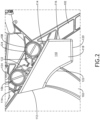
- FIG. 2 a side view of the system including the seat frame 102 and the pliable stowage pouch 110 of FIG. 1 is shown.
- the pliable stowage pouch 110 may include the closeout flap 128 extending from a top edge of the opening 112 and abutting the top panel 114.
- the closeout flap 128 may be configured to close the opening in the first state (e.g., a zipped state) via a zipper 130 extending at least along an edge of the closeout flap 128 and an edge of the curved panel 122.
- the closeout flap 128 may be configured to close the opening 112 in the first state (e.g., a zipped state) via the zipper 130 extending at least along edges of the closeout flap 128 and an edge of the curved panel 122, an edge of the first side panel 118, and an edge of the second side panel.
- the closeout flap 128 may be attached to the top panel 114, such as with stitches, or the closeout flap 128 may be an extension of the top panel 114.
- the closeout flap 128 may be opened at the bottom.
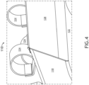
- FIG. 4 another aft side perspective view of an exemplary embodiment of the pliable stowage pouch 110 of FIG. 1 is shown.
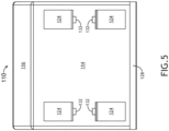
- each of the aft straps 124 and the fore straps 124 may include a strap and a button 132, wherein each button 132 is configured to secure a given strap around one of the fore seat frame beam 108 or the aft seat frame beam 106.
- each of the straps 124 is composed of at least one of plastic, leather, or fabric (e.g., canvas or soft cloth).
- the button 132 of each of the aft straps 124 is positioned on a fore side of the aft seat frame beam 106, and when each of the fore straps 124 are secured around the fore seat frame 108, the button 132 of each of the fore straps 124 is positioned on an aft side of the fore seat frame beam 108; for example, positions of the buttons 132 of the fore straps 124 and the aft straps 124 being in between the fore seat frame beam 108 and the aft seat frame beam 106 may inhibit the passenger seated behind the seat frame 102 from viewing and accessing the buttons 132.
- FIG. 6 an aft perspective view of an exemplary embodiment of the pliable stowage pouch 110 of FIG. 1 is shown.
- FIG. 7 a top perspective view of an exemplary embodiment of the pliable stowage pouch 110 of FIG. 1 is shown.
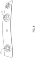
- FIG. 8 a view of an exemplary embodiment of one of the straps 124 of the pliable stowage pouch 110 of FIG. 1 is shown.
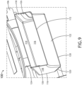
- FIG. 9 an aft side perspective view of an exemplary embodiment of the pliable stowage pouch 110 of FIG. 1 is shown.
- embodiments of the inventive concepts disclosed herein may be directed to a system including a stowage pouch.
- At least one means one or a plurality of; for example, “at least one” may comprise one, two, three, ..., one hundred, or more.
- one or more means one or a plurality of; for example, “one or more” may comprise one, two, three, ..., one hundred, or more.
- zero or more means zero, one, or a plurality of; for example, “zero or more” may comprise zero, one, two, three, ..., one hundred, or more.
- the methods, operations, and/or functionality disclosed may be implemented as sets of instructions or software readable by a device. Further, it is understood that the specific order or hierarchy of steps in the methods, operations, and/or functionality disclosed are examples of exemplary approaches. Based upon design preferences, it is understood that the specific order or hierarchy of steps in the methods, operations, and/or functionality can be rearranged while remaining within the scope of the inventive concepts disclosed herein.
- the accompanying claims may present elements of the various steps in a sample order, and are not necessarily meant to be limited to the specific order or hierarchy presented.
- embodiments of the methods according to the inventive concepts disclosed herein may include one or more of the steps described herein. Further, such steps may be carried out in any desired order and two or more of the steps may be carried out simultaneously with one another. Two or more of the steps disclosed herein may be combined in a single step, and in some embodiments, one or more of the steps may be carried out as two or more sub-steps. Further, other steps or sub-steps may be carried in addition to, or as substitutes to one or more of the steps disclosed herein.
- inventive concepts disclosed herein are well adapted to carry out the objects and to attain the advantages mentioned herein as well as those inherent in the inventive concepts disclosed herein. While presently preferred embodiments of the inventive concepts disclosed herein have been described for purposes of this disclosure, it will be understood that numerous changes may be made which will readily suggest themselves to those skilled in the art and which are accomplished within the broad scope and coverage of the inventive concepts disclosed and claimed herein.
Landscapes
- Engineering & Computer Science (AREA)
- Aviation & Aerospace Engineering (AREA)
- Mechanical Engineering (AREA)
- Seats For Vehicles (AREA)
Abstract
Description
- The present application is related to and claims priority from:
Indian Application Serial Number 202211038223, titled SYSTEM INCLUDING CONNECTOR BRACKET, filed July 2, 2022 - Current aircraft seating, especially economy class, does not provide a desired amount of storage space to the passengers, especially on long haul planes where passengers carry many personal belongings. Currently, the stowage space, typically, is only a literature pocket for the economy seating, which is already occupied with some magazines.
- In one aspect, embodiments of the inventive concepts disclosed herein are directed to a system. The system includes a seat frame installed in a vehicle. The seat frame includes a seat pan, a fore seat frame beam, and an aft seat frame beam, wherein the fore seat frame beam and the aft seat frame beam are under the seat pan, wherein the fore seat frame beam is parallel to the aft seat frame. The system includes a pliable stowage pouch accessible by a passenger seated behind the seat frame. The pliable stowage pouch includes: an opening located at an aft side of the seat frame; a top panel extending from the opening; an end panel abutting the top panel; a first side panel abutting the top panel and the end panel, the first side panel being elbow-shaped; a second side panel abutting the top panel and the end panel, the second side panel being elbow-shaped; a bottom panel abutting the first side panel, the second side panel, and the end panel; a curved panel extending from the opening toward the bottom panel and abutting the first side panel, the second side panel, and the bottom panel; a closeout flap extending from a top edge of the opening and abutting the top panel, wherein the closeout flap is configured to close the opening in a first state and to open the opening in a second state; aft straps attached to the top panel and secured around the aft seat frame beam; and fore straps attached to the top panel and secured around the fore seat frame beam.
- Implementations of the inventive concepts disclosed herein may be better understood when consideration is given to the following detailed description thereof. Such description makes reference to the included drawings, which are not necessarily to scale, and in which some features may be exaggerated and some features may be omitted or may be represented schematically in the interest of clarity. Like reference numerals in the drawings may represent and refer to the same or similar element, feature, or function. In the drawings:
-
FIG. 1 is an aft side perspective view of an exemplary embodiment of a system including a vehicle including a seat frame and a pliable stowage pouch according to the inventive concepts disclosed herein. -
FIG. 2 is a side view of an exemplary embodiment of the seat frame and the pliable stowage pouch ofFIG. 1 according to the inventive concepts disclosed herein. -
FIG. 3 is an aft side perspective view of the pliable stowage pouch ofFIG. 1 according to the inventive concepts disclosed herein. -
FIG. 4 is another aft side perspective view of the pliable stowage pouch ofFIG. 1 according to the inventive concepts disclosed herein. -
FIG. 5 is top side view of the pliable stowage pouch ofFIG. 1 according to the inventive concepts disclosed herein. -
FIG. 6 is another view of the pliable stowage pouch ofFIG. 1 according to the inventive concepts disclosed herein. -
FIG. 7 is another view of the pliable stowage pouch ofFIG. 1 according to the inventive concepts disclosed herein. -
FIG. 8 is a view an exemplary embodiment of a strap of the pliable stowage pouch ofFIG. 1 according to the inventive concepts disclosed herein. -
FIG. 9 is another aft side perspective view of an exemplary embodiment of the seat frame and the pliable stowage pouch ofFIG. 1 according to the inventive concepts disclosed herein. - Before explaining at least one embodiment of the inventive concepts disclosed herein in detail, it is to be understood that the inventive concepts are not limited in their application to the details of construction and the arrangement of the components or steps or methodologies set forth in the following description or illustrated in the drawings. In the following detailed description of embodiments of the instant inventive concepts, numerous specific details are set forth in order to provide a more thorough understanding of the inventive concepts. However, it will be apparent to one of ordinary skill in the art having the benefit of the instant disclosure that the inventive concepts disclosed herein may be practiced without these specific details. In other instances, well-known features may not be described in detail to avoid unnecessarily complicating the instant disclosure. The inventive concepts disclosed herein are capable of other embodiments or of being practiced or carried out in various ways. Also, it is to be understood that the phraseology and terminology employed herein is for the purpose of description and should not be regarded as limiting.
- As used herein a letter following a reference numeral is intended to reference an embodiment of the feature or element that may be similar, but not necessarily identical, to a previously described element or feature bearing the same reference numeral (e.g., 1, 1a, 1b). Such shorthand notations are used for purposes of convenience only, and should not be construed to limit the inventive concepts disclosed herein in any way unless expressly stated to the contrary.
- Further, unless expressly stated to the contrary, "or" refers to an inclusive or and not to an exclusive or. For example, a condition A or B is satisfied by anyone of the following: A is true (or present) and B is false (or not present), A is false (or not present) and B is true (or present), and both A and B are true (or present).
- In addition, use of the "a" or "an" are employed to describe elements and components of embodiments of the instant inventive concepts. This is done merely for convenience and to give a general sense of the inventive concepts, and "a" and "an" are intended to include one or at least one and the singular also includes the plural unless it is obvious that it is meant otherwise.
- Finally, as used herein any reference to "one embodiment," or "some embodiments" means that a particular element, feature, structure, or characteristic described in connection with the embodiment is included in at least one embodiment of the inventive concepts disclosed herein. The appearances of the phrase "in some embodiments" in various places in the specification are not necessarily all referring to the same embodiment, and embodiments of the inventive concepts disclosed may include one or more of the features expressly described or inherently present herein, or any combination of sub-combination of two or more such features, along with any other features which may not necessarily be expressly described or inherently present in the instant disclosure.
- Broadly, embodiments of the inventive concepts disclosed herein are directed to a system including a stowage pouch.
- In some embodiments, the stowage pouch may be attached to seat frame beams at an aft side of a seat (e.g., a vehicle seat, such as an aircraft seat, a bus seat, or a train seat).
- Some embodiments may provide more storage space to a passenger seated behind a seat that the stowage pouch is attached to. For example, the stowage pouch may be used in economy and premium economy seating's without encroaching any of the passenger comfort space, including leg room. The stowage pouch can be attached to seat frame beams, below a seat pan, with the opening facing the aft of the aircraft and to be used by the passenger seating behind the seat installed with the stowage pouch. Such pouch may be big enough to act as an additional stowage for the passengers to store their personal belongings. Some embodiments solve the problem of current seating that does not currently provide enough storage space to the passengers, especially on long-haul planes where passengers carry many personal belongings.
- In some embodiments, the stowage pouch may be made of pliable material (e.g., leather or fabric (e.g., canvas or soft cloth)), instead of rigid thermoform plastic. As such, the stowage pouch may be flexible to provide legroom to a passenger that is not impacted due to addition of this feature. Since it's a flexible and/or pliable storage pouch, a passenger can trade-off leg-space comfort verses stowage needs based on their preference and comfort levels. For example, if passenger does not use this additional stowage space, the passenger still has complete leg room as the pliable nature of the pouch allows the passenger to extend their legs. For example, other passengers might use the pouch to store belongings in the middle so that they can stretch their legs on either side of the stowage pouch.
- In some embodiments, the stowage pouch uses otherwise unused dead-space to for stowage. Additionally, if the belongings are pushed all the way towards the end of the pouch, the stowage pouch might not take away any of the legroom. The stowage pouch may be big enough to store more belongings of passengers as compared to existing stowage solutions.
- In some embodiments, the stowage pouch may include straps secured around the seat frame beams, such as by using buttons, and locations of the buttons may be placed in such a way that the buttons cannot be viewed and accessed by passengers.
- In some embodiments, the stowage pouch may include a closeout flap that can be opened and closed by using, e.g., a zipper.
- Some embodiments provide a low cost and low weight solution for improving passenger stowage on aircraft. The stowage pouches may have low maintenance costs and may be easily replaceable. Some embodiments include straps that are easy to install around seat frame beams by using buttons or any other suitable fastener.
- Referring now to
FIG. 1 , an aft perspective view of an exemplary embodiment of a system including a vehicle (e.g.,aircraft 100, watercraft, automobile, train, etc.) including at least one seat frame 102 (e.g., an aircraft seat frame) and apliable stowage pouch 110 is depicted according to the inventive concepts. In some embodiments, the system may include at least one multiple seat assembly, which may include multiple connected seats that may be installed as a row of seats. - The
seat frame 102 may be installed in a vehicle (e.g., aircraft 100). Theseat frame 102 may include aseat pan 104, an aftseat frame beam 106, and a foreseat frame beam 108. The foreseat frame beam 108 and the aftseat frame beam 106 may be under theseat pan 104. The foreseat frame beam 108 may be parallel to theaft seat frame 106. - The
pliable stowage pouch 110 may be accessible by a passenger seated behind theseat frame 102. The pliable stowage pouch 110 may include: an opening 112 located at an aft side of the seat frame 102; a top panel 114 extending from the opening 112; an end panel 116 abutting the top panel 114; a first side panel 118 abutting the top panel 114 and the end panel 116, the first side panel 118 being elbow-shaped; a second side panel abutting the top panel 114 and the end panel 116, the second side panel 118 being elbow-shaped; a bottom panel 120 abutting the first side panel 118, the second side panel 118, and the end panel 116; a curved panel 122 extending from the opening 112 toward the bottom panel 120 and abutting the first side panel 118, the second side panel 118, and the bottom panel 120; a closeout flap 128 (as shown inFIGS. 3 ,4 , and6 ) extending from a top edge of the opening 112 and abutting the top panel 114, wherein the closeout flap 128 is configured to close the opening 112 in a first state (e.g., a zipped state) and to open the opening in a second state (e.g., an unzipped state); aft straps 124 attached to the top panel 114 and secured around the aft seat frame beam 106; and/or fore straps 124 attached to the top panel 114 and secured around the fore seat frame beam 108. - In some embodiments, the
pliable stowage pouch 110 further includes first and secondflexible shaping structures 126. The firstflexible shaping structure 126 may abut thefirst side panel 118 and extend from theopening 112 along thefirst side panel 118 toward thebottom panel 120. The secondflexible shaping structure 126 may abut thesecond side panel 118 and extend from theopening 112 along thesecond side panel 118 toward thebottom panel 120. In some embodiments, each of the first and secondflexible shaping structures 126 may be at least composed of a rubber material (e.g., neoprene rubber). - In some embodiments, each of the
top panel 114, theend panel 116, thebottom panel 120, thefirst side panel 118, thesecond side panel 118, thecurved panel 122, and thecloseout flap 128 may at least be composed of fabric. - In some embodiments, an angle between the
top panel 114 and theend panel 116 may be obtuse. In some embodiments, an angle between thebottom panel 120 and thecurved panel 122 may be obtuse. In some embodiments, an angle between thebottom panel 120 and theend panel 116 may be a right angle. In some embodiments, an angle between thebottom panel 120 and thefirst side panel 118 is a right angle, and an angle between thebottom panel 120 and thesecond side panel 118 is a right angle. In some embodiments, the aftseat frame beam 106 is higher than thefore seat frame 108. - Referring now to
FIG. 2 , a side view of the system including theseat frame 102 and thepliable stowage pouch 110 ofFIG. 1 is shown. - Referring now to
FIG. 3 , an aft side perspective view of an exemplary embodiment of thepliable stowage pouch 110 ofFIG. 1 is shown. As shown inFIG. 3 , thepliable stowage pouch 110 may include thecloseout flap 128 extending from a top edge of theopening 112 and abutting thetop panel 114. In some embodiments, thecloseout flap 128 may be configured to close the opening in the first state (e.g., a zipped state) via azipper 130 extending at least along an edge of thecloseout flap 128 and an edge of thecurved panel 122. In some embodiments, thecloseout flap 128 may be configured to close theopening 112 in the first state (e.g., a zipped state) via thezipper 130 extending at least along edges of thecloseout flap 128 and an edge of thecurved panel 122, an edge of thefirst side panel 118, and an edge of the second side panel. In some embodiments, thecloseout flap 128 may be attached to thetop panel 114, such as with stitches, or thecloseout flap 128 may be an extension of thetop panel 114. Thecloseout flap 128 may be opened at the bottom. - Referring now to
FIG. 4 , another aft side perspective view of an exemplary embodiment of thepliable stowage pouch 110 ofFIG. 1 is shown. - Referring now to
FIG. 5 , a top side view of an exemplary embodiment of thepliable stowage pouch 110 ofFIG. 1 is shown. In some embodiments, each of theaft straps 124 and the fore straps 124 may include a strap and abutton 132, wherein eachbutton 132 is configured to secure a given strap around one of the foreseat frame beam 108 or the aftseat frame beam 106. In some embodiments, each of thestraps 124 is composed of at least one of plastic, leather, or fabric (e.g., canvas or soft cloth). In some embodiments, when each of theaft straps 124 are secured around the aftseat frame beam 106, thebutton 132 of each of theaft straps 124 is positioned on a fore side of the aftseat frame beam 106, and when each of the fore straps 124 are secured around thefore seat frame 108, thebutton 132 of each of the fore straps 124 is positioned on an aft side of the foreseat frame beam 108; for example, positions of thebuttons 132 of thefore straps 124 and theaft straps 124 being in between the foreseat frame beam 108 and the aftseat frame beam 106 may inhibit the passenger seated behind theseat frame 102 from viewing and accessing thebuttons 132. - Referring now to
FIG. 6 , an aft perspective view of an exemplary embodiment of thepliable stowage pouch 110 ofFIG. 1 is shown. - Referring now to
FIG. 7 , a top perspective view of an exemplary embodiment of thepliable stowage pouch 110 ofFIG. 1 is shown. - Referring now to
FIG. 8 , a view of an exemplary embodiment of one of thestraps 124 of thepliable stowage pouch 110 ofFIG. 1 is shown. - Referring now to
FIG. 9 , an aft side perspective view of an exemplary embodiment of thepliable stowage pouch 110 ofFIG. 1 is shown. - As will be appreciated from the above, embodiments of the inventive concepts disclosed herein may be directed to a system including a stowage pouch.
- As used throughout, "at least one" means one or a plurality of; for example, "at least one" may comprise one, two, three, ..., one hundred, or more. Similarly, as used throughout, "one or more" means one or a plurality of; for example, "one or more" may comprise one, two, three, ..., one hundred, or more. Further, as used throughout, "zero or more" means zero, one, or a plurality of; for example, "zero or more" may comprise zero, one, two, three, ..., one hundred, or more.
- In the present disclosure, the methods, operations, and/or functionality disclosed may be implemented as sets of instructions or software readable by a device. Further, it is understood that the specific order or hierarchy of steps in the methods, operations, and/or functionality disclosed are examples of exemplary approaches. Based upon design preferences, it is understood that the specific order or hierarchy of steps in the methods, operations, and/or functionality can be rearranged while remaining within the scope of the inventive concepts disclosed herein. The accompanying claims may present elements of the various steps in a sample order, and are not necessarily meant to be limited to the specific order or hierarchy presented.
- It is to be understood that embodiments of the methods according to the inventive concepts disclosed herein may include one or more of the steps described herein. Further, such steps may be carried out in any desired order and two or more of the steps may be carried out simultaneously with one another. Two or more of the steps disclosed herein may be combined in a single step, and in some embodiments, one or more of the steps may be carried out as two or more sub-steps. Further, other steps or sub-steps may be carried in addition to, or as substitutes to one or more of the steps disclosed herein.
- From the above description, it is clear that the inventive concepts disclosed herein are well adapted to carry out the objects and to attain the advantages mentioned herein as well as those inherent in the inventive concepts disclosed herein. While presently preferred embodiments of the inventive concepts disclosed herein have been described for purposes of this disclosure, it will be understood that numerous changes may be made which will readily suggest themselves to those skilled in the art and which are accomplished within the broad scope and coverage of the inventive concepts disclosed and claimed herein.
Claims (14)
- A system, comprising:a seat frame (102) installed in a vehicle, the seat frame comprising a seat pan (104), a fore seat frame beam (108), and an aft seat frame beam (106), wherein the fore seat frame beam and the aft seat frame beam are under the seat pan, wherein the fore seat frame beam is parallel to the aft seat frame; anda pliable stowage pouch (110) accessible by a passenger seated behind the seat frame, comprising:an opening (112) located at an aft side of the seat frame;a top panel (114) extending from the opening;an end panel (116) abutting the top panel;a first side panel (118) abutting the top panel and the end panel, the first side panel being elbow-shaped;a second side panel (118) abutting the top panel and the end panel, the second side panel being elbow-shaped;a bottom panel (120) abutting the first side panel, the second side panel, and the end panel;a curved panel (122) extending from the opening toward the bottom panel and abutting the first side panel, the second side panel, and the bottom panel;a closeout flap (128) extending from a top edge of the opening and abutting the top panel, wherein the closeout flap is configured to close the opening in a first state and to open the opening in a second state;aft straps (124) attached to the top panel and secured around the aft seat frame beam; andfore straps (124) attached to the top panel and secured around the fore seat frame beam.
- The system of claim 1, wherein the closeout flap (128) is configured to close the opening in the first state via a zipper (130) extending at least along an edge of the closeout flap and an edge of the curved panel.
- The system of claim 2, wherein the closeout flap (128) is configured to close the opening in the first state via a zipper (130) extending at least along edges of the closeout flap and an edge of the curved panel, an edge of the first side panel, and an edge of the second side panel.
- The system of any preceding claim, wherein the pliable stowage pouch (110) further comprises first and second flexible shaping structures (126), the first flexible shaping structure abutting the first side panel (118) and extending from the opening (112) along the first side panel toward the bottom panel (120), the second flexible shaping structure abutting the second side panel (118) and extending from the opening along the second side panel toward the bottom panel.
- The system of claim 4, wherein each of the first and second flexible shaping structures (126) are at least composed of a rubber material.
- The system of claim 5, wherein the rubber material is neoprene rubber.
- The system of any preceding claim, wherein each of the aft straps (124) and the fore straps (124) comprises a strap and a button (132), wherein each button is configured to secure a given strap around one of the fore seat frame beam (108) or the aft seat frame beam (106).
- The system of claim 7, wherein each of the straps is composed of at least one of plastic, leather, or fabric.
- The system of claim 7 or 8, wherein when each of the aft straps (124) are secured around the aft seat frame beam (106), the button (132) of each of the aft straps is positioned on a fore side of the aft seat frame beam (106), wherein when each of the fore straps are secured around the fore seat frame, the button (132) of each of the fore straps is positioned on an aft side of the fore seat frame beam.
- The system of claim 9, wherein positions of the buttons (132) of the fore straps (124) and the aft straps (124) being in between the fore seat frame beam (108) and the aft seat frame beam (106) inhibits the passenger seated behind the seat frame from viewing and accessing the buttons.
- The system of any preceding claim, wherein each of the top panel (114), the end panel (116), the bottom panel (120), the first side panel (118), the second side panel (118), the curved panel (122), and the closeout flap (128) is at least composed of fabric.
- The system of any preceding claim, wherein an angle between the top panel (114) and the end panel (116) is obtuse.
- The system of any preceding claim, wherein an angle between the bottom panel (120) and the curved panel (122) is obtuse
- The system of any preceding claim, wherein an angle between the bottom panel (120) and the end panel (116) is a right angle; and/orwherein an angle between the bottom panel (120) and the first side panel (118) is a right angle, wherein an angle between the bottom panel and the second side panel (118) is a right angle; and/orwherein the aft seat frame beam (106) is higher than the fore seat frame beam. 15. The system of any preceding claim, wherein the vehicle is an aircraft.
Applications Claiming Priority (2)
| Application Number | Priority Date | Filing Date | Title |
|---|---|---|---|
| IN202211038223 | 2022-07-02 | ||
| US18/135,392 US12286231B2 (en) | 2022-07-02 | 2023-04-17 | System including stowage pouch |
Publications (2)
| Publication Number | Publication Date |
|---|---|
| EP4299443A1 true EP4299443A1 (en) | 2024-01-03 |
| EP4299443B1 EP4299443B1 (en) | 2025-09-10 |
Family
ID=87060274
Family Applications (1)
| Application Number | Title | Priority Date | Filing Date |
|---|---|---|---|
| EP23182457.4A Active EP4299443B1 (en) | 2022-07-02 | 2023-06-29 | System including stowage pouch |
Country Status (1)
| Country | Link |
|---|---|
| EP (1) | EP4299443B1 (en) |
Citations (3)
| Publication number | Priority date | Publication date | Assignee | Title |
|---|---|---|---|---|
| US20070152480A1 (en) * | 2005-12-29 | 2007-07-05 | Airbus Deutschland Gmbh | Luggage Retention Device and Seat with Such a Luggage Retention Device |
| US20170246972A1 (en) * | 2012-01-17 | 2017-08-31 | Zodiac Seats Us Llc | Passenger seat |
| CN108583374A (en) * | 2018-05-21 | 2018-09-28 | 常州信息职业技术学院 | Multifunctional bus corrects seat |
-
2023
- 2023-06-29 EP EP23182457.4A patent/EP4299443B1/en active Active
Patent Citations (3)
| Publication number | Priority date | Publication date | Assignee | Title |
|---|---|---|---|---|
| US20070152480A1 (en) * | 2005-12-29 | 2007-07-05 | Airbus Deutschland Gmbh | Luggage Retention Device and Seat with Such a Luggage Retention Device |
| US20170246972A1 (en) * | 2012-01-17 | 2017-08-31 | Zodiac Seats Us Llc | Passenger seat |
| CN108583374A (en) * | 2018-05-21 | 2018-09-28 | 常州信息职业技术学院 | Multifunctional bus corrects seat |
Also Published As
| Publication number | Publication date |
|---|---|
| EP4299443B1 (en) | 2025-09-10 |
Similar Documents
| Publication | Publication Date | Title |
|---|---|---|
| US11046437B2 (en) | Forward-facing aircraft passenger suite with all aisle access | |
| EP3572325B1 (en) | Deployable partition systems and methods for seat assemblies | |
| US10370106B2 (en) | Contoured class divider | |
| EP2230178B1 (en) | Lightweight aircraft passenger seat with composite construction | |
| EP2872398B1 (en) | Class dividing passenger seat bulkhead | |
| US20210206494A1 (en) | Removable modular privacy assembly | |
| US10494102B2 (en) | Seat module comprising a tray table with an optimised design | |
| US12420931B2 (en) | Tray table with integrated stowage pouch for travel essentials | |
| US8814088B2 (en) | Aircraft class divider | |
| US20180022457A1 (en) | Contoured class divider | |
| CN105480156B (en) | Baffle assembly reaches vehicle including this baffle assembly | |
| US20190344896A1 (en) | Seat assembly having a deployable headrest | |
| US7770845B2 (en) | Double module for aircraft passenger(s) | |
| US12286231B2 (en) | System including stowage pouch | |
| EP4299443B1 (en) | System including stowage pouch | |
| US12071245B2 (en) | Dual purpose legrest for a multiple passenger side facing aircraft seat | |
| EP3514064B1 (en) | Aircraft passenger seat extended armrest | |
| US20210323677A1 (en) | Aircraft seat bottom cushion assembly with power providing device | |
| EP4253240B1 (en) | Springless dress cover and lower closeout system for passenger seat | |
| US12600480B2 (en) | Vehicle passenger seat assembly | |
| US10322809B2 (en) | Molded sidewall armrest between fuselage frame bays | |
| US20200245772A1 (en) | Convertible seating unit and seating arrangement | |
| EP4446223A1 (en) | Tray table with integrated stowage pouch for travel essentials | |
| US20250100437A1 (en) | Beverage container holder for use during taxi, takeoff, and landing of an aircraft | |
| EP3939887B1 (en) | Passenger seat dress cover with integrated adjustable lumbar support device |
Legal Events
| Date | Code | Title | Description |
|---|---|---|---|
| PUAI | Public reference made under article 153(3) epc to a published international application that has entered the european phase |
Free format text: ORIGINAL CODE: 0009012 |
|
| STAA | Information on the status of an ep patent application or granted ep patent |
Free format text: STATUS: THE APPLICATION HAS BEEN PUBLISHED |
|
| AK | Designated contracting states |
Kind code of ref document: A1 Designated state(s): AL AT BE BG CH CY CZ DE DK EE ES FI FR GB GR HR HU IE IS IT LI LT LU LV MC ME MK MT NL NO PL PT RO RS SE SI SK SM TR |
|
| STAA | Information on the status of an ep patent application or granted ep patent |
Free format text: STATUS: REQUEST FOR EXAMINATION WAS MADE |
|
| 17P | Request for examination filed |
Effective date: 20240701 |
|
| RBV | Designated contracting states (corrected) |
Designated state(s): AL AT BE BG CH CY CZ DE DK EE ES FI FR GB GR HR HU IE IS IT LI LT LU LV MC ME MK MT NL NO PL PT RO RS SE SI SK SM TR |
|
| GRAP | Despatch of communication of intention to grant a patent |
Free format text: ORIGINAL CODE: EPIDOSNIGR1 |
|
| STAA | Information on the status of an ep patent application or granted ep patent |
Free format text: STATUS: GRANT OF PATENT IS INTENDED |
|
| RIC1 | Information provided on ipc code assigned before grant |
Ipc: B64D 11/00 20060101ALI20250321BHEP Ipc: B60R 7/04 20060101ALI20250321BHEP Ipc: B64D 11/06 20060101AFI20250321BHEP |
|
| INTG | Intention to grant announced |
Effective date: 20250416 |
|
| GRAS | Grant fee paid |
Free format text: ORIGINAL CODE: EPIDOSNIGR3 |
|
| GRAA | (expected) grant |
Free format text: ORIGINAL CODE: 0009210 |
|
| STAA | Information on the status of an ep patent application or granted ep patent |
Free format text: STATUS: THE PATENT HAS BEEN GRANTED |
|
| AK | Designated contracting states |
Kind code of ref document: B1 Designated state(s): AL AT BE BG CH CY CZ DE DK EE ES FI FR GB GR HR HU IE IS IT LI LT LU LV MC ME MK MT NL NO PL PT RO RS SE SI SK SM TR |
|
| REG | Reference to a national code |
Ref country code: GB Ref legal event code: FG4D |
|
| REG | Reference to a national code |
Ref country code: CH Ref legal event code: EP |
|
| REG | Reference to a national code |
Ref country code: DE Ref legal event code: R096 Ref document number: 602023006500 Country of ref document: DE |
|
| REG | Reference to a national code |
Ref country code: IE Ref legal event code: FG4D |
|
| PG25 | Lapsed in a contracting state [announced via postgrant information from national office to epo] |
Ref country code: NO Free format text: LAPSE BECAUSE OF FAILURE TO SUBMIT A TRANSLATION OF THE DESCRIPTION OR TO PAY THE FEE WITHIN THE PRESCRIBED TIME-LIMIT Effective date: 20251210 |
|
| REG | Reference to a national code |
Ref country code: LT Ref legal event code: MG9D |
|
| PG25 | Lapsed in a contracting state [announced via postgrant information from national office to epo] |
Ref country code: FI Free format text: LAPSE BECAUSE OF FAILURE TO SUBMIT A TRANSLATION OF THE DESCRIPTION OR TO PAY THE FEE WITHIN THE PRESCRIBED TIME-LIMIT Effective date: 20250910 |
|
| REG | Reference to a national code |
Ref country code: NL Ref legal event code: MP Effective date: 20250910 |
|
| PG25 | Lapsed in a contracting state [announced via postgrant information from national office to epo] |
Ref country code: HR Free format text: LAPSE BECAUSE OF FAILURE TO SUBMIT A TRANSLATION OF THE DESCRIPTION OR TO PAY THE FEE WITHIN THE PRESCRIBED TIME-LIMIT Effective date: 20250910 |
|
| PG25 | Lapsed in a contracting state [announced via postgrant information from national office to epo] |
Ref country code: GR Free format text: LAPSE BECAUSE OF FAILURE TO SUBMIT A TRANSLATION OF THE DESCRIPTION OR TO PAY THE FEE WITHIN THE PRESCRIBED TIME-LIMIT Effective date: 20251211 |
|
| PG25 | Lapsed in a contracting state [announced via postgrant information from national office to epo] |
Ref country code: SE Free format text: LAPSE BECAUSE OF FAILURE TO SUBMIT A TRANSLATION OF THE DESCRIPTION OR TO PAY THE FEE WITHIN THE PRESCRIBED TIME-LIMIT Effective date: 20250910 |
|
| PG25 | Lapsed in a contracting state [announced via postgrant information from national office to epo] |
Ref country code: LV Free format text: LAPSE BECAUSE OF FAILURE TO SUBMIT A TRANSLATION OF THE DESCRIPTION OR TO PAY THE FEE WITHIN THE PRESCRIBED TIME-LIMIT Effective date: 20250910 |
|
| PG25 | Lapsed in a contracting state [announced via postgrant information from national office to epo] |
Ref country code: BG Free format text: LAPSE BECAUSE OF FAILURE TO SUBMIT A TRANSLATION OF THE DESCRIPTION OR TO PAY THE FEE WITHIN THE PRESCRIBED TIME-LIMIT Effective date: 20250910 Ref country code: PL Free format text: LAPSE BECAUSE OF FAILURE TO SUBMIT A TRANSLATION OF THE DESCRIPTION OR TO PAY THE FEE WITHIN THE PRESCRIBED TIME-LIMIT Effective date: 20250910 |
|
| PG25 | Lapsed in a contracting state [announced via postgrant information from national office to epo] |
Ref country code: RS Free format text: LAPSE BECAUSE OF FAILURE TO SUBMIT A TRANSLATION OF THE DESCRIPTION OR TO PAY THE FEE WITHIN THE PRESCRIBED TIME-LIMIT Effective date: 20251210 |
|
| PG25 | Lapsed in a contracting state [announced via postgrant information from national office to epo] |
Ref country code: ES Free format text: LAPSE BECAUSE OF FAILURE TO SUBMIT A TRANSLATION OF THE DESCRIPTION OR TO PAY THE FEE WITHIN THE PRESCRIBED TIME-LIMIT Effective date: 20250910 |
|
| REG | Reference to a national code |
Ref country code: AT Ref legal event code: MK05 Ref document number: 1835669 Country of ref document: AT Kind code of ref document: T Effective date: 20250910 |
|
| PG25 | Lapsed in a contracting state [announced via postgrant information from national office to epo] |
Ref country code: NL Free format text: LAPSE BECAUSE OF FAILURE TO SUBMIT A TRANSLATION OF THE DESCRIPTION OR TO PAY THE FEE WITHIN THE PRESCRIBED TIME-LIMIT Effective date: 20250910 |
|
| PG25 | Lapsed in a contracting state [announced via postgrant information from national office to epo] |
Ref country code: SM Free format text: LAPSE BECAUSE OF FAILURE TO SUBMIT A TRANSLATION OF THE DESCRIPTION OR TO PAY THE FEE WITHIN THE PRESCRIBED TIME-LIMIT Effective date: 20250910 |
|
| PG25 | Lapsed in a contracting state [announced via postgrant information from national office to epo] |
Ref country code: AT Free format text: LAPSE BECAUSE OF FAILURE TO SUBMIT A TRANSLATION OF THE DESCRIPTION OR TO PAY THE FEE WITHIN THE PRESCRIBED TIME-LIMIT Effective date: 20250910 |
|
| PG25 | Lapsed in a contracting state [announced via postgrant information from national office to epo] |
Ref country code: IT Free format text: LAPSE BECAUSE OF FAILURE TO SUBMIT A TRANSLATION OF THE DESCRIPTION OR TO PAY THE FEE WITHIN THE PRESCRIBED TIME-LIMIT Effective date: 20250910 |
|
| PG25 | Lapsed in a contracting state [announced via postgrant information from national office to epo] |
Ref country code: IS Free format text: LAPSE BECAUSE OF FAILURE TO SUBMIT A TRANSLATION OF THE DESCRIPTION OR TO PAY THE FEE WITHIN THE PRESCRIBED TIME-LIMIT Effective date: 20260110 |
|
| PG25 | Lapsed in a contracting state [announced via postgrant information from national office to epo] |
Ref country code: PT Free format text: LAPSE BECAUSE OF FAILURE TO SUBMIT A TRANSLATION OF THE DESCRIPTION OR TO PAY THE FEE WITHIN THE PRESCRIBED TIME-LIMIT Effective date: 20260112 Ref country code: CZ Free format text: LAPSE BECAUSE OF FAILURE TO SUBMIT A TRANSLATION OF THE DESCRIPTION OR TO PAY THE FEE WITHIN THE PRESCRIBED TIME-LIMIT Effective date: 20250910 |
|
| PG25 | Lapsed in a contracting state [announced via postgrant information from national office to epo] |
Ref country code: EE Free format text: LAPSE BECAUSE OF FAILURE TO SUBMIT A TRANSLATION OF THE DESCRIPTION OR TO PAY THE FEE WITHIN THE PRESCRIBED TIME-LIMIT Effective date: 20250910 Ref country code: SK Free format text: LAPSE BECAUSE OF FAILURE TO SUBMIT A TRANSLATION OF THE DESCRIPTION OR TO PAY THE FEE WITHIN THE PRESCRIBED TIME-LIMIT Effective date: 20250910 |