EP4299434A1 - Propulsion device for marine vessel, outboard motor and marine vessel - Google Patents
Propulsion device for marine vessel, outboard motor and marine vessel Download PDFInfo
- Publication number
- EP4299434A1 EP4299434A1 EP23179523.8A EP23179523A EP4299434A1 EP 4299434 A1 EP4299434 A1 EP 4299434A1 EP 23179523 A EP23179523 A EP 23179523A EP 4299434 A1 EP4299434 A1 EP 4299434A1
- Authority
- EP
- European Patent Office
- Prior art keywords
- shaft
- marine vessel
- propulsion device
- propeller shaft
- central axis
- Prior art date
- Legal status (The legal status is an assumption and is not a legal conclusion. Google has not performed a legal analysis and makes no representation as to the accuracy of the status listed.)
- Granted
Links
Images



Classifications
-
- B—PERFORMING OPERATIONS; TRANSPORTING
- B63—SHIPS OR OTHER WATERBORNE VESSELS; RELATED EQUIPMENT
- B63H—MARINE PROPULSION OR STEERING
- B63H3/00—Propeller-blade pitch changing
- B63H3/008—Propeller-blade pitch changing characterised by self-adjusting pitch, e.g. by means of springs, centrifugal forces, hydrodynamic forces
-
- B—PERFORMING OPERATIONS; TRANSPORTING
- B63—SHIPS OR OTHER WATERBORNE VESSELS; RELATED EQUIPMENT
- B63H—MARINE PROPULSION OR STEERING
- B63H3/00—Propeller-blade pitch changing
- B63H3/02—Propeller-blade pitch changing actuated by control element coaxial with propeller shaft, e.g. the control element being rotary
-
- B—PERFORMING OPERATIONS; TRANSPORTING
- B63—SHIPS OR OTHER WATERBORNE VESSELS; RELATED EQUIPMENT
- B63H—MARINE PROPULSION OR STEERING
- B63H20/00—Outboard propulsion units, e.g. outboard motors or Z-drives; Arrangements thereof on vessels
- B63H20/14—Transmission between propulsion power unit and propulsion element
-
- B—PERFORMING OPERATIONS; TRANSPORTING
- B63—SHIPS OR OTHER WATERBORNE VESSELS; RELATED EQUIPMENT
- B63H—MARINE PROPULSION OR STEERING
- B63H21/00—Use of propulsion power plant or units on vessels
- B63H21/12—Use of propulsion power plant or units on vessels the vessels being motor-driven
- B63H21/17—Use of propulsion power plant or units on vessels the vessels being motor-driven by electric motor
-
- B—PERFORMING OPERATIONS; TRANSPORTING
- B63—SHIPS OR OTHER WATERBORNE VESSELS; RELATED EQUIPMENT
- B63H—MARINE PROPULSION OR STEERING
- B63H3/00—Propeller-blade pitch changing
- B63H3/06—Propeller-blade pitch changing characterised by use of non-mechanical actuating means, e.g. electrical
-
- B—PERFORMING OPERATIONS; TRANSPORTING
- B63—SHIPS OR OTHER WATERBORNE VESSELS; RELATED EQUIPMENT
- B63H—MARINE PROPULSION OR STEERING
- B63H3/00—Propeller-blade pitch changing
- B63H2003/006—Detecting or transmitting propeller-blade pitch angle
Definitions
- the present invention relates to a propulsion device for a marine vessel, an outboard motor, and a marine vessel.
- a marine vessel propulsion device including an engine and an electric motor is known as a driving source for driving a propeller.
- a marine vessel propulsion device includes a switching mechanism to switch between the engine and the electric motor, and for example, in the case of being desired to output a propulsion force from the propeller at high output (that is, in the case of a high speed range), the engine is used, and on the other hand, in the case of being desired to output the propulsion force from the propeller at low output (that is, in the case of a low speed range), the electric motor is used (for example, see JP 2021-146755 A ).
- a marine vessel propulsion device especially an outboard motor
- a pitch (a blade angle) of blades of a propeller is unchanged
- the pitch of the blades of the propeller is usually designed so that propulsion efficiency of the propeller becomes optimal when the maximum output of the power source is generated
- the propulsion efficiency of the propeller is lowered in a medium and low speed range where the power source does not generate the maximum output, and the power efficiency of the electric motor is deteriorated. Therefore, there is room for improvement in terms of the power efficiency.
- said object is solved by a propulsion device for marine vessel having the features of independent claim 1. Moreover, said object is also solved by the subject matter of claims 18 and/or 19. Preferred embodiments are laid down in the dependent claims.
- a propulsion device for a marine vessel that propels the marine vessel
- the propulsion device includes a driving source including at least one electric motor, a propeller that includes a plurality of blades whose pitches are changeable and rotates around a central axis of a propeller shaft together with the propeller shaft, a propeller shaft rotation drive unit that transmits a driving force from the driving source to the propeller shaft and rotates the propeller shaft around the central axis, and a pitch change drive unit that transmits the driving force from the driving source to the respective blades and changes pitches of the respective blades.
- the propeller shaft rotation drive unit includes a first shaft.
- the pitch change drive unit includes a second shaft disposed closer to a bow side of the marine vessel than the first shaft.
- an outboard motor that propels a marine vessel includes a driving source including at least one electric motor, a propeller that includes a plurality of blades whose pitches are changeable and rotates around a central axis of a propeller shaft together with the propeller shaft, a propeller shaft rotation drive unit that transmits a driving force from the driving source to the propeller shaft and rotates the propeller shaft around the central axis, and a pitch change drive unit that transmits the driving force from the driving source to the respective blades and changes pitches of the respective blades.
- an X-axis, a Y-axis, and a Z-axis that are orthogonal to each other are set.
- the X-axis is an axis parallel to a longitudinal direction of a marine vessel.
- the Y-axis is an axis parallel to a width direction of the marine vessel.
- the Z-axis is an axis parallel to a height direction of the marine vessel.
- a direction in which an arrow of each of the X-axis, the Y-axis, and the Z-axis points is defined as "positive”, and an opposite direction of "positive” is defined as "negative".
- the positive side of the X-axis is the bow side
- the negative side of the X-axis is the stern side
- the positive side of the Y-axis is the starboard side
- the negative side of the Y-axis is the port side
- the positive side of the Z-axis is the upper side
- the negative side of the Z-axis is the lower side.
- FIG. 1 is a side view of a marine vessel 10 equipped with a propulsion device for a marine vessel (an outboard motor) according to the first preferred embodiment of the present disclosure.
- the marine vessel 10 shown in FIG. 1 is a planing boat and includes a hull 11, and an outboard motor 1 that functions as a marine vessel propulsion device (the propulsion device for the marine vessel) and is mounted on the hull 11.
- the number of outboard motors 1 to be mounted on the hull 11 may be one or may be plural.
- a remote control unit 15 described below and a steering wheel 14 are provided near a maneuvering seat of the hull 11.
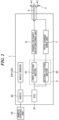
- FIG. 2 is a block diagram that schematically shows a configuration of the propulsion device for the marine vessel shown in FIG. 1 . As shown in FIG.
- the outboard motor 1 includes a driving source 3 including a first electric motor 31 and a second electric motor 32, the propeller 4 including a plurality of blades 41 whose pitches are changeable, and a propeller shaft (a propulsion shaft) 5 to which the propeller 4 is connected.
- the outboard motor 1 includes a propeller shaft rotation drive unit 6 that rotates the propeller shaft 5, a pitch change drive unit 7 that changes the pitch (a pitch angle) of each blade 41, and an angle sensor 231 which functions as an information obtaining unit 23 that obtains information about the pitch angle of each blade 41.
- the outboard motor 1 includes an ECU 21 that transmits drive signals to the first electric motor 31 and the second electric motor 32, respectively, and an AHECU (Actuator Head ECU) 22 which functions as a controller that requests the ECU 21 to switch a driving force in response to an input from the remote control unit 15.
- ECU 21 that transmits drive signals to the first electric motor 31 and the second electric motor 32, respectively
- AHECU 22 Actuator Head ECU 22 which functions as a controller that requests the ECU 21 to switch a driving force in response to an input from the remote control unit 15.
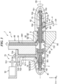
- FIG. 3 is a schematic longitudinal section view of the propulsion device for the marine vessel shown in FIG. 1 , and shows a state in which the pitch angle of each blade 41 of the propeller 4 is minimum.
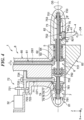
- FIG. 4 is a schematic longitudinal section view of the propulsion device for the marine vessel shown in FIG. 1 , and shows a state in which the pitch angle of each blade 41 of the propeller 4 is maximum.
- the propeller shaft 5 is a member having a cylindrical shape and having a central axis O5 parallel to the X-axis.
- the propeller 4 is connected to the rear end side of the propeller shaft 5 via a second protruding portion 82 of a case (a lower case) 8 which will be described below.
- the propeller 4 rotates around the central axis O5 of the propeller shaft 5 together with the propeller shaft 5.
- the second protruding portion 82 is a member that protrudes in a cylindrical shape toward the rear.
- the propeller 4 is a variable pitch propeller that includes the plurality of blades 41 whose pitches are changeable.
- the plurality of blades 41 are disposed at equal intervals along the circumferential direction of the second protruding portion 82.
- the propeller 4 includes a supporting portion 42 that supports the blades 41 so as to be rotatable around an axis O4 orthogonal to the central axis O5.
- the supporting portion 42 is a columnar (disc-like) portion provided at the base of the blades 41, and is fitted into a through hole 821 that is formed on the outer peripheral portion of the second protruding portion 82.
- Each blade 41 rotates together with the supporting portion 42 around the axis O4 (the respective blades 41 rotate together with the supporting portion 42 around the axis O4), and thus, the pitch of each blade 41 is changed (the pitches of the respective blades 41 are changed).
- an O-ring 43 is disposed between the second protruding portion 82 and the supporting portion 42 within the through hole 821.
- the propeller shaft rotation drive unit 6 rotates the propeller shaft 5 together with the propeller 4 around the central axis O5.
- the propeller shaft rotation drive unit 6 includes a first shaft 61 having a columnar shape and a first converting portion 62.
- the first shaft 61 is disposed along a direction intersecting the central axis O5, that is, along the Z-axis direction.
- the first electric motor 31 is connected to the upper side of the first shaft 61. As a result, the driving force from the first electric motor 31 is transmitted to the first shaft 61, and the first shaft 61 rotates around a central axis O61 of the first shaft 61. It should be noted that in the configuration shown in FIGs.
- the first shaft 61 has an outer diameter that is constant along the central axis O61, but is not limited to have the outer diameter that is constant along the central axis O61, and for example, the first shaft 61 may have a portion whose outer diameter varies along the central axis O61. It should be noted that the first shaft 61 is preferably connected to the first electric motor 31 via a speed reducer (not shown).
- the first converting portion 62 converts a rotational force of the first shaft 61 into a rotational force that rotates the propeller shaft 5.
- the first converting portion 62 includes a first bevel gear 63 provided at the lower end portion of the first shaft 61 and a first bevel gear 64 provided at the front end portion of the propeller shaft 5.
- the first bevel gear 63 rotates together with the first shaft 61 around the central axis O61
- the first bevel gear 64 rotates together with the propeller shaft 5 around the central axis O5.
- the first bevel gear 63 and the first bevel gear 64 mesh with each other.
- the rotational force of the first shaft 61 is transmitted to the propeller shaft 5 via the first bevel gear 63 and the first bevel gear 64 as the rotational force that rotates the propeller shaft 5.
- the propeller shaft rotation drive unit 6 configured as described above, it is possible to transmit the driving force from the first electric motor 31 to the propeller shaft 5 and rapidly and smoothly rotate the propeller shaft 5 around the central axis O5 together with the propeller 4.
- the pitch change drive unit 7 changes the pitch of each blade 41 of the propeller 4.
- the pitch change drive unit 7 includes a second shaft 71 having a columnar shape, a speed reduction portion (a speed reducer) 72, a pitch changing shaft 73 having a columnar shape, a second converting portion 74, and crank portions 75.
- the second shaft 71 is disposed along the Z-axis direction closer to the bow side of the marine vessel 10 than the first shaft 61, that is, the second shaft 71 is disposed parallel to the first shaft 61. It should be noted that in the configuration shown in FIGs.
- the second shaft 71 has an outer diameter that is constant along a central axis O71, but is not limited to have the outer diameter that is constant along the central axis O71, and for example, the second shaft 71 may have a portion whose outer diameter varies along the central axis O71.
- a clearance (a center distance) between the central axis O61 of the first shaft 61 and the central axis O71 of the second shaft 71 is preferably 2 to 6 times of a maximum outer diameter of the first shaft 61, and is more preferably 3 to 5 times of the maximum outer diameter of the first shaft 61.
- the speed reduction portion 72 outputs the driving force of the second electric motor 32 to the second shaft 71 in response to a rotational speed of the second electric motor 32.
- the speed reduction portion 72 includes a first spur gear 721 connected to a rotor (not shown) of the second electric motor 32 and a second spur gear 722 meshing with the first spur gear 721.
- the speed reduction portion 72 includes a worm 724 coaxially connected to the second spur gear 722 via a connecting shaft 723 and a worm wheel 725 that meshes with the worm 724.
- the worm wheel 725 is provided concentrically with the second shaft 71 at the upper portion of the second shaft 71.
- the driving force from the second electric motor 32 is transmitted to the second shaft 71 by the speed reduction portion 72 configured as described above, and the second shaft 71 rotates around the central axis O71.
- the pitch changing shaft 73 is disposed on the inside of the propeller shaft 5 concentrically with the propeller shaft 5. As shown in FIGs. 3 and 4 , the pitch changing shaft 73 is not only able to rotate around the central axis O5 together with the propeller shaft 5, but also able to move along the central axis O5 direction.
- a sliding member 731 which allows sliding due to movement of the pitch changing shaft 73 with respect to the propeller shaft 5, is provided between the outer peripheral portion of the pitch changing shaft 73 and the inner peripheral portion of the propeller shaft 5.
- the second converting portion 74 converts a rotational force of the second shaft 71 into a moving force that moves the pitch changing shaft 73.
- the second converting portion 74 includes a cylindrical rotating body 76, which is disposed closer to the bow side of the marine vessel 10 than the pitch changing shaft 73, and a moving body 79, which is disposed on the inside of the cylindrical rotating body 76.
- the second converting portion 74 includes a second bevel gear 77 provided at the lower end portion of the second shaft 71 and a second bevel gear 78 provided at the rear end portion of the cylindrical rotating body 76.
- the cylindrical rotating body 76 is supported via a bearing 761 so as to be rotatable around the central axis O5.
- the second bevel gear 77 rotates together with the second shaft 71 around the central axis O71
- the second bevel gear 78 rotates together with the cylindrical rotating body 76 around the central axis O5.
- the second bevel gear 77 and the second bevel gear 78 mesh with each other.
- the rotational force of the second shaft 71 is transmitted to the cylindrical rotating body 76 via the second bevel gear 77 and the second bevel gear 78 as a rotational force that rotates the cylindrical rotating body 76.
- the moving body 79 having a columnar shape is disposed on the inside of the cylindrical rotating body 76.
- the moving body 79 is screwed with the cylindrical rotating body 76.
- the moving body 79 is able to move along the central axis O5 direction when the cylindrical rotating body 76 rotates. It should be noted that the moving body 79 advances or retreats in response to a rotation direction of the cylindrical rotating body 76.
- the front end portion of the moving body 79 is supported by a linear bushing 791, and the rear end portion of the moving body 79 is supported by a linear bushing 792.
- the screw engagement between the moving body 79 and the cylindrical rotating body 76 may be, for example, the screw engagement using a trapezoidal screw, the screw engagement using a ball screw, or the like.
- the pitch changing shaft 73 is connected to the rear end portion of the moving body 79.
- the positional relationship in the central axis O5 direction between the moving body 79 and the pitch changing shaft 73 is regulated. Thereby, the pitch changing shaft 73 is able to move along the central axis O5 direction together with the moving body 79.
- the pitch changing shaft 73 is supported via a bearing 732 so as to be rotatable around the central axis O5.
- the pitch changing shaft 73 is also supported via a bearing 733 on the side opposite to the bearing 732, that is, on the rear end side.
- the crank portion 75 converts the movement of the pitch changing shaft 73 into a change of the pitch of each blade 41 (the corresponding blade 41).
- the crank portion 75 includes a protruding portion 751 formed on the outer peripheral portion of the pitch changing shaft 73 to protrude in a columnar shape, a protruding portion 752 formed on the supporting portion 42 of the propeller 4 to protrude in a columnar shape, and a connecting member 753 that connects the protruding portion 751 and the protruding portion 752.
- the protruding portion 751 is formed for each blade 41, that is, the same number of the protruding portions 751 as the blades 41 are formed.
- protruding portions 751 are disposed at equal intervals along the circumferential direction of the pitch changing shaft 73.
- the protruding portion 752 is disposed on the supporting portion 42 at a position eccentric from the axis O4.
- the connecting member 753 has a rod shape, the front end portion of the connecting member 753 fits with the protruding portion 752 with a clearance fit, and the rear end portion of the connecting member 753 fits with the protruding portion 751 with a clearance fit.
- the pitch change drive unit 7 configured as described above, it is possible to transmit the driving force from the second electric motor 32 to the respective blades 41 and collectively change the pitches of the respective blades 41 of the propeller 4 smoothly and quickly. As a result, it is possible to adjust the pitches of the respective blades 41 to a pitch suitable for a speed of the marine vessel 10 and suppress a decrease in the propulsion efficiency of the propeller 4 in respective speed ranges. For example, it is possible to suppress the decrease in the propulsion efficiency of the propeller 4 not only when the marine vessel 10 is navigating at high speed but also when the marine vessel 10 is navigating at medium speed or low speed. As a result, it is possible to improve the power efficiency of the second electric motor 32.
- the pitch change drive unit 7 will be compared with a case where hydraulic pressure is used in the configuration for pitch change (hereinafter, the case is referred to as "a hydraulic pressure configuration").
- the pitch change drive unit 7 is able to improve the responsiveness at the time of pitch change by the gears or the like compared to the hydraulic pressure configuration, and is able to perform the pitch change with the smallest possible force by the crank portions 75 or the like.
- the pitch change drive unit 7 may stop the second electric motor 32 after the pitch change, the pitch change drive unit 7 improves the power efficiency when the pitch is maintained compared to the hydraulic pressure configuration that requires electric power to drive an oil pump in order to maintain the hydraulic pressure.
- the pitch change drive unit 7 is able to perform the pitch change steplessly. As a result, it is possible to adjust the pitch angle to an arbitrary angle.
- the outboard motor 1 includes the information obtaining unit 23 that obtains the information about the pitch angle of each blade 41.
- the information obtaining unit 23 is the angle sensor 231 that is provided in one blade 41 among the plurality of blades 41 and detects the pitch angle itself of the one blade 41.
- the angle sensor 231 is not particularly limited, and for example, may be a sensor using the Hall effect.
- the outboard motor 1 is able to detect the current pitch angle by the angle sensor 231 and further adjust the pitch angle based on the detection result.
- the information about the pitch angle of the blade 41 is not limited to the pitch angle itself, and for example, may be a position of the moving body 79 of the second converting portion 74, or may be a rotation angle or the like of the worm wheel 725 of the speed reduction portion 72.
- the information obtaining unit 23 is the angle sensor 231 in the first preferred embodiment of the present disclosure, the information obtaining unit 23 is not limited to the angle sensor 231, and for example, may be appropriately selected from publicly known sensors in response to the type of the information about the pitch angle of the blade 41.
- the outboard motor 1 includes the case 8 that houses the propeller shaft rotation drive unit 6 and the pitch change drive unit 7.
- the case 8 includes a case main body 80, and a first protruding portion 81 and the second protruding portion 82 that are provided on the lower portion of the case main body 80.
- the first protruding portion 81 is formed integrally with the case main body 80, and is a portion that protrudes in a cylindrical shape toward the bow side.
- a part of the pitch change drive unit 7 (mainly the second converting portion 74 in the first preferred embodiment of the present disclosure) is disposed on the inside of the first protruding portion 81. As a result, it is possible to effectively use the inside of the first protruding portion 81.
- first protruding portion 81 and the second protruding portion 82 are disposed coaxially with the propeller shaft 5, that is, are disposed on the central axis O5.
- first protruding portion 81 and the second protruding portion 82 form a spindle shape as a whole, and thus, it is possible to reduce the propulsion resistance of the outboard motor 1.
- the case 8 includes a fin 83 disposed between the first protruding portion 81 and the second protruding portion 82.
- the fin 83 is a rectifying plate integrally formed on the lower portion of the first protruding portion 81.
- the fin 83 functions as a rudder because it rotates around the steering shaft together with the outboard motor 1 when the marine vessel 10 is steered.
- the driving source 3 includes one electric motor 33.
- the outboard motor 1 includes a power distribution unit 24.
- the power distribution unit 24 is a device that distributes the driving force of the electric motor 33 to the propeller shaft rotation drive unit 6 and the pitch change drive unit 7, that is, a device that switches between the driving force to the propeller shaft rotation drive unit 6 side and the driving force to the pitch change drive unit 7.
- the switching operation of the power distribution unit 24 is controlled by the AHECU 22.
- the marine vessel propulsion device (the propulsion device for the marine vessel) is the outboard motor 1 in each of the above-described preferred embodiments, the teaching is not limited to the outboard motor, and may be, for example, an inboard/outboard motor.
- the first shaft 61 and the second shaft 71 are disposed in parallel in each of the above-described preferred embodiments, they are not limited to this, and may be, for example, in a twisted positional relationship.
Landscapes
- Engineering & Computer Science (AREA)
- Chemical & Material Sciences (AREA)
- Combustion & Propulsion (AREA)
- Mechanical Engineering (AREA)
- Ocean & Marine Engineering (AREA)
- Aviation & Aerospace Engineering (AREA)
- Physics & Mathematics (AREA)
- Fluid Mechanics (AREA)
- Gear Transmission (AREA)
- Connection Of Motors, Electrical Generators, Mechanical Devices, And The Like (AREA)
Abstract
Description
- The present invention relates to a propulsion device for a marine vessel, an outboard motor, and a marine vessel.
- Conventionally, a marine vessel propulsion device including an engine and an electric motor is known as a driving source for driving a propeller. Such a marine vessel propulsion device includes a switching mechanism to switch between the engine and the electric motor, and for example, in the case of being desired to output a propulsion force from the propeller at high output (that is, in the case of a high speed range), the engine is used, and on the other hand, in the case of being desired to output the propulsion force from the propeller at low output (that is, in the case of a low speed range), the electric motor is used (for example, see
JP 2021-146755 A - As is well known, the realization of carbon-free of mobile bodies is being promoted as a means of achieving the SDGs (Sustainable Development Goals) advocated in recent years, and the power source of an automobile, which is an example of the mobile body, is being replaced from a hybrid form of an engine and an electric motor to an electric motor alone. Furthermore, in marine vessel propulsion devices, similar to automobiles, replacement with only electric motors as the power source is under consideration.
- Due to the output characteristics of the electric motor, the higher the rotation speed, the worse the power efficiency (the electricity efficiency). Therefore, in the automobile, a transmission or the like is used to suppress the rotation of the electric motor even during high-speed operation, thereby suppressing the deterioration of the power efficiency.
- On the other hand, although a marine vessel propulsion device, especially an outboard motor, usually does not include a transmission and a pitch (a blade angle) of blades of a propeller is unchanged, in the outboard motor, since the pitch of the blades of the propeller is usually designed so that propulsion efficiency of the propeller becomes optimal when the maximum output of the power source is generated, there is a tendency that the propulsion efficiency of the propeller is lowered in a medium and low speed range where the power source does not generate the maximum output, and the power efficiency of the electric motor is deteriorated. Therefore, there is room for improvement in terms of the power efficiency.
- It is an object of the present invention to provide a propulsion device for marine vessel, an outboard motor and a marine vessel that are each able to improve the power efficiency of an electric motor.
- According to the present invention said object is solved by a propulsion device for marine vessel having the features of
independent claim 1. Moreover, said object is also solved by the subject matter of claims 18 and/or 19. Preferred embodiments are laid down in the dependent claims. - According to a preferred embodiment of the present disclosure, a propulsion device for a marine vessel that propels the marine vessel, the propulsion device includes a driving source including at least one electric motor, a propeller that includes a plurality of blades whose pitches are changeable and rotates around a central axis of a propeller shaft together with the propeller shaft, a propeller shaft rotation drive unit that transmits a driving force from the driving source to the propeller shaft and rotates the propeller shaft around the central axis, and a pitch change drive unit that transmits the driving force from the driving source to the respective blades and changes pitches of the respective blades. The propeller shaft rotation drive unit includes a first shaft. The pitch change drive unit includes a second shaft disposed closer to a bow side of the marine vessel than the first shaft.
- According to another preferred embodiment of the present disclosure, an outboard motor that propels a marine vessel includes a driving source including at least one electric motor, a propeller that includes a plurality of blades whose pitches are changeable and rotates around a central axis of a propeller shaft together with the propeller shaft, a propeller shaft rotation drive unit that transmits a driving force from the driving source to the propeller shaft and rotates the propeller shaft around the central axis, and a pitch change drive unit that transmits the driving force from the driving source to the respective blades and changes pitches of the respective blades.
- According to the preferred embodiments of the present disclosure, since it is possible to change the pitch of each blade of the propeller, it is possible to prevent the propulsion efficiency of the propeller from being lowered even in the medium and low speed range where the power source does not generate the maximum output. As a result, it is possible to improve the power efficiency of the electric motor.
- The above and other elements, features, steps, characteristics and advantages of the present invention will become more apparent from the following detailed description of the preferred embodiments with reference to the attached drawings.
-
-
FIG. 1 is a side view of a marine vessel equipped with a propulsion device for a marine vessel (an outboard motor) according to a first preferred embodiment of the present disclosure. -
FIG. 2 is a block diagram that schematically shows a configuration of the propulsion device for the marine vessel shown inFIG. 1 . -
FIG. 3 is a schematic longitudinal section view of the propulsion device for the marine vessel shown inFIG. 1 , and shows a state in which a pitch angle of each blade of a propeller is minimum. -
FIG. 4 is a schematic longitudinal section view of the propulsion device for the marine vessel shown inFIG. 1 , and shows a state in which the pitch angle of each blade of the propeller is maximum. -
FIG. 5 is a view viewed from a direction of an arrow A inFIG. 3 . -
FIGs. 6A and 6B are schematic horizontal section views of a crank portion included in the propulsion device for the marine vessel shown inFIG. 1 ,FIG. 6A is a cross-sectional view taken along a line B-B inFIG. 3 , andFIG. 6B is a cross-sectional view taken along a line B'-B' inFIG. 4 . -
FIG. 7 is a block diagram that schematically shows a configuration of a propulsion device for a marine vessel (an outboard motor) according to a second preferred embodiment of the present disclosure. - Hereinafter, preferred embodiments of the present disclosure will be described with reference to the drawings.
- Arbitrary two or more configurations (features) of the following preferred embodiments are able to be combined. Furthermore, in
FIGs. 1 ,3 ,4 ,5 ,6A, and 6B , an X-axis, a Y-axis, and a Z-axis that are orthogonal to each other are set. The X-axis is an axis parallel to a longitudinal direction of a marine vessel. The Y-axis is an axis parallel to a width direction of the marine vessel. The Z-axis is an axis parallel to a height direction of the marine vessel. In addition, a direction in which an arrow of each of the X-axis, the Y-axis, and the Z-axis points is defined as "positive", and an opposite direction of "positive" is defined as "negative". In the marine vessel, the positive side of the X-axis is the bow side, the negative side of the X-axis is the stern side, the positive side of the Y-axis is the starboard side, the negative side of the Y-axis is the port side, the positive side of the Z-axis is the upper side, and the negative side of the Z-axis is the lower side. - Hereinafter, a first preferred embodiment of the present disclosure will be described with reference to
FIGs. 1 to 6A and6B .FIG. 1 is a side view of amarine vessel 10 equipped with a propulsion device for a marine vessel (an outboard motor) according to the first preferred embodiment of the present disclosure. Themarine vessel 10 shown inFIG. 1 is a planing boat and includes ahull 11, and anoutboard motor 1 that functions as a marine vessel propulsion device (the propulsion device for the marine vessel) and is mounted on thehull 11. It should be noted that the number ofoutboard motors 1 to be mounted on thehull 11 may be one or may be plural. In the case that a plurality ofoutboard motors 1 are mounted on thehull 11, therespective outboard motors 1 are mounted side by side on the stern of thehull 11. In addition, aremote control unit 15 described below and asteering wheel 14 are provided near a maneuvering seat of thehull 11. - The
outboard motor 1 rotates apropeller 4 to obtain a propulsion force for propelling themarine vessel 10. Theoutboard motor 1 is attached to the stern of thehull 11 via anattachment unit 19, and rotates about a substantially vertical steering shaft (not shown) in theattachment unit 19 in response to an operation of thesteering wheel 14. As a result, themarine vessel 10 is steered.FIG. 2 is a block diagram that schematically shows a configuration of the propulsion device for the marine vessel shown inFIG. 1 . As shown inFIG. 2 , theoutboard motor 1 includes adriving source 3 including a firstelectric motor 31 and a secondelectric motor 32, thepropeller 4 including a plurality ofblades 41 whose pitches are changeable, and a propeller shaft (a propulsion shaft) 5 to which thepropeller 4 is connected. In addition, theoutboard motor 1 includes a propeller shaftrotation drive unit 6 that rotates thepropeller shaft 5, a pitchchange drive unit 7 that changes the pitch (a pitch angle) of eachblade 41, and anangle sensor 231 which functions as aninformation obtaining unit 23 that obtains information about the pitch angle of eachblade 41. Among the two electric motors that constitutes thedriving source 3, the first electric motor (one electric motor) 31 is connected to the propeller shaftrotation drive unit 6, and the second electric motor (the other electric motor) 32 is connected to the pitchchange drive unit 7. In addition, theoutboard motor 1 includes anECU 21 that transmits drive signals to the firstelectric motor 31 and the secondelectric motor 32, respectively, and an AHECU (Actuator Head ECU) 22 which functions as a controller that requests theECU 21 to switch a driving force in response to an input from theremote control unit 15. -
FIG. 3 is a schematic longitudinal section view of the propulsion device for the marine vessel shown inFIG. 1 , and shows a state in which the pitch angle of eachblade 41 of thepropeller 4 is minimum.FIG. 4 is a schematic longitudinal section view of the propulsion device for the marine vessel shown inFIG. 1 , and shows a state in which the pitch angle of eachblade 41 of thepropeller 4 is maximum. As shown inFIGs. 3 and4 , thepropeller shaft 5 is a member having a cylindrical shape and having a central axis O5 parallel to the X-axis. Thepropeller 4 is connected to the rear end side of thepropeller shaft 5 via a second protrudingportion 82 of a case (a lower case) 8 which will be described below. As a result, thepropeller 4 rotates around the central axis O5 of thepropeller shaft 5 together with thepropeller shaft 5. In addition, the second protrudingportion 82 is a member that protrudes in a cylindrical shape toward the rear. Thepropeller 4 is a variable pitch propeller that includes the plurality ofblades 41 whose pitches are changeable. The plurality ofblades 41 are disposed at equal intervals along the circumferential direction of the second protrudingportion 82. In addition, thepropeller 4 includes a supportingportion 42 that supports theblades 41 so as to be rotatable around an axis O4 orthogonal to the central axis O5. The supportingportion 42 is a columnar (disc-like) portion provided at the base of theblades 41, and is fitted into athrough hole 821 that is formed on the outer peripheral portion of the second protrudingportion 82. Eachblade 41 rotates together with the supportingportion 42 around the axis O4 (therespective blades 41 rotate together with the supportingportion 42 around the axis O4), and thus, the pitch of eachblade 41 is changed (the pitches of therespective blades 41 are changed). In addition, an O-ring 43 is disposed between the second protrudingportion 82 and the supportingportion 42 within the throughhole 821. - The propeller shaft
rotation drive unit 6 rotates thepropeller shaft 5 together with thepropeller 4 around the central axis O5. As shown inFIGs. 3 and4 , the propeller shaftrotation drive unit 6 includes afirst shaft 61 having a columnar shape and a first convertingportion 62. Thefirst shaft 61 is disposed along a direction intersecting the central axis O5, that is, along the Z-axis direction. The firstelectric motor 31 is connected to the upper side of thefirst shaft 61. As a result, the driving force from the firstelectric motor 31 is transmitted to thefirst shaft 61, and thefirst shaft 61 rotates around a central axis O61 of thefirst shaft 61. It should be noted that in the configuration shown inFIGs. 3 and4 , thefirst shaft 61 has an outer diameter that is constant along the central axis O61, but is not limited to have the outer diameter that is constant along the central axis O61, and for example, thefirst shaft 61 may have a portion whose outer diameter varies along the central axis O61. It should be noted that thefirst shaft 61 is preferably connected to the firstelectric motor 31 via a speed reducer (not shown). - The first converting
portion 62 converts a rotational force of thefirst shaft 61 into a rotational force that rotates thepropeller shaft 5. The first convertingportion 62 includes afirst bevel gear 63 provided at the lower end portion of thefirst shaft 61 and afirst bevel gear 64 provided at the front end portion of thepropeller shaft 5. Thefirst bevel gear 63 rotates together with thefirst shaft 61 around the central axis O61, and thefirst bevel gear 64 rotates together with thepropeller shaft 5 around the central axis O5. In addition, thefirst bevel gear 63 and thefirst bevel gear 64 mesh with each other. Thereby, the rotational force of thefirst shaft 61 is transmitted to thepropeller shaft 5 via thefirst bevel gear 63 and thefirst bevel gear 64 as the rotational force that rotates thepropeller shaft 5. By the propeller shaftrotation drive unit 6 configured as described above, it is possible to transmit the driving force from the firstelectric motor 31 to thepropeller shaft 5 and rapidly and smoothly rotate thepropeller shaft 5 around the central axis O5 together with thepropeller 4. - The pitch
change drive unit 7 changes the pitch of eachblade 41 of thepropeller 4. As shown inFIGs. 3 and4 , the pitchchange drive unit 7 includes asecond shaft 71 having a columnar shape, a speed reduction portion (a speed reducer) 72, apitch changing shaft 73 having a columnar shape, a second convertingportion 74, and crankportions 75. Thesecond shaft 71 is disposed along the Z-axis direction closer to the bow side of themarine vessel 10 than thefirst shaft 61, that is, thesecond shaft 71 is disposed parallel to thefirst shaft 61. It should be noted that in the configuration shown inFIGs. 3 and4 , thesecond shaft 71 has an outer diameter that is constant along a central axis O71, but is not limited to have the outer diameter that is constant along the central axis O71, and for example, thesecond shaft 71 may have a portion whose outer diameter varies along the central axis O71. A clearance (a center distance) between the central axis O61 of thefirst shaft 61 and the central axis O71 of thesecond shaft 71 is preferably 2 to 6 times of a maximum outer diameter of thefirst shaft 61, and is more preferably 3 to 5 times of the maximum outer diameter of thefirst shaft 61. As a result, for example, it is possible to ensure the degree of freedom in designing the layout of the internal structure of theoutboard motor 1 while suppressing the overall length of theoutboard motor 1 along the X-axis direction. - The
speed reduction portion 72 outputs the driving force of the secondelectric motor 32 to thesecond shaft 71 in response to a rotational speed of the secondelectric motor 32. As shown inFIGs. 3 and4 , thespeed reduction portion 72 includes afirst spur gear 721 connected to a rotor (not shown) of the secondelectric motor 32 and asecond spur gear 722 meshing with thefirst spur gear 721. In addition, as shown inFIG. 5 , thespeed reduction portion 72 includes aworm 724 coaxially connected to thesecond spur gear 722 via a connectingshaft 723 and aworm wheel 725 that meshes with theworm 724. Theworm wheel 725 is provided concentrically with thesecond shaft 71 at the upper portion of thesecond shaft 71. The driving force from the secondelectric motor 32 is transmitted to thesecond shaft 71 by thespeed reduction portion 72 configured as described above, and thesecond shaft 71 rotates around the central axis O71. - The
pitch changing shaft 73 is disposed on the inside of thepropeller shaft 5 concentrically with thepropeller shaft 5. As shown inFIGs. 3 and4 , thepitch changing shaft 73 is not only able to rotate around the central axis O5 together with thepropeller shaft 5, but also able to move along the central axis O5 direction. A slidingmember 731, which allows sliding due to movement of thepitch changing shaft 73 with respect to thepropeller shaft 5, is provided between the outer peripheral portion of thepitch changing shaft 73 and the inner peripheral portion of thepropeller shaft 5. - The second converting
portion 74 converts a rotational force of thesecond shaft 71 into a moving force that moves thepitch changing shaft 73. The second convertingportion 74 includes a cylindrical rotating body 76, which is disposed closer to the bow side of themarine vessel 10 than thepitch changing shaft 73, and a moving body 79, which is disposed on the inside of the cylindrical rotating body 76. In addition, the second convertingportion 74 includes asecond bevel gear 77 provided at the lower end portion of thesecond shaft 71 and asecond bevel gear 78 provided at the rear end portion of the cylindrical rotating body 76. The cylindrical rotating body 76 is supported via abearing 761 so as to be rotatable around the central axis O5. Thesecond bevel gear 77 rotates together with thesecond shaft 71 around the central axis O71, and thesecond bevel gear 78 rotates together with the cylindrical rotating body 76 around the central axis O5. In addition, thesecond bevel gear 77 and thesecond bevel gear 78 mesh with each other. Thereby, the rotational force of thesecond shaft 71 is transmitted to the cylindrical rotating body 76 via thesecond bevel gear 77 and thesecond bevel gear 78 as a rotational force that rotates the cylindrical rotating body 76. The moving body 79 having a columnar shape is disposed on the inside of the cylindrical rotating body 76. The moving body 79 is screwed with the cylindrical rotating body 76. Thereby, the moving body 79 is able to move along the central axis O5 direction when the cylindrical rotating body 76 rotates. It should be noted that the moving body 79 advances or retreats in response to a rotation direction of the cylindrical rotating body 76. In addition, the front end portion of the moving body 79 is supported by alinear bushing 791, and the rear end portion of the moving body 79 is supported by alinear bushing 792. As a result, the moving body 79 becomes able to advance or retreat smoothly. The screw engagement between the moving body 79 and the cylindrical rotating body 76 may be, for example, the screw engagement using a trapezoidal screw, the screw engagement using a ball screw, or the like. - The
pitch changing shaft 73 is connected to the rear end portion of the moving body 79. The positional relationship in the central axis O5 direction between the moving body 79 and thepitch changing shaft 73 is regulated. Thereby, thepitch changing shaft 73 is able to move along the central axis O5 direction together with the moving body 79. At a connecting portion between the moving body 79 and thepitch changing shaft 73, thepitch changing shaft 73 is supported via abearing 732 so as to be rotatable around the central axis O5. In addition, thepitch changing shaft 73 is also supported via abearing 733 on the side opposite to thebearing 732, that is, on the rear end side. - The
crank portion 75 converts the movement of thepitch changing shaft 73 into a change of the pitch of each blade 41 (the corresponding blade 41). As shown inFIGs. 3 and4 , thecrank portion 75 includes a protrudingportion 751 formed on the outer peripheral portion of thepitch changing shaft 73 to protrude in a columnar shape, a protrudingportion 752 formed on the supportingportion 42 of thepropeller 4 to protrude in a columnar shape, and a connectingmember 753 that connects the protrudingportion 751 and the protrudingportion 752. In the pitchchange drive unit 7, the protrudingportion 751 is formed for eachblade 41, that is, the same number of the protrudingportions 751 as theblades 41 are formed. These protrudingportions 751 are disposed at equal intervals along the circumferential direction of thepitch changing shaft 73. In thecrank portion 75, the protrudingportion 752 is disposed on the supportingportion 42 at a position eccentric from the axis O4. The connectingmember 753 has a rod shape, the front end portion of the connectingmember 753 fits with the protrudingportion 752 with a clearance fit, and the rear end portion of the connectingmember 753 fits with the protrudingportion 751 with a clearance fit. By thecrank portion 75 configured as described above, theblade 41 of thepropeller 4 is brought into a state shown inFIG. 6B (that is, a state in which theblade 41 of thepropeller 4 has been rotated clockwise around the central axis O4) from a state shown inFIG. 6A by thepitch changing shaft 73 moving rearward. The pitch of theblade 41 is changed by this rotation. - By the pitch
change drive unit 7 configured as described above, it is possible to transmit the driving force from the secondelectric motor 32 to therespective blades 41 and collectively change the pitches of therespective blades 41 of thepropeller 4 smoothly and quickly. As a result, it is possible to adjust the pitches of therespective blades 41 to a pitch suitable for a speed of themarine vessel 10 and suppress a decrease in the propulsion efficiency of thepropeller 4 in respective speed ranges. For example, it is possible to suppress the decrease in the propulsion efficiency of thepropeller 4 not only when themarine vessel 10 is navigating at high speed but also when themarine vessel 10 is navigating at medium speed or low speed. As a result, it is possible to improve the power efficiency of the secondelectric motor 32. - Here, for example, the pitch
change drive unit 7 will be compared with a case where hydraulic pressure is used in the configuration for pitch change (hereinafter, the case is referred to as "a hydraulic pressure configuration"). The pitchchange drive unit 7 is able to improve the responsiveness at the time of pitch change by the gears or the like compared to the hydraulic pressure configuration, and is able to perform the pitch change with the smallest possible force by thecrank portions 75 or the like. In addition, since the pitchchange drive unit 7 may stop the secondelectric motor 32 after the pitch change, the pitchchange drive unit 7 improves the power efficiency when the pitch is maintained compared to the hydraulic pressure configuration that requires electric power to drive an oil pump in order to maintain the hydraulic pressure. - The pitch
change drive unit 7 is able to perform the pitch change steplessly. As a result, it is possible to adjust the pitch angle to an arbitrary angle. As described above, theoutboard motor 1 includes theinformation obtaining unit 23 that obtains the information about the pitch angle of eachblade 41. In the first preferred embodiment of the present disclosure, theinformation obtaining unit 23 is theangle sensor 231 that is provided in oneblade 41 among the plurality ofblades 41 and detects the pitch angle itself of the oneblade 41. Theangle sensor 231 is not particularly limited, and for example, may be a sensor using the Hall effect. Theoutboard motor 1 is able to detect the current pitch angle by theangle sensor 231 and further adjust the pitch angle based on the detection result. It should be noted that the information about the pitch angle of theblade 41 is not limited to the pitch angle itself, and for example, may be a position of the moving body 79 of the second convertingportion 74, or may be a rotation angle or the like of theworm wheel 725 of thespeed reduction portion 72. In addition, although theinformation obtaining unit 23 is theangle sensor 231 in the first preferred embodiment of the present disclosure, theinformation obtaining unit 23 is not limited to theangle sensor 231, and for example, may be appropriately selected from publicly known sensors in response to the type of the information about the pitch angle of theblade 41. - As shown in
FIGs. 3 and4 , theoutboard motor 1 includes thecase 8 that houses the propeller shaftrotation drive unit 6 and the pitchchange drive unit 7. Thecase 8 includes a casemain body 80, and a first protrudingportion 81 and the second protrudingportion 82 that are provided on the lower portion of the casemain body 80. The first protrudingportion 81 is formed integrally with the casemain body 80, and is a portion that protrudes in a cylindrical shape toward the bow side. A part of the pitch change drive unit 7 (mainly the second convertingportion 74 in the first preferred embodiment of the present disclosure) is disposed on the inside of the first protrudingportion 81. As a result, it is possible to effectively use the inside of the first protrudingportion 81. The second protrudingportion 82 is formed separately from the casemain body 80, and is a portion that protrudes in a cylindrical shape toward the stern side. A part of the pitch change drive unit 7 (mainly thepitch changing shaft 73 and the crankportions 75 in the first preferred embodiment of the present disclosure) is disposed on the inside of the second protrudingportion 82. As a result, it is possible to effectively use the inside of the second protrudingportion 82. The first protrudingportion 81 has a shape whose outer diameter gradually decreases toward the bow side, and the second protrudingportion 82 has a shape whose outer diameter gradually decreases toward the stern side. In addition, the first protrudingportion 81 and the second protrudingportion 82 are disposed coaxially with thepropeller shaft 5, that is, are disposed on the central axis O5. As a result, the first protrudingportion 81 and the second protrudingportion 82 form a spindle shape as a whole, and thus, it is possible to reduce the propulsion resistance of theoutboard motor 1. Thecase 8 includes afin 83 disposed between the first protrudingportion 81 and the second protrudingportion 82. Thefin 83 is a rectifying plate integrally formed on the lower portion of the first protrudingportion 81. Thefin 83 functions as a rudder because it rotates around the steering shaft together with theoutboard motor 1 when themarine vessel 10 is steered. - Hereinafter, a second preferred embodiment of the present disclosure will be described with reference to
FIG. 7 , the description of the second preferred embodiment will focus on the differences from the first preferred embodiment described above, and the description of the same matters will be omitted. As shown inFIG. 7 , in the second preferred embodiment, the drivingsource 3 includes oneelectric motor 33. In addition, theoutboard motor 1 includes apower distribution unit 24. Thepower distribution unit 24 is a device that distributes the driving force of theelectric motor 33 to the propeller shaftrotation drive unit 6 and the pitchchange drive unit 7, that is, a device that switches between the driving force to the propeller shaftrotation drive unit 6 side and the driving force to the pitchchange drive unit 7. The switching operation of thepower distribution unit 24 is controlled by theAHECU 22. It should be noted that the configuration of thepower distribution unit 24 is not particularly limited, and for example, may be a configuration in which a plurality of gears are provided and these gears are engaged with each other or separated from each other. Since theoutboard motor 1 configured as described above (theoutboard motor 1 of the second preferred embodiment) includes only one electric motor, it is possible to make it lighter than theoutboard motor 1 of the first preferred embodiment. - Although the marine vessel propulsion device (the propulsion device for the marine vessel) is the
outboard motor 1 in each of the above-described preferred embodiments, the teaching is not limited to the outboard motor, and may be, for example, an inboard/outboard motor. Moreover, although thefirst shaft 61 and thesecond shaft 71 are disposed in parallel in each of the above-described preferred embodiments, they are not limited to this, and may be, for example, in a twisted positional relationship.
Claims (19)
- A propulsion device for a marine vessel that is configured to propel the marine vessel (10), the propulsion device comprising:a driving source (3) including at least one electric motor (31, 32);a propeller (4) that includes a plurality of blades (41) whose pitches are changeable and are rotatable around a central axis (O5) of a propeller shaft (5) together with the propeller shaft (5), the propeller shaft (5) extends in a central axis direction thereof;a propeller shaft rotation drive unit (6) that is configured to transmit a driving force from the driving source (3) to the propeller shaft (5) and is configured to rotate the propeller shaft (5) around the central axis (O5); anda pitch change drive unit (7) that is configured to transmit the driving force from the driving source (3) to the respective blades (41) and is configured to change pitches of the respective blades (41).
- The propulsion device for the marine vessel according to claim 1, wherein the propeller shaft rotation drive unit (6) includes a first shaft (61), and
the pitch change drive unit (7) includes a second shaft (71), wherein first shaft (61) is arranged between the propeller (4) and the second shaft (71) with regard to a central axis direction of the propeller shaft (5). - The propulsion device for the marine vessel according to claim 2, wherein the first shaft (61) and the second shaft (71) are disposed along a direction intersecting the central axis (O5), respectively.
- The propulsion device for the marine vessel according to any one of the claims 1 to 3, wherein the propeller shaft rotation drive unit (6) includes a first converting portion (62), which is configured to convert a rotational force of the first shaft (61) into a rotational force that rotates the propeller shaft (5).
- The propulsion device for the marine vessel according to claim 4, wherein the first converting portion (62) includes first bevel gears (63, 64) provided on both the first shaft (61) and the propeller shaft (5) and meshing with each other.
- The propulsion device for the marine vessel according to any one of the claims 1 to 5, wherein the propeller shaft (5) has a cylindrical shape, and the pitch change drive unit (7) includesa pitch changing shaft (73) that is disposed on the inside of the propeller shaft (5) and is movable along the central axis direction of the propeller shaft (5), anda second converting portion (74) that is configured to convert a rotational force of the second shaft (71) into a moving force that moves the pitch changing shaft (73).
- The propulsion device for the marine vessel according to claim 6, wherein the second converting portion (74) includesa cylindrical rotating body (76) that is configured to rotate around the central axis (O5);second bevel gears (77, 78) provided on both the second shaft (71) and the cylindrical rotating body (76) and meshing with each other; anda moving body (79) that is disposed on the inside of the cylindrical rotating body (76), is screwed with the cylindrical rotating body (76), and is movable along the central axis direction of the propeller shaft (5) together with the pitch changing shaft (73) by rotation of the cylindrical rotating body (76).
- The propulsion device for the marine vessel according to claim 6 or 7, wherein the pitch change drive unit (7) includes crank portions (75) that each is configured to convert movement of the pitch changing shaft (73) into a change of the pitch of each of the blades (41).
- The propulsion device for the marine vessel according to any one of the claims 1 to 8, wherein the pitch change drive unit (7) is configured to perform a change of the pitch steplessly.
- The propulsion device for the marine vessel according to any one of the claims 1 to 9, further comprising:
an information obtaining unit (23) that obtains information about a pitch angle of each of the blades (41). - The propulsion device for the marine vessel according to any one of the claims 2 to 10, wherein the first shaft (61) and the second shaft (71) are disposed in parallel.
- The propulsion device for the marine vessel according to any one of the claims 2 to 11, wherein a clearance between the first shaft (61) and the second shaft (71) is 2 to 6 times of a maximum outer diameter of the first shaft (61).
- The propulsion device for the marine vessel according to any one of the claims 1 to 12, further comprising:a case (8) that houses the propeller shaft rotation drive unit (6) and the pitch change drive unit (7), andwherein the case (8) includes a first protruding portion (81) that protrudes in a cylindrical shape in a first direction of the central axis direction of the propeller shaft (5), anda part of the pitch change drive unit (7) is disposed on the inside of the first protruding portion (81).
- The propulsion device for the marine vessel according to claim 13, wherein the first protruding portion (81) has a shape whose outer diameter gradually decreases in the first direction of the central axis direction of the propeller shaft (5).
- The propulsion device for the marine vessel according to claim 13 or 14, wherein the first protruding portion (81) is disposed coaxially with the propeller shaft (5).
- The propulsion device for the marine vessel according to any one of the claims 13 to 15, wherein the case (8) includes a second protruding portion (82) that protrudes in a cylindrical shape in a second direction opposite to the first direction of the central axis direction of the propeller shaft (5),the second protruding portion (82) has a shape whose outer diameter gradually decreases toward the second direction of the central axis direction of the propeller shaft (5), andthe case (8) includes a fin (83) disposed between the first protruding portion (81) and the second protruding portion (82) with regard to the central axis direction of the propeller shaft (5).
- The propulsion device for the marine vessel according to any one of the claims 1 to 16, wherein the driving source (3) includes the two electric motors (31, 32), and among the two electric motors (31, 32), a first electric motor (31) is connected to the propeller shaft rotation drive unit (6) and a second electric motor (32) is connected to the pitch change drive unit (7).
- The propulsion device for the marine vessel according to any one of the claims 1 to 17, wherein the propulsion device for the marine vessel is an outboard motor (1).
- A marine vessel having a hull (11) and a propulsion device for the marine vessel according to any one of the claims 1 to 18, attached to a bow of the hull (11), the second shaft (71) is disposed closer to a bow side of the marine vessel (10) than the first shaft (61), and the first direction of the central axis direction of the propeller shaft (5) is directed to the bow side of the marine vessel (10) and the second direction of the central axis direction of the propeller shaft (5) is directed rearward from the marine vessel (10).
Applications Claiming Priority (1)
| Application Number | Priority Date | Filing Date | Title |
|---|---|---|---|
| JP2022102553A JP2024003425A (en) | 2022-06-27 | 2022-06-27 | Marine propulsion engines and outboard motors |
Publications (2)
| Publication Number | Publication Date |
|---|---|
| EP4299434A1 true EP4299434A1 (en) | 2024-01-03 |
| EP4299434B1 EP4299434B1 (en) | 2025-10-01 |
Family
ID=86851552
Family Applications (1)
| Application Number | Title | Priority Date | Filing Date |
|---|---|---|---|
| EP23179523.8A Active EP4299434B1 (en) | 2022-06-27 | 2023-06-15 | Propulsion device for marine vessel, outboard motor and marine vessel |
Country Status (3)
| Country | Link |
|---|---|
| US (1) | US12576956B2 (en) |
| EP (1) | EP4299434B1 (en) |
| JP (1) | JP2024003425A (en) |
Families Citing this family (3)
| Publication number | Priority date | Publication date | Assignee | Title |
|---|---|---|---|---|
| JP2024050232A (en) * | 2022-09-29 | 2024-04-10 | 本田技研工業株式会社 | Ship propeller propulsion system |
| EP4778826A1 (en) * | 2025-01-21 | 2026-07-22 | Volvo Penta Corporation | A pod drive unit |
| EP4778825A1 (en) * | 2025-01-21 | 2026-07-22 | Volvo Penta Corporation | A pod drive unit |
Citations (5)
| Publication number | Priority date | Publication date | Assignee | Title |
|---|---|---|---|---|
| US4900280A (en) * | 1988-08-16 | 1990-02-13 | Midttun Ole H | Apparatus for detecting the pitch of a marine controllable pitch propeller |
| US4950187A (en) * | 1989-05-22 | 1990-08-21 | Smith Rodney L | Trolling motor foot control apparatus |
| WO2005012078A1 (en) * | 2003-07-25 | 2005-02-10 | Aimbridge Pty Ltd | Marine propulsion system |
| EP2520487A2 (en) * | 2011-05-05 | 2012-11-07 | Solas Science & Engineering Co., Ltd. | Electric outboard drive |
| JP2021146755A (en) | 2020-03-16 | 2021-09-27 | ヤマハ発動機株式会社 | Control system for ship propulsion machine, and method for switching drive source of ship propulsion machine |
Family Cites Families (1)
| Publication number | Priority date | Publication date | Assignee | Title |
|---|---|---|---|---|
| JP7452214B2 (en) * | 2020-04-14 | 2024-03-19 | スズキ株式会社 | ship propulsion machine |
-
2022
- 2022-06-27 JP JP2022102553A patent/JP2024003425A/en active Pending
-
2023
- 2023-06-15 EP EP23179523.8A patent/EP4299434B1/en active Active
- 2023-06-26 US US18/213,936 patent/US12576956B2/en active Active
Patent Citations (5)
| Publication number | Priority date | Publication date | Assignee | Title |
|---|---|---|---|---|
| US4900280A (en) * | 1988-08-16 | 1990-02-13 | Midttun Ole H | Apparatus for detecting the pitch of a marine controllable pitch propeller |
| US4950187A (en) * | 1989-05-22 | 1990-08-21 | Smith Rodney L | Trolling motor foot control apparatus |
| WO2005012078A1 (en) * | 2003-07-25 | 2005-02-10 | Aimbridge Pty Ltd | Marine propulsion system |
| EP2520487A2 (en) * | 2011-05-05 | 2012-11-07 | Solas Science & Engineering Co., Ltd. | Electric outboard drive |
| JP2021146755A (en) | 2020-03-16 | 2021-09-27 | ヤマハ発動機株式会社 | Control system for ship propulsion machine, and method for switching drive source of ship propulsion machine |
Also Published As
| Publication number | Publication date |
|---|---|
| EP4299434B1 (en) | 2025-10-01 |
| US12576956B2 (en) | 2026-03-17 |
| JP2024003425A (en) | 2024-01-15 |
| US20230415871A1 (en) | 2023-12-28 |
Similar Documents
| Publication | Publication Date | Title |
|---|---|---|
| EP4299434B1 (en) | Propulsion device for marine vessel, outboard motor and marine vessel | |
| US7131385B1 (en) | Method for braking a vessel with two marine propulsion devices | |
| US20110263165A1 (en) | Electric Marine Surface Drive | |
| RU2198818C2 (en) | Power plant | |
| US7325505B2 (en) | Outboard motor steering control system | |
| KR20030063214A (en) | Ship and operating method therefor | |
| US7485018B2 (en) | Marine drive system | |
| JP2012081899A (en) | Marine vessel propulsion apparatus | |
| CN202295269U (en) | 360-degree all rotation outboard and inboard double-motor contra-rotating propeller propelling device | |
| CN102390508A (en) | 360-degree full revolving inboard and outboard (dual-machine) contrarotating propeller propulsion device | |
| KR101091759B1 (en) | Linear elevating stern propulsion system | |
| US8393924B1 (en) | Watercraft control system | |
| KR101261867B1 (en) | Pod type propulsion device and ship with the same | |
| US9296453B2 (en) | Control apparatus for boat | |
| CN218506103U (en) | A kind of ship drive system and ship | |
| CN218506107U (en) | Outboards and Ships | |
| JP2012183929A (en) | Control apparatus of multiple ship propellers | |
| CN113636057B (en) | Separating rudder capable of realizing forward and reverse rudder conversion | |
| EP3353049B1 (en) | A method and an arrangement for maneuvering a marine vessel | |
| US9849955B1 (en) | Marine surface propulsion device | |
| WO2024100386A1 (en) | Motor | |
| CN117048792A (en) | A pod ship model testing device | |
| JP2018027765A (en) | Ship propulsion system | |
| JP3904479B2 (en) | Outboard motor steering system | |
| CN218506108U (en) | Outboard motor and ship |
Legal Events
| Date | Code | Title | Description |
|---|---|---|---|
| PUAI | Public reference made under article 153(3) epc to a published international application that has entered the european phase |
Free format text: ORIGINAL CODE: 0009012 |
|
| STAA | Information on the status of an ep patent application or granted ep patent |
Free format text: STATUS: THE APPLICATION HAS BEEN PUBLISHED |
|
| AK | Designated contracting states |
Kind code of ref document: A1 Designated state(s): AL AT BE BG CH CY CZ DE DK EE ES FI FR GB GR HR HU IE IS IT LI LT LU LV MC ME MK MT NL NO PL PT RO RS SE SI SK SM TR |
|
| STAA | Information on the status of an ep patent application or granted ep patent |
Free format text: STATUS: REQUEST FOR EXAMINATION WAS MADE |
|
| P01 | Opt-out of the competence of the unified patent court (upc) registered |
Free format text: CASE NUMBER: APP_37585/2024 Effective date: 20240624 |
|
| 17P | Request for examination filed |
Effective date: 20240703 |
|
| RBV | Designated contracting states (corrected) |
Designated state(s): AL AT BE BG CH CY CZ DE DK EE ES FI FR GB GR HR HU IE IS IT LI LT LU LV MC ME MK MT NL NO PL PT RO RS SE SI SK SM TR |
|
| GRAP | Despatch of communication of intention to grant a patent |
Free format text: ORIGINAL CODE: EPIDOSNIGR1 |
|
| STAA | Information on the status of an ep patent application or granted ep patent |
Free format text: STATUS: GRANT OF PATENT IS INTENDED |
|
| INTG | Intention to grant announced |
Effective date: 20250627 |
|
| GRAS | Grant fee paid |
Free format text: ORIGINAL CODE: EPIDOSNIGR3 |
|
| GRAA | (expected) grant |
Free format text: ORIGINAL CODE: 0009210 |
|
| STAA | Information on the status of an ep patent application or granted ep patent |
Free format text: STATUS: THE PATENT HAS BEEN GRANTED |
|
| AK | Designated contracting states |
Kind code of ref document: B1 Designated state(s): AL AT BE BG CH CY CZ DE DK EE ES FI FR GB GR HR HU IE IS IT LI LT LU LV MC ME MK MT NL NO PL PT RO RS SE SI SK SM TR |
|
| REG | Reference to a national code |
Ref country code: GB Ref legal event code: FG4D Ref country code: CH Ref legal event code: F10 Free format text: ST27 STATUS EVENT CODE: U-0-0-F10-F00 (AS PROVIDED BY THE NATIONAL OFFICE) Effective date: 20251001 |
|
| REG | Reference to a national code |
Ref country code: IE Ref legal event code: FG4D |
|
| REG | Reference to a national code |
Ref country code: DE Ref legal event code: R096 Ref document number: 602023007063 Country of ref document: DE |
|
| REG | Reference to a national code |
Ref country code: NL Ref legal event code: MP Effective date: 20251001 |
|
| REG | Reference to a national code |
Ref country code: AT Ref legal event code: MK05 Ref document number: 1842296 Country of ref document: AT Kind code of ref document: T Effective date: 20251001 |
|
| PG25 | Lapsed in a contracting state [announced via postgrant information from national office to epo] |
Ref country code: NL Free format text: LAPSE BECAUSE OF FAILURE TO SUBMIT A TRANSLATION OF THE DESCRIPTION OR TO PAY THE FEE WITHIN THE PRESCRIBED TIME-LIMIT Effective date: 20251001 |
|
| PG25 | Lapsed in a contracting state [announced via postgrant information from national office to epo] |
Ref country code: ES Free format text: LAPSE BECAUSE OF FAILURE TO SUBMIT A TRANSLATION OF THE DESCRIPTION OR TO PAY THE FEE WITHIN THE PRESCRIBED TIME-LIMIT Effective date: 20251001 |
|
| REG | Reference to a national code |
Ref country code: LT Ref legal event code: MG9D |
|
| PG25 | Lapsed in a contracting state [announced via postgrant information from national office to epo] |
Ref country code: NO Free format text: LAPSE BECAUSE OF FAILURE TO SUBMIT A TRANSLATION OF THE DESCRIPTION OR TO PAY THE FEE WITHIN THE PRESCRIBED TIME-LIMIT Effective date: 20260101 |
|
| PG25 | Lapsed in a contracting state [announced via postgrant information from national office to epo] |
Ref country code: FI Free format text: LAPSE BECAUSE OF FAILURE TO SUBMIT A TRANSLATION OF THE DESCRIPTION OR TO PAY THE FEE WITHIN THE PRESCRIBED TIME-LIMIT Effective date: 20251001 Ref country code: HR Free format text: LAPSE BECAUSE OF FAILURE TO SUBMIT A TRANSLATION OF THE DESCRIPTION OR TO PAY THE FEE WITHIN THE PRESCRIBED TIME-LIMIT Effective date: 20251001 Ref country code: AT Free format text: LAPSE BECAUSE OF FAILURE TO SUBMIT A TRANSLATION OF THE DESCRIPTION OR TO PAY THE FEE WITHIN THE PRESCRIBED TIME-LIMIT Effective date: 20251001 |
|
| PG25 | Lapsed in a contracting state [announced via postgrant information from national office to epo] |
Ref country code: RS Free format text: LAPSE BECAUSE OF FAILURE TO SUBMIT A TRANSLATION OF THE DESCRIPTION OR TO PAY THE FEE WITHIN THE PRESCRIBED TIME-LIMIT Effective date: 20260101 |
|
| PG25 | Lapsed in a contracting state [announced via postgrant information from national office to epo] |
Ref country code: IS Free format text: LAPSE BECAUSE OF FAILURE TO SUBMIT A TRANSLATION OF THE DESCRIPTION OR TO PAY THE FEE WITHIN THE PRESCRIBED TIME-LIMIT Effective date: 20260201 |
|
| PG25 | Lapsed in a contracting state [announced via postgrant information from national office to epo] |
Ref country code: PT Free format text: LAPSE BECAUSE OF FAILURE TO SUBMIT A TRANSLATION OF THE DESCRIPTION OR TO PAY THE FEE WITHIN THE PRESCRIBED TIME-LIMIT Effective date: 20260202 Ref country code: CZ Free format text: LAPSE BECAUSE OF FAILURE TO SUBMIT A TRANSLATION OF THE DESCRIPTION OR TO PAY THE FEE WITHIN THE PRESCRIBED TIME-LIMIT Effective date: 20251001 |
|
| PG25 | Lapsed in a contracting state [announced via postgrant information from national office to epo] |
Ref country code: PL Free format text: LAPSE BECAUSE OF FAILURE TO SUBMIT A TRANSLATION OF THE DESCRIPTION OR TO PAY THE FEE WITHIN THE PRESCRIBED TIME-LIMIT Effective date: 20251001 |
|
| PG25 | Lapsed in a contracting state [announced via postgrant information from national office to epo] |
Ref country code: LV Free format text: LAPSE BECAUSE OF FAILURE TO SUBMIT A TRANSLATION OF THE DESCRIPTION OR TO PAY THE FEE WITHIN THE PRESCRIBED TIME-LIMIT Effective date: 20251001 |
|
| PG25 | Lapsed in a contracting state [announced via postgrant information from national office to epo] |
Ref country code: BG Free format text: LAPSE BECAUSE OF FAILURE TO SUBMIT A TRANSLATION OF THE DESCRIPTION OR TO PAY THE FEE WITHIN THE PRESCRIBED TIME-LIMIT Effective date: 20251001 |
|
| PG25 | Lapsed in a contracting state [announced via postgrant information from national office to epo] |
Ref country code: LT Free format text: LAPSE BECAUSE OF FAILURE TO SUBMIT A TRANSLATION OF THE DESCRIPTION OR TO PAY THE FEE WITHIN THE PRESCRIBED TIME-LIMIT Effective date: 20251001 |
|
| REG | Reference to a national code |
Ref country code: DE Ref legal event code: R097 Ref document number: 602023007063 Country of ref document: DE |
|
| PG25 | Lapsed in a contracting state [announced via postgrant information from national office to epo] |
Ref country code: SM Free format text: LAPSE BECAUSE OF FAILURE TO SUBMIT A TRANSLATION OF THE DESCRIPTION OR TO PAY THE FEE WITHIN THE PRESCRIBED TIME-LIMIT Effective date: 20251001 |
|
| PG25 | Lapsed in a contracting state [announced via postgrant information from national office to epo] |
Ref country code: DK Free format text: LAPSE BECAUSE OF FAILURE TO SUBMIT A TRANSLATION OF THE DESCRIPTION OR TO PAY THE FEE WITHIN THE PRESCRIBED TIME-LIMIT Effective date: 20251001 |
|
| PG25 | Lapsed in a contracting state [announced via postgrant information from national office to epo] |
Ref country code: EE Free format text: LAPSE BECAUSE OF FAILURE TO SUBMIT A TRANSLATION OF THE DESCRIPTION OR TO PAY THE FEE WITHIN THE PRESCRIBED TIME-LIMIT Effective date: 20251001 |
|
| PGFP | Annual fee paid to national office [announced via postgrant information from national office to epo] |
Ref country code: FR Payment date: 20260626 Year of fee payment: 4 |
|
| PG25 | Lapsed in a contracting state [announced via postgrant information from national office to epo] |
Ref country code: SK Free format text: LAPSE BECAUSE OF FAILURE TO SUBMIT A TRANSLATION OF THE DESCRIPTION OR TO PAY THE FEE WITHIN THE PRESCRIBED TIME-LIMIT Effective date: 20251001 |
|
| PG25 | Lapsed in a contracting state [announced via postgrant information from national office to epo] |
Ref country code: SE Free format text: LAPSE BECAUSE OF FAILURE TO SUBMIT A TRANSLATION OF THE DESCRIPTION OR TO PAY THE FEE WITHIN THE PRESCRIBED TIME-LIMIT Effective date: 20251001 |
|
| PLBE | No opposition filed within time limit |
Free format text: ORIGINAL CODE: 0009261 |
|
| STAA | Information on the status of an ep patent application or granted ep patent |
Free format text: STATUS: NO OPPOSITION FILED WITHIN TIME LIMIT |
|
| REG | Reference to a national code |
Ref country code: CH Ref legal event code: L10 Free format text: ST27 STATUS EVENT CODE: U-0-0-L10-L00 (AS PROVIDED BY THE NATIONAL OFFICE) Effective date: 20260812 |