EP4299393A1 - Method and system of controlling a vehicle on a downslope route - Google Patents
Method and system of controlling a vehicle on a downslope route Download PDFInfo
- Publication number
- EP4299393A1 EP4299393A1 EP23182717.1A EP23182717A EP4299393A1 EP 4299393 A1 EP4299393 A1 EP 4299393A1 EP 23182717 A EP23182717 A EP 23182717A EP 4299393 A1 EP4299393 A1 EP 4299393A1
- Authority
- EP
- European Patent Office
- Prior art keywords
- brake
- vehicle
- foundation
- power
- profile
- Prior art date
- Legal status (The legal status is an assumption and is not a legal conclusion. Google has not performed a legal analysis and makes no representation as to the accuracy of the status listed.)
- Granted
Links
Images



Classifications
-
- B—PERFORMING OPERATIONS; TRANSPORTING
- B60—VEHICLES IN GENERAL
- B60T—VEHICLE BRAKE CONTROL SYSTEMS OR PARTS THEREOF; BRAKE CONTROL SYSTEMS OR PARTS THEREOF, IN GENERAL; ARRANGEMENT OF BRAKING ELEMENTS ON VEHICLES IN GENERAL; PORTABLE DEVICES FOR PREVENTING UNWANTED MOVEMENT OF VEHICLES; VEHICLE MODIFICATIONS TO FACILITATE COOLING OF BRAKES
- B60T8/00—Arrangements for adjusting wheel-braking force to meet varying vehicular or ground-surface conditions, e.g. limiting or varying distribution of braking force
- B60T8/17—Using electrical or electronic regulation means to control braking
- B60T8/1701—Braking or traction control means specially adapted for particular types of vehicles
- B60T8/1708—Braking or traction control means specially adapted for particular types of vehicles for lorries or tractor-trailer combinations
-
- B—PERFORMING OPERATIONS; TRANSPORTING
- B60—VEHICLES IN GENERAL
- B60T—VEHICLE BRAKE CONTROL SYSTEMS OR PARTS THEREOF; BRAKE CONTROL SYSTEMS OR PARTS THEREOF, IN GENERAL; ARRANGEMENT OF BRAKING ELEMENTS ON VEHICLES IN GENERAL; PORTABLE DEVICES FOR PREVENTING UNWANTED MOVEMENT OF VEHICLES; VEHICLE MODIFICATIONS TO FACILITATE COOLING OF BRAKES
- B60T13/00—Transmitting braking action from initiating means to ultimate brake actuator with power assistance or drive; Brake systems incorporating such transmitting means, e.g. air-pressure brake systems
- B60T13/10—Transmitting braking action from initiating means to ultimate brake actuator with power assistance or drive; Brake systems incorporating such transmitting means, e.g. air-pressure brake systems with fluid assistance, drive, or release
- B60T13/58—Combined or convertible systems
- B60T13/585—Combined or convertible systems comprising friction brakes and retarders
- B60T13/586—Combined or convertible systems comprising friction brakes and retarders the retarders being of the electric type
-
- B—PERFORMING OPERATIONS; TRANSPORTING
- B60—VEHICLES IN GENERAL
- B60T—VEHICLE BRAKE CONTROL SYSTEMS OR PARTS THEREOF; BRAKE CONTROL SYSTEMS OR PARTS THEREOF, IN GENERAL; ARRANGEMENT OF BRAKING ELEMENTS ON VEHICLES IN GENERAL; PORTABLE DEVICES FOR PREVENTING UNWANTED MOVEMENT OF VEHICLES; VEHICLE MODIFICATIONS TO FACILITATE COOLING OF BRAKES
- B60T2201/00—Particular use of vehicle brake systems; Special systems using also the brakes; Special software modules within the brake system controller
- B60T2201/04—Hill descent control
Definitions
- an engine retarder system that e.g. uses the internal combustion engine as a compression brake, by actively controlling intake and exhaust valves and increase back pressure to the engine.
- Compression braking is a concept known from e.g. EP1389270 .
- exhaust valves may be selectively opened to convert, at least temporarily, a power producing internal combustion engine into a power absorbing air compressor.
- An engine retarder system controls a lift of the exhaust valves, e.g. by a hydraulic actuator. At the beginning of the compression stroke the exhaust valves are opened and high pressurized air from the exhaust manifold flows back into the cylinder which increases the initial pressure during compression by back gas recirculation.
- boost pressure needs to be dropped below a certain level before the brake mode can be selected to prevent too high forces in valve train in brake mode; in addition, hydraulic lag of valve operation system generates a delay, since all specific oil channels have to be filled when brake mode is activated; also settings for the variable turbine geometry (VTG) - if present are adapted.
- VVTG variable turbine geometry
- a downshift of gears is usually necessary in order to attain a suitable brake power, and then the gradual increase of brake power in conjunction with increasing back pressure of the combustion engine constitutes the engine retarder mode until full brake power is achieved.
- An alternative system is a so called 'intarder' which is a hydraulic brake incorporated in the gearbox of the driveline, also called a driveline retarder, and that has a quick response compared to the engine retarder.
- the intarder brake adds to fuel costs since it increases friction by hydraulic drag in the drive line, so creating losses when it is not engaged.
- the intarder adds to the costs and weight of the manufacturing the vehicle, which are preferably to be reduced.
- the invention aims to provide a solution obviate the problems of the prior art, to increase user comfort, while at the same time optimizing energy consumption.
- a brake controller programmed to:
- the system and corresponding method avoids the use of an additional endurance brake device such as an intarder and the truck becomes more energy efficient due to absence of such brake devices.
- FIG. 1A shows a generic setup for a vehicle 1 including a combustion engine provided with an engine retarder 100, which is a specific function of the engine including structure that will not be described in the detailed description since it is known conventionally and has certain features, that provides a response as described in the introduction and will be further elaborated below.
- the vehicle 1 has a velocity V and a driveline 15, that includes a clutch and a transmission 300.
- the transmission 300 may be equipped with an driveline retarder system, which is a hydraulic brake with a brake response that will be described below and is known to the skilled person.
- the vehicle 1 is equipped with foundation brakes 400, that brake the wheels and are typically provided through brake pads and disc brakes.
- the classical idea behind of endurance braking is not to use the foundation brakes and save money on service cost (so to extend the lifetime of the brake pads and disc brakes).
- the foundation brakes are activated in the initial phase of braking, and a well-balanced trade-off is made between a good initial braking response versus extra wear for the service brakes.
- FIG. 1B in more detail shows a brake controller according to an aspect of the invention, that controls the foundation brakes as part of an endurance brake controller.
- brake controller 200 has inputs, in particular an input 21 for activating, by a driver, the engine retarder and thereby activating, by the brake controller 200, of foundation brakes 400 in a transient period according to a foundation brake profile.
- Suitable inputs can be a stalk, typically known as a brake retarder stalk with a variety of functions, in particular, an on/off function and in the on- position a variable endurance brake level, e.g. a low endurance brake level (e.g. 30 % of maximum endurance brake power), a medium endurance brake level (e.g. 60% of maximum endurance brake power) and maximum endurance brake level.
- the brake controller 200 calculates, dependent on the stalk position, an amount of initial brake torque from the foundation brakes. For example, if the driver selects position 1, the system aims to deliver e.g. 33% of the maximum brake torque. With position 2, e.g. 66% is delivered and with position 3 it will be 100%. These values can be calibrated according to the max. brake torque that the engine retarder 100 delivers and which can also depend on the actual vehicle speed and selected gear.
- brake controller 200 receives a brake request and preferably accompanied with a set torque level / set deceleration level in a feed forward mode.
- brake controller 200 receives also speed monitoring data 22 and vehicle parameter data 23, further elaborated in Figure 4 .
- brake controller 200 outputs activation control signals 45 to the engine retarder 100, as is conventional and will not be further described.
- brake controller 200 outputs foundation brake activation control signals 40 to foundation brakes 400 in a transient period as will be further described according to a foundation brake profile 40.
- the foundation brake profile 40 is discussed in Figure 2 .
- FIG 2A relative brake power values over time (arbitrary units) of the foundation brake 400 as a foundation brake profile 40.
- Foundation brake profile 40 has that has a first initial phase I with a peak brake power that lowers the speed of the vehicle on the downslope route.
- the peak brake power can be typically in a range e.g. the peak brake power may exceed, for at least one selected engine retarder power mode, 350 kW, preferably 480 kW.
- This peak brake power is typically not dependent on vehicle mass but may be tuned in duration of the first phase that can be shortened or lengthened.
- the first phase is roughly determined by the activation time for activating the engine retarder 100, resulting in engine retarder power profile 10, that typically has a delay phase i.
- a typical time of the delay phase takes about 0.5 -2 seconds, e.g. 1 second, a startup phase (ii) wherein no backpressure is present (0.5-2 seconds), and a build up phase (iii), where the back pressure builds up (2-3 seconds).
- the initial phase I can characterized by the delay phase i, the startup phase ii, and the buildup phase iii, where the back pressure builds up to about 30-60 % of the requested brake power about 0.5 -2 seconds after the initial activation.
- the foundation brake profile may be dependent on a selected power mode of the engine retarder.
- a number of selected power modes e.g. in increasing power and have the first power mode not provided with a brake profile for the foundation brakes, and subsequent power modes provided with a brake profile.
- a driver will then, based on experience be able to select a desired power mode for the engine retarder, with a corresponding desired brake profile, that may be stronger or less strong based on the actual driving condition.
- a selectable foundation brake profile will in practice be more energy efficient than a selectable power mode of the engine retarder, since it will be less likely that the driver selects a too strong engine brake power level, if in the lower phase a substantial deceleration can be provide by the foundation brake profile as described herein.
- the first initial phase I may overlap with an initial build up phase iii phase of the engine retarder 100.
- the foundation brake power is lowered and gradually decreases with a time constant about equal to the increase of engine retarder performance due to buildup of back pressure, to a steady state wherein the vehicle velocity is substantially constant with zero foundation brake power, e.g. in a time frame of about 2-4 seconds.
- the first phase takes about 15-25% of the time of the foundation brake event.
- Extra wear of the foundation brakes might result in a modified shape/calibration of the foundation brake profile 40, wherein peak brake power is smoothened into a less steep curve.
- the first and second phase may dependent and differ from each other for a selected engine retarder power mode.
- the peak brake power may be set in accordance with a slope angle, vehicle mass, or retarder power setting or another control feature (see Fig 4 ).
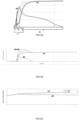
- Figure 2B shows foundation profile 40 on a larger time scale, so that it becomes apparent how the interplay is with the retarder brake profile 10 and combined brake power profile 10+40.
- the initial braking torque that the engine brake can deliver is small but gradually increases over time to braking torques up to 350 kW as shown by profile 10.
- the foundation brake profile 40 provides almost instantaneously a maximum braking torque of 480 kW.
- Figure 2C shows how this reflects in vehicle speed.
- the dashed line represents the vehicle speed with the foundation brakes activated according to the brake profile 40 wherein initially the vehicle speed on the downslope route is lowered. Accordingly the driver does not substantially feel any speeding of the truck when the transmission opens the driveline during the gearshift, which will further improve the experienced braking force.
- the solid speed line 10 shows a scenario where the vehicle speed increases due to insufficient brake power of the engine retarder in the beginning, (in the absence of foundation braking) and accordingly an increase in kinetic energy cannot be prevented sufficiently by the engine retarder 100.
- Figure 3A shows a flow of instructions for activating the engine retarder.
- a driver input is provided, e.g. by activating the engine brake stalk lever.
- the activation signal also provides a set level value for the overall endurance brake, which is provided to the engine brake controller of Figure 1B .
- the set level is provided e.g. by brake profile 40 in combination with a modelled endurance brake performance profile 10, resulting in an overall set brake level 10+40 for brake controller 200.
- Figure 3B shows an exemplary control diagram for implementing the flow of instructions of Figure 3A .
- the set power level (a-EB -set) is inputted with a modifier X into brake controller 200.
- engine retarder 100 and foundation brakes 400 act in combination on vehicle 1 to produce an actual acceleration signal a_veh_act of vehicle 1.
- This signal is inputted in controller 200 and provided to a feedback system where an error value of the set value and actual value is minimized, resulting in an adjusted set value for the foundation brake force F_40 in order to follow the set brake profile 40.
- the feedback system enables the foundation brake force F_40 to be set to zero, if the measured vehicle deceleration a_veh_act appears to follow set deceleration power level without using the foundation brakes without a large error level.
- Figure 4 shows a diagram with additional control parameters for the brake controller in a control architecture for the brake controller 200 with modified elements.
- the control strategy monitors the temperature of the brake system, to make sure that the foundation brakes will never be overheating. In case the temperature of the brake system is above a certain threshold level, the control strategy will report this to the driver (via the HMI) and not use the foundation brakes anymore, so the driver will experience the (slow) transient behaviour of the endurance brake 100 with some vehicle speed increase.
Landscapes
- Engineering & Computer Science (AREA)
- Transportation (AREA)
- Mechanical Engineering (AREA)
- Transmission Of Braking Force In Braking Systems (AREA)
- Regulating Braking Force (AREA)
Abstract
Description
- When driving on a downslope route, commercial vehicles, in particular heavy trucks are provided with an engine retarder system, that e.g. uses the internal combustion engine as a compression brake, by actively controlling intake and exhaust valves and increase back pressure to the engine. Compression braking is a concept known from e.g.
EP1389270 . During compression braking, exhaust valves may be selectively opened to convert, at least temporarily, a power producing internal combustion engine into a power absorbing air compressor. An engine retarder system controls a lift of the exhaust valves, e.g. by a hydraulic actuator. At the beginning of the compression stroke the exhaust valves are opened and high pressurized air from the exhaust manifold flows back into the cylinder which increases the initial pressure during compression by back gas recirculation. Subsequently the exhaust valves close again to increase pressure during the second half of the compression stroke. Near the end of the compression stroke the exhaust valves are opened again dissipating the energy instead of returning it to the drivetrain as positive power during the power stroke; this process is called compression release. This sequence of events can generate high amounts of retarding power, in the order of 300 kW, e.g. 200-400 kW depending on engine speed. - One of the challenges associated with the engine retarder is its typically large response time, since, before compression brake power is fully generated, a time delay occurs of several seconds. First, boost pressure needs to be dropped below a certain level before the brake mode can be selected to prevent too high forces in valve train in brake mode; in addition, hydraulic lag of valve operation system generates a delay, since all specific oil channels have to be filled when brake mode is activated; also settings for the variable turbine geometry (VTG) - if present are adapted. In addition, a downshift of gears, is usually necessary in order to attain a suitable brake power, and then the gradual increase of brake power in conjunction with increasing back pressure of the combustion engine constitutes the engine retarder mode until full brake power is achieved. An existing problem is that a driver often fully engages the engine retarder power to a maximum position which may lead to overshoot once the engine retarder achieves its maximum braking torque. Such an overshoot effect is undesirable as it in facts wastes too much kinetic energy from the vehicle. In case the endurance brake torque is better controllable, the driver probably will use the stalk level more at intermediate positions such that no overshoot will happen. This is good for driveability as well as fuel consumption of the truck.
- An alternative system is a so called 'intarder' which is a hydraulic brake incorporated in the gearbox of the driveline, also called a driveline retarder, and that has a quick response compared to the engine retarder. However, the intarder brake adds to fuel costs since it increases friction by hydraulic drag in the drive line, so creating losses when it is not engaged. Also, the intarder adds to the costs and weight of the manufacturing the vehicle, which are preferably to be reduced. By improving the transient response time of the engine retarder, drivers are brought in a position to better control the amount of braking torque since currently it is difficult for the driver to judge at which position he needs to select the engine retarder level in view of this delay effect.
- The invention aims to provide a solution obviate the problems of the prior art, to increase user comfort, while at the same time optimizing energy consumption.
- In one aspect, it is aimed to provide a system of controlling a vehicle on a downslope route, the vehicle including a combustion engine provided with an engine retarder, and further comprising a brake controller programmed to:
- upon activating, by a driver, the engine retarder, activating, by the brake controller, of the foundation brake in a transient period having a foundation brake profile; wherein
- the foundation brake profile has a first initial phase with a peak brake power that lowers the speed of the vehicle on the downslope route, and wherein
- the foundation brake profile has a second phase that with a brake power lower than the peak brake power and that gradually decreases with a time constant about equal to the increase of engine retarder performance due to buildup of back pressure, to a steady state wherein the vehicle velocity is substantially constant with zero foundation brake power.
- By providing the peak brake power in the first initial phase the speed of the vehicle, in particular, a trailer truck combination on the downslope route, that is initially increased as a consequence of the limited performance of the engine brake and potential downshift, is lowered and vehicle acceleration is prevented in the second phase. Accordingly, the system and corresponding method avoids the use of an additional endurance brake device such as an intarder and the truck becomes more energy efficient due to absence of such brake devices.
- The invention will be further elucidated in the figures:
-
Figure 1A shows a generic setup for a vehicle including a combustion engine provided with an engine retarder; -
Figure 1B shows a brake controller associated with the vehicle ofFigure 1A ; -
Figure 2A relative brake power values over time (arbitrary units) of the foundation brake and the engine retarder; -
Figure 2B shows a foundation brake profile on a larger time scale; -
Figure 2C shows a vehicle speed curve with and without the brake foundation brake; -
Figure 3A shows a flow of instructions for activating the engine retarder; -
Figure 3B shows a control diagram for implementing the flow of instructions ofFigure 3A ; -
Figure 4 shows a diagram with additional control parameters for the brake controller - Unless otherwise defined, all terms (including technical and scientific terms) used herein have the same meaning as commonly understood by one of ordinary skill in the art to which this disclosure belongs as read in the context of the description and drawings. It will be further understood that terms, such as those defined in commonly used dictionaries, should be interpreted as having a meaning that is consistent with their meaning in the context of the relevant art and will not be interpreted in an idealized or overly formal sense unless expressly so defined herein. In some instances, detailed descriptions of well-known devices and methods may be omitted so as not to obscure the description of the present systems and methods. Terminology used for describing particular embodiments is not intended to be limiting of the invention. As used herein, the singular forms "a", "an" and "the" are intended to include the plural forms as well, unless the context clearly indicates otherwise. The term "and/or" includes any and all combinations of one or more of the associated listed items. It will be further understood that the terms "comprises" and/or "comprising" specify the presence of stated features but do not preclude the presence or addition of one or more other features. All publications, patent applications, patents, and other references mentioned herein are incorporated by reference in their entirety. In case of conflict, the present specification, including definitions, will control.
-
Figure 1A shows a generic setup for avehicle 1 including a combustion engine provided with anengine retarder 100, which is a specific function of the engine including structure that will not be described in the detailed description since it is known conventionally and has certain features, that provides a response as described in the introduction and will be further elaborated below. For ease of understanding thevehicle 1 has a velocity V and adriveline 15, that includes a clutch and atransmission 300. In a conventional setup, thetransmission 300 may be equipped with an driveline retarder system, which is a hydraulic brake with a brake response that will be described below and is known to the skilled person. Furthermore, thevehicle 1 is equipped withfoundation brakes 400, that brake the wheels and are typically provided through brake pads and disc brakes. The classical idea behind of endurance braking is not to use the foundation brakes and save money on service cost (so to extend the lifetime of the brake pads and disc brakes). According to this invention the foundation brakes are activated in the initial phase of braking, and a well-balanced trade-off is made between a good initial braking response versus extra wear for the service brakes. -
Figure 1B in more detail shows a brake controller according to an aspect of the invention, that controls the foundation brakes as part of an endurance brake controller. To thisend brake controller 200 has inputs, in particular aninput 21 for activating, by a driver, the engine retarder and thereby activating, by thebrake controller 200, offoundation brakes 400 in a transient period according to a foundation brake profile. Suitable inputs can be a stalk, typically known as a brake retarder stalk with a variety of functions, in particular, an on/off function and in the on- position a variable endurance brake level, e.g. a low endurance brake level (e.g. 30 % of maximum endurance brake power), a medium endurance brake level (e.g. 60% of maximum endurance brake power) and maximum endurance brake level. - The
brake controller 200 calculates, dependent on the stalk position, an amount of initial brake torque from the foundation brakes. For example, if the driver selectsposition 1, the system aims to deliver e.g. 33% of the maximum brake torque. With position 2, e.g. 66% is delivered and with position 3 it will be 100%. These values can be calibrated according to the max. brake torque that the engine retarder 100 delivers and which can also depend on the actual vehicle speed and selected gear. - Accordingly,
brake controller 200 receives a brake request and preferably accompanied with a set torque level / set deceleration level in a feed forward mode. In addition,brake controller 200 receives alsospeed monitoring data 22 andvehicle parameter data 23, further elaborated inFigure 4 . - As a result to the driver
activation brake controller 200 outputsactivation control signals 45 to the engine retarder 100, as is conventional and will not be further described. In addition, according to theinvention brake controller 200 outputs foundation brake activation control signals 40 tofoundation brakes 400 in a transient period as will be further described according to afoundation brake profile 40. - In more detail the
foundation brake profile 40 is discussed inFigure 2 . InFigure 2A relative brake power values over time (arbitrary units) of thefoundation brake 400 as afoundation brake profile 40.Foundation brake profile 40 has that has a first initial phase I with a peak brake power that lowers the speed of the vehicle on the downslope route. The peak brake power can be typically in a range e.g. the peak brake power may exceed, for at least one selected engine retarder power mode, 350 kW, preferably 480 kW. This peak brake power is typically not dependent on vehicle mass but may be tuned in duration of the first phase that can be shortened or lengthened. The first phase is roughly determined by the activation time for activating theengine retarder 100, resulting in engineretarder power profile 10, that typically has a delay phase i. A typical time of the delay phase takes about 0.5 -2 seconds, e.g. 1 second, a startup phase (ii) wherein no backpressure is present (0.5-2 seconds), and a build up phase (iii), where the back pressure builds up (2-3 seconds). The initial phase I can characterized by the delay phase i, the startup phase ii, and the buildup phase iii, where the back pressure builds up to about 30-60 % of the requested brake power about 0.5 -2 seconds after the initial activation. - The foundation brake profile may be dependent on a selected power mode of the engine retarder.
- For instance, it is possible to have a number of selected power modes, e.g. in increasing power and have the first power mode not provided with a brake profile for the foundation brakes, and subsequent power modes provided with a brake profile. A driver will then, based on experience be able to select a desired power mode for the engine retarder, with a corresponding desired brake profile, that may be stronger or less strong based on the actual driving condition. To provide for a selectable foundation brake profile will in practice be more energy efficient than a selectable power mode of the engine retarder, since it will be less likely that the driver selects a too strong engine brake power level, if in the lower phase a substantial deceleration can be provide by the foundation brake profile as described herein.
- In addition, the first initial phase I may overlap with an initial build up phase iii phase of the
engine retarder 100. - In the subsequent second phase II of the
brake profile 40 the foundation brake power is lowered and gradually decreases with a time constant about equal to the increase of engine retarder performance due to buildup of back pressure, to a steady state wherein the vehicle velocity is substantially constant with zero foundation brake power, e.g. in a time frame of about 2-4 seconds. Typically the first phase takes about 15-25% of the time of the foundation brake event. - Extra wear of the foundation brakes might result in a modified shape/calibration of the
foundation brake profile 40, wherein peak brake power is smoothened into a less steep curve. Also, the first and second phase may dependent and differ from each other for a selected engine retarder power mode. Additionally, the peak brake power may be set in accordance with a slope angle, vehicle mass, or retarder power setting or another control feature (seeFig 4 ). -
Figure 2B showsfoundation profile 40 on a larger time scale, so that it becomes apparent how the interplay is with theretarder brake profile 10 and combinedbrake power profile 10+40. - The initial braking torque that the engine brake can deliver is small but gradually increases over time to braking torques up to 350 kW as shown by
profile 10. As an exemplary example, thefoundation brake profile 40 provides almost instantaneously a maximum braking torque of 480 kW.Figure 2C shows how this reflects in vehicle speed. The dashed line represents the vehicle speed with the foundation brakes activated according to thebrake profile 40 wherein initially the vehicle speed on the downslope route is lowered. Accordingly the driver does not substantially feel any speeding of the truck when the transmission opens the driveline during the gearshift, which will further improve the experienced braking force. - One can observe that the engine brake needs time to build-up its brake torque, but ultimately on a long downhill it will reach a braking torque sufficient for keeping the vehicle at constant speed. The
solid speed line 10 shows a scenario where the vehicle speed increases due to insufficient brake power of the engine retarder in the beginning, (in the absence of foundation braking) and accordingly an increase in kinetic energy cannot be prevented sufficiently by theengine retarder 100. -
Figure 3A shows a flow of instructions for activating the engine retarder. Initially a driver input is provided, e.g. by activating the engine brake stalk lever. This results in an activation signal S for the engine brake 100 (F_EngBr_set) which can depend on a requested engine brake power level. The activation signal also provides a set level value for the overall endurance brake, which is provided to the engine brake controller ofFigure 1B . The set level is provided e.g. bybrake profile 40 in combination with a modelled endurancebrake performance profile 10, resulting in an overallset brake level 10+40 forbrake controller 200. -
Figure 3B shows an exemplary control diagram for implementing the flow of instructions ofFigure 3A . The set power level (a-EB -set) is inputted with a modifier X intobrake controller 200. As a result,engine retarder 100 andfoundation brakes 400 act in combination onvehicle 1 to produce an actual acceleration signal a_veh_act ofvehicle 1. This signal is inputted incontroller 200 and provided to a feedback system where an error value of the set value and actual value is minimized, resulting in an adjusted set value for the foundation brake force F_40 in order to follow theset brake profile 40. The feedback system enables the foundation brake force F_40 to be set to zero, if the measured vehicle deceleration a_veh_act appears to follow set deceleration power level without using the foundation brakes without a large error level. -
Figure 4 shows a diagram with additional control parameters for the brake controller in a control architecture for thebrake controller 200 with modified elements. The control strategy monitors the temperature of the brake system, to make sure that the foundation brakes will never be overheating. In case the temperature of the brake system is above a certain threshold level, the control strategy will report this to the driver (via the HMI) and not use the foundation brakes anymore, so the driver will experience the (slow) transient behaviour of theendurance brake 100 with some vehicle speed increase. - While example embodiments are shown for systems and methods, also alternative ways may be envisaged by those skilled in the art having the benefit of the present disclosure for achieving a similar function and result. E.g. some components may be combined or split up into one or more alternative components. Finally, these embodiments are intended to be merely illustrative of the present system and should not be construed as limiting the appended claims to any particular embodiment or group of embodiments. Thus, while the present system has been described in particular detail with reference to specific exemplary embodiments thereof, it should also be appreciated that numerous modifications and alternative embodiments may be devised by those having ordinary skill in the art without departing from the scope of the present systems and methods as set forth in the claims that follow. The specification and drawings are accordingly to be regarded in an illustrative manner and are not intended to limit the scope of the appended claims.
Claims (16)
- A system of controlling a vehicle on a downslope route, the vehicle including a combustion engine provided with an engine retarder, and further comprising a brake controller programmed to:- upon activating, by a driver, the engine retarder, activating, by the brake controller, of a foundation brake in a transient period according to a foundation brake profile; wherein∘ the foundation brake profile has a first initial phase with a peak brake power that lowers the speed of the vehicle on the downslope route, and wherein∘ the foundation brake profile has a second phase that with a brake power lower than the peak brake power and that gradually decreases with a time constant about equal to the increase of engine retarder performance due to buildup of back pressure, to a steady state wherein the vehicle velocity is substantially constant with zero foundation brake power.
- The system according to claim 1, wherein the foundation brake profile is dependent on a selected power mode of the engine retarder.
- A system according to any preceding claim, wherein the first initial phase overlaps with an initial phase of the engine retarder.
- A system according to any preceding claim, wherein the first and/or second phase are dependent on a selected engine retarder power mode.
- A system according to any preceding claim, wherein the peak brake power exceeds, for at least one selected engine retarder power mode, 350 kW, preferably 480 kW.
- A system according to any preceding claim, wherein the brake controller registers the vehicle acceleration and controls a calculated foundation brake profile as foundation brake set point that activated to a non-zero value and that is adjusted in a feedback loop in accordance with the registered vehicle acceleration.
- A system according to claim 6, wherein the set point is set to a zero-valu in a condition of thermal overload of the foundation brake.
- A system according to any preceding claim, wherein the peak brake power is set in accordance with a slope angle, vehicle mass and retarder power setting.
- A system according to any preceding claim, which is part of a cruise control system.
- A vehicle including a system according to any preceding claim.
- A method of controlling a vehicle on a downslope route, the vehicle including a combustion engine provided with an engine retarder, comprising:- upon activating, by a driver, the engine retarder, automatically activating the foundation brake in a transient period having a foundation brake profile; wherein∘ the foundation brake profile has a first initial phase with a peak brake power that lowers the speed of the vehicle on the downslope route, and wherein∘ the foundation brake profile has a second phase that with a brake power lower than the peak brake power and that gradually decreases with a time constant about equal to the increase of engine retarder performance due to buildup of back pressure, to a steady state wherein the vehicle velocity is substantially constant with zero foundation brake power.
- The method according to claim 11, wherein the foundation brake profile is dependent on a selected power mode the engine retarder.
- A method according to any preceding claims 11-12, wherein the first initial phase overlaps with an initial phase of the engine retarder.
- A method according to any preceding claim 11-13, wherein a calculated foundation brake profile is used as foundation brake set point that is activated to a non-zero value and that is adjusted in a feedback loop in accordance with the registered vehicle acceleration.
- A method according to any preceding claim 11-14, wherein the peak brake power is set in accordance with a slope angle.
- A computer program product, implemented on computer-readable non-transitory storage medium, the computer program product configured for, when run on a computer, executing the method steps according to any one of claims 11-15.
Applications Claiming Priority (1)
| Application Number | Priority Date | Filing Date | Title |
|---|---|---|---|
| NL2032348A NL2032348B1 (en) | 2022-07-01 | 2022-07-01 | Method and system of controlling a vehicle on a downslope route |
Publications (3)
| Publication Number | Publication Date |
|---|---|
| EP4299393A1 true EP4299393A1 (en) | 2024-01-03 |
| EP4299393C0 EP4299393C0 (en) | 2026-02-25 |
| EP4299393B1 EP4299393B1 (en) | 2026-02-25 |
Family
ID=83270996
Family Applications (1)
| Application Number | Title | Priority Date | Filing Date |
|---|---|---|---|
| EP23182717.1A Active EP4299393B1 (en) | 2022-07-01 | 2023-06-30 | Method and system of controlling a vehicle on a downslope route |
Country Status (2)
| Country | Link |
|---|---|
| EP (1) | EP4299393B1 (en) |
| NL (1) | NL2032348B1 (en) |
Citations (5)
| Publication number | Priority date | Publication date | Assignee | Title |
|---|---|---|---|---|
| EP1389270A1 (en) | 2001-05-22 | 2004-02-18 | Diesel Engine Retarders, Inc. | Method and system for engine braking in an internal combustion engine |
| WO2010059108A1 (en) * | 2008-11-21 | 2010-05-27 | Scania Cv Ab (Publ) | Brake feedback system |
| US20120089313A1 (en) * | 2010-10-12 | 2012-04-12 | Bendix Commercial Vehicle Systems Llc | System and method for reducing brake fade |
| WO2015197092A1 (en) * | 2014-06-27 | 2015-12-30 | Volvo Truck Corporation | An arrangement and method for a cruise control brake in a vehicle |
| WO2015197084A1 (en) * | 2014-06-24 | 2015-12-30 | Volvo Truck Corporation | An arrangement and method for supporting a cruise control brake in a vehicle |
-
2022
- 2022-07-01 NL NL2032348A patent/NL2032348B1/en active
-
2023
- 2023-06-30 EP EP23182717.1A patent/EP4299393B1/en active Active
Patent Citations (5)
| Publication number | Priority date | Publication date | Assignee | Title |
|---|---|---|---|---|
| EP1389270A1 (en) | 2001-05-22 | 2004-02-18 | Diesel Engine Retarders, Inc. | Method and system for engine braking in an internal combustion engine |
| WO2010059108A1 (en) * | 2008-11-21 | 2010-05-27 | Scania Cv Ab (Publ) | Brake feedback system |
| US20120089313A1 (en) * | 2010-10-12 | 2012-04-12 | Bendix Commercial Vehicle Systems Llc | System and method for reducing brake fade |
| WO2015197084A1 (en) * | 2014-06-24 | 2015-12-30 | Volvo Truck Corporation | An arrangement and method for supporting a cruise control brake in a vehicle |
| WO2015197092A1 (en) * | 2014-06-27 | 2015-12-30 | Volvo Truck Corporation | An arrangement and method for a cruise control brake in a vehicle |
Also Published As
| Publication number | Publication date |
|---|---|
| NL2032348B1 (en) | 2024-01-18 |
| EP4299393C0 (en) | 2026-02-25 |
| EP4299393B1 (en) | 2026-02-25 |
Similar Documents
| Publication | Publication Date | Title |
|---|---|---|
| US6287237B1 (en) | Method of controlling the drive train of a motor vehicle and drive train controller of a motor vehicle | |
| US10155511B2 (en) | Opportunistic charging of hybrid vehicle battery | |
| JP2005500944A (en) | Shift control method for use in an automated manual transmission coupled to a turbocharged internal combustion engine | |
| US9181885B2 (en) | Method for controlling the locomotion of a motor vehicle | |
| CN103108789B (en) | Method for gear shift control of a motor vehicle | |
| US6128564A (en) | Controller for a drive train of a motor vehicle | |
| CN106671972B (en) | Shift control method of hybrid vehicle having dual clutch transmission | |
| JPS6018862B2 (en) | Gearbox for load switching transmission | |
| US9505394B2 (en) | Method and device for changing the mechanical coupling of a drive unit to a power train of a motor vehicle, whose power train is equipped with at least two drive units | |
| US20060230920A1 (en) | Hydrostatic transmission | |
| EP1446305B1 (en) | Gear box for motor vehicles | |
| CN102348881B (en) | Drive source control device and control method | |
| CN108025639B (en) | Drivetrain implementing automatic direction change braking | |
| US9789864B2 (en) | Devices and methods for distributing an overall target torque specification | |
| US7225059B2 (en) | Method for operating a motor vehicle | |
| US20080262693A1 (en) | Method for controlling the desired speed in an overrun condition for a vehicle comprising a retarder | |
| US6090010A (en) | System for adapting the braking moment of a primary system as a function of the gear speed setting | |
| EP1638831B1 (en) | Motor vehicle with auxiliary brake and method to control speed change during shifting such a vehicle | |
| EP4299393B1 (en) | Method and system of controlling a vehicle on a downslope route | |
| US8005601B2 (en) | Method and control unit for damping load impacts with an open torque converter lockup clutch | |
| CN110087961A (en) | The speed control of vehicle | |
| RU2017121023A (en) | System and method for controlling a torque converter clutch | |
| GB2517816B (en) | A method for limiting the amount of energy dissipated in a friction clutch during engagement of the clutch | |
| US5924959A (en) | Device for controlling an automatic transmission and an engine for vehicles | |
| CN111572532A (en) | Vehicle exhaust sound control system and method |
Legal Events
| Date | Code | Title | Description |
|---|---|---|---|
| PUAI | Public reference made under article 153(3) epc to a published international application that has entered the european phase |
Free format text: ORIGINAL CODE: 0009012 |
|
| STAA | Information on the status of an ep patent application or granted ep patent |
Free format text: STATUS: THE APPLICATION HAS BEEN PUBLISHED |
|
| AK | Designated contracting states |
Kind code of ref document: A1 Designated state(s): AL AT BE BG CH CY CZ DE DK EE ES FI FR GB GR HR HU IE IS IT LI LT LU LV MC ME MK MT NL NO PL PT RO RS SE SI SK SM TR |
|
| STAA | Information on the status of an ep patent application or granted ep patent |
Free format text: STATUS: REQUEST FOR EXAMINATION WAS MADE |
|
| 17P | Request for examination filed |
Effective date: 20240702 |
|
| RBV | Designated contracting states (corrected) |
Designated state(s): AL AT BE BG CH CY CZ DE DK EE ES FI FR GB GR HR HU IE IS IT LI LT LU LV MC ME MK MT NL NO PL PT RO RS SE SI SK SM TR |
|
| RIC1 | Information provided on ipc code assigned before grant |
Ipc: B60T 8/17 20060101AFI20250814BHEP Ipc: B60T 13/58 20060101ALI20250814BHEP |
|
| GRAP | Despatch of communication of intention to grant a patent |
Free format text: ORIGINAL CODE: EPIDOSNIGR1 |
|
| STAA | Information on the status of an ep patent application or granted ep patent |
Free format text: STATUS: GRANT OF PATENT IS INTENDED |
|
| INTG | Intention to grant announced |
Effective date: 20250924 |
|
| GRAS | Grant fee paid |
Free format text: ORIGINAL CODE: EPIDOSNIGR3 |
|
| GRAA | (expected) grant |
Free format text: ORIGINAL CODE: 0009210 |
|
| STAA | Information on the status of an ep patent application or granted ep patent |
Free format text: STATUS: THE PATENT HAS BEEN GRANTED |
|
| AK | Designated contracting states |
Kind code of ref document: B1 Designated state(s): AL AT BE BG CH CY CZ DE DK EE ES FI FR GB GR HR HU IE IS IT LI LT LU LV MC ME MK MT NL NO PL PT RO RS SE SI SK SM TR |
|
| REG | Reference to a national code |
Ref country code: CH Ref legal event code: F10 Free format text: ST27 STATUS EVENT CODE: U-0-0-F10-F00 (AS PROVIDED BY THE NATIONAL OFFICE) Effective date: 20260225 Ref country code: GB Ref legal event code: FG4D |
|
| REG | Reference to a national code |
Ref country code: DE Ref legal event code: R096 Ref document number: 602023012477 Country of ref document: DE |
|
| REG | Reference to a national code |
Ref country code: IE Ref legal event code: FG4D |
|
| U01 | Request for unitary effect filed |
Effective date: 20260313 |
|
| U07 | Unitary effect registered |
Designated state(s): AT BE BG DE DK EE FI FR IT LT LU LV MT NL PT RO SE SI Effective date: 20260318 |
|
| PG25 | Lapsed in a contracting state [announced via postgrant information from national office to epo] |
Ref country code: RS Free format text: LAPSE BECAUSE OF FAILURE TO SUBMIT A TRANSLATION OF THE DESCRIPTION OR TO PAY THE FEE WITHIN THE PRESCRIBED TIME-LIMIT Effective date: 20260525 |
|
| PG25 | Lapsed in a contracting state [announced via postgrant information from national office to epo] |
Ref country code: ES Free format text: LAPSE BECAUSE OF FAILURE TO SUBMIT A TRANSLATION OF THE DESCRIPTION OR TO PAY THE FEE WITHIN THE PRESCRIBED TIME-LIMIT Effective date: 20260225 |
|
| PG25 | Lapsed in a contracting state [announced via postgrant information from national office to epo] |
Ref country code: PL Free format text: LAPSE BECAUSE OF FAILURE TO SUBMIT A TRANSLATION OF THE DESCRIPTION OR TO PAY THE FEE WITHIN THE PRESCRIBED TIME-LIMIT Effective date: 20260225 |
|
| PG25 | Lapsed in a contracting state [announced via postgrant information from national office to epo] |
Ref country code: GR Free format text: LAPSE BECAUSE OF FAILURE TO SUBMIT A TRANSLATION OF THE DESCRIPTION OR TO PAY THE FEE WITHIN THE PRESCRIBED TIME-LIMIT Effective date: 20260526 |
|
| PG25 | Lapsed in a contracting state [announced via postgrant information from national office to epo] |
Ref country code: NO Free format text: LAPSE BECAUSE OF FAILURE TO SUBMIT A TRANSLATION OF THE DESCRIPTION OR TO PAY THE FEE WITHIN THE PRESCRIBED TIME-LIMIT Effective date: 20260525 |
|
| PG25 | Lapsed in a contracting state [announced via postgrant information from national office to epo] |
Ref country code: HR Free format text: LAPSE BECAUSE OF FAILURE TO SUBMIT A TRANSLATION OF THE DESCRIPTION OR TO PAY THE FEE WITHIN THE PRESCRIBED TIME-LIMIT Effective date: 20260225 |
|
| PG25 | Lapsed in a contracting state [announced via postgrant information from national office to epo] |
Ref country code: IS Free format text: LAPSE BECAUSE OF FAILURE TO SUBMIT A TRANSLATION OF THE DESCRIPTION OR TO PAY THE FEE WITHIN THE PRESCRIBED TIME-LIMIT Effective date: 20260625 |
|
| U20 | Renewal fee for the european patent with unitary effect paid |
Year of fee payment: 4 Effective date: 20260629 |