EP4299389A1 - Curved structure for a work vehicle - Google Patents
Curved structure for a work vehicle Download PDFInfo
- Publication number
- EP4299389A1 EP4299389A1 EP23176132.1A EP23176132A EP4299389A1 EP 4299389 A1 EP4299389 A1 EP 4299389A1 EP 23176132 A EP23176132 A EP 23176132A EP 4299389 A1 EP4299389 A1 EP 4299389A1
- Authority
- EP
- European Patent Office
- Prior art keywords
- curved
- support
- work vehicle
- curved structure
- curved support
- Prior art date
- Legal status (The legal status is an assumption and is not a legal conclusion. Google has not performed a legal analysis and makes no representation as to the accuracy of the status listed.)
- Pending
Links
Images







Classifications
-
- B—PERFORMING OPERATIONS; TRANSPORTING
- B60—VEHICLES IN GENERAL
- B60R—VEHICLES, VEHICLE FITTINGS, OR VEHICLE PARTS, NOT OTHERWISE PROVIDED FOR
- B60R21/00—Arrangements or fittings on vehicles for protecting or preventing injuries to occupants or pedestrians in case of accidents or other traffic risks
- B60R21/02—Occupant safety arrangements or fittings, e.g. crash pads
- B60R21/11—Overhead guards, e.g. against loads falling down
-
- B—PERFORMING OPERATIONS; TRANSPORTING
- B60—VEHICLES IN GENERAL
- B60J—WINDOWS, WINDSCREENS, NON-FIXED ROOFS, DOORS, OR SIMILAR DEVICES FOR VEHICLES; REMOVABLE EXTERNAL PROTECTIVE COVERINGS SPECIALLY ADAPTED FOR VEHICLES
- B60J1/00—Windows; Windscreens; Accessories therefor
- B60J1/02—Windows; Windscreens; Accessories therefor arranged at the vehicle front, e.g. structure of the glazing, mounting of the glazing
-
- B—PERFORMING OPERATIONS; TRANSPORTING
- B60—VEHICLES IN GENERAL
- B60J—WINDOWS, WINDSCREENS, NON-FIXED ROOFS, DOORS, OR SIMILAR DEVICES FOR VEHICLES; REMOVABLE EXTERNAL PROTECTIVE COVERINGS SPECIALLY ADAPTED FOR VEHICLES
- B60J1/00—Windows; Windscreens; Accessories therefor
- B60J1/008—Windows; Windscreens; Accessories therefor of special shape, e.g. beveled edges, holes for attachment, bent windows, peculiar curvatures such as when being integrally formed with roof, door, etc.
-
- B—PERFORMING OPERATIONS; TRANSPORTING
- B60—VEHICLES IN GENERAL
- B60R—VEHICLES, VEHICLE FITTINGS, OR VEHICLE PARTS, NOT OTHERWISE PROVIDED FOR
- B60R21/00—Arrangements or fittings on vehicles for protecting or preventing injuries to occupants or pedestrians in case of accidents or other traffic risks
- B60R21/02—Occupant safety arrangements or fittings, e.g. crash pads
- B60R21/13—Roll-over protection
- B60R21/131—Protective devices for drivers in case of overturning of tractors
Definitions
- the present disclosure relates to a curved structure for a work vehicle.
- Work vehicles can include curved structures near a vehicle operator. These structures can include roll over protection systems or ROPS. Many of these structures are positioned behind the operator seat.
- ROPS roll over protection systems
- a curved structure for a work vehicle includes a first curved support extending a length, a second curved support extending a length, the second curved support spaced apart a width from the first curved support, and a curved windshield positioned between and connected to the first and second curved supports.
- the curved structure can include a top support connected near an end of the first curved support and an end of the second curved support.
- the first curved support, the second curved support, and the top support can be a single piece.
- the curved windshield can extend upward and rearward beyond a front portion of a seat in the work vehicle.
- the curved structure can include a first base portion configured to mount to a chassis of the work vehicle, the first base portion positioned near an end of the first curved support, and a second base portion configured to mount to a chassis of the work vehicle, the second base portion positioned near an end of the second curved support.
- the first and second base portions can be configured to attach to a chassis of the work vehicle at a position forward of a steering wheel of the work vehicle.
- the curved structure can include a first rear support connected near an end of the first support and to the work vehicle, and a second rear support connected near an end of the second support and to the work vehicle.
- An angle of an arc formed by the first curved support can be greater than forty-five degrees.
- An angle of an arc formed by the first curved support can be greater than seventy-five degrees.
- An angle of an arc formed by the first curved support can be less than one hundred thirty-five degrees.
- An angle of an arc formed by the first curved support can be less than one hundred twenty degrees.
- a work vehicle having a curved structure includes a first curved support extending a length, a second curved support extending a length, the second curved support spaced apart a width from the first curved support, and a curved windshield positioned between and connected to the first and second curved supports.
- the work vehicle can include a top support connected near an end of the first curved support and an end of the second curved support.
- the first curved support, the second curved support, and the top support can be a single piece.
- the curved windshield can extend upward and rearward beyond a front portion of a seat in the work vehicle.
- the work vehicle can include a first base portion attached to a chassis of the work vehicle, the first base portion positioned near an end of the first curved support, and a second base portion attached to a chassis of the work vehicle, the second base portion positioned near an end of the second curved support.
- the first and second base portions can be attached to a chassis of the work vehicle at a position forward of a steering wheel of the work vehicle.
- the work vehicle can include a first rear support connected near an end of the first support and to the work vehicle, and a second rear support connected near an end of the second support and to the work vehicle.
- An angle of an arc formed by the first curved support can be between sixty and one hundred twenty degrees.
- An angle of an arc formed by the first curved support can be between seventy-five and one hundred five degrees.
- a curved structure 120 can be attached or installed on a work vehicle 100, such as a tractor.
- the present disclosure also applies to other types of work vehicles in agriculture, construction, road building, forestry, utility, turf, and lawn care.
- the work vehicle 100 can includes an open operator station 102 having various devices and controls to operate the work vehicle 100.
- the work vehicle 100 includes a hood 104, one or more ground engaging apparatus 106, a power source 108, and a frame or chassis 110.
- the work vehicle 100 includes a seat 112.
- the curved structure 120 can include a first support 122, a second support 124 spaced apart a width Wi from the first support 122, and a windscreen or windshield 140 positioned between and connected to the first and second supports 122, 124.
- the first and second supports 122, 124 can each be arcuate or curvilinear and extend a length Li.
- the windshield 140 can be curvilinear or curved and extend a width W 2 and a length L 2 .
- the windshield 140 can have a shorter length L 2 than the length Li of the first and second supports 122, 124.
- the windshield 140 can have a larger width W 2 than the width Wi of the space between the first and second supports 122, 124.
- the windshield 140 can include a frame 142 surrounding at least a portion of the windshield 140.
- the curved structure 120 can include a top support 126 connected near an end of the first support 122 and near an end of the second support 124.
- the end of the first support 122 and the end of the second support 124 can curve inwards towards each other.
- the top support 126 can connect the inwardly curving ends of the first and second supports 122, 124.
- the first curved support 122, the second curved support 124, and the top support 126 are a single or unitary piece or part.
- the curved structure 120 can include a curvilinear or curved transition between the first support 122 and the top support 126 and between the second support 124 and the top support 126.
- the frame 142 can have one or more connectors 144 to connect or attach the windshield 140 to one or more of the first, second, and top supports 122, 124, 126. using fasteners, for example.
- the other ends of the first and second supports 122, 124 can include first and second base portions 130, 132 configured to mount to a frame or chassis 110 of a work vehicle 100.
- the first support 122, the second support 124, or both can form an arc having an angle A of any size, dimension, or range.
- the first and second supports 122, 124 and the windshield 140 can have a similar or the same curvilinear shape or radius of curvature, which can be fixed or variable.
- an angle A of an arc formed by the first support 122 is greater than forty-five degrees (45°), greater than seventy-five degrees (75°), or greater than ninety degrees (90°).
- an angle A of an arc formed by the first curved support 122 is less than one hundred thirty-five degrees (135°), less than one hundred twenty degrees (120°), less than one hundred degrees (100°), or less than ninety degrees (90°).
- an angle A of an arc formed by the first support 122 is between sixty and one hundred twenty degrees (60°-120°), between seventy-five and one hundred five degrees (75°-105°), or between eighty and one hundred degrees (80°-100°).
- the curved structure 120 can connect to the work vehicle 100 at a position or location forward of the operator station 102.
- the first and second base portions 130, 132 of the curved structure 120 can include fasteners 138 to attach to the work vehicle 100.
- the first and second base portions 130, 132 can attach to frame or chassis 110 of the work vehicle 100 at a position or location forward of a steering wheel 114 of the work vehicle 100.
- a top portion of the curved structure 120 can extend upward and rearward beyond a front portion of a seat 112 in the work vehicle 100.
- the windshield 140 can extend vertically and horizontally beyond a front portion of a seat 112 in the work vehicle 100.
- the top portion of the curved structure 120 and the windshield 140 can extend upward and rearward beyond a majority of the seat 112, as shown for example in FIGURE 2 .
- one or more rear supports 150, 152 can connect to the curved support 120 and to the work vehicle 100.
- the curved structure 120 can include a first rear support 150 connected near an end of the first support 122 and to the work vehicle 100.
- the curved structure 120 can include a second rear support 152 connected near an end of the second support 124 and to the work vehicle 100.
- the first and second rear supports 150, 152 can connect to the top support 126 or to the transitions between the top support 126 and the first and second supports 122, 124.
- the first and second rear supports 150, 152 can be angled forward from the work vehicle 100 to the curved structure 120, as shown.
- the first and second rear supports 150, 152 can be angled rearward from the work vehicle 100 to the curved structure 120, or the first and second rear supports 150, 152 can extend substantially vertical from the work vehicle 100 to the curved structure 120.
- a curved support 120 can connect to a rear support 160 attached to the work vehicle 100.
- the rear support 160 can be substantially vertical.
- the rear support 160 can be in the form of a roll bar.
- the rear support 160 can extend above the curved support 120.
- the first and second supports 122, 124 can extend rearward to the rear support 160.
- the first and second supports 122, 124 can connect to the rear support 160.
- the windshield 140 can extend to the rear support 160 or there can be a selected distance 162 between the windshield 140 and the rear support 160 forming an opening between the windshield 140 and the rear support 160.
- the curved support 120 can include a top support 126. According to some implementations, the top support 126 is an optional support member.
- the curved structure 120 When the curved structure 120 is installed on a work vehicle 100, the curved structure 120 can provide a barrier against vegetation (e.g., limbs, branches, bushes, or shrubs) from contacting an operator of the work vehicle 100. The curved structure 120 can prevent vegetation extending within a boundary of the work vehicle 100 from entering the open operator station 102. The curved structure 120 also allows extensive visibility of the operating area surrounding the work vehicle 100. During forward operation of the work vehicle 100, the curved structure 120 can guide vegetation up and over the open operator station 102 and the operator of the work vehicle 100. The curved structure 120 can also function as a roll over protection system, or roll over protective structure, referred to as ROPS.
- ROPS roll over protection system
- At least one of A, B, and C indicates the possibilities of only A, only B, only C, or any combination of two or more of A, B, and C (e.g., A and B; B and C; A and C; or A, B, and C).
Landscapes
- Engineering & Computer Science (AREA)
- Mechanical Engineering (AREA)
- Body Structure For Vehicles (AREA)
Abstract
Description
- The present disclosure relates to a curved structure for a work vehicle.
- Work vehicles can include curved structures near a vehicle operator. These structures can include roll over protection systems or ROPS. Many of these structures are positioned behind the operator seat.
- According to an aspect of the present disclosure, a curved structure for a work vehicle includes a first curved support extending a length, a second curved support extending a length, the second curved support spaced apart a width from the first curved support, and a curved windshield positioned between and connected to the first and second curved supports.
- The curved structure can include a top support connected near an end of the first curved support and an end of the second curved support.
- The first curved support, the second curved support, and the top support can be a single piece.
- The curved windshield can extend upward and rearward beyond a front portion of a seat in the work vehicle.
- The curved structure can include a first base portion configured to mount to a chassis of the work vehicle, the first base portion positioned near an end of the first curved support, and a second base portion configured to mount to a chassis of the work vehicle, the second base portion positioned near an end of the second curved support.
- The first and second base portions can be configured to attach to a chassis of the work vehicle at a position forward of a steering wheel of the work vehicle.
- The curved structure can include a first rear support connected near an end of the first support and to the work vehicle, and a second rear support connected near an end of the second support and to the work vehicle.
- An angle of an arc formed by the first curved support can be greater than forty-five degrees.
- An angle of an arc formed by the first curved support can be greater than seventy-five degrees.
- An angle of an arc formed by the first curved support can be less than one hundred thirty-five degrees.
- An angle of an arc formed by the first curved support can be less than one hundred twenty degrees.
- According to an aspect of the present disclosure, a work vehicle having a curved structure includes a first curved support extending a length, a second curved support extending a length, the second curved support spaced apart a width from the first curved support, and a curved windshield positioned between and connected to the first and second curved supports.
- The work vehicle can include a top support connected near an end of the first curved support and an end of the second curved support.
- The first curved support, the second curved support, and the top support can be a single piece.
- The curved windshield can extend upward and rearward beyond a front portion of a seat in the work vehicle.
- The work vehicle can include a first base portion attached to a chassis of the work vehicle, the first base portion positioned near an end of the first curved support, and a second base portion attached to a chassis of the work vehicle, the second base portion positioned near an end of the second curved support.
- The first and second base portions can be attached to a chassis of the work vehicle at a position forward of a steering wheel of the work vehicle.
- The work vehicle can include a first rear support connected near an end of the first support and to the work vehicle, and a second rear support connected near an end of the second support and to the work vehicle.
- An angle of an arc formed by the first curved support can be between sixty and one hundred twenty degrees.
- An angle of an arc formed by the first curved support can be between seventy-five and one hundred five degrees.
- The above and other features will become apparent from the following detailed description and accompanying drawings.
- The detailed description of the drawings refers to the accompanying figures in which:
-
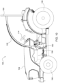
FIGURE 1 is a perspective view of a work vehicle including a curved structure, according to an implementation; -
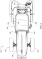
FIGURE 2 is a top perspective view of a work vehicle including a curved structure, according to an implementation; -
FIGURE 3 is a side perspective view of a work vehicle including a curved structure, according to an implementation; -
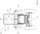
FIGURE 4 is a front perspective view of a work vehicle including a curved structure, according to an implementation; -
FIGURE 5 is a perspective view of a curved structure, according to an implementation; -
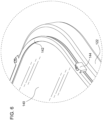
FIGURE 6 is a detail view of a curved structure, according to an implementation; -
FIGURE 7 is a side perspective view of a curved structure, according to an implementation; -
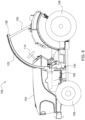
FIGURE 8 is a side perspective view of a work vehicle including a curved structure, according to an implementation; -
FIGURE 9 is a top perspective view of a work vehicle including a curved structure, according to an implementation; -
FIGURE 10 is a side perspective view of a work vehicle including a curved structure, according to an implementation; -
FIGURE 11 is a front perspective view of a work vehicle including a curved structure, according to an implementation; and -
FIGURE 12 is a top perspective view of a work vehicle including a curved structure, according to an implementation. - Like reference numerals are used to indicate like elements throughout the several figures.
- The implementations disclosed in the above drawings and the following detailed description are not intended to be exhaustive or to limit the present disclosure to these implementations.
- With reference to
FIGURES 1-7 , acurved structure 120 can be attached or installed on awork vehicle 100, such as a tractor. The present disclosure also applies to other types of work vehicles in agriculture, construction, road building, forestry, utility, turf, and lawn care. Thework vehicle 100 can includes anopen operator station 102 having various devices and controls to operate thework vehicle 100. Thework vehicle 100 includes ahood 104, one or more groundengaging apparatus 106, apower source 108, and a frame orchassis 110. Thework vehicle 100 includes aseat 112. Thecurved structure 120 can include afirst support 122, asecond support 124 spaced apart a width Wi from thefirst support 122, and a windscreen orwindshield 140 positioned between and connected to the first andsecond supports second supports windshield 140 can be curvilinear or curved and extend a width W2 and a length L2. Thewindshield 140 can have a shorter length L2 than the length Li of the first andsecond supports windshield 140 can have a larger width W2 than the width Wi of the space between the first andsecond supports windshield 140 can include aframe 142 surrounding at least a portion of thewindshield 140. - The
curved structure 120 can include atop support 126 connected near an end of thefirst support 122 and near an end of thesecond support 124. The end of thefirst support 122 and the end of thesecond support 124 can curve inwards towards each other. thetop support 126 can connect the inwardly curving ends of the first andsecond supports curved support 122, the secondcurved support 124, and thetop support 126 are a single or unitary piece or part. Thecurved structure 120 can include a curvilinear or curved transition between thefirst support 122 and thetop support 126 and between thesecond support 124 and thetop support 126. Theframe 142 can have one ormore connectors 144 to connect or attach thewindshield 140 to one or more of the first, second, andtop supports second supports second base portions chassis 110 of awork vehicle 100. - The
first support 122, thesecond support 124, or both can form an arc having an angle A of any size, dimension, or range. The first and second supports 122, 124 and thewindshield 140 can have a similar or the same curvilinear shape or radius of curvature, which can be fixed or variable. According to some implementations, an angle A of an arc formed by thefirst support 122 is greater than forty-five degrees (45°), greater than seventy-five degrees (75°), or greater than ninety degrees (90°). According to other implementations, an angle A of an arc formed by the firstcurved support 122 is less than one hundred thirty-five degrees (135°), less than one hundred twenty degrees (120°), less than one hundred degrees (100°), or less than ninety degrees (90°). According to other implementations, an angle A of an arc formed by thefirst support 122 is between sixty and one hundred twenty degrees (60°-120°), between seventy-five and one hundred five degrees (75°-105°), or between eighty and one hundred degrees (80°-100°). - The
curved structure 120 can connect to thework vehicle 100 at a position or location forward of theoperator station 102. The first andsecond base portions curved structure 120 can includefasteners 138 to attach to thework vehicle 100. The first andsecond base portions chassis 110 of thework vehicle 100 at a position or location forward of asteering wheel 114 of thework vehicle 100. When thecurved structure 120 is installed in awork vehicle 100, a top portion of thecurved structure 120 can extend upward and rearward beyond a front portion of aseat 112 in thework vehicle 100. Thewindshield 140 can extend vertically and horizontally beyond a front portion of aseat 112 in thework vehicle 100. In some implementations, the top portion of thecurved structure 120 and thewindshield 140 can extend upward and rearward beyond a majority of theseat 112, as shown for example inFIGURE 2 . - With reference to
FIGURES 8-9 , one or morerear supports curved support 120 and to thework vehicle 100. Thecurved structure 120 can include a firstrear support 150 connected near an end of thefirst support 122 and to thework vehicle 100. Thecurved structure 120 can include a secondrear support 152 connected near an end of thesecond support 124 and to thework vehicle 100. Alternatively, or additionally, the first and second rear supports 150, 152 can connect to thetop support 126 or to the transitions between thetop support 126 and the first andsecond supports work vehicle 100 to thecurved structure 120, as shown. Alternatively, the first and second rear supports 150, 152 can be angled rearward from thework vehicle 100 to thecurved structure 120, or the first and second rear supports 150, 152 can extend substantially vertical from thework vehicle 100 to thecurved structure 120. - With reference to
FIGURES 10-12 , acurved support 120 can connect to arear support 160 attached to thework vehicle 100. Therear support 160 can be substantially vertical. Therear support 160 can be in the form of a roll bar. Therear support 160 can extend above thecurved support 120. The first andsecond supports rear support 160. The first andsecond supports rear support 160. Thewindshield 140 can extend to therear support 160 or there can be a selecteddistance 162 between thewindshield 140 and therear support 160 forming an opening between thewindshield 140 and therear support 160. Thecurved support 120 can include atop support 126. According to some implementations, thetop support 126 is an optional support member. - When the
curved structure 120 is installed on awork vehicle 100, thecurved structure 120 can provide a barrier against vegetation (e.g., limbs, branches, bushes, or shrubs) from contacting an operator of thework vehicle 100. Thecurved structure 120 can prevent vegetation extending within a boundary of thework vehicle 100 from entering theopen operator station 102. Thecurved structure 120 also allows extensive visibility of the operating area surrounding thework vehicle 100. During forward operation of thework vehicle 100, thecurved structure 120 can guide vegetation up and over theopen operator station 102 and the operator of thework vehicle 100. Thecurved structure 120 can also function as a roll over protection system, or roll over protective structure, referred to as ROPS. - Those having ordinary skill in the art will recognize that terms such as "above," "below," "upward," "downward," "top," "bottom," etc., are used descriptively for the figures, and do not represent limitations on the scope of the present disclosure, as defined by the appended claims. Furthermore, the teachings may be described herein in terms of functional and/or logical block components or various processing steps, which may include any number of hardware, software, and/or firmware components configured to perform the specified functions.
- Terms of degree, such as "generally," "substantially," or "approximately" are understood by those having ordinary skill in the art to refer to reasonable ranges outside of a given value or orientation, for example, general tolerances or positional relationships associated with manufacturing, assembly, and use of the described implementations.
- As used herein, "e.g.," is utilized to non-exhaustively list examples and carries the same meaning as alternative illustrative phrases such as "including," "including, but not limited to," and "including without limitation." Unless otherwise limited or modified, lists with elements that are separated by conjunctive terms (e.g., "and") and that are also preceded by the phrase "one or more of" or "at least one of" indicate configurations or arrangements that potentially include individual elements of the list, or any combination thereof. For example, "at least one of A, B, and C" or "one or more of A, B, and C" indicates the possibilities of only A, only B, only C, or any combination of two or more of A, B, and C (e.g., A and B; B and C; A and C; or A, B, and C).
- While the above describes example implementations of the present disclosure, these descriptions should not be viewed in a restrictive or limiting sense. Rather, there are several variations and modifications which may be made without departing from the scope of the appended claims.
Claims (12)
- A curved structure for a work vehicle, comprising:a first curved support extending a length;a second curved support extending a length, the second curved support spaced apart a width from the first curved support; anda curved windshield positioned between and connected to the first and second curved supports.
- The curved structure of claim 1, further comprising:
a top support connected near an end of the first curved support and an end of the second curved support. - The curved structure of claim 2, wherein the first curved support, the second curved support, and the top support are a single piece.
- The curved structure of any one of the preceding claims, wherein the curved windshield extends upward and rearward beyond a front portion of a seat in the work vehicle.
- The curved structure of any one of the preceding claims, further comprising:a first base portion configured to mount to a chassis of the work vehicle, the first base portion positioned near an end of the first curved support; anda second base portion configured to mount to a chassis of the work vehicle, the second base portion positioned near an end of the second curved support.
- The curved structure of claim 5, wherein the first and second base portions are configured to attach to a chassis of the work vehicle at a position forward of a steering wheel of the work vehicle.
- The curved structure of any one of the preceding claims, further comprising:a first rear support connected near an end of the first support and to the work vehicle; anda second rear support connected near an end of the second support and to the work vehicle.
- The curved structure of any one of the preceding claims, wherein an angle of an arc formed by the first curved support is greater than forty-five degrees.
- The curved structure of claim 8, wherein an angle of an arc formed by the first curved support is greater than seventy-five degrees.
- The curved structure of any one of the preceding claims, wherein an angle of an arc formed by the first curved support is less than one hundred thirty-five degrees.
- The curved structure of claim 10, wherein an angle of an arc formed by the first curved support is less than one hundred twenty degrees.
- A work vehicle including a curved structure according to any one of the preceding claims.
Applications Claiming Priority (1)
| Application Number | Priority Date | Filing Date | Title |
|---|---|---|---|
| US17/809,925 US11926276B2 (en) | 2022-06-30 | 2022-06-30 | Curved structure for a work vehicle |
Publications (1)
| Publication Number | Publication Date |
|---|---|
| EP4299389A1 true EP4299389A1 (en) | 2024-01-03 |
Family
ID=86609686
Family Applications (1)
| Application Number | Title | Priority Date | Filing Date |
|---|---|---|---|
| EP23176132.1A Pending EP4299389A1 (en) | 2022-06-30 | 2023-05-30 | Curved structure for a work vehicle |
Country Status (3)
| Country | Link |
|---|---|
| US (1) | US11926276B2 (en) |
| EP (1) | EP4299389A1 (en) |
| AU (1) | AU2023202785A1 (en) |
Citations (4)
| Publication number | Priority date | Publication date | Assignee | Title |
|---|---|---|---|---|
| FR2882722A1 (en) * | 2005-03-04 | 2006-09-08 | Reflex Environnement Soc Par A | Safety device for e.g. quad, has bows with central part located at right of driver and transversely reduced on both sides to form concave zone, where bows have U-shaped front and back parts, and central part is fixed by screwing |
| US20100147603A1 (en) * | 2008-12-16 | 2010-06-17 | Davis Daniel E | Rollover protection cab |
| EP2660134A1 (en) * | 2011-03-04 | 2013-11-06 | Suzhou Eagle Electric Vehicle Manufacturing Co., Ltd | Cradle-type vehicle frame and canopy structure |
| US20160176449A1 (en) * | 2014-12-19 | 2016-06-23 | One Fifty Labs Inc. | Operator cabs and methods for constructing same |
Family Cites Families (50)
| Publication number | Priority date | Publication date | Assignee | Title |
|---|---|---|---|---|
| US1465712A (en) | 1922-11-20 | 1923-08-21 | Henry W Hanson | Top for tractors |
| US2256890A (en) | 1940-02-23 | 1941-09-23 | Deere & Co | Tractor enclosure |
| US2805887A (en) | 1956-02-10 | 1957-09-10 | Ernest E Selby | Tractor canopy guard and combination |
| DE1104244B (en) | 1960-08-11 | 1961-04-06 | John Deere Lanz Ag | Tractor fairing, especially for the use of fruit trees |
| US3036858A (en) | 1961-07-17 | 1962-05-29 | Portland Wire & Iron Works | Flexible mounting means for tractor guard canopy |
| GB985165A (en) * | 1963-06-14 | 1965-03-03 | Alexander Duncan | Improvements in and relating to anti-roll bars for tractors |
| US3443833A (en) | 1967-03-10 | 1969-05-13 | Deere & Co | Safety enclosure for tractors |
| DE1755557B2 (en) | 1968-05-22 | 1973-06-28 | PROTECTIVE FRAME FOR DRIVING MACHINERY | |
| US3561785A (en) * | 1969-03-05 | 1971-02-09 | Charles C Kidder | Protective cover for vehicles |
| US3572819A (en) | 1969-04-14 | 1971-03-30 | Tube Lok Products | Enclosed guard canopy for tractors |
| US3619000A (en) | 1970-01-19 | 1971-11-09 | Int Harvester Co | Elastic connection between canopy and front sweep |
| US3704030A (en) * | 1970-03-02 | 1972-11-28 | Paul E Mcferron | Protector screen for tractor drivers |
| US3983952A (en) * | 1970-11-16 | 1976-10-05 | Mckee Robert S | Electric vehicle having backbone containing tray of power cells |
| DE2148162A1 (en) | 1971-09-27 | 1973-04-05 | Fritzmeier Kg Georg | ROLL-OVER PROTECTION FRAME FOR VINEYARD TRACTOR |
| US4050535A (en) | 1976-03-05 | 1977-09-27 | Eaton Yale Ltd. | Articulated vehicle |
| FR2347224A1 (en) | 1976-04-09 | 1977-11-04 | Tresarieux Alibert Et Fils | Protective cab for forestry tractor - has tubular frame bolted or welded on with strong plate roof and reinforced glass window panels |
| JPS5663568A (en) * | 1979-10-31 | 1981-05-30 | Honda Motor Co Ltd | Small car |
| EP0124372B1 (en) * | 1983-04-28 | 1988-10-26 | Honda Giken Kogyo Kabushiki Kaisha | Three-wheeled motor vehicle |
| US4671563A (en) * | 1986-08-04 | 1987-06-09 | General Motors Corporation | Small lightweight automotive vehicle having swingable rear seating module means |
| US4966408A (en) * | 1986-11-28 | 1990-10-30 | Yamaha Hatsudoki Kabushiki Kaisha | Motor vehicle |
| US4813706A (en) * | 1987-09-09 | 1989-03-21 | Dan Kincheloe | Roll cage for personal motorized vehicles |
| US4973082A (en) * | 1987-09-09 | 1990-11-27 | Dan Kincheloe | Roll cage for personal motorized vehicles |
| USD355403S (en) * | 1993-11-05 | 1995-02-14 | Trail-Buster Dozer, Inc. | All terrain vehicle cab |
| USD376604S (en) * | 1995-02-16 | 1996-12-17 | Johnson Bradford H | Cab for a tractor |
| DE19629879A1 (en) * | 1996-07-24 | 1998-01-29 | Bayerische Motoren Werke Ag | Vehicle frame with access, especially for a two-wheeler |
| US6394118B1 (en) * | 1998-04-07 | 2002-05-28 | Donald S. Cikanowick | Quick setup canopy apparatus |
| JP4031819B2 (en) * | 1998-09-07 | 2008-01-09 | 本田技研工業株式会社 | Small four-wheel vehicle |
| USD442119S1 (en) * | 1999-12-17 | 2001-05-15 | Honda Giken Kogyo Kabushiki Kaisha | Automobile |
| US20020011374A1 (en) * | 2000-03-24 | 2002-01-31 | Charles Brister | Small motorized cart and brush cage apparatus |
| US6402220B2 (en) * | 2000-04-05 | 2002-06-11 | Edmund L. Allen | Portable enclosure |
| US6189955B1 (en) | 2000-04-18 | 2001-02-20 | Deere & Company | Operator enclosure for an agricultural tractor |
| US6543830B1 (en) * | 2002-03-28 | 2003-04-08 | Atv Cabs, Llc | ATV cab assembly |
| DE10346115A1 (en) | 2003-10-04 | 2005-05-04 | Deere & Co | charger |
| US7066526B2 (en) * | 2004-06-02 | 2006-06-27 | Rain Riders, Llc | Convertible top for ATV |
| USD607903S1 (en) * | 2006-06-16 | 2010-01-12 | Tibor Selmeci | Vehicle roof |
| ITMO20070048A1 (en) * | 2007-02-15 | 2008-08-16 | Jcp S R L | PROTECTION STRUCTURE |
| USD588046S1 (en) * | 2007-11-27 | 2009-03-10 | Inmotion Design Limited | Vehicle |
| US7854463B1 (en) * | 2008-10-24 | 2010-12-21 | Neumann Jason E | Vehicle operator enclosure |
| USD602398S1 (en) * | 2009-03-30 | 2009-10-20 | Eco&Mobilite | Automobile |
| AR075805A1 (en) * | 2010-03-10 | 2011-04-27 | Srabstein Amadeo Jose | INTEGRAL PROTECTION CAGE FOR MOTORIZED VEHICLES WITHOUT BODY |
| CA2769584C (en) * | 2012-02-22 | 2014-10-07 | Louisa Lafleur | Protective detachable cab for an electric scooter |
| USD705127S1 (en) * | 2012-05-01 | 2014-05-20 | Apt Ip Holdings Llc | Go-kart |
| US8641093B1 (en) | 2013-02-06 | 2014-02-04 | Daniel U. Knight | Retractable limb guard |
| KR101430033B1 (en) * | 2013-02-19 | 2014-08-14 | 주식회사 이노디자인 | Apparatus for protecting a driver in two-wheeled vehicle |
| US9981545B1 (en) | 2017-03-29 | 2018-05-29 | Deere & Company | Zero turning radius mower radiator mounting structure |
| US10328883B2 (en) | 2017-04-03 | 2019-06-25 | Deere & Company | Roll over protection system rattle reduction |
| KR102586882B1 (en) * | 2018-03-09 | 2023-10-10 | 에이치디현대인프라코어 주식회사 | Canopy assembly of construction machinery |
| JP7272915B2 (en) * | 2019-09-17 | 2023-05-12 | 株式会社クボタ | work vehicle |
| EP3819196A1 (en) * | 2019-11-07 | 2021-05-12 | Kramer-Werke GmbH | Operator cabin for telehandler |
| US11731570B2 (en) * | 2021-08-18 | 2023-08-22 | GM Global Technology Operations LLC | Transparent composite for a vehicle header |
-
2022
- 2022-06-30 US US17/809,925 patent/US11926276B2/en active Active
-
2023
- 2023-05-04 AU AU2023202785A patent/AU2023202785A1/en active Pending
- 2023-05-30 EP EP23176132.1A patent/EP4299389A1/en active Pending
Patent Citations (4)
| Publication number | Priority date | Publication date | Assignee | Title |
|---|---|---|---|---|
| FR2882722A1 (en) * | 2005-03-04 | 2006-09-08 | Reflex Environnement Soc Par A | Safety device for e.g. quad, has bows with central part located at right of driver and transversely reduced on both sides to form concave zone, where bows have U-shaped front and back parts, and central part is fixed by screwing |
| US20100147603A1 (en) * | 2008-12-16 | 2010-06-17 | Davis Daniel E | Rollover protection cab |
| EP2660134A1 (en) * | 2011-03-04 | 2013-11-06 | Suzhou Eagle Electric Vehicle Manufacturing Co., Ltd | Cradle-type vehicle frame and canopy structure |
| US20160176449A1 (en) * | 2014-12-19 | 2016-06-23 | One Fifty Labs Inc. | Operator cabs and methods for constructing same |
Also Published As
| Publication number | Publication date |
|---|---|
| US20240001880A1 (en) | 2024-01-04 |
| US11926276B2 (en) | 2024-03-12 |
| AU2023202785A1 (en) | 2024-01-18 |
Similar Documents
| Publication | Publication Date | Title |
|---|---|---|
| US8398153B1 (en) | Impact deflector for vehicle frame | |
| US6364358B1 (en) | Side sill load path initiator | |
| EP2673163B1 (en) | Side by side all terrain vehicle | |
| US6027156A (en) | Vehicle shield device | |
| US5839758A (en) | Roll-over protective system for tractors | |
| US8230960B2 (en) | Hood structure of work vehicle | |
| US6527317B2 (en) | Motor vehicle front end | |
| KR101575320B1 (en) | Vehicle body reinforcing structure | |
| EP1162117A3 (en) | Roll-over protective device for a tractor | |
| US10166860B2 (en) | Multi-stage detachable hood air scoop assemblies and vehicles incorporating the same | |
| JP2002511817A (en) | Wiper blade with wind day reflector | |
| US5108142A (en) | Windshield visor | |
| US11926276B2 (en) | Curved structure for a work vehicle | |
| CN218505767U (en) | Vehicle and off-road observer for vehicle | |
| US6502655B2 (en) | Rear cab latch mechanism | |
| US20010040383A1 (en) | Vehicle shield device | |
| EP1145939B1 (en) | Work vehicle and operators cab | |
| JP6646485B2 (en) | Passenger work vehicle | |
| EP4375141B1 (en) | A camera assembly | |
| US20230371426A1 (en) | Gang-type lawn mower | |
| US20210175599A1 (en) | Antenna mounting system | |
| US6799936B2 (en) | Tower and boom structure for loader bucket | |
| US9809257B2 (en) | Vehicle dirt protection device and method | |
| EP3819196A1 (en) | Operator cabin for telehandler | |
| US7334905B2 (en) | Rearview mirror for skid steer loader |
Legal Events
| Date | Code | Title | Description |
|---|---|---|---|
| PUAI | Public reference made under article 153(3) epc to a published international application that has entered the european phase |
Free format text: ORIGINAL CODE: 0009012 |
|
| STAA | Information on the status of an ep patent application or granted ep patent |
Free format text: STATUS: THE APPLICATION HAS BEEN PUBLISHED |
|
| AK | Designated contracting states |
Kind code of ref document: A1 Designated state(s): AL AT BE BG CH CY CZ DE DK EE ES FI FR GB GR HR HU IE IS IT LI LT LU LV MC ME MK MT NL NO PL PT RO RS SE SI SK SM TR |
|
| STAA | Information on the status of an ep patent application or granted ep patent |
Free format text: STATUS: REQUEST FOR EXAMINATION WAS MADE |
|
| 17P | Request for examination filed |
Effective date: 20240612 |
|
| RBV | Designated contracting states (corrected) |
Designated state(s): AL AT BE BG CH CY CZ DE DK EE ES FI FR GB GR HR HU IE IS IT LI LT LU LV MC ME MK MT NL NO PL PT RO RS SE SI SK SM TR |
|
| STAA | Information on the status of an ep patent application or granted ep patent |
Free format text: STATUS: EXAMINATION IS IN PROGRESS |
|
| 17Q | First examination report despatched |
Effective date: 20250611 |