EP4299325A1 - Printing unit and portable terminal - Google Patents
Printing unit and portable terminal Download PDFInfo
- Publication number
- EP4299325A1 EP4299325A1 EP23181391.6A EP23181391A EP4299325A1 EP 4299325 A1 EP4299325 A1 EP 4299325A1 EP 23181391 A EP23181391 A EP 23181391A EP 4299325 A1 EP4299325 A1 EP 4299325A1
- Authority
- EP
- European Patent Office
- Prior art keywords
- support plate
- platen roller
- urging member
- printing unit
- rear plate
- Prior art date
- Legal status (The legal status is an assumption and is not a legal conclusion. Google has not performed a legal analysis and makes no representation as to the accuracy of the status listed.)
- Granted
Links
Images



Classifications
-
- B—PERFORMING OPERATIONS; TRANSPORTING
- B41—PRINTING; LINING MACHINES; TYPEWRITERS; STAMPS
- B41J—TYPEWRITERS; SELECTIVE PRINTING MECHANISMS, i.e. MECHANISMS PRINTING OTHERWISE THAN FROM A FORME; CORRECTION OF TYPOGRAPHICAL ERRORS
- B41J2/00—Typewriters or selective printing mechanisms characterised by the printing or marking process for which they are designed
- B41J2/315—Typewriters or selective printing mechanisms characterised by the printing or marking process for which they are designed characterised by selective application of heat to a heat sensitive printing or impression-transfer material
- B41J2/32—Typewriters or selective printing mechanisms characterised by the printing or marking process for which they are designed characterised by selective application of heat to a heat sensitive printing or impression-transfer material using thermal heads
-
- B—PERFORMING OPERATIONS; TRANSPORTING
- B41—PRINTING; LINING MACHINES; TYPEWRITERS; STAMPS
- B41J—TYPEWRITERS; SELECTIVE PRINTING MECHANISMS, i.e. MECHANISMS PRINTING OTHERWISE THAN FROM A FORME; CORRECTION OF TYPOGRAPHICAL ERRORS
- B41J11/00—Devices or arrangements of selective printing mechanisms, e.g. ink-jet printers or thermal printers, for supporting or handling copy material in sheet or web form
- B41J11/02—Platens
- B41J11/04—Roller platens
-
- B—PERFORMING OPERATIONS; TRANSPORTING
- B41—PRINTING; LINING MACHINES; TYPEWRITERS; STAMPS
- B41J—TYPEWRITERS; SELECTIVE PRINTING MECHANISMS, i.e. MECHANISMS PRINTING OTHERWISE THAN FROM A FORME; CORRECTION OF TYPOGRAPHICAL ERRORS
- B41J29/00—Details of, or accessories for, typewriters or selective printing mechanisms not otherwise provided for
- B41J29/02—Framework
-
- B—PERFORMING OPERATIONS; TRANSPORTING
- B41—PRINTING; LINING MACHINES; TYPEWRITERS; STAMPS
- B41J—TYPEWRITERS; SELECTIVE PRINTING MECHANISMS, i.e. MECHANISMS PRINTING OTHERWISE THAN FROM A FORME; CORRECTION OF TYPOGRAPHICAL ERRORS
- B41J29/00—Details of, or accessories for, typewriters or selective printing mechanisms not otherwise provided for
- B41J29/38—Drives, motors, controls or automatic cut-off devices for the entire printing mechanism
-
- B—PERFORMING OPERATIONS; TRANSPORTING
- B41—PRINTING; LINING MACHINES; TYPEWRITERS; STAMPS
- B41J—TYPEWRITERS; SELECTIVE PRINTING MECHANISMS, i.e. MECHANISMS PRINTING OTHERWISE THAN FROM A FORME; CORRECTION OF TYPOGRAPHICAL ERRORS
- B41J3/00—Typewriters or selective printing or marking mechanisms characterised by the purpose for which they are constructed
- B41J3/36—Typewriters or selective printing or marking mechanisms characterised by the purpose for which they are constructed for portability, i.e. hand-held printers or laptop printers
Definitions
- the present invention relates to a printing unit and a portable terminal.
- This printing unit that performs printing on a heat sensitive sheet (see, for example, JP 2016-159482 A ).
- This printing unit is configured to perform printing by heating a printing surface of a recording sheet with heating elements of a thermal head to develop a color on the printing surface while feeding the recording sheet through rotation of a platen roller under a state in which the recording sheet is nipped between the platen roller and the thermal head.
- the related-art printing unit described above includes a thermal head, a support plate, a platen roller, a frame, and an elastic member.
- the thermal head is fixed to the support plate.
- the frame supports the platen roller and the support plate.
- the elastic member is arranged in a gap between the support plate and the frame, and presses the support plate to the platen roller side. The elastic member applies a predetermined head pressing force between the platen roller and the thermal head.
- the present invention provides a printing unit having excellent impact resistance, and a portable terminal including the printing unit.
- a printing unit includes: a platen roller, which extends in an axial direction, and is configured to convey a recording sheet; a thermal head configured to perform printing on the recording sheet through press contact with an outer peripheral surface of the platen roller; a support plate, which is arranged on a side opposite to the platen roller across the thermal head, and is configured to support the thermal head; a frame, which includes a rear plate portion arranged on a side opposite to the platen roller across the support plate, and is configured to support both ends of the support plate in the axial direction; at least one urging member, which is arranged between the rear plate portion and the support plate, and is configured to press the support plate to the platen roller side; and a protruding portion, which is formed on the support plate to protrude from the support plate to the rear plate portion side, and is configured to regulate displacement of a predetermined urging member of the at least one urging member, wherein a recessed portion is formed in a portion of the rear plate portion
- the at least one urging member includes three or more urging members arrayed in the axial direction, and wherein the protruding portion regulates displacement of, among the at least one urging member, an urging member other than urging members arranged at both ends in the axial direction.
- the at least one urging member includes a plurality of and an odd number of urging members, and wherein the protruding portion regulates displacement of, among the at least one urging member, an urging member arranged in a middle as counted from the urging members arranged at the both ends in the axial direction.
- the recessed portion has a depth larger than a height of the protruding portion.
- the support plate bends so that the protruding portion enters the recessed portion, under a state in which the protruding portion is held in non-contact with the rear plate portion, the support plate is brought into contact with a portion of the rear plate portion outside the recessed portion.
- a portable terminal that includes the above printing unit.
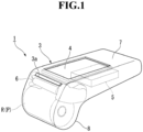
- FIG. 1 is a perspective view for illustrating a portable terminal according to at least one embodiment of the present invention.
- a portable terminal 1 is capable of performing printing on a recording sheet P.
- the recording sheet P is a heat sensitive sheet that develops a color when heat is applied thereto, and is used suitably for printing a variety of labels, receipts, and tickets.
- the recording sheet P is set in the portable terminal 1 in a state of a roll sheet R obtained by rolling the recording sheet P so as to have a hollow hole, and printing is performed on a part drawn from the roll sheet R.
- the portable terminal 1 includes a casing 3, a display unit 4, a control unit 5, and a printing unit 6.
- the casing 3 formed into a hollow box-shape is made of a metal material or plastic such as ABS or a composite material of ABS and polycarbonate.
- the casing 3 includes a main body portion 7 having a rectangular parallelepiped shape, and a roll sheet receiving portion 8 formed at one end portion of the main body portion 7 in a longitudinal direction thereof so as to be bent toward one side of a thickness direction of the main body portion 7.
- the printing unit 6 is received at the one end portion of the main body portion 7 in the longitudinal direction.
- a discharge port 3a is formed in one end surface of the main body portion 7 in the longitudinal direction. The discharge port 3a is configured to discharge the recording sheet P printed by passing through the printing unit 6.
- the display unit 4 is arranged on a main surface of the main body portion 7, which faces the other side in the thickness direction.
- the display unit 4 is, for example, a liquid crystal panel.
- the display unit 4 is connected to the control unit 5, and is configured to display various kinds of information.
- the roll sheet receiving portion 8 is configured to receive the roll sheet R.
- the printing unit 6 is a so-called thermal printer.
- FIG. 2 is a perspective view for illustrating a printing unit according to the embodiment.
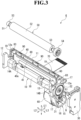
- FIG. 3 is an exploded perspective view for illustrating the printing unit according to the embodiment.
- the printing unit 6 includes a platen roller 50, a thermal head 40, a head support plate 80 (support plate), a main body frame 10 (frame), urging members 90, a motor 60, a first reduction gear 31, and a second reduction gear 32.
- the platen roller 50 conveys the recording sheet P.
- the thermal head 40 performs printing on the recording sheet P through press contact with an outer peripheral surface of the platen roller 50.
- the head support plate 80 is arranged on a side opposite to the platen roller 50 across the thermal head 40, and supports the thermal head 40.
- the main body frame 10 includes a rear plate portion 11 arranged on a side opposite to the platen roller 50 across the head support plate 80, and supports the platen roller 50 and the head support plate 80.
- the urging members 90 urge the head support plate 80.
- the motor 60 rotates the platen roller 50 about a rotation axis O.
- the first reduction gear 31 and the second reduction gear 32 reduce a driving force of the motor 60, and transmit the driving force to a driven gear 54 fixed to the platen roller 50.
- the printing unit 6 is configured to convey the recording sheet P passing between the platen roller 50 and the thermal head 40 in a direction indicated by an arrow A.
- a direction along the arrow A is defined as a vertical direction L1
- the direction indicated by the arrow A is defined as an upper side.
- a direction which is orthogonal to the vertical direction L1 and matches an axial direction of the platen roller 50 is defined as a horizontal direction L2.
- a direction orthogonal to the vertical direction L1 and the horizontal direction L2 is defined as a fore-and-aft direction L3
- the platen roller 50 side with respect to the thermal head 40 in the fore-and-aft direction L3 is defined as a front side.
- FIG. 4 is a perspective view for illustrating part of components of the printing unit according to the embodiment.
- FIG. 5 is a view for illustrating the printing unit according to the embodiment when viewed from above.
- the main body frame 10 is formed into a U-shape opened toward the front side when viewed in the vertical direction L1.
- the main body frame 10 includes a rear plate portion 11 extending in the horizontal direction L2, a first side wall portion 12 formed upright from one (left) end portion of the rear plate portion 11 in the horizontal direction L2 toward the front side, a second side wall portion 13 formed upright from another (right) end portion of the rear plate portion 11 in the horizontal direction L2 toward the front side, and a sheet guide portion 18 formed between the first side wall portion 12 and the second side wall portion 13.
- the rear plate portion 11, the first side wall portion 12, the second side wall portion 13, and the sheet guide portion 18 are integrally formed of, for example, a polycarbonate resin containing glass fibers.
- the rear plate portion 11 is formed into a plate shape having a thickness in the fore-and-aft direction L3.
- the first side wall portion 12 is formed into a plate shape having a thickness in the horizontal direction L2. A portion of an upper edge of the first side wall portion 12 is cut downward to form a first roller insertion groove 14A.
- the second side wall portion 13 is formed into a plate shape having a thickness in the horizontal direction L2. A portion of an upper edge of the second side wall portion 13 is cut downward to form a second roller insertion groove 14B.
- the first roller insertion groove 14A and the second roller insertion groove 14B are formed so as to match each other when viewed in the horizontal direction L2.
- the platen roller 50 is removably inserted into the first roller insertion groove 14A and the second roller insertion groove 14B.
- FIG. 6 is a view for illustrating the printing unit according to the embodiment when viewed from a left side thereof.
- a hole portion 12a is formed in the first side wall portion 12.
- a hole portion 13a is formed in the second side wall portion 13.
- the hole portions 12a and 13a are formed so as to match each other when viewed in the horizontal direction L2.
- the hole portions 12a and 13a are each formed into a rectangular shape having a pair of sides extending in the fore-and-aft direction L3 and the remaining pair of sides extending in the vertical direction L1 when viewed in the horizontal direction L2.
- the sheet guide portion 18 is formed into a column shape extending along the horizontal direction L2.
- a left end portion of the sheet guide portion 18 is connected to an inner surface of the first side wall portion 12.
- a right end portion of the sheet guide portion 18 is connected to an inner surface of the second side wall portion 13.
- a gearbox portion 15 is formed on an outer side of the second side wall portion 13.
- the gearbox portion 15 includes a peripheral wall portion 16 formed to extend upright from a peripheral edge of the second side wall portion 13 toward the outer side in the horizontal direction L2. That is, the gearbox portion 15 is formed of the second side wall portion 13 and the peripheral wall portion 16, and is opened toward the outer side in the horizontal direction L2.
- the peripheral wall portion 16 is opened upward when viewed in the horizontal direction L2.
- the peripheral wall portion 16 includes a pair of locking recessed portions 17 formed so as to be recessed downward.
- the pair of locking recessed portions 17 are formed on both front and rear sides of an upper opening of the peripheral wall portion 16, respectively.
- a gear cover 30 is engaged with the pair of locking recessed portions 17.
- the gear cover 30 covers an inner side of the gearbox portion 15 from an outer side thereof in the horizontal direction L2.
- the first reduction gear 31 and the second reduction gear 32 which mesh with each other are assembled inside the gearbox portion 15 so as to be rotatable.
- the motor 60 generates torque about an output axis Q.
- the motor 60 is arranged so that the output axis Q is parallel to the rotation axis O of the platen roller 50 (see FIG. 2 ).
- the motor 60 is arranged on a side opposite to the platen roller 50 across the sheet guide portion 18 and below the rear plate portion 11.
- the motor 60 is fixed to an inner surface of the second side wall portion 13 in the horizontal direction L2.
- An output shaft 61 of the motor 60 passes through the second side wall portion 13.
- the output shaft 61 meshes with the first reduction gear 31 inside the gearbox portion 15.
- a flexible printed board 70 is connected to the motor 60.
- the motor 60 is electrically connected to the control unit 5 (see FIG. 1 ) via the flexible printed board 70.
- the motor 60 is configured to be driven based on a signal from the control unit 5.
- the thermal head 40 is configured to perform printing on the recording sheet P (see FIG. 2 ).
- the thermal head 40 is arranged in front of the rear plate portion 11.
- the thermal head 40 is formed into a rectangular shape having its longitudinal direction defined as the horizontal direction L2 when viewed in the fore-and-aft direction L3.
- the thermal head 40 is arranged under a state in which a thickness direction of the thermal head 40 matches the fore-and-aft direction L3.
- a head surface 40a of the thermal head 40 faces a side opposite to the rear plate portion 11 (front side). On the head surface 40a of the thermal head 40, a large number of heating elements 41 are arrayed in the horizontal direction L2.
- the head surface 40a is opposed to a printing surface of the recording sheet P, and the recording sheet P can be nipped between the head surface 40a and the outer peripheral surface of the platen roller 50.
- the thermal head 40 is connected to the control unit 5 (see FIG. 1 ) through intermediation of the flexible printed board 70.
- a driver IC (not shown) mounted on the thermal head 40 is configured to control heat generation of the heating elements 41 based on the signal from the control unit 5. Through the control of the heat generation of the heating elements 41, the thermal head 40 prints, for example, various kinds of letters and figures on the printing surface of the recording sheet P.
- the thermal head 40 is fixed to the head support plate 80 by being bonded onto a front surface of the head support plate 80 with use of, for example, a double-sided tape.
- the head support plate 80 is arranged in front of the rear plate portion 11 and behind the sheet guide portion 18.
- the head support plate 80 is arranged between the first side wall portion 12 and the second side wall portion 13.
- the head support plate 80 is made of a metal material.
- the head support plate 80 is a plate-like member having its longitudinal direction defined as the horizontal direction L2.
- the head support plate 80 is arranged under a state in which a thickness direction of the head support plate 80 matches the fore-and-aft direction L3.
- the head support plate 80 extends in the horizontal direction L2 and the vertical direction L1 so as to have a constant thickness over an entire region of the head support plate 80 excluding protruding portions 85 to be described later.
- the thermal head 40 is fixed to the front surface of the head support plate 80.
- An intermediate position of the thermal head 40 in the horizontal direction L2 matches an intermediate position of the head support plate 80 in the horizontal direction L2.
- FIG. 7 is a plan view for illustrating the head support plate in the embodiment.
- the head support plate 80 includes a fixed portion 81 and a pair of stoppers 83.
- the fixed portion 81 is formed at a lower portion of the head support plate 80.
- the fixed portion 81 is located at a center portion of the head support plate 80 in the horizontal direction L2, and protrudes downward.
- the fixed portion 81 is sandwiched between the rear plate portion 11 and the sheet guide portion 18 of the main body frame 10, and thus displacement of the fixed portion 81 in the fore-and-aft direction L3 with respect to the main body frame 10 is substantially regulated.
- the head support plate 80 is pivotable about the fixed portion 81 so that an upper portion of the head support plate 80 is moved in the fore-and-aft direction.
- the pair of stoppers 83 are formed at an upper end portion of the head support plate 80.
- Each of the pair of stoppers 83 protrudes outward in the horizontal direction L2 so as to have a substantially constant width when viewed in the fore-and-aft direction L3.
- the stoppers 83 are inserted into the hole portions 12a and 13a of the main body frame 10, respectively.
- the stopper 83 is inserted with a gap in the fore-and-aft direction L3 with respect to an inner wall surface of a corresponding one of the hole portions 12a and 13a.
- the stoppers 83 are movable in the fore-and-aft direction L3 inside the hole portions 12a and 13a, respectively, along with pivot of the head support plate 80, and may be brought into contact with the inner wall surfaces of the hole portions 12a and 13a, respectively. Through the contact of the stoppers 83 with the inner wall surfaces of the hole portions 12a and 13a, the pivot amount of the head support plate 80 is regulated. A rear gap G (see FIG.
- the platen roller 50 is supported by the main body frame 10 so as to be rotatable about the rotation axis O.
- the platen roller 50 is arranged so as to be opposed to the thermal head 40 under a state in which the rotation axis O matches the horizontal direction L2.
- the platen roller 50 is rotated about the rotation axis O under a state in which the recording sheet P is nipped between the platen roller 50 and the thermal head 40, to thereby convey the recording sheet P in the direction indicated by the arrow A.
- the platen roller 50 includes a roller shaft 51, a roller main body 52 mounted on the roller shaft 51, and a pair of bearings 53 mounted at both ends of the roller shaft 51.
- the roller shaft 51 is formed slightly longer than the separation distance between the first side wall portion 12 and the second side wall portion 13 of the main body frame 10.
- the roller main body 52 is made of, for example, rubber, and is arranged along the horizontal direction L2 uniformly over the entire region excluding portions corresponding to both the ends of the roller shaft 51.
- the pair of bearings 53 of the platen roller 50 are inserted into the first roller insertion groove 14A and the second roller insertion groove 14B of the main body frame 10, respectively.
- the bearings 53 are held in the first roller insertion groove 14A and the second roller insertion groove 14B by locking springs 19 supported on the main body frame 10.
- the platen roller 50 is held so as to be rotatable relative to the main body frame 10.
- the locking springs 19 are elastically deformed in order to insert and remove the bearings 53 into and from the first roller insertion groove 14A and the second roller insertion groove 14B, the platen roller 50 is mountable to and removable from the main body frame 10.
- the platen roller 50 Under a state in which the platen roller 50 is inserted into the first roller insertion groove 14A and the second roller insertion groove 14B, the platen roller 50 is arranged so that an outer peripheral surface of the roller main body 52 is brought into contact with the head surface 40a of the thermal head 40 while nipping the recording sheet P drawn out from the roll sheet R (see FIG. 1 ) between the platen roller 50 and the thermal head 40.
- the driven gear 54 is fixed on another (right) end portion of the platen roller 50 in the horizontal direction L2.
- the driven gear 54 is assembled to an upper part of the gearbox portion 15 when the platen roller 50 is held on the first side wall portion 12 and the second side wall portion 13.
- the driven gear 54 meshes with the second reduction gear 32. With this, a rotational driving force from the motor 60 is transmitted to the driven gear 54 via the first reduction gear 31 and the second reduction gear 32.
- the platen roller 50 is rotated under a state of being held on the first side wall portion 12 and the second side wall portion 13, thereby being capable of conveying the recording sheet P (see FIG. 2 ).
- FIG. 8 is a view for illustrating the printing unit according to the embodiment when viewed from an upper rear side thereof.
- each of the urging members 90 is arranged between the head support plate 80 and the rear plate portion 11.
- the urging member 90 urges the head support plate 80 and the rear plate portion 11 in a direction of separating the head support plate 80 and the rear plate portion 11 away from each other.
- the urging member 90 presses the head support plate 80 to the platen roller 50 side.
- the urging member 90 is a helical compression spring that is extended and compressed in the fore-and-aft direction L3.
- the urging member 90 is a conical spring having a diameter decreasing from the front side to the rear side. A rear end portion of the urging member 90 is held in abutment against a front surface 11a of the rear plate portion 11.
- a front end portion of the urging member 90 is held in abutment against a surface (rear surface) of the head support plate 80 facing the rear plate portion 11 side.
- the urging members 90 are arranged in a bilaterally symmetric manner with respect to the intermediate position of the head support plate 80 in the horizontal direction L2. Three urging members 90 are arrayed at equal intervals in the horizontal direction L2.
- the protruding portions 85 are formed on the rear surface of the head support plate 80.
- Each of the protruding portions 85 is formed into a columnar shape, and protrudes from the head support plate 80 to the rear plate portion 11 side.
- the protruding portions 85 have the same height.
- the protruding portions 85 are arranged so as to overlap the rear plate portion 11 when viewed in a thickness direction (fore-and-aft direction) of the head support plate 80.
- a pair of the protruding portions 85 is provided for each of the urging members 90.
- the pair of the protruding portions 85 are provided apart from each other with an interval in the horizontal direction L2.
- the interval between the pair of the protruding portions 85 is smaller than a width of the front end portion of the urging member 90 in the horizontal direction L2.
- the pair of the protruding portions 85 can be brought into contact with the front end portion of the urging member 90 from the upper side.
- the pair of the protruding portions 85 are brought into contact with the front end portion of the urging member 90 so as to regulate upward movement of the urging member 90, to thereby position the urging member 90.
- each of a pair of the protruding portions 85 corresponding to the center urging member 90 is referred to as a center protruding portion 85A in some cases.
- the center urging member 90 is, among all the urging members 90, one urging member 90 other than the urging members 90 arranged at both ends in the horizontal direction L2, in other words, among all the urging members 90, the urging member 90 arranged in the middle as counted from the urging members 90 arranged at the both ends in the horizontal direction L2.
- FIG. 9 is an enlarged view for illustrating a portion IX of FIG. 5 .
- the rear plate portion 11 includes holding portions 21 and recessed portions 23.
- the holding portions 21 hold the urging members 90 therein.
- the recessed portions 23 are formed to prevent contact between the rear plate portion 11 and the protruding portions 85.
- Each holding portion 21 is opened in the front surface 11a of the rear plate portion 11 and formed into a recessed shape recessed to the rear side.
- the holding portion 21 extends in the vertical direction L1, and is opened in an upper end surface of the rear plate portion 11.
- the number of the holding portions 21 is the same as the number of the urging members 90 (three in this embodiment).
- the rear end portion of the urging member 90 is arranged in the holding portion 21.
- the holding portion 21 allows entry of the rear end portion of the urging member 90 from the upper side, and regulates displacement of the rear end portion of the urging member 90 in the horizontal direction L2.
- the recessed portions 23 are formed in portions of the rear plate portion 11 that are opposed to the protruding portions 85 of the head support plate 80 in the fore-and-aft direction L3 in a one-to-one relationship, respectively.
- the recessed portions 23 are opened in the front surface 11a of the rear plate portion 11 and recessed to the rear side.
- the recessed portions 23 are each opened continuously in a range from the front surface 11a to the upper end surface of the rear plate portion 11.
- the recessed portions 23 are formed in the rear plate portion 11 so as to include entire portions overlapping the protruding portions 85 when viewed in the fore-and-aft direction L3. With this configuration, the recessed portions 23 prevent the protruding portions 85 from being brought into contact with the rear plate portion 11 when the protruding portions 85 are displaced to the rear side.
- One recessed portion 23 is formed at each side adjacent position of the holding portion 21 in the horizontal direction L2.
- the recessed portion 23, which receives the center protruding portion 85A, has a smaller dimension in the vertical direction than a dimension of the holding portion 21, which holds the center urging member 90 therein, in the vertical direction.
- Each of the recessed portions 23 communicates with the holding portion 21.
- openings of the recessed portions 23 are continuous with an opening of the holding portion 21. Opening edges of the recessed portions 23 and an opening edge of the holding portion 21 in the upper end surface of the rear plate portion 11 are chamfered.
- the recessed portions 23 are formed so as to be shallower than the holding portion 21 to which the recessed portions 23 are adjacent.
- the recessed portions 23 each have a depth larger than a height of the protruding portion 85. As illustrated in FIG. 9 , a depth D of the recessed portion 23 is a depth determined with reference to the front surface 11a of the rear plate portion 11. A height H of the protruding portion 85 is a height determined with reference to the rear surface of the head support plate 80.
- a displacement amount at a center portion of the head support plate 80 in the horizontal direction L2 may be maximum.
- the head support plate 80 is formed into a plate-like shape having a thickness in the fore-and-aft direction L3, and hence the head support plate 80 easily bends in the fore-and-aft direction L3.
- the recessed portions 23 are formed in portions of the rear plate portion 11 of the main body frame 10 that are opposed to the protruding portions 85 of the head support plate 80 in the fore-and-aft direction L3, respectively. With this configuration, even when the head support plate 80 is displaced to the rear plate portion 11 side along the fore-and-aft direction L3, the recessed portions 23 receive the protruding portions 85, thereby being capable of preventing the protruding portions 85 from being brought into contact with the rear plate portion 11.
- the head support plate 80 bends so that the protruding portions 85 enter the recessed portions 23, under a state in which the protruding portions 85 are held in non-contact with the rear plate portion 11, the head support plate 80 is brought into contact with portions of the rear plate portion 11 outside the recessed portions 23. At this time, the head support plate 80 is brought into surface contact with flat portions in vicinities of the openings of the recessed portions 23 in the front surface 11a of the rear plate portion 11.
- the head support plate is displaced due to an impact given to the printing unit, and thus the protruding portions are brought into contact with the rear plate portion, inertia acts on the head support plate continuously even after the protruding portions are brought into contact with the rear plate portion.
- displacement of the protruding portions is regulated by the rear plate portion, and hence the head support plate may be deformed so as to bend with a larger curvature as compared to a case in which the protruding portions are not brought into contact with the rear plate portion.
- the protruding portions 85 can be prevented from being brought into contact with the rear plate portion 11, and hence even when an impact is given to the printing unit 6, the head support plate 80 can be prevented from bending with a relatively large curvature. Accordingly, excessive distortion can be prevented from occurring in the thermal head 40 supported by the head support plate 80 and causing breakage of the thermal head 40.
- the printing unit 6 having excellent impact resistance can be provided.
- the recessed portions 23 are formed in the portions opposed to the protruding portions 85 (center protruding portions 85A) that correspond to, among all the urging members 90, one urging member 90 other than the urging members 90 arranged at the both ends in the horizontal direction L2.
- the protruding portions 85 closer to the center portion of the head support plate 80 have larger displacement amounts.
- the recessed portions 23 receive, among all the protruding portions 85, the protruding portions 85 having relatively large displacement amounts.
- the protruding portions 85 can be more reliably prevented from being brought into contact with the rear plate portion 11.
- the recessed portions 23 are formed in the portions opposed to the protruding portions 85 (center protruding portions 85A) that correspond to, among all the urging members 90, the urging member 90 arranged in the middle as counted from the urging members 90 arranged at the both ends in the horizontal direction L2.
- the recessed portions 23 have depths larger than the heights of the protruding portions 85, thereby being capable of preventing the protruding portions 85 from being brought into contact with bottom surfaces of the recessed portions 23.
- the head support plate 80 bends so that the protruding portions 85 enter the recessed portions 23, under a state in which the protruding portions 85 are held in non-contact with the rear plate portion 11, the head support plate 80 is brought into contact with the portions of the rear plate portion 11 outside the recessed portions 23.
- a reaction force is applied to a wider range of the head support plate 80 when the head support plate 80 is brought into contact with the rear plate portion 11, thereby being capable of preventing an excessive external force from being applied to a relatively narrow range of the thermal head 40. Accordingly, occurrence of stress concentration on the thermal head 40 is avoided, thereby being capable of more effectively preventing breakage of the thermal head 40.
- the portable terminal 1 includes the printing unit 6 described above, and hence can be provided as a portable terminal having high durability.
- the plurality of urging members 90 are provided on the printing unit 6, and the protruding portions 85 are provided for each of the urging members 90.
- the recessed portions 23 are formed in the portions of the rear plate portion 11 opposed to the protruding portions 85, respectively.
- the present invention is not limited to this configuration.
- only one urging member may be provided.
- the recessed portions may be formed only in portions of the rear plate portion that are opposed to part of the protruding portions.
- the part of the protruding portions include a protruding portion that regulates displacement of, among all the urging members, the urging member other than the urging members arranged at the both ends in the horizontal direction.
- the recessed portion be formed in a portion opposed to the protruding portion that corresponds at least to the urging member other than the urging members arranged at the both ends.
- the part of the protruding portions include a protruding portion that regulates displacement of, among all the urging members, the urging member arranged in the middle as counted from the urging members arranged at the both ends in the horizontal direction. That is, it is further desired that the recessed portion be formed in a portion opposed to the protruding portion that corresponds at least to the center urging member.
- the recessed portion may be formed only in a portion opposed to the center protruding portion 85A.
- the protruding portions are each formed into a columnar shape, but the shape of each of the protruding portions is not particularly limited. Further, for one urging member, only one protruding portion may be provided or three or more protruding portions may be provided.
Landscapes
- Electronic Switches (AREA)
- Printers Characterized By Their Purpose (AREA)
- Handling Of Sheets (AREA)
Abstract
Description
- The present invention relates to a printing unit and a portable terminal.
- Hitherto, there has been known a printing unit that performs printing on a heat sensitive sheet (see, for example,
JP 2016-159482 A - The related-art printing unit described above includes a thermal head, a support plate, a platen roller, a frame, and an elastic member. The thermal head is fixed to the support plate. The frame supports the platen roller and the support plate. The elastic member is arranged in a gap between the support plate and the frame, and presses the support plate to the platen roller side. The elastic member applies a predetermined head pressing force between the platen roller and the thermal head.
- However, in the related-art printing unit described above, there is the gap between the support plate and the frame, and hence the support plate may bend. Thus, when an impact is given to the printing unit at the time of, for example, falling, the support plate bends and the thermal head is distorted, which may cause breakage of the thermal head.
- Accordingly, the present invention provides a printing unit having excellent impact resistance, and a portable terminal including the printing unit.
- According to one embodiment of the present invention, there is provided a printing unit includes: a platen roller, which extends in an axial direction, and is configured to convey a recording sheet; a thermal head configured to perform printing on the recording sheet through press contact with an outer peripheral surface of the platen roller; a support plate, which is arranged on a side opposite to the platen roller across the thermal head, and is configured to support the thermal head; a frame, which includes a rear plate portion arranged on a side opposite to the platen roller across the support plate, and is configured to support both ends of the support plate in the axial direction; at least one urging member, which is arranged between the rear plate portion and the support plate, and is configured to press the support plate to the platen roller side; and a protruding portion, which is formed on the support plate to protrude from the support plate to the rear plate portion side, and is configured to regulate displacement of a predetermined urging member of the at least one urging member, wherein a recessed portion is formed in a portion of the rear plate portion opposed to the protruding portion in a thickness direction of the support plate.
- In the above-mentioned thermal printer according to the one embodiment of the present invention, preferably the at least one urging member includes three or more urging members arrayed in the axial direction, and wherein the protruding portion regulates displacement of, among the at least one urging member, an urging member other than urging members arranged at both ends in the axial direction.
- In the above-mentioned thermal printer according to the one embodiment of the present invention, preferably the at least one urging member includes a plurality of and an odd number of urging members, and wherein the protruding portion regulates displacement of, among the at least one urging member, an urging member arranged in a middle as counted from the urging members arranged at the both ends in the axial direction.
- In the above-mentioned thermal printer according to the one embodiment of the present invention, preferably the recessed portion has a depth larger than a height of the protruding portion.
- In the above-mentioned thermal printer according to the one embodiment of the present invention, preferably when the support plate bends so that the protruding portion enters the recessed portion, under a state in which the protruding portion is held in non-contact with the rear plate portion, the support plate is brought into contact with a portion of the rear plate portion outside the recessed portion.
- According to one embodiment of the present invention, there is provided a portable terminal that includes the above printing unit.
-
-
FIG. 1 is a perspective view for illustrating a portable terminal according to at least one embodiment of the present invention. -
FIG. 2 is a perspective view for illustrating a printing unit according to the embodiment. -
FIG. 3 is an exploded perspective view for illustrating the printing unit according to the embodiment. -
FIG. 4 is a perspective view for illustrating part of the printing unit according to the embodiment. -
FIG. 5 is a view for illustrating the printing unit according to the embodiment when viewed from above. -
FIG. 6 is a view for illustrating the printing unit according to the embodiment when viewed from a left side thereof. -
FIG. 7 is a plan view for illustrating a head support plate in the embodiment. -
FIG. 8 is a view for illustrating the printing unit according to the embodiment when viewed from an upper rear side thereof. -
FIG. 9 is an enlarged view for illustrating a portion IX ofFIG. 5 . - Now, an embodiment of the present invention is described by way of example only with reference to the drawings. In the following description, components having the same or similar function are denoted by the same reference symbols. In some cases, overlapping description of the components is omitted.
-
FIG. 1 is a perspective view for illustrating a portable terminal according to at least one embodiment of the present invention. - As illustrated in
FIG. 1 , aportable terminal 1 is capable of performing printing on a recording sheet P. The recording sheet P is a heat sensitive sheet that develops a color when heat is applied thereto, and is used suitably for printing a variety of labels, receipts, and tickets. The recording sheet P is set in theportable terminal 1 in a state of a roll sheet R obtained by rolling the recording sheet P so as to have a hollow hole, and printing is performed on a part drawn from the roll sheet R. - The
portable terminal 1 includes acasing 3, a display unit 4, a control unit 5, and aprinting unit 6. - The
casing 3 formed into a hollow box-shape is made of a metal material or plastic such as ABS or a composite material of ABS and polycarbonate. Thecasing 3 includes amain body portion 7 having a rectangular parallelepiped shape, and a rollsheet receiving portion 8 formed at one end portion of themain body portion 7 in a longitudinal direction thereof so as to be bent toward one side of a thickness direction of themain body portion 7. Theprinting unit 6 is received at the one end portion of themain body portion 7 in the longitudinal direction. Adischarge port 3a is formed in one end surface of themain body portion 7 in the longitudinal direction. Thedischarge port 3a is configured to discharge the recording sheet P printed by passing through theprinting unit 6. The display unit 4 is arranged on a main surface of themain body portion 7, which faces the other side in the thickness direction. The display unit 4 is, for example, a liquid crystal panel. The display unit 4 is connected to the control unit 5, and is configured to display various kinds of information. The rollsheet receiving portion 8 is configured to receive the roll sheet R. Theprinting unit 6 is a so-called thermal printer. -
FIG. 2 is a perspective view for illustrating a printing unit according to the embodiment.FIG. 3 is an exploded perspective view for illustrating the printing unit according to the embodiment. - As illustrated in
FIG. 2 andFIG. 3 , theprinting unit 6 includes aplaten roller 50, athermal head 40, a head support plate 80 (support plate), a main body frame 10 (frame), urgingmembers 90, amotor 60, afirst reduction gear 31, and asecond reduction gear 32. Theplaten roller 50 conveys the recording sheet P. Thethermal head 40 performs printing on the recording sheet P through press contact with an outer peripheral surface of theplaten roller 50. Thehead support plate 80 is arranged on a side opposite to theplaten roller 50 across thethermal head 40, and supports thethermal head 40. Themain body frame 10 includes arear plate portion 11 arranged on a side opposite to theplaten roller 50 across thehead support plate 80, and supports theplaten roller 50 and thehead support plate 80. Theurging members 90 urge thehead support plate 80. Themotor 60 rotates theplaten roller 50 about a rotation axis O. Thefirst reduction gear 31 and thesecond reduction gear 32 reduce a driving force of themotor 60, and transmit the driving force to a drivengear 54 fixed to theplaten roller 50. - As illustrated in
FIG. 2 , theprinting unit 6 is configured to convey the recording sheet P passing between theplaten roller 50 and thethermal head 40 in a direction indicated by an arrow A. Mainly in the description for theprinting unit 6 below, a direction along the arrow A is defined as a vertical direction L1, and the direction indicated by the arrow A is defined as an upper side. Further, a direction which is orthogonal to the vertical direction L1 and matches an axial direction of theplaten roller 50 is defined as a horizontal direction L2. In addition, a direction orthogonal to the vertical direction L1 and the horizontal direction L2 is defined as a fore-and-aft direction L3, and theplaten roller 50 side with respect to thethermal head 40 in the fore-and-aft direction L3 is defined as a front side. -
FIG. 4 is a perspective view for illustrating part of components of the printing unit according to the embodiment.FIG. 5 is a view for illustrating the printing unit according to the embodiment when viewed from above. - As illustrated in
FIG. 3 to FIG. 5 , themain body frame 10 is formed into a U-shape opened toward the front side when viewed in the vertical direction L1. Specifically, themain body frame 10 includes arear plate portion 11 extending in the horizontal direction L2, a firstside wall portion 12 formed upright from one (left) end portion of therear plate portion 11 in the horizontal direction L2 toward the front side, a secondside wall portion 13 formed upright from another (right) end portion of therear plate portion 11 in the horizontal direction L2 toward the front side, and asheet guide portion 18 formed between the firstside wall portion 12 and the secondside wall portion 13. Therear plate portion 11, the firstside wall portion 12, the secondside wall portion 13, and thesheet guide portion 18 are integrally formed of, for example, a polycarbonate resin containing glass fibers. - The
rear plate portion 11 is formed into a plate shape having a thickness in the fore-and-aft direction L3. The firstside wall portion 12 is formed into a plate shape having a thickness in the horizontal direction L2. A portion of an upper edge of the firstside wall portion 12 is cut downward to form a firstroller insertion groove 14A. The secondside wall portion 13 is formed into a plate shape having a thickness in the horizontal direction L2. A portion of an upper edge of the secondside wall portion 13 is cut downward to form a secondroller insertion groove 14B. The firstroller insertion groove 14A and the secondroller insertion groove 14B are formed so as to match each other when viewed in the horizontal direction L2. Theplaten roller 50 is removably inserted into the firstroller insertion groove 14A and the secondroller insertion groove 14B. -
FIG. 6 is a view for illustrating the printing unit according to the embodiment when viewed from a left side thereof. - As illustrated in
FIG. 4 andFIG. 6 , ahole portion 12a is formed in the firstside wall portion 12. Ahole portion 13a is formed in the secondside wall portion 13. Thehole portions hole portions - As illustrated in
FIG. 3 andFIG. 4 , thesheet guide portion 18 is formed into a column shape extending along the horizontal direction L2. A left end portion of thesheet guide portion 18 is connected to an inner surface of the firstside wall portion 12. A right end portion of thesheet guide portion 18 is connected to an inner surface of the secondside wall portion 13. - As illustrated in
FIG. 3 , agearbox portion 15 is formed on an outer side of the secondside wall portion 13. Thegearbox portion 15 includes aperipheral wall portion 16 formed to extend upright from a peripheral edge of the secondside wall portion 13 toward the outer side in the horizontal direction L2. That is, thegearbox portion 15 is formed of the secondside wall portion 13 and theperipheral wall portion 16, and is opened toward the outer side in the horizontal direction L2. Theperipheral wall portion 16 is opened upward when viewed in the horizontal direction L2. Theperipheral wall portion 16 includes a pair of locking recessedportions 17 formed so as to be recessed downward. The pair of locking recessedportions 17 are formed on both front and rear sides of an upper opening of theperipheral wall portion 16, respectively. Agear cover 30 is engaged with the pair of locking recessedportions 17. The gear cover 30 covers an inner side of thegearbox portion 15 from an outer side thereof in the horizontal direction L2. Thefirst reduction gear 31 and thesecond reduction gear 32 which mesh with each other are assembled inside thegearbox portion 15 so as to be rotatable. - The
motor 60 generates torque about an output axis Q. Themotor 60 is arranged so that the output axis Q is parallel to the rotation axis O of the platen roller 50 (seeFIG. 2 ). Themotor 60 is arranged on a side opposite to theplaten roller 50 across thesheet guide portion 18 and below therear plate portion 11. Themotor 60 is fixed to an inner surface of the secondside wall portion 13 in the horizontal direction L2. Anoutput shaft 61 of themotor 60 passes through the secondside wall portion 13. Theoutput shaft 61 meshes with thefirst reduction gear 31 inside thegearbox portion 15. A flexible printedboard 70 is connected to themotor 60. Themotor 60 is electrically connected to the control unit 5 (seeFIG. 1 ) via the flexible printedboard 70. Themotor 60 is configured to be driven based on a signal from the control unit 5. - The
thermal head 40 is configured to perform printing on the recording sheet P (seeFIG. 2 ). Thethermal head 40 is arranged in front of therear plate portion 11. Thethermal head 40 is formed into a rectangular shape having its longitudinal direction defined as the horizontal direction L2 when viewed in the fore-and-aft direction L3. Thethermal head 40 is arranged under a state in which a thickness direction of thethermal head 40 matches the fore-and-aft direction L3. Ahead surface 40a of thethermal head 40 faces a side opposite to the rear plate portion 11 (front side). On thehead surface 40a of thethermal head 40, a large number ofheating elements 41 are arrayed in the horizontal direction L2. - The
head surface 40a is opposed to a printing surface of the recording sheet P, and the recording sheet P can be nipped between thehead surface 40a and the outer peripheral surface of theplaten roller 50. Thethermal head 40 is connected to the control unit 5 (seeFIG. 1 ) through intermediation of the flexible printedboard 70. A driver IC (not shown) mounted on thethermal head 40 is configured to control heat generation of theheating elements 41 based on the signal from the control unit 5. Through the control of the heat generation of theheating elements 41, thethermal head 40 prints, for example, various kinds of letters and figures on the printing surface of the recording sheet P. Thethermal head 40 is fixed to thehead support plate 80 by being bonded onto a front surface of thehead support plate 80 with use of, for example, a double-sided tape. - The
head support plate 80 is arranged in front of therear plate portion 11 and behind thesheet guide portion 18. Thehead support plate 80 is arranged between the firstside wall portion 12 and the secondside wall portion 13. Thehead support plate 80 is made of a metal material. Thehead support plate 80 is a plate-like member having its longitudinal direction defined as the horizontal direction L2. Thehead support plate 80 is arranged under a state in which a thickness direction of thehead support plate 80 matches the fore-and-aft direction L3. Thehead support plate 80 extends in the horizontal direction L2 and the vertical direction L1 so as to have a constant thickness over an entire region of thehead support plate 80 excluding protrudingportions 85 to be described later. Thethermal head 40 is fixed to the front surface of thehead support plate 80. An intermediate position of thethermal head 40 in the horizontal direction L2 matches an intermediate position of thehead support plate 80 in the horizontal direction L2. -
FIG. 7 is a plan view for illustrating the head support plate in the embodiment. - As illustrated in
FIG. 7 , thehead support plate 80 includes a fixedportion 81 and a pair ofstoppers 83. - The fixed
portion 81 is formed at a lower portion of thehead support plate 80. The fixedportion 81 is located at a center portion of thehead support plate 80 in the horizontal direction L2, and protrudes downward. The fixedportion 81 is sandwiched between therear plate portion 11 and thesheet guide portion 18 of themain body frame 10, and thus displacement of the fixedportion 81 in the fore-and-aft direction L3 with respect to themain body frame 10 is substantially regulated. Thehead support plate 80 is pivotable about the fixedportion 81 so that an upper portion of thehead support plate 80 is moved in the fore-and-aft direction. - As illustrated in
FIG. 3 andFIG. 7 , the pair ofstoppers 83 are formed at an upper end portion of thehead support plate 80. Each of the pair ofstoppers 83 protrudes outward in the horizontal direction L2 so as to have a substantially constant width when viewed in the fore-and-aft direction L3. Thestoppers 83 are inserted into thehole portions main body frame 10, respectively. Thestopper 83 is inserted with a gap in the fore-and-aft direction L3 with respect to an inner wall surface of a corresponding one of thehole portions stoppers 83 are movable in the fore-and-aft direction L3 inside thehole portions head support plate 80, and may be brought into contact with the inner wall surfaces of thehole portions stoppers 83 with the inner wall surfaces of thehole portions head support plate 80 is regulated. A rear gap G (seeFIG. 6 ) between thestopper 83 and the inner wall surface of thehole portion 12a or the inner wall surface of thehole portion 13a is set to have a size capable of preventing a portion of thehead support plate 80 other than the fixedportion 81 and thestoppers 83 from being brought into contact with themain body frame 10 even when thestopper 83 is advanced and brought into contact with the inner wall surface of thehole portion 12a or the inner wall surface of thehole portion 13a. - As illustrated in
FIG. 2 , theplaten roller 50 is supported by themain body frame 10 so as to be rotatable about the rotation axis O. Theplaten roller 50 is arranged so as to be opposed to thethermal head 40 under a state in which the rotation axis O matches the horizontal direction L2. Theplaten roller 50 is rotated about the rotation axis O under a state in which the recording sheet P is nipped between theplaten roller 50 and thethermal head 40, to thereby convey the recording sheet P in the direction indicated by the arrow A. - As illustrated in
FIG. 3 , theplaten roller 50 includes aroller shaft 51, a rollermain body 52 mounted on theroller shaft 51, and a pair ofbearings 53 mounted at both ends of theroller shaft 51. Theroller shaft 51 is formed slightly longer than the separation distance between the firstside wall portion 12 and the secondside wall portion 13 of themain body frame 10. The rollermain body 52 is made of, for example, rubber, and is arranged along the horizontal direction L2 uniformly over the entire region excluding portions corresponding to both the ends of theroller shaft 51. - As illustrated in
FIG. 2 andFIG. 3 , the pair ofbearings 53 of theplaten roller 50 are inserted into the firstroller insertion groove 14A and the secondroller insertion groove 14B of themain body frame 10, respectively. Thebearings 53 are held in the firstroller insertion groove 14A and the secondroller insertion groove 14B by lockingsprings 19 supported on themain body frame 10. With this configuration, theplaten roller 50 is held so as to be rotatable relative to themain body frame 10. Further, when the locking springs 19 are elastically deformed in order to insert and remove thebearings 53 into and from the firstroller insertion groove 14A and the secondroller insertion groove 14B, theplaten roller 50 is mountable to and removable from themain body frame 10. Under a state in which theplaten roller 50 is inserted into the firstroller insertion groove 14A and the secondroller insertion groove 14B, theplaten roller 50 is arranged so that an outer peripheral surface of the rollermain body 52 is brought into contact with thehead surface 40a of thethermal head 40 while nipping the recording sheet P drawn out from the roll sheet R (seeFIG. 1 ) between theplaten roller 50 and thethermal head 40. - As illustrated in
FIG. 3 , the drivengear 54 is fixed on another (right) end portion of theplaten roller 50 in the horizontal direction L2. The drivengear 54 is assembled to an upper part of thegearbox portion 15 when theplaten roller 50 is held on the firstside wall portion 12 and the secondside wall portion 13. The drivengear 54 meshes with thesecond reduction gear 32. With this, a rotational driving force from themotor 60 is transmitted to the drivengear 54 via thefirst reduction gear 31 and thesecond reduction gear 32. Theplaten roller 50 is rotated under a state of being held on the firstside wall portion 12 and the secondside wall portion 13, thereby being capable of conveying the recording sheet P (seeFIG. 2 ). -
FIG. 8 is a view for illustrating the printing unit according to the embodiment when viewed from an upper rear side thereof. - As illustrated in
FIG. 5 andFIG. 8 , each of the urgingmembers 90 is arranged between thehead support plate 80 and therear plate portion 11. The urgingmember 90 urges thehead support plate 80 and therear plate portion 11 in a direction of separating thehead support plate 80 and therear plate portion 11 away from each other. The urgingmember 90 presses thehead support plate 80 to theplaten roller 50 side. The urgingmember 90 is a helical compression spring that is extended and compressed in the fore-and-aft direction L3. Specifically, the urgingmember 90 is a conical spring having a diameter decreasing from the front side to the rear side. A rear end portion of the urgingmember 90 is held in abutment against afront surface 11a of therear plate portion 11. A front end portion of the urgingmember 90 is held in abutment against a surface (rear surface) of thehead support plate 80 facing therear plate portion 11 side. The urgingmembers 90 are arranged in a bilaterally symmetric manner with respect to the intermediate position of thehead support plate 80 in the horizontal direction L2. Three urgingmembers 90 are arrayed at equal intervals in the horizontal direction L2. - As illustrated in
FIG. 7 andFIG. 8 , the protrudingportions 85 are formed on the rear surface of thehead support plate 80. Each of the protrudingportions 85 is formed into a columnar shape, and protrudes from thehead support plate 80 to therear plate portion 11 side. The protrudingportions 85 have the same height. The protrudingportions 85 are arranged so as to overlap therear plate portion 11 when viewed in a thickness direction (fore-and-aft direction) of thehead support plate 80. A pair of the protrudingportions 85 is provided for each of the urgingmembers 90. The pair of the protrudingportions 85 are provided apart from each other with an interval in the horizontal direction L2. The interval between the pair of the protrudingportions 85 is smaller than a width of the front end portion of the urgingmember 90 in the horizontal direction L2. The pair of the protrudingportions 85 can be brought into contact with the front end portion of the urgingmember 90 from the upper side. The pair of the protrudingportions 85 are brought into contact with the front end portion of the urgingmember 90 so as to regulate upward movement of the urgingmember 90, to thereby position the urgingmember 90. In the following description, among the protrudingportions 85, each of a pair of the protrudingportions 85 corresponding to thecenter urging member 90 is referred to as acenter protruding portion 85A in some cases. Thecenter urging member 90 is, among all the urgingmembers 90, one urgingmember 90 other than the urgingmembers 90 arranged at both ends in the horizontal direction L2, in other words, among all the urgingmembers 90, the urgingmember 90 arranged in the middle as counted from the urgingmembers 90 arranged at the both ends in the horizontal direction L2. -
FIG. 9 is an enlarged view for illustrating a portion IX ofFIG. 5 . - As illustrated in
FIG. 4 ,FIG. 5 , andFIG. 9 , therear plate portion 11 includes holdingportions 21 and recessedportions 23. The holdingportions 21 hold the urgingmembers 90 therein. The recessedportions 23 are formed to prevent contact between therear plate portion 11 and the protrudingportions 85. - Each holding
portion 21 is opened in thefront surface 11a of therear plate portion 11 and formed into a recessed shape recessed to the rear side. The holdingportion 21 extends in the vertical direction L1, and is opened in an upper end surface of therear plate portion 11. The number of the holdingportions 21 is the same as the number of the urging members 90 (three in this embodiment). The rear end portion of the urgingmember 90 is arranged in the holdingportion 21. The holdingportion 21 allows entry of the rear end portion of the urgingmember 90 from the upper side, and regulates displacement of the rear end portion of the urgingmember 90 in the horizontal direction L2. - The recessed
portions 23 are formed in portions of therear plate portion 11 that are opposed to the protrudingportions 85 of thehead support plate 80 in the fore-and-aft direction L3 in a one-to-one relationship, respectively. The recessedportions 23 are opened in thefront surface 11a of therear plate portion 11 and recessed to the rear side. The recessedportions 23 are each opened continuously in a range from thefront surface 11a to the upper end surface of therear plate portion 11. The recessedportions 23 are formed in therear plate portion 11 so as to include entire portions overlapping the protrudingportions 85 when viewed in the fore-and-aft direction L3. With this configuration, the recessedportions 23 prevent the protrudingportions 85 from being brought into contact with therear plate portion 11 when the protrudingportions 85 are displaced to the rear side. - One recessed
portion 23 is formed at each side adjacent position of the holdingportion 21 in the horizontal direction L2. The recessedportion 23, which receives thecenter protruding portion 85A, has a smaller dimension in the vertical direction than a dimension of the holdingportion 21, which holds thecenter urging member 90 therein, in the vertical direction. Each of the recessedportions 23 communicates with the holdingportion 21. In the upper end surface of therear plate portion 11, openings of the recessedportions 23 are continuous with an opening of the holdingportion 21. Opening edges of the recessedportions 23 and an opening edge of the holdingportion 21 in the upper end surface of therear plate portion 11 are chamfered. The recessedportions 23 are formed so as to be shallower than the holdingportion 21 to which the recessedportions 23 are adjacent. The recessedportions 23 each have a depth larger than a height of the protrudingportion 85. As illustrated inFIG. 9 , a depth D of the recessedportion 23 is a depth determined with reference to thefront surface 11a of therear plate portion 11. A height H of the protrudingportion 85 is a height determined with reference to the rear surface of thehead support plate 80. - Operations of the above-mentioned
printing unit 6 are described. - When an impact is given to the
printing unit 6 at the time of, for example, falling, inertia acts on thehead support plate 80, and thus thehead support plate 80 is brought to be momentarily displaced with respect to themain body frame 10. Depending on an orientation of the falling, thehead support plate 80 is displaced with respect to themain body frame 10 so as to reduce the gaps between thestoppers 83 of thehead support plate 80 and the inner wall surfaces of thehole portions main body frame 10. Further, under a state in which displacement of thestoppers 83 with respect to themain body frame 10 is regulated, both ends of thehead support plate 80 in the horizontal direction L2 substantially serve as fixed ends, and thus thehead support plate 80 bends. In this case, a displacement amount at a center portion of thehead support plate 80 in the horizontal direction L2 may be maximum. In particular, thehead support plate 80 is formed into a plate-like shape having a thickness in the fore-and-aft direction L3, and hence thehead support plate 80 easily bends in the fore-and-aft direction L3. - The recessed
portions 23 are formed in portions of therear plate portion 11 of themain body frame 10 that are opposed to the protrudingportions 85 of thehead support plate 80 in the fore-and-aft direction L3, respectively. With this configuration, even when thehead support plate 80 is displaced to therear plate portion 11 side along the fore-and-aft direction L3, the recessedportions 23 receive the protrudingportions 85, thereby being capable of preventing the protrudingportions 85 from being brought into contact with therear plate portion 11. - When the
head support plate 80 bends so that the protrudingportions 85 enter the recessedportions 23, under a state in which the protrudingportions 85 are held in non-contact with therear plate portion 11, thehead support plate 80 is brought into contact with portions of therear plate portion 11 outside the recessedportions 23. At this time, thehead support plate 80 is brought into surface contact with flat portions in vicinities of the openings of the recessedportions 23 in thefront surface 11a of therear plate portion 11. - Here, if the head support plate is displaced due to an impact given to the printing unit, and thus the protruding portions are brought into contact with the rear plate portion, inertia acts on the head support plate continuously even after the protruding portions are brought into contact with the rear plate portion. In this case, displacement of the protruding portions is regulated by the rear plate portion, and hence the head support plate may be deformed so as to bend with a larger curvature as compared to a case in which the protruding portions are not brought into contact with the rear plate portion. According to this embodiment, the protruding
portions 85 can be prevented from being brought into contact with therear plate portion 11, and hence even when an impact is given to theprinting unit 6, thehead support plate 80 can be prevented from bending with a relatively large curvature. Accordingly, excessive distortion can be prevented from occurring in thethermal head 40 supported by thehead support plate 80 and causing breakage of thethermal head 40. Thus, theprinting unit 6 having excellent impact resistance can be provided. - Further, in this embodiment, the recessed
portions 23 are formed in the portions opposed to the protruding portions 85 (center protruding portions 85A) that correspond to, among all the urgingmembers 90, one urgingmember 90 other than the urgingmembers 90 arranged at the both ends in the horizontal direction L2. When thehead support plate 80 bends so that the center portion of thehead support plate 80 in the horizontal direction L2 approaches therear plate portion 11, the protrudingportions 85 closer to the center portion of thehead support plate 80 have larger displacement amounts. According to this embodiment, even when thehead support plate 80 bends so that the center portion of thehead support plate 80 in the horizontal direction L2 approaches therear plate portion 11, the recessedportions 23 receive, among all the protrudingportions 85, the protrudingportions 85 having relatively large displacement amounts. Thus, the protrudingportions 85 can be more reliably prevented from being brought into contact with therear plate portion 11. - Moreover, in this embodiment, the recessed
portions 23 are formed in the portions opposed to the protruding portions 85 (center protruding portions 85A) that correspond to, among all the urgingmembers 90, the urgingmember 90 arranged in the middle as counted from the urgingmembers 90 arranged at the both ends in the horizontal direction L2. With this configuration, even when thehead support plate 80 bends so that the center portion of thehead support plate 80 in the horizontal direction L2 approaches therear plate portion 11, the recessedportions 23 receive, among all the protrudingportions 85, the protrudingportions 85 having the largest displacement amounts. Thus, the protrudingportions 85 can be more reliably prevented from being brought into contact with therear plate portion 11. - In addition, the recessed
portions 23 have depths larger than the heights of the protrudingportions 85, thereby being capable of preventing the protrudingportions 85 from being brought into contact with bottom surfaces of the recessedportions 23. - When the
head support plate 80 bends so that the protrudingportions 85 enter the recessedportions 23, under a state in which the protrudingportions 85 are held in non-contact with therear plate portion 11, thehead support plate 80 is brought into contact with the portions of therear plate portion 11 outside the recessedportions 23. Thus, as compared to a case in which the protruding portions are brought into contact with the rear plate portion, a reaction force is applied to a wider range of thehead support plate 80 when thehead support plate 80 is brought into contact with therear plate portion 11, thereby being capable of preventing an excessive external force from being applied to a relatively narrow range of thethermal head 40. Accordingly, occurrence of stress concentration on thethermal head 40 is avoided, thereby being capable of more effectively preventing breakage of thethermal head 40. - The
portable terminal 1 according to this embodiment includes theprinting unit 6 described above, and hence can be provided as a portable terminal having high durability. - The present invention is not limited to the embodiment described above with reference to the drawings, and various modification examples may be employed within the technical scope of the present invention.
- For example, in the embodiment described above, the plurality of urging
members 90 are provided on theprinting unit 6, and the protrudingportions 85 are provided for each of the urgingmembers 90. Further, the recessedportions 23 are formed in the portions of therear plate portion 11 opposed to the protrudingportions 85, respectively. However, the present invention is not limited to this configuration. For example, only one urging member may be provided. Further, the recessed portions may be formed only in portions of the rear plate portion that are opposed to part of the protruding portions. In this case, it is desired that the part of the protruding portions include a protruding portion that regulates displacement of, among all the urging members, the urging member other than the urging members arranged at the both ends in the horizontal direction. That is, it is desired that the recessed portion be formed in a portion opposed to the protruding portion that corresponds at least to the urging member other than the urging members arranged at the both ends. In addition, when a plural number of and an odd number of urging members are provided, it is further desired that the part of the protruding portions include a protruding portion that regulates displacement of, among all the urging members, the urging member arranged in the middle as counted from the urging members arranged at the both ends in the horizontal direction. That is, it is further desired that the recessed portion be formed in a portion opposed to the protruding portion that corresponds at least to the center urging member. For example, the recessed portion may be formed only in a portion opposed to thecenter protruding portion 85A. - In the embodiment described above, the protruding portions are each formed into a columnar shape, but the shape of each of the protruding portions is not particularly limited. Further, for one urging member, only one protruding portion may be provided or three or more protruding portions may be provided.
- Besides the above, the components in the above-mentioned embodiment may be replaced by well-known components as appropriate without departing from the scope of the present invention as defined by the claims.
Claims (6)
- A printing unit (6), comprising:a platen roller (50), which extends in an axial direction, and is configured to convey a recording sheet (P);a thermal head (40) configured to perform printing on the recording sheet (P) through press contact with an outer peripheral surface of the platen roller (50);a support plate (80), which is arranged on a side opposite to the platen roller (50) across the thermal head (40), and is configured to support the thermal head (40);a frame (10), which includes a rear plate portion (11) arranged on a side opposite to the platen roller (50) across the support plate (80), and is configured to support both ends of the support plate (80) in the axial direction;at least one urging member (90), which is arranged between the rear plate portion (11) and the support plate (80), and is configured to press the support plate (80) to the platen roller (50) side; anda protruding portion (85), which is formed on the support plate (80) to protrude from the support plate (80) to the rear plate portion side, and is configured to regulate displacement of a predetermined urging member (90) of the at least one urging member (90),wherein a recessed portion (23) is formed in a portion of the rear plate portion (11) opposed to the protruding portion (85) in a thickness direction of the support plate (80).
- The printing unit (6) according to claim 1,wherein the at least one urging member (90) includes three or more urging members (90) arrayed in the axial direction, andwherein the protruding portion (85) regulates displacement of, among the at least one urging member (90), an urging member (90) other than urging members (90) arranged at both ends in the axial direction.
- The printing unit (6) according to claim 2,wherein the at least one urging member (90) includes a plurality of and an odd number of urging members (90), andwherein the protruding portion (85) regulates displacement of, among the urging members (90), an urging member (90) arranged in a middle as counted from the urging members (90) arranged at the both ends in the axial direction.
- The printing unit (6) according to claim 1, wherein the recessed portion (23) has a depth larger than a height of the protruding portion (85).
- The printing unit (6) according to claim 1, wherein when the support plate (80) bends so that the protruding portion (85) enters the recessed portion (23), under a state in which the protruding portion (85) is held in non-contact with the rear plate portion (11), the support plate (80) is brought into contact with a portion of the rear plate portion (11) outside the recessed portion (23).
- A portable terminal, comprising the printing unit (6) of claim 1.
Applications Claiming Priority (1)
| Application Number | Priority Date | Filing Date | Title |
|---|---|---|---|
| JP2022104176A JP2024004551A (en) | 2022-06-29 | 2022-06-29 | Printing unit and portable terminal |
Publications (2)
| Publication Number | Publication Date |
|---|---|
| EP4299325A1 true EP4299325A1 (en) | 2024-01-03 |
| EP4299325B1 EP4299325B1 (en) | 2025-01-01 |
Family
ID=87047839
Family Applications (1)
| Application Number | Title | Priority Date | Filing Date |
|---|---|---|---|
| EP23181391.6A Active EP4299325B1 (en) | 2022-06-29 | 2023-06-26 | Printing unit and portable terminal |
Country Status (6)
| Country | Link |
|---|---|
| US (1) | US12280607B2 (en) |
| EP (1) | EP4299325B1 (en) |
| JP (1) | JP2024004551A (en) |
| KR (1) | KR20240002707A (en) |
| CN (2) | CN117301728A (en) |
| TW (1) | TW202419300A (en) |
Citations (2)
| Publication number | Priority date | Publication date | Assignee | Title |
|---|---|---|---|---|
| JP2016159482A (en) | 2015-02-27 | 2016-09-05 | セイコーインスツル株式会社 | Printing unit and thermal printer |
| EP4005808A1 (en) * | 2020-11-30 | 2022-06-01 | Seiko Instruments Inc. | Printing unit and portable terminal |
Family Cites Families (3)
| Publication number | Priority date | Publication date | Assignee | Title |
|---|---|---|---|---|
| JP3536888B2 (en) * | 1996-11-25 | 2004-06-14 | ブラザー工業株式会社 | Thermal head type image recording device |
| JP2011168029A (en) * | 2010-02-22 | 2011-09-01 | Seiko Instruments Inc | Printer |
| JP2017205899A (en) * | 2016-05-16 | 2017-11-24 | セイコーインスツル株式会社 | Thermal printer and portable terminal |
-
2022
- 2022-06-29 JP JP2022104176A patent/JP2024004551A/en active Pending
-
2023
- 2023-06-08 TW TW112121357A patent/TW202419300A/en unknown
- 2023-06-21 US US18/338,698 patent/US12280607B2/en active Active
- 2023-06-26 EP EP23181391.6A patent/EP4299325B1/en active Active
- 2023-06-26 KR KR1020230081868A patent/KR20240002707A/en active Pending
- 2023-06-29 CN CN202310783880.3A patent/CN117301728A/en active Pending
- 2023-06-29 CN CN202321680211.5U patent/CN220349346U/en active Active
Patent Citations (2)
| Publication number | Priority date | Publication date | Assignee | Title |
|---|---|---|---|---|
| JP2016159482A (en) | 2015-02-27 | 2016-09-05 | セイコーインスツル株式会社 | Printing unit and thermal printer |
| EP4005808A1 (en) * | 2020-11-30 | 2022-06-01 | Seiko Instruments Inc. | Printing unit and portable terminal |
Also Published As
| Publication number | Publication date |
|---|---|
| KR20240002707A (en) | 2024-01-05 |
| CN117301728A (en) | 2023-12-29 |
| US12280607B2 (en) | 2025-04-22 |
| CN220349346U (en) | 2024-01-16 |
| US20240001689A1 (en) | 2024-01-04 |
| TW202419300A (en) | 2024-05-16 |
| EP4299325B1 (en) | 2025-01-01 |
| JP2024004551A (en) | 2024-01-17 |
Similar Documents
| Publication | Publication Date | Title |
|---|---|---|
| EP3061615B1 (en) | Printing unit and thermal printer | |
| US7980547B2 (en) | Sheet supplying devices and image recording apparatuses including the same | |
| US7275882B2 (en) | Image recording apparatus | |
| EP4005808B1 (en) | Printing unit and portable terminal | |
| CN1076670C (en) | Printer | |
| US9180694B2 (en) | Recording apparatus | |
| EP4299325B1 (en) | Printing unit and portable terminal | |
| EP1803670B1 (en) | Sheet-conveying device | |
| US7011303B2 (en) | Sheet feeder and image forming apparatus having the same | |
| EP4005809B1 (en) | Printing unit and portable terminal | |
| EP1772278B1 (en) | Image recording apparatus | |
| US7618139B2 (en) | Printer having improved recording medium feeding mechanism | |
| EP0721846B1 (en) | Sheet feed mechanism and printer | |
| EP4331853B1 (en) | Printing unit and portable terminal | |
| JP4725322B2 (en) | Image forming apparatus | |
| JP4882667B2 (en) | Printing device | |
| EP1004529A1 (en) | A roller feed device for a print substrate of non-uniform thickness | |
| JP2007176120A (en) | Carriage drive device and image forming apparatus | |
| JPH0197673A (en) | Serial printer |
Legal Events
| Date | Code | Title | Description |
|---|---|---|---|
| PUAI | Public reference made under article 153(3) epc to a published international application that has entered the european phase |
Free format text: ORIGINAL CODE: 0009012 |
|
| STAA | Information on the status of an ep patent application or granted ep patent |
Free format text: STATUS: THE APPLICATION HAS BEEN PUBLISHED |
|
| AK | Designated contracting states |
Kind code of ref document: A1 Designated state(s): AL AT BE BG CH CY CZ DE DK EE ES FI FR GB GR HR HU IE IS IT LI LT LU LV MC ME MK MT NL NO PL PT RO RS SE SI SK SM TR |
|
| STAA | Information on the status of an ep patent application or granted ep patent |
Free format text: STATUS: REQUEST FOR EXAMINATION WAS MADE |
|
| 17P | Request for examination filed |
Effective date: 20240606 |
|
| RBV | Designated contracting states (corrected) |
Designated state(s): AL AT BE BG CH CY CZ DE DK EE ES FI FR GB GR HR HU IE IS IT LI LT LU LV MC ME MK MT NL NO PL PT RO RS SE SI SK SM TR |
|
| GRAP | Despatch of communication of intention to grant a patent |
Free format text: ORIGINAL CODE: EPIDOSNIGR1 |
|
| STAA | Information on the status of an ep patent application or granted ep patent |
Free format text: STATUS: GRANT OF PATENT IS INTENDED |
|
| INTG | Intention to grant announced |
Effective date: 20240826 |
|
| GRAS | Grant fee paid |
Free format text: ORIGINAL CODE: EPIDOSNIGR3 |
|
| GRAA | (expected) grant |
Free format text: ORIGINAL CODE: 0009210 |
|
| STAA | Information on the status of an ep patent application or granted ep patent |
Free format text: STATUS: THE PATENT HAS BEEN GRANTED |
|
| P01 | Opt-out of the competence of the unified patent court (upc) registered |
Free format text: CASE NUMBER: APP_60058/2024 Effective date: 20241106 |
|
| AK | Designated contracting states |
Kind code of ref document: B1 Designated state(s): AL AT BE BG CH CY CZ DE DK EE ES FI FR GB GR HR HU IE IS IT LI LT LU LV MC ME MK MT NL NO PL PT RO RS SE SI SK SM TR |
|
| REG | Reference to a national code |
Ref country code: GB Ref legal event code: FG4D |
|
| REG | Reference to a national code |
Ref country code: DE Ref legal event code: R096 Ref document number: 602023001572 Country of ref document: DE |
|
| REG | Reference to a national code |
Ref country code: CH Ref legal event code: EP |
|
| REG | Reference to a national code |
Ref country code: IE Ref legal event code: FG4D |
|
| REG | Reference to a national code |
Ref country code: LT Ref legal event code: MG9D |
|
| REG | Reference to a national code |
Ref country code: NL Ref legal event code: MP Effective date: 20250101 |
|
| REG | Reference to a national code |
Ref country code: AT Ref legal event code: MK05 Ref document number: 1755858 Country of ref document: AT Kind code of ref document: T Effective date: 20250101 |
|
| PG25 | Lapsed in a contracting state [announced via postgrant information from national office to epo] |
Ref country code: NL Free format text: LAPSE BECAUSE OF FAILURE TO SUBMIT A TRANSLATION OF THE DESCRIPTION OR TO PAY THE FEE WITHIN THE PRESCRIBED TIME-LIMIT Effective date: 20250101 |
|
| PG25 | Lapsed in a contracting state [announced via postgrant information from national office to epo] |
Ref country code: FI Free format text: LAPSE BECAUSE OF FAILURE TO SUBMIT A TRANSLATION OF THE DESCRIPTION OR TO PAY THE FEE WITHIN THE PRESCRIBED TIME-LIMIT Effective date: 20250101 |
|
| PG25 | Lapsed in a contracting state [announced via postgrant information from national office to epo] |
Ref country code: PL Free format text: LAPSE BECAUSE OF FAILURE TO SUBMIT A TRANSLATION OF THE DESCRIPTION OR TO PAY THE FEE WITHIN THE PRESCRIBED TIME-LIMIT Effective date: 20250101 |
|
| PG25 | Lapsed in a contracting state [announced via postgrant information from national office to epo] |
Ref country code: ES Free format text: LAPSE BECAUSE OF FAILURE TO SUBMIT A TRANSLATION OF THE DESCRIPTION OR TO PAY THE FEE WITHIN THE PRESCRIBED TIME-LIMIT Effective date: 20250101 |
|
| PG25 | Lapsed in a contracting state [announced via postgrant information from national office to epo] |
Ref country code: IS Free format text: LAPSE BECAUSE OF FAILURE TO SUBMIT A TRANSLATION OF THE DESCRIPTION OR TO PAY THE FEE WITHIN THE PRESCRIBED TIME-LIMIT Effective date: 20250501 Ref country code: NO Free format text: LAPSE BECAUSE OF FAILURE TO SUBMIT A TRANSLATION OF THE DESCRIPTION OR TO PAY THE FEE WITHIN THE PRESCRIBED TIME-LIMIT Effective date: 20250401 |
|
| PG25 | Lapsed in a contracting state [announced via postgrant information from national office to epo] |
Ref country code: HR Free format text: LAPSE BECAUSE OF FAILURE TO SUBMIT A TRANSLATION OF THE DESCRIPTION OR TO PAY THE FEE WITHIN THE PRESCRIBED TIME-LIMIT Effective date: 20250101 |
|
| PG25 | Lapsed in a contracting state [announced via postgrant information from national office to epo] |
Ref country code: PT Free format text: LAPSE BECAUSE OF FAILURE TO SUBMIT A TRANSLATION OF THE DESCRIPTION OR TO PAY THE FEE WITHIN THE PRESCRIBED TIME-LIMIT Effective date: 20250502 Ref country code: LV Free format text: LAPSE BECAUSE OF FAILURE TO SUBMIT A TRANSLATION OF THE DESCRIPTION OR TO PAY THE FEE WITHIN THE PRESCRIBED TIME-LIMIT Effective date: 20250101 |
|
| PG25 | Lapsed in a contracting state [announced via postgrant information from national office to epo] |
Ref country code: GR Free format text: LAPSE BECAUSE OF FAILURE TO SUBMIT A TRANSLATION OF THE DESCRIPTION OR TO PAY THE FEE WITHIN THE PRESCRIBED TIME-LIMIT Effective date: 20250402 Ref country code: BG Free format text: LAPSE BECAUSE OF FAILURE TO SUBMIT A TRANSLATION OF THE DESCRIPTION OR TO PAY THE FEE WITHIN THE PRESCRIBED TIME-LIMIT Effective date: 20250101 |
|
| PG25 | Lapsed in a contracting state [announced via postgrant information from national office to epo] |
Ref country code: AT Free format text: LAPSE BECAUSE OF FAILURE TO SUBMIT A TRANSLATION OF THE DESCRIPTION OR TO PAY THE FEE WITHIN THE PRESCRIBED TIME-LIMIT Effective date: 20250101 |
|
| PG25 | Lapsed in a contracting state [announced via postgrant information from national office to epo] |
Ref country code: CZ Free format text: LAPSE BECAUSE OF FAILURE TO SUBMIT A TRANSLATION OF THE DESCRIPTION OR TO PAY THE FEE WITHIN THE PRESCRIBED TIME-LIMIT Effective date: 20250101 |
|
| PG25 | Lapsed in a contracting state [announced via postgrant information from national office to epo] |
Ref country code: SE Free format text: LAPSE BECAUSE OF FAILURE TO SUBMIT A TRANSLATION OF THE DESCRIPTION OR TO PAY THE FEE WITHIN THE PRESCRIBED TIME-LIMIT Effective date: 20250101 |
|
| REG | Reference to a national code |
Ref country code: DE Ref legal event code: R097 Ref document number: 602023001572 Country of ref document: DE |
|
| PG25 | Lapsed in a contracting state [announced via postgrant information from national office to epo] |
Ref country code: SM Free format text: LAPSE BECAUSE OF FAILURE TO SUBMIT A TRANSLATION OF THE DESCRIPTION OR TO PAY THE FEE WITHIN THE PRESCRIBED TIME-LIMIT Effective date: 20250101 |
|
| PG25 | Lapsed in a contracting state [announced via postgrant information from national office to epo] |
Ref country code: DK Free format text: LAPSE BECAUSE OF FAILURE TO SUBMIT A TRANSLATION OF THE DESCRIPTION OR TO PAY THE FEE WITHIN THE PRESCRIBED TIME-LIMIT Effective date: 20250101 |
|
| PG25 | Lapsed in a contracting state [announced via postgrant information from national office to epo] |
Ref country code: IT Free format text: LAPSE BECAUSE OF FAILURE TO SUBMIT A TRANSLATION OF THE DESCRIPTION OR TO PAY THE FEE WITHIN THE PRESCRIBED TIME-LIMIT Effective date: 20250101 |
|
| PG25 | Lapsed in a contracting state [announced via postgrant information from national office to epo] |
Ref country code: EE Free format text: LAPSE BECAUSE OF FAILURE TO SUBMIT A TRANSLATION OF THE DESCRIPTION OR TO PAY THE FEE WITHIN THE PRESCRIBED TIME-LIMIT Effective date: 20250101 |
|
| PG25 | Lapsed in a contracting state [announced via postgrant information from national office to epo] |
Ref country code: RO Free format text: LAPSE BECAUSE OF FAILURE TO SUBMIT A TRANSLATION OF THE DESCRIPTION OR TO PAY THE FEE WITHIN THE PRESCRIBED TIME-LIMIT Effective date: 20250101 |
|
| PG25 | Lapsed in a contracting state [announced via postgrant information from national office to epo] |
Ref country code: SK Free format text: LAPSE BECAUSE OF FAILURE TO SUBMIT A TRANSLATION OF THE DESCRIPTION OR TO PAY THE FEE WITHIN THE PRESCRIBED TIME-LIMIT Effective date: 20250101 |
|
| PLBE | No opposition filed within time limit |
Free format text: ORIGINAL CODE: 0009261 |
|
| STAA | Information on the status of an ep patent application or granted ep patent |
Free format text: STATUS: NO OPPOSITION FILED WITHIN TIME LIMIT |
|
| 26N | No opposition filed |
Effective date: 20251002 |
|
| PG25 | Lapsed in a contracting state [announced via postgrant information from national office to epo] |
Ref country code: MC Free format text: LAPSE BECAUSE OF FAILURE TO SUBMIT A TRANSLATION OF THE DESCRIPTION OR TO PAY THE FEE WITHIN THE PRESCRIBED TIME-LIMIT Effective date: 20250101 |
|
| PG25 | Lapsed in a contracting state [announced via postgrant information from national office to epo] |
Ref country code: LU Free format text: LAPSE BECAUSE OF NON-PAYMENT OF DUE FEES Effective date: 20250626 |
|
| REG | Reference to a national code |
Ref country code: BE Ref legal event code: MM Effective date: 20250630 |
|
| PG25 | Lapsed in a contracting state [announced via postgrant information from national office to epo] |
Ref country code: IE Free format text: LAPSE BECAUSE OF NON-PAYMENT OF DUE FEES Effective date: 20250626 |
|
| PG25 | Lapsed in a contracting state [announced via postgrant information from national office to epo] |
Ref country code: BE Free format text: LAPSE BECAUSE OF NON-PAYMENT OF DUE FEES Effective date: 20250630 |
|
| PG25 | Lapsed in a contracting state [announced via postgrant information from national office to epo] |
Ref country code: FR Free format text: LAPSE BECAUSE OF NON-PAYMENT OF DUE FEES Effective date: 20250630 |
|
| PG25 | Lapsed in a contracting state [announced via postgrant information from national office to epo] |
Ref country code: LT Free format text: LAPSE BECAUSE OF FAILURE TO SUBMIT A TRANSLATION OF THE DESCRIPTION OR TO PAY THE FEE WITHIN THE PRESCRIBED TIME-LIMIT Effective date: 20250101 |
|
| PG25 | Lapsed in a contracting state [announced via postgrant information from national office to epo] |
Ref country code: RS Free format text: LAPSE BECAUSE OF FAILURE TO SUBMIT A TRANSLATION OF THE DESCRIPTION OR TO PAY THE FEE WITHIN THE PRESCRIBED TIME-LIMIT Effective date: 20250101 |
|
| PGFP | Annual fee paid to national office [announced via postgrant information from national office to epo] |
Ref country code: DE Payment date: 20260430 Year of fee payment: 4 |
|
| PG25 | Lapsed in a contracting state [announced via postgrant information from national office to epo] |
Ref country code: CY Free format text: LAPSE BECAUSE OF FAILURE TO SUBMIT A TRANSLATION OF THE DESCRIPTION OR TO PAY THE FEE WITHIN THE PRESCRIBED TIME-LIMIT Effective date: 20250101 |