EP4299322A1 - Recording device - Google Patents
Recording device Download PDFInfo
- Publication number
- EP4299322A1 EP4299322A1 EP22759672.3A EP22759672A EP4299322A1 EP 4299322 A1 EP4299322 A1 EP 4299322A1 EP 22759672 A EP22759672 A EP 22759672A EP 4299322 A1 EP4299322 A1 EP 4299322A1
- Authority
- EP
- European Patent Office
- Prior art keywords
- liquid
- liquid discharge
- controller
- discharge head
- printing
- Prior art date
- Legal status (The legal status is an assumption and is not a legal conclusion. Google has not performed a legal analysis and makes no representation as to the accuracy of the status listed.)
- Pending
Links
Images







Classifications
-
- B—PERFORMING OPERATIONS; TRANSPORTING
- B41—PRINTING; LINING MACHINES; TYPEWRITERS; STAMPS
- B41J—TYPEWRITERS; SELECTIVE PRINTING MECHANISMS, i.e. MECHANISMS PRINTING OTHERWISE THAN FROM A FORME; CORRECTION OF TYPOGRAPHICAL ERRORS
- B41J2/00—Typewriters or selective printing mechanisms characterised by the printing or marking process for which they are designed
- B41J2/005—Typewriters or selective printing mechanisms characterised by the printing or marking process for which they are designed characterised by bringing liquid or particles selectively into contact with a printing material
- B41J2/01—Ink jet
- B41J2/135—Nozzles
- B41J2/165—Prevention or detection of nozzle clogging, e.g. cleaning, capping or moistening for nozzles
- B41J2/16517—Cleaning of print head nozzles
- B41J2/16535—Cleaning of print head nozzles using wiping constructions
-
- B—PERFORMING OPERATIONS; TRANSPORTING
- B05—SPRAYING OR ATOMISING IN GENERAL; APPLYING FLUENT MATERIALS TO SURFACES, IN GENERAL
- B05B—SPRAYING APPARATUS; ATOMISING APPARATUS; NOZZLES
- B05B12/00—Arrangements for controlling delivery; Arrangements for controlling the spray area
- B05B12/08—Arrangements for controlling delivery; Arrangements for controlling the spray area responsive to condition of liquid or other fluent material to be discharged, of ambient medium or of target ; responsive to condition of spray devices or of supply means, e.g. pipes, pumps or their drive means
- B05B12/085—Arrangements for controlling delivery; Arrangements for controlling the spray area responsive to condition of liquid or other fluent material to be discharged, of ambient medium or of target ; responsive to condition of spray devices or of supply means, e.g. pipes, pumps or their drive means responsive to flow or pressure of liquid or other fluent material to be discharged
-
- B—PERFORMING OPERATIONS; TRANSPORTING
- B05—SPRAYING OR ATOMISING IN GENERAL; APPLYING FLUENT MATERIALS TO SURFACES, IN GENERAL
- B05B—SPRAYING APPARATUS; ATOMISING APPARATUS; NOZZLES
- B05B13/00—Machines or plants for applying liquids or other fluent materials to surfaces of objects or other work by spraying, not covered by groups B05B1/00 - B05B11/00
- B05B13/002—Machines or plants for applying coating liquids or other fluent materials by inkjet
-
- B—PERFORMING OPERATIONS; TRANSPORTING
- B05—SPRAYING OR ATOMISING IN GENERAL; APPLYING FLUENT MATERIALS TO SURFACES, IN GENERAL
- B05B—SPRAYING APPARATUS; ATOMISING APPARATUS; NOZZLES
- B05B13/00—Machines or plants for applying liquids or other fluent materials to surfaces of objects or other work by spraying, not covered by groups B05B1/00 - B05B11/00
- B05B13/02—Means for supporting work; Arrangement or mounting of spray heads; Adaptation or arrangement of means for feeding work
- B05B13/04—Means for supporting work; Arrangement or mounting of spray heads; Adaptation or arrangement of means for feeding work the spray heads being moved during spraying operation
- B05B13/0431—Means for supporting work; Arrangement or mounting of spray heads; Adaptation or arrangement of means for feeding work the spray heads being moved during spraying operation with spray heads moved by robots or articulated arms, e.g. for applying liquid or other fluent material to three-dimensional [3D] surfaces
-
- B—PERFORMING OPERATIONS; TRANSPORTING
- B05—SPRAYING OR ATOMISING IN GENERAL; APPLYING FLUENT MATERIALS TO SURFACES, IN GENERAL
- B05B—SPRAYING APPARATUS; ATOMISING APPARATUS; NOZZLES
- B05B15/00—Details of spraying plant or spraying apparatus not otherwise provided for; Accessories
- B05B15/50—Arrangements for cleaning; Arrangements for preventing deposits, drying-out or blockage; Arrangements for detecting improper discharge caused by the presence of foreign matter
- B05B15/58—Arrangements for cleaning; Arrangements for preventing deposits, drying-out or blockage; Arrangements for detecting improper discharge caused by the presence of foreign matter preventing deposits, drying-out or blockage by recirculating the fluid to be sprayed from upstream of the discharge opening back to the supplying means
-
- B—PERFORMING OPERATIONS; TRANSPORTING
- B41—PRINTING; LINING MACHINES; TYPEWRITERS; STAMPS
- B41J—TYPEWRITERS; SELECTIVE PRINTING MECHANISMS, i.e. MECHANISMS PRINTING OTHERWISE THAN FROM A FORME; CORRECTION OF TYPOGRAPHICAL ERRORS
- B41J19/00—Character- or line-spacing mechanisms
- B41J19/14—Character- or line-spacing mechanisms with means for effecting line or character spacing in either direction
- B41J19/142—Character- or line-spacing mechanisms with means for effecting line or character spacing in either direction with a reciprocating print head printing in both directions across the paper width
-
- B—PERFORMING OPERATIONS; TRANSPORTING
- B41—PRINTING; LINING MACHINES; TYPEWRITERS; STAMPS
- B41J—TYPEWRITERS; SELECTIVE PRINTING MECHANISMS, i.e. MECHANISMS PRINTING OTHERWISE THAN FROM A FORME; CORRECTION OF TYPOGRAPHICAL ERRORS
- B41J2/00—Typewriters or selective printing mechanisms characterised by the printing or marking process for which they are designed
- B41J2/005—Typewriters or selective printing mechanisms characterised by the printing or marking process for which they are designed characterised by bringing liquid or particles selectively into contact with a printing material
- B41J2/01—Ink jet
- B41J2/17—Ink jet characterised by ink handling
- B41J2/18—Ink recirculation systems
-
- B—PERFORMING OPERATIONS; TRANSPORTING
- B41—PRINTING; LINING MACHINES; TYPEWRITERS; STAMPS
- B41J—TYPEWRITERS; SELECTIVE PRINTING MECHANISMS, i.e. MECHANISMS PRINTING OTHERWISE THAN FROM A FORME; CORRECTION OF TYPOGRAPHICAL ERRORS
- B41J25/00—Actions or mechanisms not otherwise provided for
- B41J25/001—Mechanisms for bodily moving print heads or carriages parallel to the paper surface
- B41J25/006—Mechanisms for bodily moving print heads or carriages parallel to the paper surface for oscillating, e.g. page-width print heads provided with counter-balancing means or shock absorbers
-
- B—PERFORMING OPERATIONS; TRANSPORTING
- B41—PRINTING; LINING MACHINES; TYPEWRITERS; STAMPS
- B41J—TYPEWRITERS; SELECTIVE PRINTING MECHANISMS, i.e. MECHANISMS PRINTING OTHERWISE THAN FROM A FORME; CORRECTION OF TYPOGRAPHICAL ERRORS
- B41J3/00—Typewriters or selective printing or marking mechanisms characterised by the purpose for which they are constructed
- B41J3/407—Typewriters or selective printing or marking mechanisms characterised by the purpose for which they are constructed for marking on special material
- B41J3/4073—Printing on three-dimensional objects not being in sheet or web form, e.g. spherical or cubic objects
-
- B—PERFORMING OPERATIONS; TRANSPORTING
- B41—PRINTING; LINING MACHINES; TYPEWRITERS; STAMPS
- B41J—TYPEWRITERS; SELECTIVE PRINTING MECHANISMS, i.e. MECHANISMS PRINTING OTHERWISE THAN FROM A FORME; CORRECTION OF TYPOGRAPHICAL ERRORS
- B41J2/00—Typewriters or selective printing mechanisms characterised by the printing or marking process for which they are designed
- B41J2/005—Typewriters or selective printing mechanisms characterised by the printing or marking process for which they are designed characterised by bringing liquid or particles selectively into contact with a printing material
- B41J2/01—Ink jet
- B41J2/135—Nozzles
- B41J2/14—Structure thereof only for on-demand ink jet heads
- B41J2002/14459—Matrix arrangement of the pressure chambers
-
- B—PERFORMING OPERATIONS; TRANSPORTING
- B41—PRINTING; LINING MACHINES; TYPEWRITERS; STAMPS
- B41J—TYPEWRITERS; SELECTIVE PRINTING MECHANISMS, i.e. MECHANISMS PRINTING OTHERWISE THAN FROM A FORME; CORRECTION OF TYPOGRAPHICAL ERRORS
- B41J2202/00—Embodiments of or processes related to ink-jet or thermal heads
- B41J2202/01—Embodiments of or processes related to ink-jet heads
- B41J2202/12—Embodiments of or processes related to ink-jet heads with ink circulating through the whole print head
Definitions
- An embodiment of the disclosure relates to a recording device.
- a known recording device includes an inkjet printer or an inkjet plotter that utilizes an inkjet recording method of recording an image and the like by discharging liquid or a liquid droplet from a head.
- an inkjet printer or an inkjet plotter that utilizes an inkjet recording method of recording an image and the like by discharging liquid or a liquid droplet from a head.
- Patent Document 1 JP 2016-159514 A
- a recording device in an aspect of an embodiment, includes a liquid discharger rotatable around a predetermined rotation axis and configured to discharge liquid while circulating the liquid internally and a controller configured to control the liquid discharger to discharge a liquid droplet while reciprocating along a printing direction.
- the controller controls a position and a posture of the liquid discharger, and thus printing is started from a positive pressure side of the liquid circulating inside the liquid discharger.
- the following embodiment describes, as an example of the recording device disclosed by the present application, a liquid discharge system in which a liquid discharge head that discharges liquid (or a liquid droplet) by using an inkjet method is mounted on a robotic arm.
- the recording device disclosed by the present application can be applied to inkjet printers and inkjet plotters that utilize an inkjet recording method as well as various devices that discharge liquid (or liquid droplet) by using an inkjet method.
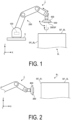
- FIGs. 1 and 2 are schematic views illustrating an outline of the liquid discharge system according to an embodiment.
- a liquid discharge system 1 includes a control unit 100, a robotic arm 200, a liquid discharge head 300, and a circulation device 400.
- the control unit 100 is built in, for example, the robotic arm 200.
- the control unit 100 may be mounted on an external device independent from the robotic arm 200, and may be communicably connected to the robotic arm 200.
- the control unit 100 outputs a command for controlling an operation of the robotic arm 200 to the robotic arm 200. This causes the control unit 100 to control, via the robotic arm 200, a position and a posture of the liquid discharge head 300 (and the circulation device 400) mounted to the most distal end portion of the robotic arm 200.
- the control unit 100 can cause the robotic arm 200 to move the liquid discharge head 300 (and the circulation device 400). This allows the control unit 100 to change the position of the liquid discharge head 300 (and the circulation device 400).
- the control unit 100 can also cause the robotic arm 200 to rotate the liquid discharge head 300 (and the circulation device 400) around a predetermined rotation axis (for example, a Y axis or a Z axis). This allows the control unit 100 to change the posture such as an orientation and an angle of the liquid discharge head 300 (and the circulation device 400).
- the robotic arm 200 operates to change the position, the posture, and the like of the liquid discharge head 300 in accordance with a command from the control unit 100.
- the robotic arm 200 is assembled on a base 5 mounted on, for example, a horizontal floor surface indoors or outdoors.
- the robotic arm 200 may be movable on the base 5.
- the robotic arm 200 is composed of a plurality of parts assembled extendably and rotatably.
- the robotic arm 200 has a degree of freedom that enables change of movement, posture, and the like necessary for the liquid discharge head 300 and is not limited to the particular configuration illustrated in FIGs. 1 and 2 .
- the liquid discharge head 300 is a so-called circulating inkjet head that discharges liquid while circulating the liquid inside the liquid discharge head.
- the liquid discharge head 300 functions as a liquid discharger that discharges liquid to a substantially horizontal working surface SF 1 _B 1 of an object B 1 to be printed (recorded) or a substantially vertical working surface SF 2 _B 1 of the object B 1 .
- the liquid discharge head 300 is mounted to the most distal end portion of the robotic arm 200 together with the circulation device 400.
- the circulation device 400 controls a circulation pressure of liquid circulating between the circulation device 400 and the liquid discharge head 300 to supply the liquid to the liquid discharge head 300.
- the circulation device 400 is mounted to the most distal end portion of the robotic arm 200 together with the liquid discharge head 300.
- the circulation device 400 changes its position and posture integrally with the liquid discharge head 300.
- the circulation pressure of the liquid to be supplied to the liquid discharge head 300 is affected by a change in the position and the posture of the liquid discharge head 300 made by the robotic arm 200.
- a discharge amount of the liquid is large, the influence on the circulation pressure increases, and discharge omission may occur.
- the present application proposes the liquid discharge system 1 capable of suppressing the occurrence of discharge omission and maintaining a quality of an image to be recorded.
- FIG. 3 is a perspective view schematically illustrating an outer appearance configuration of a liquid discharge head according to an embodiment.
- FIG. 4 is a plan view of the liquid discharge head according to an embodiment.
- FIG. 5 is a diagram schematically illustrating a channel inside the liquid discharge head according to an embodiment.
- the liquid discharge head 300 includes a housing including a member 310 having a box shape and a member 320 having a flat plate shape.
- the housing of the liquid discharge head 300 includes a first channel RT 1 for supplying liquid from the circulation device 400 to the inside of the head and a second channel RT 2 for delivering liquid recovered inside the head back to the circulation device 400.
- the member 320 of the liquid discharge head 300 has a supply port P in through which liquid is supplied to the inside of the head through the first channel RT 1 and a discharge port P out through which liquid is discharged from the inside of the head through the second channel RT 2 .
- the liquid discharge head 300 includes a supply reservoir 301, a supply manifold 302, a recovery manifold 303, a recovery reservoir 304, and an element 305.
- the supply reservoir 301 has an elongated shape extending in a longitudinal direction (Y-axis direction) of the liquid discharge head 300 and is connected to the supply manifold 302.
- the supply reservoir 301 has a channel therein. As illustrated in FIG. 4 or 5 , the liquid supplied to the supply reservoir 301 through the first channel RT 1 and the supply port P in and stored in the channel of the supply reservoir 301 is delivered to the supply manifold 302.
- the supply manifold 302 has an elongated shape extending in a lateral direction (X-axis direction) of the liquid discharge head 300 to near the recovery reservoir 304.
- the supply manifold 302 internally has a channel that communicates with the channel included in the supply reservoir 301 and with the element 305. As illustrated in FIG. 4 or 5 , the liquid delivered from the supply reservoir 301 to the supply manifold 302 is delivered from the supply manifold 302 to the element 305.
- the recovery manifold 303 has an elongated shape extending in the lateral direction (X-axis direction) of the liquid discharge head 300 to near the supply reservoir 301.
- the recovery manifold 303 internally has a channel that communicates with the channel included in the recovery reservoir 304 and with the element 305. As illustrated in FIG. 4 or 5 , liquid is not discharged from the element 305 (discharge hole 305h) to the outside is delivered to the recovery manifold 303.
- the recovery reservoir 304 has an elongated shape extending in the longitudinal direction (Y-axis direction) of the liquid discharge head 300 and is connected to the recovery manifold 303.
- the recovery reservoir 304 has a channel therein. As illustrated in FIG. 4 or 5 , the liquid delivered from the recovery manifold 303 to the recovery reservoir 304 and stored in the channel of the recovery reservoir 304 is delivered back to the circulation device 400 through the discharge port P out and the second channel RT 2 .
- the element 305 has a discharge hole 305h.
- the element 305 suctions liquid from the supply manifold 302 by using negative pressure generated in a pressure chamber (not illustrated) and discharges the suctioned liquid from the discharge hole 305h toward the object B 1 by using positive pressure generated in the pressure chamber (not illustrated).
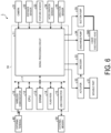
- FIG. 6 is a diagram illustrating a schematic hardware configuration example of a liquid discharge system according to an embodiment.
- FIG. 6 schematically illustrates an example of a hardware configuration of a liquid droplet discharge system, and there is no need to be limited to the particular example illustrated in FIG. 6 .
- arrows indicate flows of data or signals
- solid lines indicate physical connection relationships.
- the liquid discharge system 1 includes various sensors.
- the liquid discharge system 1 specifically includes a camera 21, a distance sensor 22, a posture sensor 23, an acceleration sensor 24, and a direction sensor 25.
- the camera 21 has a function of capturing an image of the object B 1 (working surface SF 1 _B 1 or working surface SF 2 _B 1 ) to be printed (recorded).
- the camera 21 is mounted to any position of the robotic arm 200.
- the liquid discharge system 1 may include a plurality of the cameras 21 installed at different positions.
- the camera 21 outputs the captured image to the control unit 100.
- the camera 21 may be a wide-angle camera. In this case, the control unit 100 extracts an extraction point from the image above the liquid discharge system 1 captured by the wide-angle camera.
- the control unit 100 can also generate, by using the extracted feature point as a virtual viewpoint, a bird's-eye view image of a recording (printing) status of the object B 1 (working surface SF 1 _B 1 or working surface SF 2 _B 1 ). This allows the control unit 100 to determine the recording (printing) status.
- the distance sensor 22 detects a distance between the object B 1 (working surface SF 1 _B 1 or working surface SF 2 _B 1 ) to be recorded (printed) and the liquid discharge head 300.
- the distance sensor 22 can be implemented by, for example, a time of flight (ToF) sensor or a depth sensor (also referred to as a depth camera) that acquires a depth map, a depth image, or the like.
- the distance sensor 22 is provided at any position of the circulation device 400 at which the distance between the object B 1 (working surface SF 1 _B 1 or working surface SF 2 _B 1 ) to be recorded (printed) and the liquid discharge head 300 can be detected.
- the distance sensor 22 outputs a detection result to the control unit 100.
- the control unit 100 can execute, in accordance with the distance detected by the distance sensor 22, an operation depending to a relative positional relationship between the object B 1 (working surface SF 1 _B 1 or working surface SF 2 _B 1 ) and the liquid discharge head 300.
- the posture sensor 23 detects a posture of the liquid discharge head 300.
- the posture sensor 23 can be implemented by using, for example, a three-axis or nine-axis gyro sensor.
- the posture sensor 23 detects the posture, for example, roll, pitch, and yaw of the liquid discharge head 300.
- the posture sensor 23 is provided at any position of the circulation device 400. That is, in the liquid discharge system 1, the posture of the circulation device 400 is detected as the posture of the liquid discharge head 300.
- the posture sensor 23 outputs a detection result to the control unit 100.
- the control unit 100 can specify the posture of the liquid discharge head 300 in accordance with the posture detected by the posture sensor 23.
- the acceleration sensor 24 detects an acceleration to be applied to the liquid discharge head 300.
- the acceleration sensor 24 is mounted to any position of the circulation device 400. That is, in the liquid discharge system 1, the acceleration applied to the circulation device 400 is detected as the acceleration applied to the liquid discharge head 300.
- the acceleration sensor 24 outputs a detection result to the control unit 100.
- the control unit 100 can calculate, for example, a current position of the liquid discharge head 300 with respect to a position at the start of printing in accordance with the detection result of the acceleration sensor 24 and a detection result of the direction sensor 25 described below.
- the direction sensor 25 detects a direction (orientation) in which the liquid discharge head 300 faces.
- the direction sensor 25 can be implemented by, for example, a geomagnetic sensor.
- the direction sensor 25 is mounted to any position of the circulation device 400. That is, in the liquid discharge system 1, the orientation of the circulation device 400 is detected as the orientation of the liquid discharge head 300.
- the direction sensor 25 outputs a detection result to the control unit 100.
- the control unit 100 can calculate a current orientation of the liquid discharge head 300 with respect to the orientation at the start of printing in accordance with the detection result of the direction sensor 25.
- the posture sensor 23, the acceleration sensor 24, and the direction sensor 25 described above may be implemented by an inertial measurement unit (IMU).
- the liquid discharge system 1 may include other sensors such as an ultrasonic sensor, a temperature sensor and a human detection sensor other than those illustrated in FIG. 6 .
- the liquid discharge system 1 includes a drive mechanism for driving the robotic arm 200.
- the drive mechanism includes, for example, a movable part 31 including a link (bone part) or a joint (articulation part) constituting the robotic arm 200 and an end effector, an actuator 32 for driving the movable part 31, and an encoder 33 that detects a rotation angle (position) of a motor.
- the drive mechanism appropriately controls the position, posture, and the like of the liquid discharge head 300 by achieving an operation in cooperation with the above-described various sensors and the like.
- the end effector of the movable part 31 is connected to the liquid discharge head 300 and the circulation device 400.
- the encoder 33 that can be used is an encoder using any detection method, such as an optical encoder or a magnetic encoder.
- the link constituting the robotic arm 200 may be a serial link or a parallel link.
- the liquid discharge system 1 includes a discharge pump 34, a suction pump 35, and the liquid discharge head 300.
- the discharge pump 34 feeds the liquid stored in a tank (not illustrated) to the liquid discharge head 300 through the first channel RT 1 and the supply port P in .
- the discharge pump 34 generates positive pressure for delivering the liquid stored in the tank to the liquid discharge head 300.
- the discharge pump 34 can deliver the liquid stored in the tank to the liquid discharge head 300, for example, at a predetermined constant supply pressure.
- the suction pump 35 feeds to the tank the liquid recovered in the head without being discharged from the liquid discharge head 300, through the discharge port P out and the second channel RT 2 .
- the suction pump 35 generates negative pressure for suctioning the liquid recovered in the head and feeding the same back to the tank.
- the suction pump 35 can deliver the liquid suctioned from the liquid discharge head 300 to the tank 201, for example, at a predetermined constant recovery pressure.
- the discharge pump 34 and the suction pump 35 can be implemented by a rotary pump such as a gear pump or a displacement pump such as a diaphragm pump.
- the liquid discharge system 1 includes a controller 10 that collectively controls operations of the system.
- the controller 10 has a configuration in which a signal processing circuit 11, a central processing unit (CPU) 12, a dynamic random access memory (DRAM) 13, a flash read only memory (ROM) 14, a universal serial bus (USB) connector 15, and a wireless communicator 16 are mutually connected via an internal bus 17.
- the liquid discharge system 1 includes various interfaces for inputting and outputting data to and from the camera 21, the actuator 42, the discharge pump 34, and the suction pump 35.
- the liquid discharge system 1 may include a battery or the like that supplies power to each unit included in the liquid discharge system 1.
- the various sensors described above, the actuator 32, the encoder 33, the discharge pump 34, and the suction pump 35 are connected to the signal processing circuit 11.
- the signal processing circuit 11 sequentially takes in sensor data and pump data supplied from the various sensors described above, a control signal received from an external terminal 40, and the like, and sequentially stores these data at predetermined positions in the DRAM 13 via the internal bus 17.
- the sensor data, the pump data and the like stored in the DRAM 13 are used when the CPU 12 controls an operation of the liquid discharge system 1.
- the data is transmitted to an external device such as a server via the wireless communicator 16, as necessary.
- the wireless communicator 16 has a communication function for communicating with an external device, the external terminal 40, or the like via a predetermined network such as a wireless local area network (LAN) such as Bluetooth (registered trademark) or WiFi (registered trademark) or a mobile communication network.
- LAN wireless local area network
- WiFi registered trademark
- the CPU 12 when the liquid discharge system 1 is powered on, the CPU 12 reads out a control program stored in an external memory 50 connected to the USB connector 15, and stores the read control program in the DRAM 13.
- the CPU 12 reads out control data (print control data and posture control data) stored in the flash ROM 14, and stores the read control data in the DRAM 13.
- the CPU 12 controls an operation of the liquid discharge system 1 in accordance with each sensor data, pump data, control data and the like sequentially stored in the DRAM 13 by the signal processing circuit 11, as described above.
- the CPU 12 specifies a position, a posture, and the like of the liquid discharge head 300 in accordance with each sensor data and control data sequentially stored in the DRAM 13.
- a control command to be given to the actuator 42 is generated based on a result of specifying the position, the posture, and the like of the liquid discharge head 300.
- the CPU 12 outputs the generated control command to the actuator 42 via the signal processing circuit 11.
- the CPU 12 generates a control command to be given to the discharge pump 34 and the suction pump 35 in accordance with the control data sequentially stored in the DRAM 13.
- the CPU 12 outputs the generated control command to the discharge pump 34 and the suction pump 35 via the signal processing circuit 11.
- the liquid discharge system 1 collectively controls the operation of the system by cooperation between hardware such as a CPU 12 and a predetermined program such as a control program.
- FIG. 7 is a block diagram illustrating an example of a functional configuration of each unit provided in a liquid discharge system according to an embodiment.
- FIG. 7 illustrates, in functional blocks, an example of a functional configuration of each unit provided in the liquid discharge system 1 and that there is no need to be limited to the particular example illustrated in FIG. 7 , provided that the various functions of the liquid discharge system 1 according to an embodiment can be achieved.
- FIG. 7 illustrates a function of each unit provided in the liquid discharge system 1 according to an embodiment and omits an illustration of other general components.
- the constitutional elements of each unit included in the liquid discharge system 1 illustrated in FIG. 7 are functional concepts and are not limited to the example illustrated in FIG.
- a thin solid line indicates a flow of data or a signal
- a thick solid line indicates a physical connection relationship
- control unit 100 included in the liquid discharge system 1 includes an input/output interface (IF) 110, a storage 120, and a controller 130.
- IF input/output interface
- the input/output IF 110 is various interfaces for inputting and outputting various data to and from the robotic arm 200 and the circulation device 400.
- the storage 120 includes, for example, a semiconductor memory element such as the DRAM 13 and the flash ROM 14 illustrated in FIG. 6 , and a storage device such as a hard disk and an optical disc.
- the storage 120 can store, for example, programs, data, and the like for implementing various processing executed by the controller 130.
- the programs stored in the storage 120 include a control program for implementing a processing function corresponding to each unit of the controller 130.
- the programs stored in the storage 120 include an operating system (OS) and various application programs.
- OS operating system
- the storage 120 includes a print control data storage 121 and a head control data storage 122.
- the print control data storage 121 stores print control data for controlling printing (recording) of the object B 1 .
- the print control data includes information about a size, a shape, and the like of the object B 1 , print property configuration information, print start position and print end position information, and target value information about pressures of the discharge pump 34 and the suction pump 35.
- the head control data storage 122 stores head control data for controlling the position and posture of the liquid discharge head 300.
- the head control data includes configuration information regarding the posture of the liquid discharge head 300 with respect to the object B 1 (working surface SF 1 _B 1 or working surface SF 2 _B 1 ).
- FIG. 8 is a chart illustrating an outline of head control data according to an embodiment.
- the head control data includes an item of "head movement posture” and an item of "head orientation”, which are associated with each other.
- a movement posture of the liquid discharge head 300 when printing (recording) is performed on the object B 1 (working surface SF 1 _B 1 or working surface SF 2 _B 1 ) is set.
- a positional relationship between the supply port P in and the discharge port P out for determining an orientation of the liquid discharge head 300 with respect to each of an outward path and a homeward path of the liquid discharge head 300 reciprocating along the printing direction is set.
- the positive pressure side is a supply side on which the liquid is supplied to the liquid discharge head 300, and may also be referred as an upstream side of the liquid circulating inside the liquid discharge head 300.
- the relative positional relationship among the printing direction, the supply port P in and the discharge port P out illustrated in FIG. 8 is determined according to the internal structure of the liquid discharge head 300 and the circulation direction of the liquid, and when the internal structure of the liquid discharge head 300 and the circulation direction of the liquid are different, the relative positional relationship among the printing direction, the supply port P in and the discharge port P out illustrated in FIG. 8 is naturally changed.
- the information for determining the orientation of the head is set for each of the outward path and the homeward path, but only the orientation of the head corresponding to the outward path may be set, and the orientation may be set to be reversed by 180 degrees on the homeward path.
- the controller 130 is implemented by the controller 10 (such as the signal processing circuit 11, the CPU 12, and the DRAM 13) illustrated in FIG. 5 .
- Various processing executed by the controller 130 is implemented by, for example, executing instructions described in a control program read from an internal memory such as the DRAM 13 by a processor such as the CPU 12 by using the internal memory as a work area.
- Programs that are read from the internal memory by the processor such as the CPU 12 include an OS and an application program.
- the controller 130 may be implemented by, for example, an integrated circuit such as an ASIC (application specific integrated circuit) or a FPGA (field programmable gate array).
- FIG. 9 is a diagram illustrating an outline (part 1) of operation control of the liquid discharge head according to an embodiment.
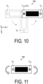
- FIG. 10 is a diagram illustrating a method (part 1) of reversing the liquid discharge head according to an embodiment.
- FIG. 11 is a diagram illustrating a method (part 2) of reversing the liquid discharge head according to an embodiment.
- FIG. 9 illustrates a schematic diagram 9-1 illustrating an operation of the liquid discharge head 300 during printing and an enlarged plan view 9-2 of the liquid discharge head 300.
- the liquid discharge head 300 appears to perform printing at intervals, but this is for clearly illustrating an operation of the liquid discharge head 300.
- the position and posture of the liquid discharge head 300 may be controlled so that printing is performed on a printing area without any gap, or the position and posture of the liquid discharge head 300 may be controlled so that printing is performed on the printing area while causing printing portions to overlap partially.
- the controller 130 controls, via the robotic arm 200, the liquid discharge head 300 to discharge the liquid while reciprocating along the printing direction PD.
- the controller 130 controls the operation of the robotic arm 200 and the position and posture of the liquid discharge head 300 so that printing is started from the positive pressure side of the liquid circulating inside the liquid discharge head 300. That is, the controller 130 adjusts the orientation of the liquid discharge head 300 so that printing on the object B 1 (working surface SF 1 _B 1 or working surface SF 2 _B 1 ) is always started from a side on which the elements 305 on the supply reservoir 301 side having a high pressure are arranged.
- the controller 130 refers to the head control data, and controls the orientation of the liquid discharge head 300 so that the supply port P in is "left” and the discharge port P out is "right” with respect to the direction (X-axis direction) orthogonal to the printing direction PD from the start of printing to the completion of printing on the outward path OW when the movement posture of the liquid discharge head 300 is substantially horizontal (substantially horizontal with respect to the XY plane).
- the controller 130 when controlling the orientation of the liquid discharge head 300, the controller 130 adjusts the arrangement direction of the elements 305 to be parallel to the direction (X-axis direction) orthogonal to the printing direction PD.
- the controller 130 refers to the head control data, and reverses the orientation of the liquid discharge head 300 so that the supply port P in is "right” and the discharge port P out is "left” with respect to the direction (X-axis direction) orthogonal to the printing direction PD from the start of printing to the completion of printing on the homeward path HW that is a next line to be printed.
- the controller 130 reverses the orientation of the liquid discharge head 300 by moving the liquid discharge head by 180 degrees in an arc-like manner around a predetermined rotation axis so that a gap does not occur on a line to be printed between the outward path OW and the homeward path HW. For example, as illustrated in FIG.
- the controller 130 can move the liquid discharge head 300 counterclockwise in an arc-like manner by 180 degrees with the discharge port P out as the rotation axis AX r . At this time, the orientation of the liquid discharge head 300 is reversed so that a gap does not occur on the line to be printed between the outward path OW and the homeward path HW.
- the controller 180 may reverse the orientation of the liquid discharge head 300 by reversing the liquid discharge head by 180 degrees on the spot without changing the position of the liquid discharge head 300. In this case, the controller 130 reverses the orientation of the liquid discharge head 300 and then moves the liquid discharge head 300 to a print start position of a next line to be printed.
- the controller 130 reverses, after the printing on the outward path OW is completed, the orientation of the liquid discharge head 300 on a maintenance area MA where the liquid discharge head 300 is retracted until the printing on the homeward path is started.
- the controller 130 adjusts, when controlling the orientation of the liquid discharge head 300, the arrangement direction of the elements 305 to be parallel to the direction (X-axis direction) orthogonal to the printing direction PD.
- the controller 130 refers to, when printing (printing of one line) on the homeward path HW is completed, the head control data, and reverses the orientation of the liquid discharge head 300 so that the supply port P in is "left” and the discharge port P out is "right” with respect to the direction (X-axis direction) orthogonal to the printing direction PD from the start of printing to the completion of printing on the outward path OW that is a next line to be printed.
- the controller 130 can reverse the orientation of the liquid discharge head 300 by moving the liquid discharge head 300 clockwise in an arc-like manner by 180 degrees with the supply port P in as the rotation axis AX r .
- the controller 130 may reverse the orientation of the liquid discharge head 300 by reversing the liquid discharge head by 180 degrees on the spot without changing the position of the liquid discharge head 300.
- the controller 130 repeatedly reverses the orientation of the liquid discharge head 300 each time printing of one line (on the outward path or homeward path) is completed until printing of all lines is completed on the working surface SF 1 _B 1 of the object B 1 .
- the controller 130 controls the orientation of the liquid discharge head 300 such that printing is always started from the positive pressure side (side where the pressure is high) of the liquid circulating inside the liquid discharge head 300 when the liquid discharge head 300 performs printing while reciprocating in a substantially horizontal movement posture with respect to the working surface SF 1 _B 1 of the object B 1 .
- the controller 130 can suppress an occurrence of discharge omission during printing in the substantially horizontal movement posture and maintain a quality of the image to be recorded.
- FIG. 12 is a diagram illustrating an outline (part 2) of the operation control of the liquid discharge head according to an embodiment.
- FIG. 12 illustrates a schematic diagram 12-1 illustrating an operation of the liquid discharge head 300 during printing and an enlarged plan view 12-2 of the liquid discharge head 300.
- the controller 130 controls the position and posture of the liquid discharge head 300 so that printing is started from the positive pressure side of the liquid circulating inside the liquid discharge head 300, as in the example illustrated in FIG. 9 .
- the controller 130 refers to the head control data, and controls the orientation of the liquid discharge head 300 so that the supply port P in is “upper” and the discharge port P out is “lower” with respect to the direction (Z-axis direction) orthogonal to the printing direction PD from the start of printing to the completion of printing on the outward path OW by the liquid discharge head 300 when the movement posture of the liquid discharge head 300 is substantially vertical (substantially horizontal with respect to the YZ plane).
- the controller 130 adjusts, when controlling the orientation of the liquid discharge head 300, the arrangement direction of the elements 305 to be parallel to the direction (Z-axis direction) orthogonal to the printing direction PD.
- the controller 130 refers to the head control data, and reverses the orientation of the liquid discharge head 300 so that the supply port P in is "lower” and the discharge port P out is "upper” with respect to the direction (Z-axis direction) orthogonal to the printing direction PD from the start of printing to the completion of printing on the return homeward path HW.
- the reversing method is the same as in the example illustrated in FIGs. 10 and 11 .
- the controller 130 reverses, after the printing on the outward path OW is completed, the orientation of the liquid discharge head 300 on the maintenance area MA where the liquid discharge head 300 is retracted until the printing on the homeward path is started.
- the controller 130 adjusts, when controlling the orientation of the liquid discharge head 300, the arrangement direction of the elements 305 to be parallel to the direction (X-axis direction) orthogonal to the printing direction PD.
- the controller 130 repeatedly reverses the orientation of the liquid discharge head 300 each time printing of one line (on the outward path or homeward path) is completed until printing of all lines is completed on the working surface SF 2 _B 1 of the object B 1 .
- the controller 130 controls the orientation of the liquid discharge head 300 so that printing is always started from the positive pressure side (side where the pressure is high) of the liquid circulating inside the liquid discharge head 300 when the liquid discharge head 300 performs printing while reciprocating in a substantially vertical movement posture with respect to the working surface SF 2 _B 1 of the object B 1 .
- the controller 130 can suppress the occurrence of discharge omission during printing in the substantially vertical movement posture and maintain the quality of an image to be recorded.
- the circulation device 400 included in the liquid discharge system 1 includes a sensor 410.
- the sensor 410 can be implemented by the distance sensor 22, the posture sensor 23, the acceleration sensor 24, and the direction sensor 25 illustrated in FIG. 6 .
- the sensor 410 outputs a detection result to the control unit 100.
- the detection result by the sensor 410 includes a distance between the object B 1 (working surface SF 1 _B 1 or working surface SF 2 _B 1 ) to be recorded (printed) and the liquid discharge head 300, a posture of the liquid discharge head 300, an acceleration applied to the liquid discharge head 300, and a direction (orientation) in which the liquid discharge head 300 faces.
- the circulation device 400 includes the discharge pump 34 and the suction pump 35 illustrated in FIG. 3 .
- the circulation device 400 supplies liquid to the liquid discharge head 300 while controlling a circulation pressure of the liquid circulating between the circulation device and the liquid discharge head 300. Liquid is supplied to the liquid discharge head 300.
- FIG. 13 is a flowchart illustrating an example of a processing procedure executed by the control unit according to an embodiment.
- the processing procedure illustrated in FIG. 13 is achieved by the controller 130 included in the control unit 100.
- the controller 130 reads the print control data and head control data from the storage 120 (step S101).
- the controller 130 specifies a positional relationship with the object B 1 that is an object to be printed in accordance with the detection result (distance information) of the sensor 410 acquired from the circulation device 400 (step S102).
- the controller 130 positions the liquid discharge head 300 at a predetermined print start position in accordance with the print control data and the positional relationship specified in step S102 (step S103).
- the controller 130 specifies the position and posture of the liquid discharge head 300 in accordance with the detection result (posture and direction) of the sensor 410 acquired from the circulation device 400 (step S104).
- the controller 130 adjusts the orientation of the liquid discharge head 300 so that the positive pressure side (side where the pressure is high) of the liquid circulating inside the head becomes the print start side (step S105).
- step S106 After adjusting the orientation of the liquid discharge head 300, the controller 130 executes and controls a printing operation (step S106).
- the controller 130 determines whether printing of one line is completed (step S107).
- step S107 When determining that the printing of one line (on the outward path or homeward path) is not completed (step S107; No), the controller 130 returns to the processing procedure of step S106 described above and continues the control of the printing operation.
- step S107 when determining that the printing of one line (on the outward path or homeward path) is completed (step S107; Yes), the controller 130 determines whether printing of all lines is completed (step S108).
- step S108 When determining that the printing of all lines is completed (step S108; Yes), the controller 130 causes the liquid discharge head 300 to retract to a predetermined retraction position (step S109), and ends the processing procedure illustrated in FIG. 13 .
- step S108 when determining that the printing of all lines is not completed (step S108; No), the controller 130 reverses the orientation of the liquid discharge head 300 (step S110), returns to the processing procedure of step S106 described above, and executes and controls the printing operation.
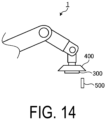
- FIG. 14 is a schematic diagram illustrating a schematic configuration of a liquid discharge system according to a variation.
- the liquid discharge system 1 includes a wiper blade 500.
- the control unit 100 controls the wiper blade 500 to wipe the liquid discharge surface.
- the liquid discharge system 1 may execute the refresh processing by a method other than wiping.
- the control unit 100 may perform spitting (flushing) when reversing the orientation of the liquid discharge head 300.
- the orientation of the liquid discharge head 300 may be reversed while the control unit 100 causes the liquid discharge head 300 to be subjected to meniscus vibration.
- Each refresh processing described above may be executed in the maintenance area MA described above.
- FIG. 15 is a flowchart illustrating an example of a processing procedure executed by the control unit according to the variation.
- the processing procedure illustrated in FIG. 15 is achieved by the controller 130 included in the control unit 100.
- the processing procedure executed by the control unit 100 according to the variation is different from the processing procedure (refer to FIG. 13 ) executed by the control unit 100 according to the embodiment described above, in that a processing procedure of step S208 illustrated in FIG. 15 is included.
- FIG. 13 a processing procedure of step S208 illustrated in FIG. 15
- step S207 when determining that printing of one line (on the outward path or homeward path) is completed (step S207; Yes), the controller 130 executes refresh processing of the discharge surface of the liquid discharge head 300 (step S208).
- the controller 130 determines whether printing of all lines is completed (step S209), and executes subsequent processing.
- the controller 130 When the controller 130 causes the liquid discharge head 300 to be subjected to meniscus vibration as the refresh processing, the controller may execute the refresh processing after the processing procedure of step S209.
- the liquid discharge system 1 disclosed by the present application can perform printing while maintaining various postures according to the object to be printed, in addition to performing printing while maintaining a substantially horizontal posture with respect to the substantially horizontal working surface SF_B 1 and performing printing while maintaining a substantially vertical posture with respect to the substantially vertical working surface SF_B 2 as in the embodiment described above.
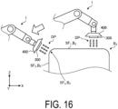
- FIG. 16 is a view illustrating an outline of a liquid discharge system according to the variation.
- the controller 130 of the control unit 100 can discharge the liquid DP and perform printing not only on the substantially horizontal working surface SF 1 _B 2 and the substantially vertical working surface SF 2 _B 2 of the object B2 as the object to be printed but also on a working surface SF 3 _B 2 as a curved surface while flexibly changing the position and posture of the liquid discharge head 300. Also in this case, the controller 130 controls the position and posture of the liquid discharge head 300 so that printing is started from the positive pressure side (side where the pressure is high) of the liquid circulating inside the liquid discharge head 300.
- the example in which the liquid discharge system 1 includes the robotic arm and the control unit 100 controls the position and posture of the liquid discharge head 300 mounted to the most distal end portion of the robotic arm 200 through the robotic arm 200 has been described.
- the control of the liquid discharge system 1 according to the embodiment and the variation described above can be applied to inkjet printers and inkjet plotters that each utilize an inkjet recording method as well as various devices that each discharge liquid (or liquid droplet) by using an inkjet method.
- various devices such as an inkjet printer utilizing the inkjet recording method may include a mechanism for reversing the orientation of the liquid discharge head 30 each time printing of one line is completed.
- control unit 100 may reverse the circulation direction of the liquid flowing through the liquid discharge head 30 each time printing of one line is completed. Specifically, after the printing on the outward path OW is completed, the control unit 100 may control the circulation pressure to change the positive pressure to the negative pressure. Thereby, printing is started from the positive pressure side (side where the pressure is high) of the liquid circulating inside the liquid discharge head 300.
Landscapes
- Engineering & Computer Science (AREA)
- Manufacturing & Machinery (AREA)
- Robotics (AREA)
- Ink Jet (AREA)
Abstract
Description
- An embodiment of the disclosure relates to a recording device.
- A known recording device includes an inkjet printer or an inkjet plotter that utilizes an inkjet recording method of recording an image and the like by discharging liquid or a liquid droplet from a head. Regarding the above-described inkjet recording device utilizing an inkjet method, a technology to have stable discharge performance has been proposed.
- Patent Document 1:
JP 2016-159514 A - In an aspect of an embodiment, a recording device includes a liquid discharger rotatable around a predetermined rotation axis and configured to discharge liquid while circulating the liquid internally and a controller configured to control the liquid discharger to discharge a liquid droplet while reciprocating along a printing direction. The controller controls a position and a posture of the liquid discharger, and thus printing is started from a positive pressure side of the liquid circulating inside the liquid discharger.
-
-
FIG. 1 is a schematic diagram illustrating an outline of a liquid discharge system according to an embodiment. -
FIG. 2 is a schematic diagram illustrating an outline of the liquid discharge system according to an embodiment. -
FIG. 3 is a perspective view schematically illustrating an outer appearance configuration of a liquid discharge head according to an embodiment. -
FIG. 4 is a plan view illustrating a liquid discharge head according to an embodiment. -
FIG. 5 is a diagram schematically illustrating a channel inside a liquid discharge head according to an embodiment. -
FIG. 6 is a diagram illustrating an outline hardware configuration example of a liquid discharge system according to an embodiment. -
FIG. 7 is a block diagram illustrating an example of a functional configuration of each unit provided in a liquid discharge system according to an embodiment. -
FIG. 8 is a chart illustrating an outline of head control data according to an embodiment. -
FIG. 9 is a diagram illustrating an outline (part 1) of operation control of a liquid discharge head according to an embodiment. -
FIG. 10 is a diagram illustrating a method (part 1) of reversing a liquid discharge head according to an embodiment. -
FIG. 11 is a diagram illustrating a method (part 2) of reversing a liquid discharge head according to an embodiment. -
FIG. 12 is a diagram illustrating an outline (part 2) of operation control of a liquid discharge head according to an embodiment. -
FIG. 13 is a flowchart illustrating an example of a processing procedure executed by a control unit according to an embodiment. -
FIG. 14 is a schematic diagram illustrating an outline configuration of a liquid discharge system according to a variation. -
FIG. 15 is a flowchart illustrating an example of a processing procedure executed by a control unit according to a variation. -
FIG. 16 is a view illustrating an outline of a liquid discharge system according to a variation. - An embodiment of a recording device disclosed by the present application will be described in detail below with reference to the accompanying drawings. The invention according to the present application is not limited by embodiments described below.
- The following embodiment describes, as an example of the recording device disclosed by the present application, a liquid discharge system in which a liquid discharge head that discharges liquid (or a liquid droplet) by using an inkjet method is mounted on a robotic arm. The recording device disclosed by the present application can be applied to inkjet printers and inkjet plotters that utilize an inkjet recording method as well as various devices that discharge liquid (or liquid droplet) by using an inkjet method.
- An outline of a liquid discharge system according to an embodiment will be described using
FIGs. 1 and 2. FIGs. 1 and 2 are schematic views illustrating an outline of the liquid discharge system according to an embodiment. - As illustrated in
FIG. 1 or 2 , aliquid discharge system 1 includes acontrol unit 100, arobotic arm 200, aliquid discharge head 300, and acirculation device 400. - The
control unit 100 is built in, for example, therobotic arm 200. Thecontrol unit 100 may be mounted on an external device independent from therobotic arm 200, and may be communicably connected to therobotic arm 200. Thecontrol unit 100 outputs a command for controlling an operation of therobotic arm 200 to therobotic arm 200. This causes thecontrol unit 100 to control, via therobotic arm 200, a position and a posture of the liquid discharge head 300 (and the circulation device 400) mounted to the most distal end portion of therobotic arm 200. - The
control unit 100 can cause therobotic arm 200 to move the liquid discharge head 300 (and the circulation device 400). This allows thecontrol unit 100 to change the position of the liquid discharge head 300 (and the circulation device 400). Thecontrol unit 100 can also cause therobotic arm 200 to rotate the liquid discharge head 300 (and the circulation device 400) around a predetermined rotation axis (for example, a Y axis or a Z axis). This allows thecontrol unit 100 to change the posture such as an orientation and an angle of the liquid discharge head 300 (and the circulation device 400). - The
robotic arm 200 operates to change the position, the posture, and the like of theliquid discharge head 300 in accordance with a command from thecontrol unit 100. Therobotic arm 200 is assembled on abase 5 mounted on, for example, a horizontal floor surface indoors or outdoors. Therobotic arm 200 may be movable on thebase 5. Therobotic arm 200 is composed of a plurality of parts assembled extendably and rotatably. Therobotic arm 200 has a degree of freedom that enables change of movement, posture, and the like necessary for theliquid discharge head 300 and is not limited to the particular configuration illustrated inFIGs. 1 and 2 . - The
liquid discharge head 300 is a so-called circulating inkjet head that discharges liquid while circulating the liquid inside the liquid discharge head. Theliquid discharge head 300 functions as a liquid discharger that discharges liquid to a substantially horizontal working surface SF1_B1 of an object B1 to be printed (recorded) or a substantially vertical working surface SF2_B1 of the object B1. Theliquid discharge head 300 is mounted to the most distal end portion of therobotic arm 200 together with thecirculation device 400. - The
circulation device 400 controls a circulation pressure of liquid circulating between thecirculation device 400 and theliquid discharge head 300 to supply the liquid to theliquid discharge head 300. Thecirculation device 400 is mounted to the most distal end portion of therobotic arm 200 together with theliquid discharge head 300. Thecirculation device 400 changes its position and posture integrally with theliquid discharge head 300. - The circulation pressure of the liquid to be supplied to the
liquid discharge head 300 is affected by a change in the position and the posture of theliquid discharge head 300 made by therobotic arm 200. When, in particular, a discharge amount of the liquid is large, the influence on the circulation pressure increases, and discharge omission may occur. In view of such problems, the present application proposes theliquid discharge system 1 capable of suppressing the occurrence of discharge omission and maintaining a quality of an image to be recorded. - The
liquid discharge head 300 according to an embodiment will be described withFIGs. 3 to 5 .FIG. 3 is a perspective view schematically illustrating an outer appearance configuration of a liquid discharge head according to an embodiment.FIG. 4 is a plan view of the liquid discharge head according to an embodiment.FIG. 5 is a diagram schematically illustrating a channel inside the liquid discharge head according to an embodiment. - As illustrated in
FIG. 3 , theliquid discharge head 300 includes a housing including amember 310 having a box shape and amember 320 having a flat plate shape. The housing of theliquid discharge head 300 includes a first channel RT1 for supplying liquid from thecirculation device 400 to the inside of the head and a second channel RT2 for delivering liquid recovered inside the head back to thecirculation device 400. As illustrated inFIG. 4 or5 , themember 320 of theliquid discharge head 300 has a supply port Pin through which liquid is supplied to the inside of the head through the first channel RT1 and a discharge port Pout through which liquid is discharged from the inside of the head through the second channel RT2. - As illustrated in
FIG. 3 , theliquid discharge head 300 includes asupply reservoir 301, asupply manifold 302, arecovery manifold 303, arecovery reservoir 304, and anelement 305. - The
supply reservoir 301 has an elongated shape extending in a longitudinal direction (Y-axis direction) of theliquid discharge head 300 and is connected to thesupply manifold 302. Thesupply reservoir 301 has a channel therein. As illustrated inFIG. 4 or5 , the liquid supplied to thesupply reservoir 301 through the first channel RT1 and the supply port Pin and stored in the channel of thesupply reservoir 301 is delivered to thesupply manifold 302. - The
supply manifold 302 has an elongated shape extending in a lateral direction (X-axis direction) of theliquid discharge head 300 to near therecovery reservoir 304. Thesupply manifold 302 internally has a channel that communicates with the channel included in thesupply reservoir 301 and with theelement 305. As illustrated inFIG. 4 or5 , the liquid delivered from thesupply reservoir 301 to thesupply manifold 302 is delivered from thesupply manifold 302 to theelement 305. - The
recovery manifold 303 has an elongated shape extending in the lateral direction (X-axis direction) of theliquid discharge head 300 to near thesupply reservoir 301. Therecovery manifold 303 internally has a channel that communicates with the channel included in therecovery reservoir 304 and with theelement 305. As illustrated inFIG. 4 or5 , liquid is not discharged from the element 305 (discharge hole 305h) to the outside is delivered to therecovery manifold 303. - The
recovery reservoir 304 has an elongated shape extending in the longitudinal direction (Y-axis direction) of theliquid discharge head 300 and is connected to therecovery manifold 303. Therecovery reservoir 304 has a channel therein. As illustrated inFIG. 4 or5 , the liquid delivered from therecovery manifold 303 to therecovery reservoir 304 and stored in the channel of therecovery reservoir 304 is delivered back to thecirculation device 400 through the discharge port Pout and the second channel RT2. - The
element 305 has adischarge hole 305h. Theelement 305, for example, suctions liquid from thesupply manifold 302 by using negative pressure generated in a pressure chamber (not illustrated) and discharges the suctioned liquid from thedischarge hole 305h toward the object B1 by using positive pressure generated in the pressure chamber (not illustrated). - Hardware Configuration Example of Liquid Discharge System A schematic configuration of the liquid discharge system according to an embodiment will be described.
FIG. 6 is a diagram illustrating a schematic hardware configuration example of a liquid discharge system according to an embodiment.FIG. 6 schematically illustrates an example of a hardware configuration of a liquid droplet discharge system, and there is no need to be limited to the particular example illustrated inFIG. 6 . In the example illustrated inFIG. 6 , arrows indicate flows of data or signals, and solid lines indicate physical connection relationships. - As illustrated in
FIG. 6 , theliquid discharge system 1 includes various sensors. Theliquid discharge system 1 specifically includes acamera 21, adistance sensor 22, aposture sensor 23, an acceleration sensor 24, and adirection sensor 25. - The
camera 21 has a function of capturing an image of the object B1 (working surface SF1_B1 or working surface SF2_B1) to be printed (recorded). Thecamera 21 is mounted to any position of therobotic arm 200. Theliquid discharge system 1 may include a plurality of thecameras 21 installed at different positions. Thecamera 21 outputs the captured image to thecontrol unit 100. Thecamera 21 may be a wide-angle camera. In this case, thecontrol unit 100 extracts an extraction point from the image above theliquid discharge system 1 captured by the wide-angle camera. Thecontrol unit 100 can also generate, by using the extracted feature point as a virtual viewpoint, a bird's-eye view image of a recording (printing) status of the object B1 (working surface SF1_B1 or working surface SF2_B1). This allows thecontrol unit 100 to determine the recording (printing) status. - The
distance sensor 22 detects a distance between the object B1 (working surface SF1_B1 or working surface SF2_B1) to be recorded (printed) and theliquid discharge head 300. Thedistance sensor 22 can be implemented by, for example, a time of flight (ToF) sensor or a depth sensor (also referred to as a depth camera) that acquires a depth map, a depth image, or the like. Thedistance sensor 22 is provided at any position of thecirculation device 400 at which the distance between the object B1 (working surface SF1_B1 or working surface SF2_B1) to be recorded (printed) and theliquid discharge head 300 can be detected. Thedistance sensor 22 outputs a detection result to thecontrol unit 100. Thecontrol unit 100 can execute, in accordance with the distance detected by thedistance sensor 22, an operation depending to a relative positional relationship between the object B1 (working surface SF1_B1 or working surface SF2_B1) and theliquid discharge head 300. - The
posture sensor 23 detects a posture of theliquid discharge head 300. Theposture sensor 23 can be implemented by using, for example, a three-axis or nine-axis gyro sensor. Theposture sensor 23 detects the posture, for example, roll, pitch, and yaw of theliquid discharge head 300. Theposture sensor 23 is provided at any position of thecirculation device 400. That is, in theliquid discharge system 1, the posture of thecirculation device 400 is detected as the posture of theliquid discharge head 300. Theposture sensor 23 outputs a detection result to thecontrol unit 100. Thecontrol unit 100 can specify the posture of theliquid discharge head 300 in accordance with the posture detected by theposture sensor 23. - The acceleration sensor 24 detects an acceleration to be applied to the
liquid discharge head 300. The acceleration sensor 24 is mounted to any position of thecirculation device 400. That is, in theliquid discharge system 1, the acceleration applied to thecirculation device 400 is detected as the acceleration applied to theliquid discharge head 300. The acceleration sensor 24 outputs a detection result to thecontrol unit 100. Thecontrol unit 100 can calculate, for example, a current position of theliquid discharge head 300 with respect to a position at the start of printing in accordance with the detection result of the acceleration sensor 24 and a detection result of thedirection sensor 25 described below. - The
direction sensor 25 detects a direction (orientation) in which theliquid discharge head 300 faces. Thedirection sensor 25 can be implemented by, for example, a geomagnetic sensor. Thedirection sensor 25 is mounted to any position of thecirculation device 400. That is, in theliquid discharge system 1, the orientation of thecirculation device 400 is detected as the orientation of theliquid discharge head 300. Thedirection sensor 25 outputs a detection result to thecontrol unit 100. Thecontrol unit 100 can calculate a current orientation of theliquid discharge head 300 with respect to the orientation at the start of printing in accordance with the detection result of thedirection sensor 25. - The
posture sensor 23, the acceleration sensor 24, and thedirection sensor 25 described above may be implemented by an inertial measurement unit (IMU). Theliquid discharge system 1 may include other sensors such as an ultrasonic sensor, a temperature sensor and a human detection sensor other than those illustrated inFIG. 6 . - The
liquid discharge system 1 includes a drive mechanism for driving therobotic arm 200. The drive mechanism includes, for example, amovable part 31 including a link (bone part) or a joint (articulation part) constituting therobotic arm 200 and an end effector, an actuator 32 for driving themovable part 31, and an encoder 33 that detects a rotation angle (position) of a motor. The drive mechanism appropriately controls the position, posture, and the like of theliquid discharge head 300 by achieving an operation in cooperation with the above-described various sensors and the like. The end effector of themovable part 31 is connected to theliquid discharge head 300 and thecirculation device 400. The encoder 33 that can be used is an encoder using any detection method, such as an optical encoder or a magnetic encoder. The link constituting therobotic arm 200 may be a serial link or a parallel link. - The
liquid discharge system 1 includes a discharge pump 34, asuction pump 35, and theliquid discharge head 300. - The discharge pump 34 feeds the liquid stored in a tank (not illustrated) to the
liquid discharge head 300 through the first channel RT1 and the supply port Pin. The discharge pump 34 generates positive pressure for delivering the liquid stored in the tank to theliquid discharge head 300. The discharge pump 34 can deliver the liquid stored in the tank to theliquid discharge head 300, for example, at a predetermined constant supply pressure. - The
suction pump 35 feeds to the tank the liquid recovered in the head without being discharged from theliquid discharge head 300, through the discharge port Pout and the second channel RT2. Thesuction pump 35 generates negative pressure for suctioning the liquid recovered in the head and feeding the same back to the tank. Thesuction pump 35 can deliver the liquid suctioned from theliquid discharge head 300 to the tank 201, for example, at a predetermined constant recovery pressure. - The discharge pump 34 and the
suction pump 35 can be implemented by a rotary pump such as a gear pump or a displacement pump such as a diaphragm pump. - The
liquid discharge system 1 includes acontroller 10 that collectively controls operations of the system. Thecontroller 10 has a configuration in which asignal processing circuit 11, a central processing unit (CPU) 12, a dynamic random access memory (DRAM) 13, a flash read only memory (ROM) 14, a universal serial bus (USB)connector 15, and a wireless communicator 16 are mutually connected via aninternal bus 17. Although not illustrated inFIG. 2 , theliquid discharge system 1 includes various interfaces for inputting and outputting data to and from thecamera 21, the actuator 42, the discharge pump 34, and thesuction pump 35. Theliquid discharge system 1 may include a battery or the like that supplies power to each unit included in theliquid discharge system 1. - The various sensors described above, the actuator 32, the encoder 33, the discharge pump 34, and the
suction pump 35 are connected to thesignal processing circuit 11. Thesignal processing circuit 11 sequentially takes in sensor data and pump data supplied from the various sensors described above, a control signal received from an external terminal 40, and the like, and sequentially stores these data at predetermined positions in theDRAM 13 via theinternal bus 17. - The sensor data, the pump data and the like stored in the
DRAM 13 are used when theCPU 12 controls an operation of theliquid discharge system 1. The data is transmitted to an external device such as a server via the wireless communicator 16, as necessary. The wireless communicator 16 has a communication function for communicating with an external device, the external terminal 40, or the like via a predetermined network such as a wireless local area network (LAN) such as Bluetooth (registered trademark) or WiFi (registered trademark) or a mobile communication network. - For example, when the
liquid discharge system 1 is powered on, theCPU 12 reads out a control program stored in anexternal memory 50 connected to theUSB connector 15, and stores the read control program in theDRAM 13. TheCPU 12 reads out control data (print control data and posture control data) stored in the flash ROM 14, and stores the read control data in theDRAM 13. - The
CPU 12 controls an operation of theliquid discharge system 1 in accordance with each sensor data, pump data, control data and the like sequentially stored in theDRAM 13 by thesignal processing circuit 11, as described above. For example, theCPU 12 specifies a position, a posture, and the like of theliquid discharge head 300 in accordance with each sensor data and control data sequentially stored in theDRAM 13. A control command to be given to the actuator 42 is generated based on a result of specifying the position, the posture, and the like of theliquid discharge head 300. TheCPU 12 outputs the generated control command to the actuator 42 via thesignal processing circuit 11. TheCPU 12 generates a control command to be given to the discharge pump 34 and thesuction pump 35 in accordance with the control data sequentially stored in theDRAM 13. TheCPU 12 outputs the generated control command to the discharge pump 34 and thesuction pump 35 via thesignal processing circuit 11. - In this way, the
liquid discharge system 1 collectively controls the operation of the system by cooperation between hardware such as aCPU 12 and a predetermined program such as a control program. - An example of a functional configuration of each unit included in the
liquid discharge system 1 according to an embodiment will be described.FIG. 7 is a block diagram illustrating an example of a functional configuration of each unit provided in a liquid discharge system according to an embodiment.FIG. 7 illustrates, in functional blocks, an example of a functional configuration of each unit provided in theliquid discharge system 1 and that there is no need to be limited to the particular example illustrated inFIG. 7 , provided that the various functions of theliquid discharge system 1 according to an embodiment can be achieved. In addition,FIG. 7 illustrates a function of each unit provided in theliquid discharge system 1 according to an embodiment and omits an illustration of other general components. The constitutional elements of each unit included in theliquid discharge system 1 illustrated inFIG. 7 are functional concepts and are not limited to the example illustrated inFIG. 7 , and are not necessarily physically configured as illustrated. For example, the specific form of distribution and integration of each of the functional blocks is not limited to that illustrated, and all or a portion thereof can be functionally or physically distributed and integrated in any unit, depending on various loads, usage conditions, and the like. In the example illustrated inFIG. 7 , a thin solid line indicates a flow of data or a signal, and a thick solid line indicates a physical connection relationship. - As illustrated in
FIG. 7 , thecontrol unit 100 included in theliquid discharge system 1 includes an input/output interface (IF) 110, astorage 120, and acontroller 130. - The input/output IF 110 is various interfaces for inputting and outputting various data to and from the
robotic arm 200 and thecirculation device 400. - The
storage 120 includes, for example, a semiconductor memory element such as theDRAM 13 and the flash ROM 14 illustrated inFIG. 6 , and a storage device such as a hard disk and an optical disc. Thestorage 120 can store, for example, programs, data, and the like for implementing various processing executed by thecontroller 130. The programs stored in thestorage 120 include a control program for implementing a processing function corresponding to each unit of thecontroller 130. The programs stored in thestorage 120 include an operating system (OS) and various application programs. - As illustrated in
FIG. 7 , thestorage 120 includes a printcontrol data storage 121 and a headcontrol data storage 122. - The print
control data storage 121 stores print control data for controlling printing (recording) of the object B1. The print control data includes information about a size, a shape, and the like of the object B1, print property configuration information, print start position and print end position information, and target value information about pressures of the discharge pump 34 and thesuction pump 35. - The head
control data storage 122 stores head control data for controlling the position and posture of theliquid discharge head 300. The head control data includes configuration information regarding the posture of theliquid discharge head 300 with respect to the object B1 (working surface SF1_B1 or working surface SF2_B1).FIG. 8 is a chart illustrating an outline of head control data according to an embodiment. - As illustrated in
FIG. 8 , the head control data includes an item of "head movement posture" and an item of "head orientation", which are associated with each other. In the item of "head movement posture", a movement posture of theliquid discharge head 300 when printing (recording) is performed on the object B1 (working surface SF1_B1 or working surface SF2_B1) is set. In the item of "head orientation", a positional relationship between the supply port Pin and the discharge port Pout for determining an orientation of theliquid discharge head 300 with respect to each of an outward path and a homeward path of theliquid discharge head 300 reciprocating along the printing direction is set. - In the example illustrated in
FIG. 8 , when the movement posture is "substantially horizontal" and the movement is performed on the "outward path", a relative positional relationship in which the supply port Pin is "left" and the discharge port P out is "right" with respect to a direction orthogonal to the printing direction (head movement direction) is set as information for determining the orientation of theliquid discharge head 300. On the other hand, when the movement posture is "substantially horizontal" and the movement is performed on the "homeward path", a relative positional relationship in which the supply port Pin is "right" and the discharge port Pout is "left" with respect to the direction orthogonal to the printing direction (head movement direction) is set as the information for determining the orientation of theliquid discharge head 300. Thereby, when the movement posture of theliquid discharge head 300 is substantially horizontal, printing is always started from a positive pressure side (a side where the pressure is high) of the liquid circulating inside theliquid discharge head 300. Here, the positive pressure side is a supply side on which the liquid is supplied to theliquid discharge head 300, and may also be referred as an upstream side of the liquid circulating inside theliquid discharge head 300. The relative positional relationship among the printing direction, the supply port Pin and the discharge port Pout illustrated inFIG. 8 is determined according to the internal structure of theliquid discharge head 300 and the circulation direction of the liquid, and when the internal structure of theliquid discharge head 300 and the circulation direction of the liquid are different, the relative positional relationship among the printing direction, the supply port Pin and the discharge port Pout illustrated inFIG. 8 is naturally changed. - In the example illustrated in
FIG. 8 , when the movement posture is "substantially vertical" and the movement is performed on the "outward path", a relative positional relationship in which the supply port Pin is "upper" and the discharge port Pout is "lower" with respect to the direction orthogonal to the printing direction (head movement direction) is set as the information for determining the orientation of theliquid discharge head 300. On the other hand, when the movement posture is "substantially vertical" and the movement is performed on the "homeward path", a relative positional relationship in which the supply port Pin is "lower" and the discharge port Pout is "upper" with respect to the direction orthogonal to the printing direction (head movement direction) is set as the information for determining the orientation of theliquid discharge head 300. Thereby, even when the moving direction of theliquid discharge head 300 is substantially vertical, printing is always started from the positive pressure side (supply side) of the liquid circulating inside theliquid discharge head 300. In the example illustrated inFIG. 7 , the information for determining the orientation of the head is set for each of the outward path and the homeward path, but only the orientation of the head corresponding to the outward path may be set, and the orientation may be set to be reversed by 180 degrees on the homeward path. - The
controller 130 is implemented by the controller 10 (such as thesignal processing circuit 11, theCPU 12, and the DRAM 13) illustrated inFIG. 5 . Various processing executed by thecontroller 130 is implemented by, for example, executing instructions described in a control program read from an internal memory such as theDRAM 13 by a processor such as theCPU 12 by using the internal memory as a work area. Programs that are read from the internal memory by the processor such as theCPU 12 include an OS and an application program. Thecontroller 130 may be implemented by, for example, an integrated circuit such as an ASIC (application specific integrated circuit) or a FPGA (field programmable gate array). - Hereinafter, a specific example of operation control by the
controller 130 will be described.FIG. 9 is a diagram illustrating an outline (part 1) of operation control of the liquid discharge head according to an embodiment.FIG. 10 is a diagram illustrating a method (part 1) of reversing the liquid discharge head according to an embodiment.FIG. 11 is a diagram illustrating a method (part 2) of reversing the liquid discharge head according to an embodiment.FIG. 9 illustrates a schematic diagram 9-1 illustrating an operation of theliquid discharge head 300 during printing and an enlarged plan view 9-2 of theliquid discharge head 300. In the example illustrated inFIG. 9 , theliquid discharge head 300 appears to perform printing at intervals, but this is for clearly illustrating an operation of theliquid discharge head 300. That is, depending on the printing method, the position and posture of theliquid discharge head 300 may be controlled so that printing is performed on a printing area without any gap, or the position and posture of theliquid discharge head 300 may be controlled so that printing is performed on the printing area while causing printing portions to overlap partially. - The
controller 130 controls, via therobotic arm 200, theliquid discharge head 300 to discharge the liquid while reciprocating along the printing direction PD. Thecontroller 130 controls the operation of therobotic arm 200 and the position and posture of theliquid discharge head 300 so that printing is started from the positive pressure side of the liquid circulating inside theliquid discharge head 300. That is, thecontroller 130 adjusts the orientation of theliquid discharge head 300 so that printing on the object B1 (working surface SF1_B1 or working surface SF2_B1) is always started from a side on which theelements 305 on thesupply reservoir 301 side having a high pressure are arranged. - Specifically, as illustrated in the schematic diagram 9-1 of
FIG. 9 , thecontroller 130 refers to the head control data, and controls the orientation of theliquid discharge head 300 so that the supply port Pin is "left" and the discharge port Pout is "right" with respect to the direction (X-axis direction) orthogonal to the printing direction PD from the start of printing to the completion of printing on the outward path OW when the movement posture of theliquid discharge head 300 is substantially horizontal (substantially horizontal with respect to the XY plane). As illustrated in the enlarged plan view 9-2 ofFIG. 9 , when controlling the orientation of theliquid discharge head 300, thecontroller 130 adjusts the arrangement direction of theelements 305 to be parallel to the direction (X-axis direction) orthogonal to the printing direction PD. - When the printing (printing of one line) on the outward path OW is completed, the
controller 130 refers to the head control data, and reverses the orientation of theliquid discharge head 300 so that the supply port Pin is "right" and the discharge port Pout is "left" with respect to the direction (X-axis direction) orthogonal to the printing direction PD from the start of printing to the completion of printing on the homeward path HW that is a next line to be printed. Thecontroller 130 reverses the orientation of theliquid discharge head 300 by moving the liquid discharge head by 180 degrees in an arc-like manner around a predetermined rotation axis so that a gap does not occur on a line to be printed between the outward path OW and the homeward path HW. For example, as illustrated inFIG. 10 , thecontroller 130 can move theliquid discharge head 300 counterclockwise in an arc-like manner by 180 degrees with the discharge port Pout as the rotation axis AXr. At this time, the orientation of theliquid discharge head 300 is reversed so that a gap does not occur on the line to be printed between the outward path OW and the homeward path HW. As illustrated inFIG. 11 , the controller 180 may reverse the orientation of theliquid discharge head 300 by reversing the liquid discharge head by 180 degrees on the spot without changing the position of theliquid discharge head 300. In this case, thecontroller 130 reverses the orientation of theliquid discharge head 300 and then moves theliquid discharge head 300 to a print start position of a next line to be printed. Thecontroller 130 reverses, after the printing on the outward path OW is completed, the orientation of theliquid discharge head 300 on a maintenance area MA where theliquid discharge head 300 is retracted until the printing on the homeward path is started. - Similar to the outward path OW, the
controller 130 adjusts, when controlling the orientation of theliquid discharge head 300, the arrangement direction of theelements 305 to be parallel to the direction (X-axis direction) orthogonal to the printing direction PD. Thecontroller 130 refers to, when printing (printing of one line) on the homeward path HW is completed, the head control data, and reverses the orientation of theliquid discharge head 300 so that the supply port Pin is "left" and the discharge port Pout is "right" with respect to the direction (X-axis direction) orthogonal to the printing direction PD from the start of printing to the completion of printing on the outward path OW that is a next line to be printed. In this case, thecontroller 130 can reverse the orientation of theliquid discharge head 300 by moving theliquid discharge head 300 clockwise in an arc-like manner by 180 degrees with the supply port Pin as the rotation axis AXr. Thecontroller 130 may reverse the orientation of theliquid discharge head 300 by reversing the liquid discharge head by 180 degrees on the spot without changing the position of theliquid discharge head 300. - In the example illustrated in
FIG. 9 , thecontroller 130 repeatedly reverses the orientation of theliquid discharge head 300 each time printing of one line (on the outward path or homeward path) is completed until printing of all lines is completed on the working surface SF1_B1 of the object B1. In this way, thecontroller 130 controls the orientation of theliquid discharge head 300 such that printing is always started from the positive pressure side (side where the pressure is high) of the liquid circulating inside theliquid discharge head 300 when theliquid discharge head 300 performs printing while reciprocating in a substantially horizontal movement posture with respect to the working surface SF1_B1 of the object B1. Thereby, thecontroller 130 can suppress an occurrence of discharge omission during printing in the substantially horizontal movement posture and maintain a quality of the image to be recorded. -
FIG. 12 is a diagram illustrating an outline (part 2) of the operation control of the liquid discharge head according to an embodiment.FIG. 12 illustrates a schematic diagram 12-1 illustrating an operation of theliquid discharge head 300 during printing and an enlarged plan view 12-2 of theliquid discharge head 300. As illustrated inFIG. 12 , when the movement posture of theliquid discharge head 300 is substantially vertical (substantially horizontal with respect to the YZ plane), thecontroller 130 controls the position and posture of theliquid discharge head 300 so that printing is started from the positive pressure side of the liquid circulating inside theliquid discharge head 300, as in the example illustrated inFIG. 9 . - That is, the
controller 130 refers to the head control data, and controls the orientation of theliquid discharge head 300 so that the supply port Pin is "upper" and the discharge port Pout is "lower" with respect to the direction (Z-axis direction) orthogonal to the printing direction PD from the start of printing to the completion of printing on the outward path OW by theliquid discharge head 300 when the movement posture of theliquid discharge head 300 is substantially vertical (substantially horizontal with respect to the YZ plane). Thecontroller 130 adjusts, when controlling the orientation of theliquid discharge head 300, the arrangement direction of theelements 305 to be parallel to the direction (Z-axis direction) orthogonal to the printing direction PD. - When the printing (printing of one line) on the outward path OW is completed, the
controller 130 refers to the head control data, and reverses the orientation of theliquid discharge head 300 so that the supply port Pin is "lower" and the discharge port Pout is "upper" with respect to the direction (Z-axis direction) orthogonal to the printing direction PD from the start of printing to the completion of printing on the return homeward path HW. The reversing method is the same as in the example illustrated inFIGs. 10 and 11 . Thecontroller 130 reverses, after the printing on the outward path OW is completed, the orientation of theliquid discharge head 300 on the maintenance area MA where theliquid discharge head 300 is retracted until the printing on the homeward path is started. - Similar to the outward path OW, the
controller 130 adjusts, when controlling the orientation of theliquid discharge head 300, the arrangement direction of theelements 305 to be parallel to the direction (X-axis direction) orthogonal to the printing direction PD. - Also in the case illustrated in
FIG. 12 , thecontroller 130 repeatedly reverses the orientation of theliquid discharge head 300 each time printing of one line (on the outward path or homeward path) is completed until printing of all lines is completed on the working surface SF2_B1 of the object B1. In this way, thecontroller 130 controls the orientation of theliquid discharge head 300 so that printing is always started from the positive pressure side (side where the pressure is high) of the liquid circulating inside theliquid discharge head 300 when theliquid discharge head 300 performs printing while reciprocating in a substantially vertical movement posture with respect to the working surface SF2_B1 of the object B1. Thereby, thecontroller 130 can suppress the occurrence of discharge omission during printing in the substantially vertical movement posture and maintain the quality of an image to be recorded. - Referring back to
FIG. 7 , thecirculation device 400 included in theliquid discharge system 1 includes asensor 410. Thesensor 410 can be implemented by thedistance sensor 22, theposture sensor 23, the acceleration sensor 24, and thedirection sensor 25 illustrated inFIG. 6 . Thesensor 410 outputs a detection result to thecontrol unit 100. The detection result by thesensor 410 includes a distance between the object B1 (working surface SF1_B1 or working surface SF2_B1) to be recorded (printed) and theliquid discharge head 300, a posture of theliquid discharge head 300, an acceleration applied to theliquid discharge head 300, and a direction (orientation) in which theliquid discharge head 300 faces. - The
circulation device 400 includes the discharge pump 34 and thesuction pump 35 illustrated inFIG. 3 . Thecirculation device 400 supplies liquid to theliquid discharge head 300 while controlling a circulation pressure of the liquid circulating between the circulation device and theliquid discharge head 300. Liquid is supplied to theliquid discharge head 300. - Hereinafter, an example of a processing procedure executed by the
control unit 100 in theliquid discharge system 1 will be described withFIG. 13. FIG. 13 is a flowchart illustrating an example of a processing procedure executed by the control unit according to an embodiment. The processing procedure illustrated inFIG. 13 is achieved by thecontroller 130 included in thecontrol unit 100. - As illustrated in
FIG. 13 , thecontroller 130 reads the print control data and head control data from the storage 120 (step S101). - The
controller 130 specifies a positional relationship with the object B1 that is an object to be printed in accordance with the detection result (distance information) of thesensor 410 acquired from the circulation device 400 (step S102). - The
controller 130 positions theliquid discharge head 300 at a predetermined print start position in accordance with the print control data and the positional relationship specified in step S102 (step S103). - The
controller 130 specifies the position and posture of theliquid discharge head 300 in accordance with the detection result (posture and direction) of thesensor 410 acquired from the circulation device 400 (step S104). - The
controller 130 adjusts the orientation of theliquid discharge head 300 so that the positive pressure side (side where the pressure is high) of the liquid circulating inside the head becomes the print start side (step S105). - After adjusting the orientation of the
liquid discharge head 300, thecontroller 130 executes and controls a printing operation (step S106). - The
controller 130 determines whether printing of one line is completed (step S107). - When determining that the printing of one line (on the outward path or homeward path) is not completed (step S107; No), the
controller 130 returns to the processing procedure of step S106 described above and continues the control of the printing operation. - On the other hand, when determining that the printing of one line (on the outward path or homeward path) is completed (step S107; Yes), the
controller 130 determines whether printing of all lines is completed (step S108). - When determining that the printing of all lines is completed (step S108; Yes), the
controller 130 causes theliquid discharge head 300 to retract to a predetermined retraction position (step S109), and ends the processing procedure illustrated inFIG. 13 . - On the other hand, when determining that the printing of all lines is not completed (step S108; No), the
controller 130 reverses the orientation of the liquid discharge head 300 (step S110), returns to the processing procedure of step S106 described above, and executes and controls the printing operation. - In the embodiment described above, refresh processing of cleaning a discharge surface (a surface having a
discharge hole 305h) of theliquid discharge head 300 may be executed each time printing of one line is completed.FIG. 14 is a schematic diagram illustrating a schematic configuration of a liquid discharge system according to a variation. - As illustrated in
FIG. 14 , theliquid discharge system 1 includes a wiper blade 500. When reversing the orientation of theliquid discharge head 300, thecontrol unit 100 controls the wiper blade 500 to wipe the liquid discharge surface. - The
liquid discharge system 1 may execute the refresh processing by a method other than wiping. For example, thecontrol unit 100 may perform spitting (flushing) when reversing the orientation of theliquid discharge head 300. Alternatively, the orientation of theliquid discharge head 300 may be reversed while thecontrol unit 100 causes theliquid discharge head 300 to be subjected to meniscus vibration. Each refresh processing described above may be executed in the maintenance area MA described above. - Hereinafter, an example of a processing procedure executed by the
control unit 100 according to the variation will be described.FIG. 15 is a flowchart illustrating an example of a processing procedure executed by the control unit according to the variation. The processing procedure illustrated inFIG. 15 is achieved by thecontroller 130 included in thecontrol unit 100. The processing procedure executed by thecontrol unit 100 according to the variation is different from the processing procedure (refer toFIG. 13 ) executed by thecontrol unit 100 according to the embodiment described above, in that a processing procedure of step S208 illustrated inFIG. 15 is included. Hereinafter, differences from the embodiment described above will be described. - As illustrated in
FIG. 15 , when determining that printing of one line (on the outward path or homeward path) is completed (step S207; Yes), thecontroller 130 executes refresh processing of the discharge surface of the liquid discharge head 300 (step S208). - After the refresh processing, the
controller 130 determines whether printing of all lines is completed (step S209), and executes subsequent processing. - When the
controller 130 causes theliquid discharge head 300 to be subjected to meniscus vibration as the refresh processing, the controller may execute the refresh processing after the processing procedure of step S209. - The
liquid discharge system 1 disclosed by the present application can perform printing while maintaining various postures according to the object to be printed, in addition to performing printing while maintaining a substantially horizontal posture with respect to the substantially horizontal working surface SF_B1 and performing printing while maintaining a substantially vertical posture with respect to the substantially vertical working surface SF_B2 as in the embodiment described above.FIG. 16 is a view illustrating an outline of a liquid discharge system according to the variation. - As illustrated in
FIG. 16 , in theliquid discharge system 1 according to the variation, thecontroller 130 of thecontrol unit 100 can discharge the liquid DP and perform printing not only on the substantially horizontal working surface SF1_B2 and the substantially vertical working surface SF2_B2 of the object B2 as the object to be printed but also on a working surface SF3_B2 as a curved surface while flexibly changing the position and posture of theliquid discharge head 300. Also in this case, thecontroller 130 controls the position and posture of theliquid discharge head 300 so that printing is started from the positive pressure side (side where the pressure is high) of the liquid circulating inside theliquid discharge head 300. - In the embodiment and the variation described above, the example in which the
liquid discharge system 1 includes the robotic arm and thecontrol unit 100 controls the position and posture of theliquid discharge head 300 mounted to the most distal end portion of therobotic arm 200 through therobotic arm 200 has been described. The control of theliquid discharge system 1 according to the embodiment and the variation described above can be applied to inkjet printers and inkjet plotters that each utilize an inkjet recording method as well as various devices that each discharge liquid (or liquid droplet) by using an inkjet method. In this case, various devices such as an inkjet printer utilizing the inkjet recording method may include a mechanism for reversing the orientation of the liquid discharge head 30 each time printing of one line is completed. The example in which the orientation of the liquid discharge head 30 is reversed each time printing of one line is completed has been described, but the present invention is not necessarily limited thereto. For example, thecontrol unit 100 may reverse the circulation direction of the liquid flowing through the liquid discharge head 30 each time printing of one line is completed. Specifically, after the printing on the outward path OW is completed, thecontrol unit 100 may control the circulation pressure to change the positive pressure to the negative pressure. Thereby, printing is started from the positive pressure side (side where the pressure is high) of the liquid circulating inside theliquid discharge head 300. - Embodiments have been described in order to fully and clearly disclose the technology according to the appended claims. However, the appended claims are not to be limited to the embodiments described above, and should be configured to embody all variations and alternative configurations that a person skilled in the art may make within the fundamental matter set forth in the present description.
-
- 1 Liquid discharge system
- 5 Base
- 10 Controller
- 11 Signal processing circuit
- 12 CPU
- 13 DRAM
- 14 Flash ROM
- 15 USB connector
- 16 Wireless communicator
- 17 Internal bus
- 21 Camera
- 22 Distance sensor
- 23 Posture sensor
- 24 Acceleration sensor
- 25 Direction sensor
- 31 Movable part
- 32 Actuator
- 33 Encoder
- 34 Discharge pump
- 35 Suction pump
- 100 Control unit
- 110 Input/output IF
- 120 Storage
- 121 Print control data storage
- 122 Head control data storage
- 130 Controller
- 200 Robotic arm
- 300 Liquid discharge head
- 301 Supply reservoir
- 302 Supply manifold
- 303 Recovery manifold
- 304 Recovery reservoir
- 305 Element
- 400 Circulation device
- 410 Sensor
Claims (11)
- A recording device, comprising:a liquid discharger rotatable around a predetermined rotation axis and configured to discharge liquid while circulating the liquid internally; anda controller configured tocontrol the liquid discharger to discharge the liquid while reciprocating along a printing direction, andcontrol a position and a posture of the liquid discharger,wherein printing is started from a positive pressure side of the liquid circulating inside the liquid discharger.
- A recording device, comprising:a liquid discharger configured to discharge liquid while circulating the liquid internally;a robotic arm configured to reciprocate the liquid discharger along a printing direction; anda controller configured to control, via the robotic arm, the liquid discharger to discharge the liquid while reciprocating along the printing direction,wherein the controller is configured to control the liquid discharger or the robotic arm, so that printing is started from a positive pressure side of the liquid circulating inside the liquid discharger.
- The recording device according to claim 1, wherein the controller is configured to control the liquid discharger to maintain a substantially horizontal posture with respect to an object to be printed.
- The recording device according to claim 1, wherein the controller is configured to control the liquid discharger to maintain a substantially vertical posture with respect to an object to be printed.
- The recording device according to claim 3 or 4, wherein the controller is configured to reverse an orientation of the liquid discharger each time movement on an outward path or a homeward path of a reciprocation is completed.
- The recording device according to claim 5, wherein the controller is configured to reverse the orientation of the liquid discharger by moving the liquid discharger in an arc-like manner.
- The recording device according to claim 5, wherein the controller is configured to reverse the orientation of the liquid discharger by rotating the liquid discharger.
- The recording device according to any one of claims 5 to 7, wherein the controller is configured to refresh a discharge surface of the liquid when reversing the orientation of the liquid discharger.
- The recording device according to claim 8, further comprisinga wiping mechanism configured to wipe the discharge surface,wherein the controller is configured to wipe the discharge surface of the liquid when reversing the orientation of the liquid discharger.
- The recording device according to claim 8, wherein the controller is configured to perform spitting when reversing the orientation of the liquid discharger.
- The recording device according to claim 8, wherein the controller is configured to reverse the orientation of the liquid discharger while causing the liquid discharger to be subjected to meniscus vibration.
Applications Claiming Priority (2)
| Application Number | Priority Date | Filing Date | Title |
|---|---|---|---|
| JP2021028889 | 2021-02-25 | ||
| PCT/JP2022/007385 WO2022181637A1 (en) | 2021-02-25 | 2022-02-22 | Recording device |
Publications (2)
| Publication Number | Publication Date |
|---|---|
| EP4299322A1 true EP4299322A1 (en) | 2024-01-03 |
| EP4299322A4 EP4299322A4 (en) | 2025-01-15 |
Family
ID=83048997
Family Applications (1)
| Application Number | Title | Priority Date | Filing Date |
|---|---|---|---|
| EP22759672.3A Pending EP4299322A4 (en) | 2021-02-25 | 2022-02-22 | Recording device |
Country Status (5)
| Country | Link |
|---|---|
| US (1) | US12515455B2 (en) |
| EP (1) | EP4299322A4 (en) |
| JP (1) | JP7310023B2 (en) |
| CN (1) | CN116867648A (en) |
| WO (1) | WO2022181637A1 (en) |
Family Cites Families (18)
| Publication number | Priority date | Publication date | Assignee | Title |
|---|---|---|---|---|
| JPH02204050A (en) * | 1989-02-03 | 1990-08-14 | Canon Inc | liquid jet recording device |
| JP2001010032A (en) | 1999-06-30 | 2001-01-16 | Canon Inc | Three-dimensional surface printing device, contact type print head, printing method of three-dimensional surface printing device |
| EP2229282A1 (en) * | 2007-12-31 | 2010-09-22 | Exatec, LLC. | Apparatus and method for printing three-dimensional articles |
| EP2631077A1 (en) * | 2012-02-21 | 2013-08-28 | Dip Tech. Ltd. | Printing system |
| CA2888547C (en) * | 2012-10-18 | 2018-09-04 | Durst Phototechnik Digital Technology Gmbh | Two-dimensional method for inkjet printing with printhead alignment |
| JP6198499B2 (en) * | 2013-07-04 | 2017-09-20 | 株式会社エルエーシー | Printing device |
| JP6067521B2 (en) * | 2013-09-17 | 2017-01-25 | 富士フイルム株式会社 | Bubble removal method for droplet discharge head |
| JP2016016535A (en) * | 2014-07-04 | 2016-02-01 | 株式会社リコー | Image formation device and control method for image formation device |
| JP2016159514A (en) | 2015-03-02 | 2016-09-05 | 富士フイルム株式会社 | Liquid ejection apparatus and foreign matter discharge method |
| US9827772B2 (en) * | 2015-09-03 | 2017-11-28 | Panasonic Intellectual Property Management Co., Ltd. | Inkjet device and inkjet method in which an ink is discharged while being circulated |
| DE102016014944A1 (en) * | 2016-12-14 | 2018-06-14 | Dürr Systems Ag | Coating method and corresponding coating device |
| JP2020001319A (en) | 2018-06-29 | 2020-01-09 | 京セラドキュメントソリューションズ株式会社 | Ink discharge device and printing system |
| FR3086575B1 (en) | 2018-09-28 | 2022-09-30 | Ivy Group Holding | INKJET PRINTING MODULE FOR A PRINTING ROBOT, STORE FOR SUCH MODULES, AND INKJET PRINTING METHOD USING THIS ROBOT |
| US10766250B1 (en) | 2019-02-22 | 2020-09-08 | Xyrec Ip B.V. | Print controller and method of printing |
| WO2020171714A1 (en) * | 2019-02-22 | 2020-08-27 | Xyrec Ip B.V. | Printing system and method for printing on three-dimensional surfaces |
| JP7443693B2 (en) * | 2019-08-01 | 2024-03-06 | セイコーエプソン株式会社 | Inkjet recording method and inkjet recording device |
| WO2021028983A1 (en) | 2019-08-09 | 2021-02-18 | アーベーベー・シュバイツ・アーゲー | Coating machine |
| JP7472678B2 (en) * | 2020-06-29 | 2024-04-23 | セイコーエプソン株式会社 | Three-dimensional object printing device and three-dimensional object printing method |
-
2022
- 2022-02-22 CN CN202280016195.1A patent/CN116867648A/en active Pending
- 2022-02-22 JP JP2022532602A patent/JP7310023B2/en active Active
- 2022-02-22 US US18/547,696 patent/US12515455B2/en active Active
- 2022-02-22 EP EP22759672.3A patent/EP4299322A4/en active Pending
- 2022-02-22 WO PCT/JP2022/007385 patent/WO2022181637A1/en not_active Ceased
Also Published As
| Publication number | Publication date |
|---|---|
| JPWO2022181637A1 (en) | 2022-09-01 |
| CN116867648A (en) | 2023-10-10 |
| WO2022181637A1 (en) | 2022-09-01 |
| JP7310023B2 (en) | 2023-07-18 |
| EP4299322A4 (en) | 2025-01-15 |
| US12515455B2 (en) | 2026-01-06 |
| US20240051302A1 (en) | 2024-02-15 |
Similar Documents
| Publication | Publication Date | Title |
|---|---|---|
| JP7491124B2 (en) | Three-dimensional object printing device and three-dimensional object printing method | |
| US9902070B2 (en) | Robot system and robot control method for adjusting position of coolant nozzle | |
| CN110341323B (en) | A real-time curved inkjet printing system and method | |
| EP3514645A1 (en) | Heterogeneous processing in unmanned vehicles | |
| US11433688B2 (en) | Printer | |
| CN104540648A (en) | Work machine provided with articulated robot and electric component mounting machine | |
| CN112140741B (en) | Object printer and operation method thereof | |
| JP7477303B2 (en) | System and method for attenuating ink seepage and air ingestion in a printhead moved by an articulating arm - Patents.com | |
| JP6683357B1 (en) | Continuity inspection system | |
| CN115042529B (en) | 3D printing apparatus and 3D printing method | |
| JP2016010969A (en) | Handy mobile printer and its program | |
| EP4299322A1 (en) | Recording device | |
| US11945163B2 (en) | Three-dimensional object printing apparatus and three-dimensional object printing method | |
| US12606327B2 (en) | Operation system of unmanned aircraft | |
| US9744783B2 (en) | Liquid ejecting apparatus, liquid ejecting method, and non-transitory recording medium | |
| CN110615095B (en) | Hand-held remote control device and flight system set | |
| KR102221292B1 (en) | 3d surface printing method | |
| EP4245422A1 (en) | Liquid discharge apparatus, liquid discharge method, and carrier medium | |
| JP4579607B2 (en) | Inkjet recording device | |
| JP2022095408A (en) | Processing system, flight vehicle, processing method, and program | |
| CN117280247A (en) | Information processing device, information processing method and program | |
| JP2023088745A (en) | Liquid ejecting method and liquid ejecting apparatus | |
| KR101111083B1 (en) | Multi-layer printing method | |
| JP7639232B1 (en) | Painting System | |
| US20230285989A1 (en) | Liquid discharge apparatus, liquid discharge method, and storage medium |
Legal Events
| Date | Code | Title | Description |
|---|---|---|---|
| STAA | Information on the status of an ep patent application or granted ep patent |
Free format text: STATUS: THE INTERNATIONAL PUBLICATION HAS BEEN MADE |
|
| PUAI | Public reference made under article 153(3) epc to a published international application that has entered the european phase |
Free format text: ORIGINAL CODE: 0009012 |
|
| STAA | Information on the status of an ep patent application or granted ep patent |
Free format text: STATUS: REQUEST FOR EXAMINATION WAS MADE |
|
| 17P | Request for examination filed |
Effective date: 20230823 |
|
| AK | Designated contracting states |
Kind code of ref document: A1 Designated state(s): AL AT BE BG CH CY CZ DE DK EE ES FI FR GB GR HR HU IE IS IT LI LT LU LV MC MK MT NL NO PL PT RO RS SE SI SK SM TR |
|
| DAV | Request for validation of the european patent (deleted) | ||
| DAX | Request for extension of the european patent (deleted) | ||
| A4 | Supplementary search report drawn up and despatched |
Effective date: 20241216 |
|
| RIC1 | Information provided on ipc code assigned before grant |
Ipc: B41J 2/14 20060101ALN20241210BHEP Ipc: B41J 3/407 20060101ALI20241210BHEP Ipc: B41J 19/14 20060101ALI20241210BHEP Ipc: B41J 2/18 20060101ALI20241210BHEP Ipc: B41J 2/165 20060101ALI20241210BHEP Ipc: B41J 2/01 20060101AFI20241210BHEP |