EP4299320A2 - Cleaning procedure for anilox by overlaying laser spots - Google Patents
Cleaning procedure for anilox by overlaying laser spots Download PDFInfo
- Publication number
- EP4299320A2 EP4299320A2 EP23382505.8A EP23382505A EP4299320A2 EP 4299320 A2 EP4299320 A2 EP 4299320A2 EP 23382505 A EP23382505 A EP 23382505A EP 4299320 A2 EP4299320 A2 EP 4299320A2
- Authority
- EP
- European Patent Office
- Prior art keywords
- anilox
- laser
- spot
- overlaying
- cleaning
- Prior art date
- Legal status (The legal status is an assumption and is not a legal conclusion. Google has not performed a legal analysis and makes no representation as to the accuracy of the status listed.)
- Granted
Links
Images



Classifications
-
- B—PERFORMING OPERATIONS; TRANSPORTING
- B08—CLEANING
- B08B—CLEANING IN GENERAL; PREVENTION OF FOULING IN GENERAL
- B08B7/00—Cleaning by methods not provided for in a single other subclass or a single group in this subclass
- B08B7/0035—Cleaning by methods not provided for in a single other subclass or a single group in this subclass by radiant energy, e.g. UV, laser, light beam or the like
- B08B7/0042—Cleaning by methods not provided for in a single other subclass or a single group in this subclass by radiant energy, e.g. UV, laser, light beam or the like by laser
-
- B—PERFORMING OPERATIONS; TRANSPORTING
- B41—PRINTING; LINING MACHINES; TYPEWRITERS; STAMPS
- B41F—PRINTING MACHINES OR PRESSES
- B41F35/00—Cleaning arrangements or devices
- B41F35/04—Cleaning arrangements or devices for inking rollers
-
- B—PERFORMING OPERATIONS; TRANSPORTING
- B23—MACHINE TOOLS; METAL-WORKING NOT OTHERWISE PROVIDED FOR
- B23K—SOLDERING OR UNSOLDERING; WELDING; CLADDING OR PLATING BY SOLDERING OR WELDING; CUTTING BY APPLYING HEAT LOCALLY, e.g. FLAME CUTTING; WORKING BY LASER BEAM
- B23K26/00—Working by laser beam, e.g. welding, cutting or boring
- B23K26/02—Positioning or observing the workpiece, e.g. with respect to the point of impact; Aligning, aiming or focusing the laser beam
- B23K26/06—Shaping the laser beam, e.g. by masks or multi-focusing
- B23K26/062—Shaping the laser beam, e.g. by masks or multi-focusing by direct control of the laser beam
- B23K26/0622—Shaping the laser beam, e.g. by masks or multi-focusing by direct control of the laser beam by shaping pulses
-
- B—PERFORMING OPERATIONS; TRANSPORTING
- B23—MACHINE TOOLS; METAL-WORKING NOT OTHERWISE PROVIDED FOR
- B23K—SOLDERING OR UNSOLDERING; WELDING; CLADDING OR PLATING BY SOLDERING OR WELDING; CUTTING BY APPLYING HEAT LOCALLY, e.g. FLAME CUTTING; WORKING BY LASER BEAM
- B23K26/00—Working by laser beam, e.g. welding, cutting or boring
- B23K26/02—Positioning or observing the workpiece, e.g. with respect to the point of impact; Aligning, aiming or focusing the laser beam
- B23K26/06—Shaping the laser beam, e.g. by masks or multi-focusing
- B23K26/073—Shaping the laser spot
-
- B—PERFORMING OPERATIONS; TRANSPORTING
- B23—MACHINE TOOLS; METAL-WORKING NOT OTHERWISE PROVIDED FOR
- B23K—SOLDERING OR UNSOLDERING; WELDING; CLADDING OR PLATING BY SOLDERING OR WELDING; CUTTING BY APPLYING HEAT LOCALLY, e.g. FLAME CUTTING; WORKING BY LASER BEAM
- B23K26/00—Working by laser beam, e.g. welding, cutting or boring
- B23K26/08—Devices involving relative movement between laser beam and workpiece
- B23K26/0869—Devices involving movement of the laser head in at least one axial direction
- B23K26/0876—Devices involving movement of the laser head in at least one axial direction in at least two axial directions
- B23K26/0884—Devices involving movement of the laser head in at least one axial direction in at least two axial directions in at least three axial directions, e.g. manipulators, robots
-
- B—PERFORMING OPERATIONS; TRANSPORTING
- B23—MACHINE TOOLS; METAL-WORKING NOT OTHERWISE PROVIDED FOR
- B23K—SOLDERING OR UNSOLDERING; WELDING; CLADDING OR PLATING BY SOLDERING OR WELDING; CUTTING BY APPLYING HEAT LOCALLY, e.g. FLAME CUTTING; WORKING BY LASER BEAM
- B23K26/00—Working by laser beam, e.g. welding, cutting or boring
- B23K26/352—Working by laser beam, e.g. welding, cutting or boring for surface treatment
-
- H—ELECTRICITY
- H01—ELECTRIC ELEMENTS
- H01S—DEVICES USING THE PROCESS OF LIGHT AMPLIFICATION BY STIMULATED EMISSION OF RADIATION [LASER] TO AMPLIFY OR GENERATE LIGHT; DEVICES USING STIMULATED EMISSION OF ELECTROMAGNETIC RADIATION IN WAVE RANGES OTHER THAN OPTICAL
- H01S3/00—Lasers, i.e. devices using stimulated emission of electromagnetic radiation in the infrared, visible or ultraviolet wave range
- H01S3/10—Controlling the intensity, frequency, phase, polarisation or direction of the emitted radiation, e.g. switching, gating, modulating or demodulating
-
- B—PERFORMING OPERATIONS; TRANSPORTING
- B41—PRINTING; LINING MACHINES; TYPEWRITERS; STAMPS
- B41F—PRINTING MACHINES OR PRESSES
- B41F13/00—Common details of rotary presses or machines
- B41F13/08—Cylinders
- B41F13/193—Transfer cylinders; Offset cylinders
-
- B—PERFORMING OPERATIONS; TRANSPORTING
- B41—PRINTING; LINING MACHINES; TYPEWRITERS; STAMPS
- B41F—PRINTING MACHINES OR PRESSES
- B41F35/00—Cleaning arrangements or devices
- B41F35/001—Devices for cleaning parts removed from the printing machines
Definitions
- the present invention relates to a method for removing ink debris in cells from an anilox roll by laser scanning based on the overlap of the laser spots.
- Laser sweep is a technique that is based on the ablation principle, a process in which a laser beam starts or vaporizes material from the surface of a solid object by hitting it.
- Laser cleaning systems remove ink from the cells of an anilox roller by a pulsed light wave at a given repetition rate, as a pulsed laser beam has been empirically shown to be more efficient and provide a higher removal rate than a continuous beam while ensuring that the underlying material does not overheat.
- This concept is important since, as the laser spot diameter is reduced, the power density increases in quadratic form.
- the density of energy with which the anilox surface is irradiated will be based on the diameter of the laser spot that affects its surface, being maximum when the incision spot coincides with the focal spot.
- a resonator emits pulses of light at a specific power and frequency to a Galvo mirror system that also oscillates at a frequency.
- the galvo system diverts light pulses into the anilox's cells by distributing them linearly in which it constitutes the active cleaning zone of the sweep.
- This cleaning-active zone is perceived by the human eye as a luminous line encompassing an alignment of anilox cells by the effect of persistence of vision, although really it consists of an immense number of pulses incident on the anilox cells in a spaced form.
- the laser pulse incidence spot with the anilox surface matches the beam focal spot.
- the applied energy density is maximum, which means maximizing the ablation capacity of the sweep.
- the pulse irradiation area is minimal and the dispersion of impacts in the cleaning-active zone of the sweep is large, observing spot where the laser beam affects by vaporizing the ink and spaces between those spots where the ink remains. Therefore, multiple laser sweeps over the same area are required to ensure ink vaporization in all anilox cells.
- the sweep performed describes a helical path surrounding the surface of the anilox, resulting from the sum of the rotational movement of the anilox and advancement of the resonator so that, in order to perform several passes over the same zone, the pitch of the sweep helix is to be less than the length of the active cleaning zone of the sweep.
- the difference between the helix pitch and the length of the cleaning active zone is adjusted as a function of the percentage of free spaces between impact points of the laser pulses so that, statistically, the result of the laser sweep ensures that the entirety of anilox cells have been cleaned.
- the problem of this technique is that, by effecting several passes of the laser beam on the same area of the anilox, a part of the laser pulses incident on clean cells where previously already incised another pulse, which leads to a deterioration of deterioration of these cells.
- the novel anilox cleaning process consists in simulating a laser continuous pulse by preventing unirradiated spaces by increasing the diameter of the laser spot and organizing these in the active cleaning zone of the sweep such that they overlap linearly in the direction of advancement of the beam and circumferentially in the direction of rotation of the anilox.
- the procedure is based on two intrinsic characteristics of the pulsed laser beam.
- Laser light is a monochromatic electromagnetic radiation whose magnetic field amplitude profile and transverse electric field profile are given by a Gaussian function, implying a Gaussian intensity profile (irradiance).
- a lens can modify the geometry of the laser beam without altering its power and frequency, so when the laser beam is focused by a lens, the dependence of the transverse phase is altered and this causes a different Gaussian beam but with the same power and frequency.
- This provides a useful mechanism for changing the irradiance at the spot of the beam incident on the anilox at will.
- Beam diameter can be defined in several ways and for Gaussian beams it is usually described by "width 1/e 2 ".
- the marginal distribution points have only 13% of the center energy intensity, however, by defocusing the beam with a lens, the Gaussian profile is achieved so that the difference in energy intensity between the marginal distribution and the center of the laser spot decreases.
- the procedure of the invention consisting essentially of increasing the size and partially overlaying the spot of the laser beam has been developed to simulate a continuous pulse in both the forward direction of the laser beam and the direction of the anilox turn.
- the laser beam generated by the resonator is defocused by a lens, increasing the spot diameter of the pulses that affect the cells to a desired extent.
- the associated Gaussian profile is also modified, decreasing the energy intensity in the center, and increasing it in the marginal distribution spot, so that a Gaussian profile is obtained more homogeneous than that associated with the focal spot.
- the procedure proceeds with linear overlap of the laser spots.
- the pulses of the laser beam are deflected by the galvo mirror oscillating in a frequency calculated based on the beam frequency and spot diameter, so that the laser spots that impact the surface of the anilox partially overlay.
- Overlap of the laser spots that make up the active sweeping area is done at two levels; at linear level in the direction of advancement of the resonator and circumferential in the direction of the anilox turn.
- the overlapping percentage of the laser spots in the linear direction is set as a function of the oscillation frequency of the galvo system in the X-axis ( f galbox ), the spot diameter ( ⁇ s pot ), beam length ( l beam ) and beam frequency ( f laser ) according to the expression
- Linear overlay 1 ⁇ 2 ⁇ f galboX ⁇ l beam ⁇ spot ⁇ f laser %
- the percentage of linear and circumferential overlay of the spot according to the invention ranges from 30% to 75% based on the associated Gaussian profile.
- Partial overlaying of spot increases the energy intensity in the overlap area, as the energy intensity for each spot is added up.
- the spot of the marginal distribution has a lower energy intensity than the centre, the partial overlapping of spots has the associated effect of homogenising the radiation received by the anilox surface.
- the laser beam according to the procedure of the invention performs a helical sweep of the anilox surface in which 100% of the swept surface is irradiated with the appropriate energy density to evaporate the ink in a single pass, for this reason the propeller passage described by the helical sweep is equivalent to or multiple of the length of the cleaning-active zone, allowing for more surface area per rotation than the prior art, increasing cleaning speed.
- the passage of the sweep helix is slightly less than the length of the cleaning-active zone to also overlap the ends of the swept area to an extent equal to the percentage of overlap of the laser spot, ensuring maximum radiation uniformity of the anilox surface.
- the procedure described applied to a conventional laser-sweep anilox cleaning device, increases its efficiency by cleaning in a fraction of the time required with the current multi-scan technique, without degrading the anilox cells at all to never impact the laser beam on a previously irradiated spot.
- the novel anilox cleaning procedure consists of organizing the succession of laser spot (4) in the cleaning-active zone (19) of the sweep (17) according to an alignment in which the spots partially overlay in the forward direction of the beam (11) and in the direction of the anilox turn (13) by simulating a continuous pulse.
- the laser beam (1) generated by the resonator (2) is defocused by a lens (3) that increases the diameter of laser spot (4) that affects the cells from a minimum diameter corresponding to focal spot w0 to a working diameter wN.
- the increase in the diameter of the laser spot (w0 ⁇ w1 ⁇ w2) also modifies the associated Gaussian profile (5), decreasing the energy intensity in the center (6) and increasing it in the marginal distribution (7), so that at spot w1 and w2 a more homogeneous Gaussian profile is obtained than at focal spot w0.
- the partial overlap (10) of the laser spots (4) is continued.
- the pulses of the laser beam (1) are deflected by the galvo mirror (8) which oscillates at a frequency selected according to the frequency of the laser beam pulses (1) and the working diameter wN of the laser spot (4).
- Overlap of laser spots is performed linearly (11) in the forward direction of the resonator (2) and circumferentially (13) in the direction of the anilox (9) turn.
- the partial overlaying of spot increases the energy intensity in the overlap-area (15) Fig. 7 , as the energy intensity for each spot is added up (16).
- the cleaning-active zone (19) performs a helical sweep (17) over the anilox (9) in which 100% of the swept surface is irradiated with the appropriate energy density to evaporate the ink in a single pass.
- step (18) of the helical sweep (17) is equivalent to or multiple of the length of the cleaning-active zone (19).
- the step (18) of the helical sweep (17) is slightly less than the length of the cleaning-active zone (19) in order to overlap the laser spots at the ends of the sweep area (20).
- This overlapping is preferably in a proportion equal to that of the linear overlaying (11) of the laser spot (4), which ensures maximum uniformity of irradiation of the anilox surface over the entire sweep area.
Landscapes
- Physics & Mathematics (AREA)
- Optics & Photonics (AREA)
- Engineering & Computer Science (AREA)
- Plasma & Fusion (AREA)
- Mechanical Engineering (AREA)
- Electromagnetism (AREA)
- Robotics (AREA)
- Lasers (AREA)
- Mechanical Treatment Of Semiconductor (AREA)
- Laser Beam Processing (AREA)
- Radiation-Therapy Devices (AREA)
Abstract
Description
- The present invention relates to a method for removing ink debris in cells from an anilox roll by laser scanning based on the overlap of the laser spots.
- Laser sweep is a technique that is based on the ablation principle, a process in which a laser beam starts or vaporizes material from the surface of a solid object by hitting it.
- The matter leaves the surface in the form of a gas jet, often incandescent, called an ablation pen because of its oval shape.
- Laser cleaning systems remove ink from the cells of an anilox roller by a pulsed light wave at a given repetition rate, as a pulsed laser beam has been empirically shown to be more efficient and provide a higher removal rate than a continuous beam while ensuring that the underlying material does not overheat.
- In a laser sweep system, keep in mind that:
- A along the laser beam, the power is always the same as there is the same number of photons at any spot or section of the beam.
- The laser beam has a shape that begins converging as it exits the resonator lens to the focal spot, which is the narrowest area of the beam and diverges past this focal spot.
- Since there is the same number of photons at any spot or section of the beam and its radius varies along the beam, so does the ratio of power to irradiated area, or the same thing, power density.
- This concept is important since, as the laser spot diameter is reduced, the power density increases in quadratic form.
- Thus, by defocusing the Rayleigh range, which is the distance from the focal spot to the spot where the area doubles, four times more energy is needed to maintain the same energy density.
- Consequently, for a resonator of a certain power, the density of energy with which the anilox surface is irradiated will be based on the diameter of the laser spot that affects its surface, being maximum when the incision spot coincides with the focal spot.
- The operation of the laser sweep system is as follows:
A resonator emits pulses of light at a specific power and frequency to a Galvo mirror system that also oscillates at a frequency. - The galvo system diverts light pulses into the anilox's cells by distributing them linearly in which it constitutes the active cleaning zone of the sweep.
- This cleaning-active zone is perceived by the human eye as a luminous line encompassing an alignment of anilox cells by the effect of persistence of vision, although really it consists of an immense number of pulses incident on the anilox cells in a spaced form.
- In the actual technique, the laser pulse incidence spot with the anilox surface matches the beam focal spot.
- Thus, the applied energy density is maximum, which means maximizing the ablation capacity of the sweep. However, with this technique, the pulse irradiation area is minimal and the dispersion of impacts in the cleaning-active zone of the sweep is large, observing spot where the laser beam affects by vaporizing the ink and spaces between those spots where the ink remains. Therefore, multiple laser sweeps over the same area are required to ensure ink vaporization in all anilox cells.
- The sweep performed describes a helical path surrounding the surface of the anilox, resulting from the sum of the rotational movement of the anilox and advancement of the resonator so that, in order to perform several passes over the same zone, the pitch of the sweep helix is to be less than the length of the active cleaning zone of the sweep. The difference between the helix pitch and the length of the cleaning active zone is adjusted as a function of the percentage of free spaces between impact points of the laser pulses so that, statistically, the result of the laser sweep ensures that the entirety of anilox cells have been cleaned.
- The problem of this technique is that, by effecting several passes of the laser beam on the same area of the anilox, a part of the laser pulses incident on clean cells where previously already incised another pulse, which leads to a deterioration of deterioration of these cells.
- It would be beneficial to develop a laser-sweep anilox cleaning procedure that avoids the incidence of laser pulses on cells where the ink has already been vaporized to prevent deterioration of the anilox surface.
- The novel anilox cleaning process consists in simulating a laser continuous pulse by preventing unirradiated spaces by increasing the diameter of the laser spot and organizing these in the active cleaning zone of the sweep such that they overlap linearly in the direction of advancement of the beam and circumferentially in the direction of rotation of the anilox.
- The procedure is based on two intrinsic characteristics of the pulsed laser beam.
- On the one hand, the variation of the energy density according to the diameter of the laser spot explained above and, on the other hand, the Gaussian structure of the laser beam.
- Laser light is a monochromatic electromagnetic radiation whose magnetic field amplitude profile and transverse electric field profile are given by a Gaussian function, implying a Gaussian intensity profile (irradiance).
- A lens can modify the geometry of the laser beam without altering its power and frequency, so when the laser beam is focused by a lens, the dependence of the transverse phase is altered and this causes a different Gaussian beam but with the same power and frequency.
- This provides a useful mechanism for changing the irradiance at the spot of the beam incident on the anilox at will.
- Beam diameter can be defined in several ways and for Gaussian beams it is usually described by "
width 1/e2". "Width 1/e2" is the distance between the two spot of the marginal distribution whose intensities are 1/e 2 = 0.135 times the value of the maximum intensity. - From the above application, it is detached that, in a typical Gaussian distribution, the marginal distribution points have only 13% of the center energy intensity, however, by defocusing the beam with a lens, the Gaussian profile is achieved so that the difference in energy intensity between the marginal distribution and the center of the laser spot decreases.
- Considering all the foregoing, the procedure of the invention consisting essentially of increasing the size and partially overlaying the spot of the laser beam has been developed to simulate a continuous pulse in both the forward direction of the laser beam and the direction of the anilox turn.
- By partially overlapping the laser spots in the cleaning-active zone eliminates non-irradiated gaps and pulses affect all anilox cells continuously and with the appropriate energy density to evaporate the ink without the need for additional passes, eliminating the risk of a pulse impacting an area of the previously irradiated anilox.
- Specifically, according to the new procedure, the laser beam generated by the resonator is defocused by a lens, increasing the spot diameter of the pulses that affect the cells to a desired extent.
- While increasing the spot diameter, the associated Gaussian profile is also modified, decreasing the energy intensity in the center, and increasing it in the marginal distribution spot, so that a Gaussian profile is obtained more homogeneous than that associated with the focal spot.
- Having determined the appropriate laser spot diameter and Gaussian profile, the procedure proceeds with linear overlap of the laser spots.
- To do this, the pulses of the laser beam are deflected by the galvo mirror oscillating in a frequency calculated based on the beam frequency and spot diameter, so that the laser spots that impact the surface of the anilox partially overlay.
- Overlap of the laser spots that make up the active sweeping area is done at two levels; at linear level in the direction of advancement of the resonator and circumferential in the direction of the anilox turn.
- According to the invention, the overlapping percentage of the laser spots in the linear direction is set as a function of the oscillation frequency of the galvo system in the X-axis (fgalbox ), the spot diameter (Øspot ), beam length (lbeam ) and beam frequency (flaser ) according to the expression

- Similarly, the percentage of circumferential overlay is given by the linear speed of the anilox (ω rotranilox ) and the oscillation frequency of the galvo system on the Y axis (fgalboY ) which determines the beams generation speed of the galvo system and is defined by the following expression

- The percentage of linear and circumferential overlay of the spot according to the invention ranges from 30% to 75% based on the associated Gaussian profile.
- Partial overlaying of spot increases the energy intensity in the overlap area, as the energy intensity for each spot is added up.
- Since, due to the Gaussian profile of the beam, the spot of the marginal distribution has a lower energy intensity than the centre, the partial overlapping of spots has the associated effect of homogenising the radiation received by the anilox surface. The flatter the Gaussian profile of the laser beam, the more uniform the radiation received by the anilox surface.
- In accordance with the foregoing, the laser beam according to the procedure of the invention performs a helical sweep of the anilox surface in which 100% of the swept surface is irradiated with the appropriate energy density to evaporate the ink in a single pass, for this reason the propeller passage described by the helical sweep is equivalent to or multiple of the length of the cleaning-active zone, allowing for more surface area per rotation than the prior art, increasing cleaning speed.
- According to another aspect of the invention the passage of the sweep helix is slightly less than the length of the cleaning-active zone to also overlap the ends of the swept area to an extent equal to the percentage of overlap of the laser spot, ensuring maximum radiation uniformity of the anilox surface.
- The procedure described, applied to a conventional laser-sweep anilox cleaning device, increases its efficiency by cleaning in a fraction of the time required with the current multi-scan technique, without degrading the anilox cells at all to never impact the laser beam on a previously irradiated spot.
- At the same time, varying the "spot diameter" and "% overlay" parameters allows to develop different cleaning programs selectable depending on the type or soil level of the anilox.
- To complement the description being made and to aid in a better understanding of the features of the invention, a set of drawings is attached as an integral part of said description wherein, by way of example and not limitation, the following has been represented:
-
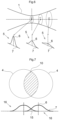
Figure 1 .- Schematic of the procedure for cleaning anilox by overlaying laser spot according to the invention. -
Figure 2 .- Representation of a set of laser spots with 30% overlay. -
Figure 3 .- Representation of a set of laser spots with 33% overlay. -
Figure 4 .- Representation of a set of laser spots with 50% overlay. -
Figure 5 .- Representation of a set of laser spots with 75% overlay. -
Figure 6 .- Diagram of the Gaussian profile change according to the diameter of the spot. -
Figure 7 .- Energic distribution diagram for two laser spots overlaying by 50 %. -
Figure 8 .- Schematic representation of the helical path describing the laser sweep cleaning-active zone on anilox surface. - The novel anilox cleaning procedure consists of organizing the succession of laser spot (4) in the cleaning-active zone (19) of the sweep (17) according to an alignment in which the spots partially overlay in the forward direction of the beam (11) and in the direction of the anilox turn (13) by simulating a continuous pulse.
- According to the new procedure, the laser beam (1) generated by the resonator (2) is defocused by a lens (3) that increases the diameter of laser spot (4) that affects the cells from a minimum diameter corresponding to focal spot w0 to a working diameter wN.
- The increase in the diameter of the laser spot (w0 < w1 < w2) also modifies the associated Gaussian profile (5), decreasing the energy intensity in the center (6) and increasing it in the marginal distribution (7), so that at spot w1 and w2 a more homogeneous Gaussian profile is obtained than at focal spot w0.
- Once the working diameter of the wN laser spot has been established, the partial overlap (10) of the laser spots (4) is continued.
- In order for the laser spots incident on the surface of the anilox (9) to partially overlay (10), the pulses of the laser beam (1) are deflected by the galvo mirror (8) which oscillates at a frequency selected according to the frequency of the laser beam pulses (1) and the working diameter wN of the laser spot (4).
- Overlap of laser spots is performed linearly (11) in the forward direction of the resonator (2) and circumferentially (13) in the direction of the anilox (9) turn.
- According to the invention, the percentage overlap of the laser spots in linear direction (11) is set based on (fgalboX ) the oscillation frequency of the galvo system on the X-axis (12), (∅ spot ) the diameter of the laser spot (4), (lbeam ) beam length y (flaser ) the frequency of the pulses of the laser beam (1) according to the expression

- Therefore, it is sufficient to adjust the parameters appropriately to achieve the desired level of overlap.
- Similarly, the circumferential overlap percentage (13) is given by (ωrotranilox ) the linear speed of the anilox (9), (Ø spot ) the diameter of the laser spot (4) and (fgalboY ) the oscillation frequency of the galvo system on the Y-axis (14), according to the following expression

- The partial overlaying of spot increases the energy intensity in the overlap-area (15)
Fig. 7 , as the energy intensity for each spot is added up (16). - In accordance with the foregoing, by combining the forward motion of the resonator (2) and the rotational movement of the anilox turn (9), the cleaning-active zone (19) performs a helical sweep (17) over the anilox (9) in which 100% of the swept surface is irradiated with the appropriate energy density to evaporate the ink in a single pass.
- For this reason, the step (18) of the helical sweep (17) is equivalent to or multiple of the length of the cleaning-active zone (19).
- According to another aspect of the invention, the step (18) of the helical sweep (17) is slightly less than the length of the cleaning-active zone (19) in order to overlap the laser spots at the ends of the sweep area (20). This overlapping is preferably in a proportion equal to that of the linear overlaying (11) of the laser spot (4), which ensures maximum uniformity of irradiation of the anilox surface over the entire sweep area.
Claims (6)
- Cleaning procedure for anilox by overlaying laser spots where a resonator generates a pulsed laser beam incident on the anilox surface as a laser spot to constitute the cleaning-active zone, characterized in that it consists of increasing the diameter of the laser spots (4) above the minimum diameter corresponding to the focal spot w0 to a working diameter wN, defocusing the pulses of the laser beam (1) using a lens (3) and at the same time, with the help of a galvo mirror (8), redirecting the laser pulses in an organized manner to the cleaning-active zone (19) such that the laser spots (4) hitting in the surface of the anilox (9) partially overlay in the linear direction (11) corresponding to the beam advancement and in the circumferential direction (13) corresponding to the direction of the anilox turn, simulating a continuous pulse.
- Cleaning procedure for anilox by overlaying laser spots according to claim 1 characterized in that the percentage overlap of the laser spots (4) in the linear direction (11) is set based on (fgalboX ) the oscillation frequency of the galvo system on the X-axis (12), (Ø spot ) the diameter of the laser spot (4), (lbeam ) beam length and (flaser ) beam frequency according to expression

- Cleaning procedure for anilox by overlaying laser spots according to claim 1 characterized in that the percentage overlay of the laser spots (4) in circumferential direction (13) is set based on (ωrotranilox) the linear speed of the anilox, (Ø spot ) the diameter of the laser spot (4) and (fgalboY ) the oscillation frequency of the galvo system on the Y-axis (14), according to the following expression

- Cleaning procedure for anilox by overlaying laser spots according to claims 1 to 3 characterized the cleaning-active zone (19) performs a helical sweep (17) on the surface of the anilox (9) whose step (18) is equivalent or multiple of the length of the cleaning-active zone (19).
- Cleaning procedure for anilox by overlaying laser spots according to claims 1 to 3, characterised in that the cleaning-active zone (19) performs a helical sweep (17) on the surface of the anilox (9) whose step (18) is slightly less than the length of the cleaning-active zone (19) in order to partially overlap the laser dots at the ends of the swept area (20) in a proportion equal to that of the linear overlaying (11).
- Cleaning procedure for anilox by overlaying laser spots according to claims 1 to 3, characterised in that the percentage of linear overlaying (11) and circumferential overlaying (13) of the laser spot is between 30% and 75%.
Priority Applications (1)
| Application Number | Priority Date | Filing Date | Title |
|---|---|---|---|
| SI202330012T SI4299320T1 (en) | 2022-06-22 | 2023-05-30 | Cleaning procedure for anilox by overlaying laser spots |
Applications Claiming Priority (1)
| Application Number | Priority Date | Filing Date | Title |
|---|---|---|---|
| ES202230556A ES2924438B2 (en) | 2022-06-22 | 2022-06-22 | Laser Point Overlay Anilox Cleaning Procedure |
Publications (3)
| Publication Number | Publication Date |
|---|---|
| EP4299320A2 true EP4299320A2 (en) | 2024-01-03 |
| EP4299320A3 EP4299320A3 (en) | 2024-02-14 |
| EP4299320B1 EP4299320B1 (en) | 2024-09-11 |
Family
ID=83462197
Family Applications (1)
| Application Number | Title | Priority Date | Filing Date |
|---|---|---|---|
| EP23382505.8A Active EP4299320B1 (en) | 2022-06-22 | 2023-05-30 | Cleaning procedure for anilox by overlaying laser spots |
Country Status (6)
| Country | Link |
|---|---|
| US (1) | US12269073B2 (en) |
| EP (1) | EP4299320B1 (en) |
| DK (1) | DK4299320T3 (en) |
| ES (2) | ES2924438B2 (en) |
| PL (1) | PL4299320T3 (en) |
| SI (1) | SI4299320T1 (en) |
Families Citing this family (3)
| Publication number | Priority date | Publication date | Assignee | Title |
|---|---|---|---|---|
| ES2924438B2 (en) * | 2022-06-22 | 2023-02-14 | Teg Tech Research And Development S L | Laser Point Overlay Anilox Cleaning Procedure |
| CN115958020B (en) * | 2023-01-04 | 2025-10-28 | 中国航空制造技术研究院 | A dual-light source composite laser cleaning method and device |
| CN119549475A (en) * | 2024-11-18 | 2025-03-04 | 海目星激光科技集团股份有限公司 | Roller surface cleaning method |
Family Cites Families (11)
| Publication number | Priority date | Publication date | Assignee | Title |
|---|---|---|---|---|
| FR2760403B1 (en) * | 1997-03-05 | 1999-05-14 | Laseralp Ind | LASER CLEANING PROCESS FOR ALL CYLINDERS USED IN PRINTING AND DEVICES IMPLEMENTING SAID METHOD |
| US6354213B1 (en) * | 2000-04-03 | 2002-03-12 | Jerome D. Jenkins | Method and apparatus for cleaning a metering roll of a printing press |
| GB0222341D0 (en) * | 2002-09-26 | 2002-11-06 | British Nuclear Fuels Plc | Surface treatment of concrete |
| JP2011062650A (en) * | 2009-09-18 | 2011-03-31 | Hitachi High-Technologies Corp | Method of cleaning mask for organic el, program, device for cleaning mask for organic el, device for manufacturing organic el display, and organic el display |
| US11047017B2 (en) * | 2014-09-09 | 2021-06-29 | G.C. Laser Systems, Inc. | Laser ablation devices that utilize beam profiling assemblies to clean and process surfaces |
| US9914985B2 (en) * | 2014-09-09 | 2018-03-13 | G.C. Laser Systems, Inc. | Laser ablation and processing methods and systems |
| JP6362053B2 (en) * | 2016-07-28 | 2018-07-25 | 株式会社キヨシ・ネットワーク | Anilox roll cleaning equipment |
| ES2636715B2 (en) * | 2017-06-07 | 2018-02-12 | Sitexco Girona, S.L. | Anilox laser roller cleaning machine and procedure for self-adjusting the laser focal point to the diameter of the anilox roller. |
| DK201800236A1 (en) * | 2018-05-25 | 2019-06-12 | FLEXO WASH HOLDING ApS | Cleaning Apparatus and Method for Laser Cleaning of a Printing Plate |
| CN112676267B (en) * | 2020-12-10 | 2022-05-31 | 中国科学院半导体研究所 | Pulse laser cleaning method |
| ES2924438B2 (en) * | 2022-06-22 | 2023-02-14 | Teg Tech Research And Development S L | Laser Point Overlay Anilox Cleaning Procedure |
-
2022
- 2022-06-22 ES ES202230556A patent/ES2924438B2/en active Active
-
2023
- 2023-05-30 SI SI202330012T patent/SI4299320T1/en unknown
- 2023-05-30 PL PL23382505.8T patent/PL4299320T3/en unknown
- 2023-05-30 DK DK23382505.8T patent/DK4299320T3/en active
- 2023-05-30 ES ES23382505T patent/ES2994612T3/en active Active
- 2023-05-30 EP EP23382505.8A patent/EP4299320B1/en active Active
- 2023-06-06 US US18/329,732 patent/US12269073B2/en active Active
Also Published As
| Publication number | Publication date |
|---|---|
| SI4299320T1 (en) | 2025-03-31 |
| PL4299320T3 (en) | 2025-01-27 |
| EP4299320A3 (en) | 2024-02-14 |
| ES2994612T3 (en) | 2025-01-27 |
| ES2924438B2 (en) | 2023-02-14 |
| ES2924438A1 (en) | 2022-10-06 |
| US12269073B2 (en) | 2025-04-08 |
| US20230415208A1 (en) | 2023-12-28 |
| DK4299320T3 (en) | 2024-11-18 |
| EP4299320B1 (en) | 2024-09-11 |
Similar Documents
| Publication | Publication Date | Title |
|---|---|---|
| EP4299320B1 (en) | Cleaning procedure for anilox by overlaying laser spots | |
| US6231566B1 (en) | Method for scanning a pulsed laser beam for surface ablation | |
| US3848104A (en) | Apparatus for heat treating a surface | |
| US20070016177A1 (en) | Laser ablation apparatus useful for hard tissue removal | |
| CN1224644A (en) | Descaling metal with laser having very short pulse width and high average power | |
| IL262051B (en) | Optical focusing system of an apparatus for cutting-out a human or animal tissue | |
| US8425498B2 (en) | Apparatus for treatment of material, in particular for refractive surgery | |
| CA2940302A1 (en) | Technique for photodisruptive multi-pulse treatment of a material | |
| WO1996034718A1 (en) | Process and device for producing grid steps in the surface of a rotogravure cylinder | |
| JP2022536649A5 (en) | ||
| DE4229397A1 (en) | Appts. for sputtering material from target - comprises high performance laser, frequency multiplier, and laser beam guide | |
| DE2922563C2 (en) | ||
| US5151571A (en) | Electron beam welding | |
| JP7274455B2 (en) | Fiber laser device and method for processing a workpiece | |
| DE10225387A1 (en) | Substrate treatment device using laser beam has rotary mirror deflecting laser beam along different beam paths | |
| DE102004008256B3 (en) | Method for shaping a laser beam, laser processing method | |
| US7191509B2 (en) | Method for adjusting the switch-gap between the contact tongues of a reeds switch | |
| KR102727762B1 (en) | Method for processing materials | |
| DE102021100675B4 (en) | Process for dividing a transparent workpiece | |
| GB1593268A (en) | Methods of and apparatus for effecting localised heating of a workpiece | |
| DE102004041502B4 (en) | Overlap welding method by means of beam welding, in particular by means of laser beam welding, on coated sheets, in particular on galvanized steel sheets | |
| US5938656A (en) | Process and device for correcting the shape of a lens | |
| DE3938221A1 (en) | METHOD FOR PROTECTING A DISC IN GENERATING ELECTRON BEAM IMPULSES | |
| JP2025530175A (en) | Apparatus and method for processing materials with spatially and statistically directed laser pulses around a spatial target value | |
| DE4314601A1 (en) | Apparatus and method for treating grain-orientated workpieces with focussed light |
Legal Events
| Date | Code | Title | Description |
|---|---|---|---|
| PUAI | Public reference made under article 153(3) epc to a published international application that has entered the european phase |
Free format text: ORIGINAL CODE: 0009012 |
|
| STAA | Information on the status of an ep patent application or granted ep patent |
Free format text: STATUS: THE APPLICATION HAS BEEN PUBLISHED |
|
| AK | Designated contracting states |
Kind code of ref document: A2 Designated state(s): AL AT BE BG CH CY CZ DE DK EE ES FI FR GB GR HR HU IE IS IT LI LT LU LV MC ME MK MT NL NO PL PT RO RS SE SI SK SM TR |
|
| PUAL | Search report despatched |
Free format text: ORIGINAL CODE: 0009013 |
|
| AK | Designated contracting states |
Kind code of ref document: A3 Designated state(s): AL AT BE BG CH CY CZ DE DK EE ES FI FR GB GR HR HU IE IS IT LI LT LU LV MC ME MK MT NL NO PL PT RO RS SE SI SK SM TR |
|
| RIC1 | Information provided on ipc code assigned before grant |
Ipc: B41F 35/04 20060101AFI20240111BHEP |
|
| STAA | Information on the status of an ep patent application or granted ep patent |
Free format text: STATUS: REQUEST FOR EXAMINATION WAS MADE |
|
| GRAP | Despatch of communication of intention to grant a patent |
Free format text: ORIGINAL CODE: EPIDOSNIGR1 |
|
| STAA | Information on the status of an ep patent application or granted ep patent |
Free format text: STATUS: GRANT OF PATENT IS INTENDED |
|
| 17P | Request for examination filed |
Effective date: 20240604 |
|
| RBV | Designated contracting states (corrected) |
Designated state(s): AL AT BE BG CH CY CZ DE DK EE ES FI FR GB GR HR HU IE IS IT LI LT LU LV MC ME MK MT NL NO PL PT RO RS SE SI SK SM TR |
|
| GRAS | Grant fee paid |
Free format text: ORIGINAL CODE: EPIDOSNIGR3 |
|
| INTG | Intention to grant announced |
Effective date: 20240704 |
|
| GRAA | (expected) grant |
Free format text: ORIGINAL CODE: 0009210 |
|
| STAA | Information on the status of an ep patent application or granted ep patent |
Free format text: STATUS: THE PATENT HAS BEEN GRANTED |
|
| AK | Designated contracting states |
Kind code of ref document: B1 Designated state(s): AL AT BE BG CH CY CZ DE DK EE ES FI FR GB GR HR HU IE IS IT LI LT LU LV MC ME MK MT NL NO PL PT RO RS SE SI SK SM TR |
|
| REG | Reference to a national code |
Ref country code: GB Ref legal event code: FG4D |
|
| REG | Reference to a national code |
Ref country code: CH Ref legal event code: EP |
|
| REG | Reference to a national code |
Ref country code: DE Ref legal event code: R096 Ref document number: 602023000544 Country of ref document: DE |
|
| REG | Reference to a national code |
Ref country code: IE Ref legal event code: FG4D |
|
| REG | Reference to a national code |
Ref country code: DK Ref legal event code: T3 Effective date: 20241112 |
|
| REG | Reference to a national code |
Ref country code: NL Ref legal event code: FP |
|
| REG | Reference to a national code |
Ref country code: LT Ref legal event code: MG9D |
|
| PG25 | Lapsed in a contracting state [announced via postgrant information from national office to epo] |
Ref country code: NO Free format text: LAPSE BECAUSE OF FAILURE TO SUBMIT A TRANSLATION OF THE DESCRIPTION OR TO PAY THE FEE WITHIN THE PRESCRIBED TIME-LIMIT Effective date: 20241211 |
|
| PG25 | Lapsed in a contracting state [announced via postgrant information from national office to epo] |
Ref country code: GR Free format text: LAPSE BECAUSE OF FAILURE TO SUBMIT A TRANSLATION OF THE DESCRIPTION OR TO PAY THE FEE WITHIN THE PRESCRIBED TIME-LIMIT Effective date: 20241212 Ref country code: FI Free format text: LAPSE BECAUSE OF FAILURE TO SUBMIT A TRANSLATION OF THE DESCRIPTION OR TO PAY THE FEE WITHIN THE PRESCRIBED TIME-LIMIT Effective date: 20240911 |
|
| PG25 | Lapsed in a contracting state [announced via postgrant information from national office to epo] |
Ref country code: BG Free format text: LAPSE BECAUSE OF FAILURE TO SUBMIT A TRANSLATION OF THE DESCRIPTION OR TO PAY THE FEE WITHIN THE PRESCRIBED TIME-LIMIT Effective date: 20240911 |
|
| PG25 | Lapsed in a contracting state [announced via postgrant information from national office to epo] |
Ref country code: LV Free format text: LAPSE BECAUSE OF FAILURE TO SUBMIT A TRANSLATION OF THE DESCRIPTION OR TO PAY THE FEE WITHIN THE PRESCRIBED TIME-LIMIT Effective date: 20240911 |
|
| PG25 | Lapsed in a contracting state [announced via postgrant information from national office to epo] |
Ref country code: HR Free format text: LAPSE BECAUSE OF FAILURE TO SUBMIT A TRANSLATION OF THE DESCRIPTION OR TO PAY THE FEE WITHIN THE PRESCRIBED TIME-LIMIT Effective date: 20240911 |
|
| REG | Reference to a national code |
Ref country code: ES Ref legal event code: FG2A Ref document number: 2994612 Country of ref document: ES Kind code of ref document: T3 Effective date: 20250127 |
|
| PG25 | Lapsed in a contracting state [announced via postgrant information from national office to epo] |
Ref country code: RS Free format text: LAPSE BECAUSE OF FAILURE TO SUBMIT A TRANSLATION OF THE DESCRIPTION OR TO PAY THE FEE WITHIN THE PRESCRIBED TIME-LIMIT Effective date: 20241211 |
|
| PG25 | Lapsed in a contracting state [announced via postgrant information from national office to epo] |
Ref country code: RS Free format text: LAPSE BECAUSE OF FAILURE TO SUBMIT A TRANSLATION OF THE DESCRIPTION OR TO PAY THE FEE WITHIN THE PRESCRIBED TIME-LIMIT Effective date: 20241211 Ref country code: NO Free format text: LAPSE BECAUSE OF FAILURE TO SUBMIT A TRANSLATION OF THE DESCRIPTION OR TO PAY THE FEE WITHIN THE PRESCRIBED TIME-LIMIT Effective date: 20241211 Ref country code: LV Free format text: LAPSE BECAUSE OF FAILURE TO SUBMIT A TRANSLATION OF THE DESCRIPTION OR TO PAY THE FEE WITHIN THE PRESCRIBED TIME-LIMIT Effective date: 20240911 Ref country code: HR Free format text: LAPSE BECAUSE OF FAILURE TO SUBMIT A TRANSLATION OF THE DESCRIPTION OR TO PAY THE FEE WITHIN THE PRESCRIBED TIME-LIMIT Effective date: 20240911 Ref country code: GR Free format text: LAPSE BECAUSE OF FAILURE TO SUBMIT A TRANSLATION OF THE DESCRIPTION OR TO PAY THE FEE WITHIN THE PRESCRIBED TIME-LIMIT Effective date: 20241212 Ref country code: FI Free format text: LAPSE BECAUSE OF FAILURE TO SUBMIT A TRANSLATION OF THE DESCRIPTION OR TO PAY THE FEE WITHIN THE PRESCRIBED TIME-LIMIT Effective date: 20240911 Ref country code: BG Free format text: LAPSE BECAUSE OF FAILURE TO SUBMIT A TRANSLATION OF THE DESCRIPTION OR TO PAY THE FEE WITHIN THE PRESCRIBED TIME-LIMIT Effective date: 20240911 |
|
| REG | Reference to a national code |
Ref country code: AT Ref legal event code: MK05 Ref document number: 1722376 Country of ref document: AT Kind code of ref document: T Effective date: 20240911 |
|
| PG25 | Lapsed in a contracting state [announced via postgrant information from national office to epo] |
Ref country code: IS Free format text: LAPSE BECAUSE OF FAILURE TO SUBMIT A TRANSLATION OF THE DESCRIPTION OR TO PAY THE FEE WITHIN THE PRESCRIBED TIME-LIMIT Effective date: 20250111 Ref country code: PT Free format text: LAPSE BECAUSE OF FAILURE TO SUBMIT A TRANSLATION OF THE DESCRIPTION OR TO PAY THE FEE WITHIN THE PRESCRIBED TIME-LIMIT Effective date: 20250113 |
|
| PG25 | Lapsed in a contracting state [announced via postgrant information from national office to epo] |
Ref country code: RO Free format text: LAPSE BECAUSE OF FAILURE TO SUBMIT A TRANSLATION OF THE DESCRIPTION OR TO PAY THE FEE WITHIN THE PRESCRIBED TIME-LIMIT Effective date: 20240911 Ref country code: SM Free format text: LAPSE BECAUSE OF FAILURE TO SUBMIT A TRANSLATION OF THE DESCRIPTION OR TO PAY THE FEE WITHIN THE PRESCRIBED TIME-LIMIT Effective date: 20240911 |
|
| PG25 | Lapsed in a contracting state [announced via postgrant information from national office to epo] |
Ref country code: EE Free format text: LAPSE BECAUSE OF FAILURE TO SUBMIT A TRANSLATION OF THE DESCRIPTION OR TO PAY THE FEE WITHIN THE PRESCRIBED TIME-LIMIT Effective date: 20240911 Ref country code: AT Free format text: LAPSE BECAUSE OF FAILURE TO SUBMIT A TRANSLATION OF THE DESCRIPTION OR TO PAY THE FEE WITHIN THE PRESCRIBED TIME-LIMIT Effective date: 20240911 |
|
| PG25 | Lapsed in a contracting state [announced via postgrant information from national office to epo] |
Ref country code: SK Free format text: LAPSE BECAUSE OF FAILURE TO SUBMIT A TRANSLATION OF THE DESCRIPTION OR TO PAY THE FEE WITHIN THE PRESCRIBED TIME-LIMIT Effective date: 20240911 |
|
| REG | Reference to a national code |
Ref country code: DE Ref legal event code: R097 Ref document number: 602023000544 Country of ref document: DE |
|
| PGFP | Annual fee paid to national office [announced via postgrant information from national office to epo] |
Ref country code: DE Payment date: 20250226 Year of fee payment: 3 |
|
| PGFP | Annual fee paid to national office [announced via postgrant information from national office to epo] |
Ref country code: ES Payment date: 20250602 Year of fee payment: 3 |
|
| PGFP | Annual fee paid to national office [announced via postgrant information from national office to epo] |
Ref country code: IT Payment date: 20250531 Year of fee payment: 3 |
|
| PLBE | No opposition filed within time limit |
Free format text: ORIGINAL CODE: 0009261 |
|
| STAA | Information on the status of an ep patent application or granted ep patent |
Free format text: STATUS: NO OPPOSITION FILED WITHIN TIME LIMIT |
|
| 26N | No opposition filed |
Effective date: 20250612 |
|
| PG25 | Lapsed in a contracting state [announced via postgrant information from national office to epo] |
Ref country code: SE Free format text: LAPSE BECAUSE OF FAILURE TO SUBMIT A TRANSLATION OF THE DESCRIPTION OR TO PAY THE FEE WITHIN THE PRESCRIBED TIME-LIMIT Effective date: 20240911 |
|
| PG25 | Lapsed in a contracting state [announced via postgrant information from national office to epo] |
Ref country code: LU Free format text: LAPSE BECAUSE OF NON-PAYMENT OF DUE FEES Effective date: 20250530 |
|
| PG25 | Lapsed in a contracting state [announced via postgrant information from national office to epo] |
Ref country code: MC Free format text: LAPSE BECAUSE OF FAILURE TO SUBMIT A TRANSLATION OF THE DESCRIPTION OR TO PAY THE FEE WITHIN THE PRESCRIBED TIME-LIMIT Effective date: 20240911 |
|
| PG25 | Lapsed in a contracting state [announced via postgrant information from national office to epo] |
Ref country code: IE Free format text: LAPSE BECAUSE OF NON-PAYMENT OF DUE FEES Effective date: 20250530 |
|
| PGFP | Annual fee paid to national office [announced via postgrant information from national office to epo] |
Ref country code: DK Payment date: 20260318 Year of fee payment: 4 |
|
| PGFP | Annual fee paid to national office [announced via postgrant information from national office to epo] |
Ref country code: BE Payment date: 20260318 Year of fee payment: 4 |
|
| PGFP | Annual fee paid to national office [announced via postgrant information from national office to epo] |
Ref country code: NL Payment date: 20260318 Year of fee payment: 4 |
|
| PGFP | Annual fee paid to national office [announced via postgrant information from national office to epo] |
Ref country code: FR Payment date: 20260318 Year of fee payment: 4 |
|
| PGFP | Annual fee paid to national office [announced via postgrant information from national office to epo] |
Ref country code: TR Payment date: 20260310 Year of fee payment: 4 |
|
| PGFP | Annual fee paid to national office [announced via postgrant information from national office to epo] |
Ref country code: CZ Payment date: 20260320 Year of fee payment: 4 |
|
| PGFP | Annual fee paid to national office [announced via postgrant information from national office to epo] |
Ref country code: PL Payment date: 20260331 Year of fee payment: 4 |
|
| PGFP | Annual fee paid to national office [announced via postgrant information from national office to epo] |
Ref country code: SI Payment date: 20260312 Year of fee payment: 4 |