EP4299276A1 - Heat bolt unit, die lip adjusting device, extrusion molding die, extrusion molding device, and method for manufacturing heat bolt unit - Google Patents
Heat bolt unit, die lip adjusting device, extrusion molding die, extrusion molding device, and method for manufacturing heat bolt unit Download PDFInfo
- Publication number
- EP4299276A1 EP4299276A1 EP21927949.4A EP21927949A EP4299276A1 EP 4299276 A1 EP4299276 A1 EP 4299276A1 EP 21927949 A EP21927949 A EP 21927949A EP 4299276 A1 EP4299276 A1 EP 4299276A1
- Authority
- EP
- European Patent Office
- Prior art keywords
- heat
- heat bolt
- lip
- bolts
- die
- Prior art date
- Legal status (The legal status is an assumption and is not a legal conclusion. Google has not performed a legal analysis and makes no representation as to the accuracy of the status listed.)
- Pending
Links
Images




Classifications
-
- B—PERFORMING OPERATIONS; TRANSPORTING
- B29—WORKING OF PLASTICS; WORKING OF SUBSTANCES IN A PLASTIC STATE IN GENERAL
- B29C—SHAPING OR JOINING OF PLASTICS; SHAPING OF MATERIAL IN A PLASTIC STATE, NOT OTHERWISE PROVIDED FOR; AFTER-TREATMENT OF THE SHAPED PRODUCTS, e.g. REPAIRING
- B29C48/00—Extrusion moulding, i.e. expressing the moulding material through a die or nozzle which imparts the desired form; Apparatus therefor
- B29C48/25—Component parts, details or accessories; Auxiliary operations
- B29C48/30—Extrusion nozzles or dies
- B29C48/305—Extrusion nozzles or dies having a wide opening, e.g. for forming sheets
- B29C48/31—Extrusion nozzles or dies having a wide opening, e.g. for forming sheets being adjustable, i.e. having adjustable exit sections
-
- B—PERFORMING OPERATIONS; TRANSPORTING
- B29—WORKING OF PLASTICS; WORKING OF SUBSTANCES IN A PLASTIC STATE IN GENERAL
- B29C—SHAPING OR JOINING OF PLASTICS; SHAPING OF MATERIAL IN A PLASTIC STATE, NOT OTHERWISE PROVIDED FOR; AFTER-TREATMENT OF THE SHAPED PRODUCTS, e.g. REPAIRING
- B29C48/00—Extrusion moulding, i.e. expressing the moulding material through a die or nozzle which imparts the desired form; Apparatus therefor
- B29C48/03—Extrusion moulding, i.e. expressing the moulding material through a die or nozzle which imparts the desired form; Apparatus therefor characterised by the shape of the extruded material at extrusion
- B29C48/07—Flat, e.g. panels
- B29C48/08—Flat, e.g. panels flexible, e.g. films
-
- B—PERFORMING OPERATIONS; TRANSPORTING
- B29—WORKING OF PLASTICS; WORKING OF SUBSTANCES IN A PLASTIC STATE IN GENERAL
- B29C—SHAPING OR JOINING OF PLASTICS; SHAPING OF MATERIAL IN A PLASTIC STATE, NOT OTHERWISE PROVIDED FOR; AFTER-TREATMENT OF THE SHAPED PRODUCTS, e.g. REPAIRING
- B29C48/00—Extrusion moulding, i.e. expressing the moulding material through a die or nozzle which imparts the desired form; Apparatus therefor
- B29C48/25—Component parts, details or accessories; Auxiliary operations
- B29C48/30—Extrusion nozzles or dies
- B29C48/305—Extrusion nozzles or dies having a wide opening, e.g. for forming sheets
- B29C48/31—Extrusion nozzles or dies having a wide opening, e.g. for forming sheets being adjustable, i.e. having adjustable exit sections
- B29C48/313—Extrusion nozzles or dies having a wide opening, e.g. for forming sheets being adjustable, i.e. having adjustable exit sections by positioning the die lips
-
- B—PERFORMING OPERATIONS; TRANSPORTING
- B29—WORKING OF PLASTICS; WORKING OF SUBSTANCES IN A PLASTIC STATE IN GENERAL
- B29C—SHAPING OR JOINING OF PLASTICS; SHAPING OF MATERIAL IN A PLASTIC STATE, NOT OTHERWISE PROVIDED FOR; AFTER-TREATMENT OF THE SHAPED PRODUCTS, e.g. REPAIRING
- B29C48/00—Extrusion moulding, i.e. expressing the moulding material through a die or nozzle which imparts the desired form; Apparatus therefor
- B29C48/25—Component parts, details or accessories; Auxiliary operations
- B29C48/78—Thermal treatment of the extrusion moulding material or of preformed parts or layers, e.g. by heating or cooling
- B29C48/86—Thermal treatment of the extrusion moulding material or of preformed parts or layers, e.g. by heating or cooling at the nozzle zone
- B29C48/865—Heating
-
- B—PERFORMING OPERATIONS; TRANSPORTING
- B29—WORKING OF PLASTICS; WORKING OF SUBSTANCES IN A PLASTIC STATE IN GENERAL
- B29C—SHAPING OR JOINING OF PLASTICS; SHAPING OF MATERIAL IN A PLASTIC STATE, NOT OTHERWISE PROVIDED FOR; AFTER-TREATMENT OF THE SHAPED PRODUCTS, e.g. REPAIRING
- B29C48/00—Extrusion moulding, i.e. expressing the moulding material through a die or nozzle which imparts the desired form; Apparatus therefor
- B29C48/25—Component parts, details or accessories; Auxiliary operations
- B29C48/92—Measuring, controlling or regulating
-
- B—PERFORMING OPERATIONS; TRANSPORTING
- B29—WORKING OF PLASTICS; WORKING OF SUBSTANCES IN A PLASTIC STATE IN GENERAL
- B29C—SHAPING OR JOINING OF PLASTICS; SHAPING OF MATERIAL IN A PLASTIC STATE, NOT OTHERWISE PROVIDED FOR; AFTER-TREATMENT OF THE SHAPED PRODUCTS, e.g. REPAIRING
- B29C2948/00—Indexing scheme relating to extrusion moulding
- B29C2948/92—Measuring, controlling or regulating
- B29C2948/92009—Measured parameter
- B29C2948/92114—Dimensions
- B29C2948/92133—Width or height
-
- B—PERFORMING OPERATIONS; TRANSPORTING
- B29—WORKING OF PLASTICS; WORKING OF SUBSTANCES IN A PLASTIC STATE IN GENERAL
- B29C—SHAPING OR JOINING OF PLASTICS; SHAPING OF MATERIAL IN A PLASTIC STATE, NOT OTHERWISE PROVIDED FOR; AFTER-TREATMENT OF THE SHAPED PRODUCTS, e.g. REPAIRING
- B29C2948/00—Indexing scheme relating to extrusion moulding
- B29C2948/92—Measuring, controlling or regulating
- B29C2948/92009—Measured parameter
- B29C2948/92114—Dimensions
- B29C2948/92152—Thickness
-
- B—PERFORMING OPERATIONS; TRANSPORTING
- B29—WORKING OF PLASTICS; WORKING OF SUBSTANCES IN A PLASTIC STATE IN GENERAL
- B29C—SHAPING OR JOINING OF PLASTICS; SHAPING OF MATERIAL IN A PLASTIC STATE, NOT OTHERWISE PROVIDED FOR; AFTER-TREATMENT OF THE SHAPED PRODUCTS, e.g. REPAIRING
- B29C2948/00—Indexing scheme relating to extrusion moulding
- B29C2948/92—Measuring, controlling or regulating
- B29C2948/92504—Controlled parameter
- B29C2948/92609—Dimensions
- B29C2948/92628—Width or height
-
- B—PERFORMING OPERATIONS; TRANSPORTING
- B29—WORKING OF PLASTICS; WORKING OF SUBSTANCES IN A PLASTIC STATE IN GENERAL
- B29C—SHAPING OR JOINING OF PLASTICS; SHAPING OF MATERIAL IN A PLASTIC STATE, NOT OTHERWISE PROVIDED FOR; AFTER-TREATMENT OF THE SHAPED PRODUCTS, e.g. REPAIRING
- B29C2948/00—Indexing scheme relating to extrusion moulding
- B29C2948/92—Measuring, controlling or regulating
- B29C2948/92504—Controlled parameter
- B29C2948/92609—Dimensions
- B29C2948/92647—Thickness
-
- B—PERFORMING OPERATIONS; TRANSPORTING
- B29—WORKING OF PLASTICS; WORKING OF SUBSTANCES IN A PLASTIC STATE IN GENERAL
- B29C—SHAPING OR JOINING OF PLASTICS; SHAPING OF MATERIAL IN A PLASTIC STATE, NOT OTHERWISE PROVIDED FOR; AFTER-TREATMENT OF THE SHAPED PRODUCTS, e.g. REPAIRING
- B29C2948/00—Indexing scheme relating to extrusion moulding
- B29C2948/92—Measuring, controlling or regulating
- B29C2948/92819—Location or phase of control
- B29C2948/92857—Extrusion unit
- B29C2948/92904—Die; Nozzle zone
Definitions
- the present invention relates to a heat bolt unit, a die lip adjusting device, an extrusion molding die, an extrusion molding apparatus, and a method for manufacturing the heat bolt unit.
- T die extrusion molding die that extrudes a film-shaped molten resin from a space (a slit, a gap; hereinafter, referred to as a lip gap) between lips formed at a tip end (see Patent Literature 1, for example).
- Patent Literature 1 discloses a plurality of heat bolts disposed in a width direction of an extrusion molding die in order to control the thickness of a film-shaped molten resin extruded from a lip gap uniformly throughout an entire region in a width direction thereof.
- the heat bolts By manually rotating a lip adjusting screw, the heat bolts move in an axial direction thereof to push or pull one lip (a movable lip, a flexible lip), and locally adjust the lip gap. Thereby, the thickness of the film-shaped molten resin that is pushed out of the lip gap thereafter is controlled to be uniform.
- Patent Literature 1 Japanese Unexamined Patent Application Publication No. 2013-52574
- a heat bolt unit includes a plurality of heat bolts disposed in parallel to one another, and a holding portion holding the plurality of heat bolts.
- the holding portion holds a base end portion of each of the plurality of heat bolts disposed in parallel to one another. In other words, the holding portion holds the plurality of heat bolts disposed in parallel to one another in a cantilever manner.
- the heat bolt unit it is possible to provide the heat bolt unit, the die lip adjusting device, the extrusion molding die, the extrusion molding apparatus, and the method for manufacturing the heat bolt unit that can shorten the time period required for adjustment of the lip gap.
- Fig. 1 is a side view showing the entire configuration of the extrusion molding apparatus 1 according to embodiment 1.
- the extrusion molding apparatus 1 is an apparatus that extrudes a molten resin that is extruded from an extruder 10 (molten resin outlet 11) into a film form from a slit outlet formed at a tip end of a T die 20 (extrusion molding die), that is, a space (a slit, a gap) between lips.
- the film includes a sheet.
- the extrusion molding apparatus 1 includes the extruder 10, the T die 20, and a die lip adjusting device 30.
- the extruder 10 is a device that extrudes a resin that is heated and melted (hereinafter, referred to as a molten resin) from the molten resin outlet 11.
- the extruder 10 may be a screw type extruder or may be a plunger type extruder.
- the T die 20 is a block-shaped member that molds the molten resin extruded from the extruder 10 into a film form.
- the T die 20 is typically made of a metal.
- a base end portion 20b side of the T die 20 is attached to the extruder 10 in a state in which a tip end portion 20a and a base end portion 20b thereof are disposed in a horizontal direction.
- the base end portion 20b side of the T die 20 may be attached to the extruder 10 in a state in which the tip end portion 20a and the base end portion 20b thereof are disposed in a vertical direction.
- the T die 20 includes a pair of die blocks 21 and 22.
- the pair of die blocks 21 and 22 respectively include surfaces facing each other.
- the T die 20 includes an introduction passage 23a, a manifold 23b, and a slit 23c that are formed between the surfaces facing each other.
- the introduction passage 23a is a passage that allows the base end portion 20b of the T die 20 which the extruder 10 faces, and the manifold 23b to communicate with each other.
- the introduction passage 23a extends from the base end portion 20b of the T die 20 toward the tip end portion 20a on an opposite side thereof. A molten resin that is extruded from the extruder 10 is introduced into the introduction passage 23a.
- the manifold 23b is a passage extending in a width direction (direction orthogonal to a paper surface in Fig. 1 ) of the T die 20.
- the manifold 23b is formed in a middle between the base end portion 20b and the tip end portion 20a of the T die 20.
- the molten resin passing through the introduction passage 23a is introduced into the manifold 23b.
- the molten resin passing through the introduction passage 23a passes through the manifold 23b and thereby is pushed and spread in the width direction of the T die 20.
- the introduction passage 23a and the manifold 23b configure a T shape.
- the introduction passage 23a corresponds to a vertical bar configuring the T shape
- the manifold 23b corresponds to a horizontal bar configuring the T shape.
- the slit 23c is a gap that allows the tip end portion 20a of the T die 20 and the manifold 23b to communicate with each other.
- the slit 23c extends in the width direction of the T die 20.
- a pair of die blocks 21 and 22 respectively include tip end portions including taper surfaces 21a and 22a that are inclined toward tip ends.
- the die block 21 includes a movable lip 21b (flexible lip).
- the movable lip 21b can locally displace with a bottom portion of a recessed portion 21c formed at the tip end portion of the die block 21 as a support point by being pushed or pulled by a heat bolt 311 described later.
- a tip end of the tip end portion of the die block 21 is the movable lip 21b.
- the die block 22 includes a fixed lip 22b.
- the fixed lip 22b does not displace even when the movable lip 21b is pushed or pulled by the heat bolt 311 described later.
- a tip end of the tip end portion of the die block 22 is the fixed lip 22b.
- the movable lip 21b, the fixed lip 22b, and the recessed portion 21c extend in the width direction of the T die 20.
- the molten resin extruded from the extruder 10 passes through the introduction passage 23a and the manifold 23b provided inside of the T die 20, in this order. At this time, the molten resin is pushed and spread in the width direction of the T die 20 by passing through the manifold 23b. The molten resin that is pushed and spread in the width direction of the T die 20 passes through the slit 23c, and finally is finally extruded into a film form from a slit outlet formed at a tip end of the T die 20, that is, a space S (a slit, a gap; see Fig. 1 ; hereinafter, referred to as a lip gap S) between the movable lip 21b and the fixed lip 22b.
- a width of the molten resin extruded into a film form corresponds to the width of the T die 20.
- Embodiment 1 is characterized by including a die lip adjusting device 30 that will be described below.
- Fig. 2 is a perspective view of the die lip adjusting device 30 illustrated in Fig. 1 .
- the die lip adjusting device 30 includes a heat bolt unit 31 in which a plurality of heat bolts 311 are unitized into one unit, and an actuator 33 that moves the heat bolt unit 31.
- the actuator 33 moves the heat bolt unit 31, whereby the plurality of heat bolts 311 simultaneously move, and respective tip end portions 311d of the plurality of heat bolts 311 simultaneously push or pull the movable lip 21b.
- the lip gap S is adjusted in a unit of the plurality of heat bolts 311.
- the die lip adjusting device 30 includes the heat bolt unit 31, a guide unit 32, and the actuator 33.
- the heat bolt unit 31 is a member in which the plurality of heat bolts 311 are unitized into one unit.
- the heat bolt unit 31 includes the plurality of heat bolts 311, and a holding portion 312.
- the heat bolt 311 includes a heat bolt body 311a, and a heater 311b (see Fig. 1 ).
- the heat bolt body 311a is a rod-shaped member.
- the heat bolt body 311a is typically made of a metal.
- the heat bolt body 311a is made of a steel (for example, made of SCM440 (chromium molybdenum steel)) with relatively high hardness.
- a shape of the heat bolt body 311a is a quadrangular prism shape.
- the heat bolt body 311a may be made of a material other than a metal, as long as the heat bolt body 311a can thermally expand or contract in an axial direction (a lengthwise direction of the heat bolt body 311a that is a rod-shaped member; see a direction in which an alternate long and short dash line denoted by reference sign AX in Fig. 1 and Fig. 2 ).
- the shape of the heat bolt body 311a may be, for example, a polygonal prim shape or a cylindrical shape other than a quadrangular prism shape.
- the heater 311b is a temperature control unit that controls a temperature of the heat bolt body 311a.
- the heater 311b is a cartridge heater.
- the heat bolt body 311a has a bottomed heater insertion hole 311a1 (see dotted line in Fig. 1 ) that opens on a tip end portion side (lower side in Fig. 1 ) and extends from the tip end portion side toward a base end portion side (upper side in Fig. 1 ).
- a diameter of the heater insertion hole 311a1 is slightly larger than a diameter of the heater 311b (larger by approximately 0.1 mm, for example).
- the heat bolt body 311a has a through-hole 311a2 (hereinafter, referred to as the through-hole 311a2 for control line) that allows the heater insertion hole 311a1 and an outside of the heater insertion hole 311a1 to communicate with each other (see Fig. 1 ).
- the through-hole 311a2 for control line allows, for example, a bottom portion side (upper side in Fig. 1 ) of the heater insertion hole 311a1, and the outside of the heater insertion hole 311a1 (for example, an outer peripheral surface on a side which the taper surface 21a of the die block 21 faces, in the heat bolt body 311a) to communicate with each other.
- the heater 311b is attached to the heat bolt body 311a in a state in which the heater 311b is inserted into the heater insertion hole 311a1. Specifically, the heater 311b is attached to the heat bolt body 311a as follows.
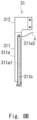
- Fig. 8A is a view showing a way of attaching (inserting) the heater 311b to the heat bolt body 311a
- Fig. 8B is a view showing a state in which the heater 311b is attached to the heat bolt body 311a.
- the heater 311b is firstly inserted into the heater insertion hole 311a1 from a side where a control line c for controlling the heater 311b is electrically connected (see an arrow denoted by reference sign AR2 in Fig. 8A ).
- the heater 311b is disposed in the heater insertion hole 311a1 in a state in which an outer peripheral surface (entire periphery) is surrounded by an inner wall (inner peripheral surface) of the heater insertion hole 311a1.
- the control line c is led outside of the heater insertion hole 311a1 via the through-hole 311a2 for control line.
- the control line c is not led out to a front surface side, but to a die block 21 side (right side in Fig. 8B ). Thereby, when viewed from a front surface direction (see an arrow AR1 in Fig. 1 ), the control line c is prevented from being visually recognized, and a clean look is realized.
- a screw N3 that is inserted into through-holes H2 and H3 that allow one protruded portion 41 of a coupling member 40 and the tip end portion 311d of the heat bolt 311 to communicate with each other, and a through-hole H4 formed in the heater 311b is screwed into the movable lip 21b (die block 31). Thereby, the heater 311b is prevented from slipping out of the heater insertion hole 311a1.
- the heater 311b is attached to the heat bolt body 311a. Since the heater 311b is attached in the state in which the outer peripheral surface (entire periphery) of the heater 311b is surrounded by the inner wall (inner peripheral surface) of the heater insertion hole 311a1 at this time, heat conduction efficiency is improved.
- a heat conducting member (not illustrated) is desirably disposed between the outer peripheral surface (entire periphery) of the heater 311b and the inner wall of the heater insertion hole 311a1. Thereby, the heat conduction efficiency is further improved.
- the heat conducting member is, for example, heat conducting grease, and a heat conducting sheet.
- a control unit (not illustrated) is electrically connected to the heater 311b.
- the control unit controls a heating temperature of the heater 311b.
- the heat bolt body 311a thermally expands or contracts in the axial direction thereof in response to the heating temperature.
- the plurality of heat bolts 311 are disposed in parallel to one another.
- the holding portion 312 is a member that holds the plurality of heat bolts 311 disposed in parallel. Specifically, the holding portion 312 holds the base end portion 311c of each of the plurality of heat bolts 311 disposed in parallel. In other words, the holding portion 312 holds the plurality of heat bolts 311 in a cantilever manner. Thereby, when the respective heat bolts 311 thermally expand or contract in the axial direction thereof, the tip end portions 311d (free end portions) of the respective heat bolts 311 can move in the axial direction thereof with respect to the holding portion 312. The tip end portions 311d of the respective heat bolts 311 that move push and pull the movable lip 21b as described later.
- the holding portion 312 is typically made of a metal. Note that the holding portion 312 may be made of a material other than a metal as long as the holding portion 312 can hold the plurality of heat bolts 311 disposed in parallel. Further, a shape of the holding portion 312 may be any shape.
- the plurality of heat bolts 311 and the holding portion 312 may be an integral object or may be an assembled body in which the plurality of heat bolts 311 and the holding portion 312 that are separate from one another are combined. Note that in Fig. 2 , six heat bolts 311 are illustrated, but the number of heat bolts 311 is not limited to six, as long as the number of heat bolts 311 is plural.
- Fig. 9 is a flowchart of the method for manufacturing the heat bolt unit 31.
- a metal material including the holding portion 312 and a part to be divided is prepared first (step S10).
- the part to be divided refers to a part (not illustrated) before divided into the plurality of heat bolt bodies 311a, of the heat bolt unit 31.
- a plurality of slit-shaped grooves GV1 parallel to one another are formed in the part to be divided (step S11). Thereby, a plurality of heat bolt bodies 311a are formed.
- the slit-shaped groove GV1 can be formed by a rotary blade, or wire cut, for example. Note that the slit-shaped groove GV1 extends from a tip end portion side to a base end portion side of the heat bolt body 311a.
- the heater insertion holes 311a1 are formed in the heat bolt bodies 311a (step S12).
- the heater insertion hole 311a1 can be formed by a drill, for example.
- the heat bolt unit 31 can be manufactured.
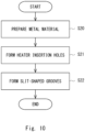
- Fig. 10 is a flowchart of the other method for manufacturing the heat bolt unit 31.
- a metal material including the holding portion 312 and the part to be divided is prepared (step S20).
- the heater insertion holes 311a1 are formed in portions corresponding to the heat bolt bodies 311a, of the part to be divided (step S21).
- a plurality of slit-shaped grooves GV1 parallel to one another are formed in the part to be divided (step S22).
- the heat bolt unit 31 may be manufactured as above. In this way, the heater insertion holes 311a1 can be formed correctly and easily as compared with the case of forming the heater insertion holes 311a1 after formation of the slit-shaped grooves GV1 (see Fig. 9 ).
- the heat bolt unit 31 is slidably attached to the guide unit 32 in the axial direction of the heat bolt 311. Specifically, the heat bolt unit 31 is attached as follows.
- Fig. 3 is a perspective view of the die block 21 to which the die lip adjusting device 30 is attached.
- the die block 22 is not illustrated in Fig. 3 .
- Fig. 4 is a partially enlarged view of a vicinity of the guide protruded portion 324 and the guide groove 312a in Fig. 3 .
- the guide unit 32 is provided with the guide protruded portion 324.
- the holding portion 312 is provided with the guide groove 312a in which the guide protruded portion 324 is inserted.
- the guide unit 32 may be provided with the guide groove 312a, and on the other hand, the holding portion 312 may be provided with the guide protruded portion 324.
- the guide protruded portion 324 and the guide groove 312a respectively extend in the axial direction of the heat bolt 311.
- a cross-sectional shape (cross-sectional shape by a plane orthogonal to an axis of the heat bolt 311) of each of the guide protruded portion 324 and the guide groove 312a is an inverted trapezoidal shape.
- a taper surface 321a (taper surface in an inverted trapezoidal shape) of the guide protruded portion 324 and a taper surface 312a1 (taper surface in an inverted trapezoidal shape) of the guide groove 312a abut on each other (generally in surface contact).
- the heat bolt unit 31 is attached to the guide unit 32 in a state in which the guide protruded portion 324 is inserted in the guide groove 312a, and the taper surface of the guide protruded portion 324 and the taper surface of the guide groove 312a abut on each other.
- the taper surface 321a of the guide protruded portion 324 and the taper surface 312a1 of the guide groove 312a are deviation restraining portions (deviation restraining surfaces) that restrains the heat bolt unit 31 from deviating from the axial direction of the heat bolt 311 (for example, the heat bolt unit 31 floating up from the guide unit 32) when the heat bolt unit 31 slides, by abutting on each other.
- the deviation restraining portions may be surfaces or the like other than the taper surface 321a of the guide protruded portion 324 and the taper surface 312a1 of the guide groove 312a.
- the heat bolt unit 31 slides in the axial direction of the heat bolt 311 along the guide groove 312a, the heat bolt unit 31 is restrained from deviating from the axial direction of the heat bolt 311. In other words, the heat bolt unit 31 can slide in the axial direction of the heat bolt 311 along the guide groove 312a without deviating from the axial direction of the heat bolt 311.
- the guide protruded portion 324 and the guide groove 312a may not be provided (when the heat bolt unit 31 can slide in the axial direction of the heat bolt 311 even if the guide protruded portion 324 and the guide groove 312a are not provided).
- an actuator 33 is coupled to the heat bolt unit 31.
- the actuator 33 is a driving unit that causes the heat bolt unit 31 to slide in the axial direction of the heat bolt 311.
- the actuator 33 includes an actuator body 331, and a rod 332.
- the actuator body 331 is a linear actuator containing a servo motor (not illustrated), and a mechanism (not illustrated) that converts a rotational force of the servo motor into a propulsive force that extrudes or retracts the rod 332 in an axial direction thereof.
- the actuator body 331 is fixed to the holding portion 321 provided at the guide unit 32 by screws N1 and N2.
- the rod 332 is inserted into a through-hole H1 formed in the holding portion 321, and extends in the axial direction of the heat bolt 311.
- a tip end portion of the rod 332 is fixed to the holding portion 312 of the heat bolt unit 31 attached to the guide unit 32.
- the tip end portion of the rod 332 is fixed to the holding portion 312 by the tip end portion being screwed into the holding portion 312.
- a control unit (not illustrated) is electrically connected to the actuator 33.
- the control unit controls a moving direction (an extruding direction or a retracting direction) and a moving amount (an extruding amount or a retracting amount) of the rod 332.
- the actuator 33 extrudes or retracts the rod 332 in the axial direction thereof with respect to the actuator body 331.
- the heat bolt unit 31 to which the rod 332 is fixed slides in the axial direction (an actuator 33 side or a counter-actuator 33 side) of the heat bolt 311 along the guide groove 312a.
- a plurality of die lip adjusting devices 30 are attached to the T die 20 (die block 21) in the width direction thereof as shown in Fig. 3 .
- the die lip adjusting device 30 is attached to the die block 21 by fixing (for example, screw fixing) a fixed portion 322 provided at the guide unit 32 to the die block 21.
- a disposition direction of the plurality of heat bolts 311 coincides with the width direction of the T die 20 (die block 21).
- Fig. 3 an example in which five die lip adjusting devices 30 are attached is illustrated, but regardless of this, any number of die lip adjusting devices 30 greater than or equal to 1 may be attached to the T die 20 (die block 21) according to the width of the T die 20 (die block 21).
- the tip end portion 311d of each of the heat bolts 311 is fixed to the movable lip 21b (see Fig. 1 ). Specifically, the tip end portion 311d of each of the heat bolts 311 is fixed to the movable lip 21b by the coupling member 40 with a U-shaped cross section that is fixed to the movable lip 21b.
- Fig. 5 is a partially enlarged view of a vicinity of the tip end portion 311d of the heat bolt 311 and the movable lip 21b in Fig. 1 .
- the one protruded portion 41 of the coupling member 40 is inserted into a groove 311e formed in the tip end portion 311d of the heat bolt 311 first, and the other protruded portion 42 of the coupling member 40 is inserted into a groove 21b 1 formed in the movable lip 21b.
- a shape of the one protruded portion 41 of the coupling member 40 is a tapered wedge shape
- the one protruded portion 41 of the wedge shape presses the tip end portion 311d of the heat bolt 311 to the other protruded portion 42.
- the tip end portion 311d (tip end surface) of the heat bolt 311 and the movable lip 21b are firmly fixed to each other in a close contact state without gaps between both of them.
- the respective heat bolts 311 are disposed near the taper surface 21a along (facing) the taper surface 21a of the die block 21 as shown in Fig. 1 .
- a heat insulator 50 is attached to the taper surface 21a of the die block 21.
- the lip gap S can be locally adjusted (roughly adjusted) in the unit of the plurality of heat bolts 311.
- the heat bolt unit 31 coupled to the rod 332 slides to the movable lip 21b side along the guide groove 312a provided in the guide unit 32.
- the taper surface 321a of the guide protruded portion 324 and the taper surface 312a1 of the guide groove 312a abut on each other (see Fig. 4 )
- the heat bolt unit 31 slides to the movable lip 21b side along the guide groove 312a provided in the guide unit 32 without deviating from the axial direction of the heat bolt 311.
- the respective tip end portions 311d of the plurality of heat bolts 311 provided in the heat bolt unit 31 simultaneously push the movable lip 21b to the fixed lip 22b side.
- the movable lip 21b locally displaces with the bottom portion of the recessed portion 21c as the support point to move close to the fixed lip 22b.
- the lip gap S is locally narrowed.
- the thickness of the film-shaped molten resin that is thereafter extruded from the lip gap S locally decreases.
- the heat bolt unit 31 coupled to the rod 332 slides to the counter-movable lip 21b side (actuator 33 side) along the guide groove 312a provided in the guide unit 32.
- the heat bolt unit 31 slides to the counter-movable lip 21b side along the guide groove 312a provided in the guide unit 32 without deviating from the axial direction of the heat bolt 311.
- the respective tip end portions 311d of the plurality of heat bolts 311 provided in the heat bolt unit 31 simultaneously pull the movable lip 21b to the counter-movable lip 21b side.
- the tip end portions 311d (tip end surfaces) of the heat bolts 311 and the movable lip 21b are firmly fixed to each other in the state in close contact without gaps between both of them by the coupling member 40 (see Fig. 5 )
- the heat bolts 311 can pull the movable lip 21b to the counter-movable lip 21b side without occurrence of backlash.
- the movable lip 21b locally displaces with the bottom portion of the recessed portion 21c of the movable lip 21b as the support point and separates from the fixed lip 22b.
- the lip gap S is locally widened.
- the thickness of the film-shaped molten resin that is thereafter extruded from the lip gap S locally increases.
- the above adjustment may be carried out before the film-shaped molten resin is extruded from the lip gap S, or may be carried out while the film-shaped molten resin is extruded from the lip gap S.
- the lip gap S can be adjusted locally (finely adjusted) in a unit of the single heat bolt 311.
- the heat bolt 311 thermally expands and increases in the length in the axial direction thereof.
- the tip end portion 311d (free end portion) of the heat bolt 311 moves to the movable lip 21b side with respect to the holding portion 312 to push the movable lip 21b to the fixed lip 22b side.
- the movable lip 21b locally displaces with the bottom portion of the recessed portion 21c as the support point to move close to the fixed lip 22b.
- the lip gap S is locally narrowed.
- the thickness of the film-shaped molten resin that is thereafter extruded from the lip gap S locally decreases.
- the heat bolt 311 contracts and the length in the axial direction thereof decreases.
- the tip end portions 311d (free end portions) of the heat bolts 311 moves to the counter-movable lip 21b side (actuator 33 side) with respect to the holding portion 312 to pull the movable lip 21b to the counter-movable lip 21b side.
- the tip end portions 311d (tip end surfaces) of the heat bolts 311 and the movable lip 21b are firmly fixed to each other in the state in close contact without gaps between both of them by the coupling member 40 (see Fig. 5 ), the heat bolts 311 can pull the movable lip 21b to the counter-movable lip 21b side without occurrence of backlash.
- the movable lip 21b locally displaces with the bottom portion of the recessed portion 21c as the support point to separate from the fixed lip 22b.
- the lip gap S is locally widened.
- the thickness of the film-shaped molten resin that is thereafter extruded from the lip gap S locally increases.
- the above adjustment (fine adjustment) is typically carried out automatically and continuously while the film-shaped molten resin is extruded from the lip gap S.
- Fig. 6 is a graph showing the displacement amount of the movable lip 21b when the lip gap S is adjusted by the plurality (six) of heat bolts 311, and a displacement amount of the movable lip 21b when the lip gap S is adjusted by the single heat bolt 311.
- An axis of abscissas of the graph corresponds to a lip range LA where the tip end portions 311d of the plurality of heat bolts 311 are fixed in Fig. 3 .
- a graph of a solid line shows the displacement amount of the movable lip 21b when the plurality (six) of heat bolts 311 simultaneously adjust the lip gap S by causing the heat bolt unit 31 to slide.
- a graph of a dotted line shows the displacement amount of the movable lip 21b when the lip gap S is adjusted by thermally expanding the single heat bolt 311 (heat bolt 311 in a third position from a right end in Fig. 3 ). Note that the graph of the dotted line is drawn so that a center thereof corresponds to a center of the graph of the solid line.
- the die lip adjusting device 30 includes the heat bolt unit 31 in which the plurality of heat bolts 311 are unitized into one unit, and the actuator 33 that moves the heat bolt unit 31, the following effects are exhibited.
- the actuator 33 moves the heat bolt unit 31, whereby the plurality of heat bolts 311 simultaneously move, and the respective tip end portions 311d of the plurality of heat bolts 311 simultaneously pushes or pulls the movable lip 21b.
- the lip gap S is adjusted in the unit of the plurality of heat bolts 311. Thereby, as compared with the case of adjusting the lip gap S in the unit of the single heat bolt 311, the lip gap S is adjusted in the wider range, so that the time period required for adjustment of the lip gap S can be shortened.
- Embodiment 2 is characterized by including a die lip adjusting device 30A including a lip adjusting screw 34 (lip adjusting bolt) that will be described below, in place of the actuator 33.
- a die lip adjusting device 30A including a lip adjusting screw 34 (lip adjusting bolt) that will be described below, in place of the actuator 33.
- Fig. 7 is a side view showing an entire configuration of an extrusion molding apparatus 1A according to embodiment 2.
- the die lip adjusting device 30A includes a heat bolt unit 31 in which a plurality of heat bolts 311 are unitized into one unit, and the lip adjusting screw 34 that moves the heat bolt unit 31.
- the lip adjusting screw 34 By rotating the lip adjusting screw 34 under manual operation (including a use of a tool), the plurality of heat bolts 311 simultaneously move, and respective tip end portions 311d of the plurality of heat bolts 311 simultaneously push or pull the movable lip 21b. Thereby, the lip gap S is adjusted in a unit of the plurality of heat bolts 311.
- the die lip adjusting device 30A includes the heat bolt unit 31, a guide unit 32, and the lip adjusting screw 34.
- the lip adjusting screw 34 is a driving unit that causes the heat bolt unit 31 to slide in an axial direction of the heat bolt 311.
- the lip adjusting screw 34 is a differential screw in which a pitch of an external screw 341 and a pitch of an internal screw 342 are different from each other (the pitch of the external screw 341 > the pitch of the internal screw 342).
- the external screw 341 of the lip adjusting screw 34 is screwed onto a holding portion 323 provided at the guide unit 32.
- a rod 344 is screwed onto the internal screw 342 of the lip adjusting screw 34.
- the rod 344 extends in the axial direction of the heat bolt 311.
- a tip end portion of the rod 344 is fixed to a holding portion 312 of the heat bolt unit 31 attached to the guide unit 32.
- the tip end portion of the rod 344 is fixed to the holding portion 312 by the tip end portion of the rod 344 being screwed into the holding portion 312.
- the die lip adjusting device 30A of the above-described configuration by rotating the lip adjusting screw 34 under manual operation (including the case of using a tool), the rod 344 is finely fed in an axial direction thereof.
- the lip adjusting screw 34 is rotated once, the rod 344 is finely fed in the axial direction thereof by a difference between the pitch of the external screw 341 and the pitch of the internal screw 342.
- the heat bolt unit 31 to which the rod 344 is fixed slides in the axial direction of the heat bolt 311 (a lip adjusting screw 34 side or a counter-lip adjusting screw 34 side) along a guide groove 312a.
- the lip gap S space between the movable lip 21b and a fixed lip 22
- the lip gap S can locally be adjusted (roughly adjusted) in the unit of the plurality of heat bolts 311. Since a specific adjustment operation is similar to the operation described in embodiment 1 described above, explanation will be omitted.
- the die lip adjusting device 30A of the above-described configuration it is possible to locally adjust (finely adjust) the lip gap S in the unit of the single heat bolt 311 by controlling a heating temperature of a heater 311b. Since a specific adjustment operation is similar to the operation described in embodiment 1 described above, explanation will be omitted.
- the die lip adjusting device 30A includes the heat bolt unit 31 in which the plurality of heat bolts 311 are unitized into one unit, and the lip adjusting screw 34 that moves the heat bolt unit 31, and therefore has the following effect.
- the lip adjusting screw 34 under manual operation (including the case of using a tool)
- the plurality of heat bolts 311 simultaneously move, and the respective tip end portions 311d of the plurality of heat bolts 311 simultaneously push or pull the movable lip 21b.
- the lip gap S is adjusted in the unit of the plurality of heat bolts 311.
- the lip gap S is adjusted in a wider range, so that a time period required for adjustment of the lip gap S can be shortened.
- Embodiment 3 is characterized in that the actuator 33 is an actuator 33B having a rotary shaft described below.
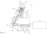
- Fig. 11 is a side view showing an entire configuration of an extrusion molding apparatus 1B according to embodiment 3.
- the die lip adjusting device 30B includes a heat bolt unit 31, a guide unit 32, an actuator 33B, a shaft 35, and a bearing 36.
- the actuator 33B includes an actuator body 33B1, and a rotary shaft 33B2 that is rotated by a servomotor (not illustrated) contained in the actuator body 33B1.
- the actuator body 33B1 is fixed to a holding portion 321 provided at the guide unit 32 by screws N1 and N2.
- the rotary shaft 33B2 is inserted into a through-hole H1 formed in the holding portion 321 and extends in the axial direction of a heat bolt 311.
- a base end portion is coupled (fixed) to the rotary shaft 33B2 of the actuator 33B, and a tip end portion is screwed into the holding portion 312 of the heat bolt unit 31 attached to the guide unit 32.
- the shaft 35 is rotatably supported by the bearing 36 fixed to a fixed portion 322 provided at the guide unit 32.
- the shaft 35 rotates around a same axis AX 33B2 by the rotary shaft 33B2 of the actuator 33B rotating (forward rotation or reverse rotation).
- an amount of screwing of a tip end portion of the shaft 35 to the heat bolt unit 31 (holding portion 312) changes.
- the heat bolt unit 31 into which the tip end portion of the shaft 35 is screwed slides in an axial direction of the heat bolt 311 (an actuator 33B side or a counter-actuator 33B4 side) along a guide groove 312a.
- the holding portion 312 of the heat bolt unit 31 includes a first portion 312A and a second portion 312B that face each other with a slit-shaped groove GV2 formed in the holding portion 312 therebetween.
- the holding portion 312 of the heat bolt unit 31 has a first screw hole H5 and a second screw hole H6 that allow the first portion 312A and the second portion 312B to communicate with each other.
- a tip end portion of the shaft 35 is screwed into the first screw hole H5.
- a groove width adjusting screw N4 for adjusting a groove width of the groove GV2 is screwed into the second screw hole H6.
- Fig. 12 is a modified example of the T die 20 (die block 21).
- the movable lip 21b of the T die 20 (die block 21) of each of the above-described embodiments includes heat bolt fixing portions 21b2 (plural) to which the tip end portions 311d of the heat bolts 311 are fixed, and a groove GV3 may be formed between the heat bolt fixing portions 21b2 adjacent to each other in the movable lip 21b.
- a thickness h1 between the heat bolt fixing portions 21b2 adjacent to each other in the movable lip 21b can be made thinner than a thickness h2 of the heat bolt fixing portion 21b2.
- the heater 311b is inserted into the heater insertion hole 311a1 and is attached to the heat bolt body 311a in the state in which the outer peripheral surface (entire periphery) is surrounded by the inner wall (inner peripheral surface) of the heater insertion hole 311a1, but the present invention is not limited to this.
- the heater 311b may be attached to the heat bolt body 311a in a state in which the heater 311b is inserted into a recessed portion formed on a periphery (outer peripheral surface) of the heat bolt body 311a. Further, the heater 311b may be attached to the heat bolt body 311a in a state in which the heater 311b surrounds the periphery (outer peripheral surface) of the heat bolt body 311a.
- a deformation restraining member for restraining the heat bolts 311 (heat bolt bodies 311a) from deforming may be disposed between the heat bolts 311 adjacent to each other (the slit-shaped groove GV1. See Fig. 2 ).
- the deformation restraining member is a plate-shaped member (for example, a plate-shaped member of a metal) having a thickness that is substantially a groove width of the slit-shaped groove GV1, for example.
- the deformation restraining member is preferably fixed to the heat bolt body 311a by brazing, for example. In this way, it is possible to restrain the heat bolt 311 (heat bolt body 311a) from deforming.
Landscapes
- Engineering & Computer Science (AREA)
- Mechanical Engineering (AREA)
- Manufacturing & Machinery (AREA)
- Physics & Mathematics (AREA)
- Thermal Sciences (AREA)
- Extrusion Moulding Of Plastics Or The Like (AREA)
Abstract
Description
- The present invention relates to a heat bolt unit, a die lip adjusting device, an extrusion molding die, an extrusion molding apparatus, and a method for manufacturing the heat bolt unit.
- There is known an extrusion molding die (T die) that extrudes a film-shaped molten resin from a space (a slit, a gap; hereinafter, referred to as a lip gap) between lips formed at a tip end (see
Patent Literature 1, for example). -
Patent Literature 1 discloses a plurality of heat bolts disposed in a width direction of an extrusion molding die in order to control the thickness of a film-shaped molten resin extruded from a lip gap uniformly throughout an entire region in a width direction thereof. By manually rotating a lip adjusting screw, the heat bolts move in an axial direction thereof to push or pull one lip (a movable lip, a flexible lip), and locally adjust the lip gap. Thereby, the thickness of the film-shaped molten resin that is pushed out of the lip gap thereafter is controlled to be uniform. - Patent Literature 1:
Japanese Unexamined Patent Application Publication No. 2013-52574 - There is a room for improvement because it takes a considerable amount of time to manually rotate lip adjusting screws of a plurality of heat bolts one by one to adjust the lip gap.
- The other problems and new features will become apparent from the description of the present specification and the accompanying drawings.
- A heat bolt unit according to one embodiment includes a plurality of heat bolts disposed in parallel to one another, and a holding portion holding the plurality of heat bolts. The holding portion holds a base end portion of each of the plurality of heat bolts disposed in parallel to one another. In other words, the holding portion holds the plurality of heat bolts disposed in parallel to one another in a cantilever manner.
- According to the one embodiment, it is possible to provide the heat bolt unit, the die lip adjusting device, the extrusion molding die, the extrusion molding apparatus, and the method for manufacturing the heat bolt unit that can shorten the time period required for adjustment of the lip gap.
-
-
Fig. 1 is a side view showing an entire configuration of anextrusion molding apparatus 1 according toembodiment 1; -
Fig. 2 is a perspective view of a die lip adjustingdevice 30 illustrated inFig. 1 ; -
Fig. 3 is a perspective view of adie block 21 to which the dielip adjusting device 30 is attached; -
Fig. 4 is a partially enlarged view of a vicinity of a guide protrudedportion 324 and aguide groove 312a inFig. 3 ; -
Fig. 5 is a partially enlarged view of a vicinity of atip end portion 311d of aheat bolt 311 and amovable lip 21b inFig. 1 ; -
Fig. 6 is a graph showing a displacement amount of themovable lip 21b when a lip gap S is adjusted by a plurality (six) ofheat bolts 311, and a displacement amount of themovable lip 21b when the lip gap S is adjusted by thesingle heat bolt 311; -
Fig. 7 is a side view showing an entire configuration of anextrusion molding apparatus 1A according to embodiment 2; -
Fig. 8A is a view showing a way of attaching (inserting) aheater 311b to aheat bolt body 311a; -
Fig. 8B is a view showing a state in which theheater 311b is attached to theheat bolt body 311a; -
Fig. 9 is a flowchart of a method for manufacturing aheat bolt unit 31; -
Fig. 10 is a flowchart of another method for manufacturing theheat bolt unit 31; -
Fig. 11 is a side view showing an entire configuration of anextrusion molding apparatus 1B according to embodiment 3; and -
Fig. 12 is a modified example of a T die 20 (die block 21). - Hereinafter, specific embodiments will be described in detail with reference to the drawings. However, the present invention is not limited to the following embodiments. Further, in order to clarify the explanation, the following description and drawings are properly simplified.
- First, an entire configuration of an
extrusion molding apparatus 1 according toembodiment 1 will be described with reference toFig. 1. Fig. 1 is a side view showing the entire configuration of theextrusion molding apparatus 1 according toembodiment 1. - The
extrusion molding apparatus 1 is an apparatus that extrudes a molten resin that is extruded from an extruder 10 (molten resin outlet 11) into a film form from a slit outlet formed at a tip end of a T die 20 (extrusion molding die), that is, a space (a slit, a gap) between lips. In the present specification, the film includes a sheet. - As shown in
Fig. 1 , theextrusion molding apparatus 1 includes theextruder 10, the T die 20, and a dielip adjusting device 30. - The
extruder 10 is a device that extrudes a resin that is heated and melted (hereinafter, referred to as a molten resin) from themolten resin outlet 11. Theextruder 10 may be a screw type extruder or may be a plunger type extruder. - Next, a configuration of the
T die 20 will be described with reference toFig. 1 . - The T die 20 is a block-shaped member that molds the molten resin extruded from the
extruder 10 into a film form. The T die 20 is typically made of a metal. - As shown in
Fig. 1 , abase end portion 20b side of theT die 20 is attached to theextruder 10 in a state in which atip end portion 20a and abase end portion 20b thereof are disposed in a horizontal direction. Note that though not illustrated, thebase end portion 20b side of theT die 20 may be attached to theextruder 10 in a state in which thetip end portion 20a and thebase end portion 20b thereof are disposed in a vertical direction. - The T die 20 includes a pair of die
blocks blocks introduction passage 23a, amanifold 23b, and aslit 23c that are formed between the surfaces facing each other. - The
introduction passage 23a is a passage that allows thebase end portion 20b of theT die 20 which the extruder 10 faces, and themanifold 23b to communicate with each other. Theintroduction passage 23a extends from thebase end portion 20b of theT die 20 toward thetip end portion 20a on an opposite side thereof. A molten resin that is extruded from theextruder 10 is introduced into theintroduction passage 23a. - The
manifold 23b is a passage extending in a width direction (direction orthogonal to a paper surface inFig. 1 ) of theT die 20. Themanifold 23b is formed in a middle between thebase end portion 20b and thetip end portion 20a of theT die 20. The molten resin passing through theintroduction passage 23a is introduced into themanifold 23b. The molten resin passing through theintroduction passage 23a passes through themanifold 23b and thereby is pushed and spread in the width direction of theT die 20. Theintroduction passage 23a and themanifold 23b configure a T shape. Theintroduction passage 23a corresponds to a vertical bar configuring the T shape, and themanifold 23b corresponds to a horizontal bar configuring the T shape. - The
slit 23c is a gap that allows thetip end portion 20a of theT die 20 and themanifold 23b to communicate with each other. Theslit 23c extends in the width direction of the T die 20. - A pair of die blocks 21 and 22 respectively include tip end portions including taper surfaces 21a and 22a that are inclined toward tip ends. The
die block 21 includes amovable lip 21b (flexible lip). Themovable lip 21b can locally displace with a bottom portion of a recessedportion 21c formed at the tip end portion of thedie block 21 as a support point by being pushed or pulled by aheat bolt 311 described later. A tip end of the tip end portion of thedie block 21 is themovable lip 21b. - On the other hand, the
die block 22 includes a fixedlip 22b. The fixedlip 22b does not displace even when themovable lip 21b is pushed or pulled by theheat bolt 311 described later. A tip end of the tip end portion of thedie block 22 is the fixedlip 22b. Themovable lip 21b, the fixedlip 22b, and the recessedportion 21c extend in the width direction of the T die 20. - In the T die 20 of the above-described configuration, the molten resin extruded from the
extruder 10 passes through theintroduction passage 23a and the manifold 23b provided inside of the T die 20, in this order. At this time, the molten resin is pushed and spread in the width direction of the T die 20 by passing through the manifold 23b. The molten resin that is pushed and spread in the width direction of the T die 20 passes through theslit 23c, and finally is finally extruded into a film form from a slit outlet formed at a tip end of the T die 20, that is, a space S (a slit, a gap; seeFig. 1 ; hereinafter, referred to as a lip gap S) between themovable lip 21b and the fixedlip 22b. A width of the molten resin extruded into a film form corresponds to the width of the T die 20. -
Embodiment 1 is characterized by including a dielip adjusting device 30 that will be described below.Fig. 2 is a perspective view of the dielip adjusting device 30 illustrated inFig. 1 . - As shown in
Fig. 2 , the dielip adjusting device 30 includes aheat bolt unit 31 in which a plurality ofheat bolts 311 are unitized into one unit, and anactuator 33 that moves theheat bolt unit 31. Theactuator 33 moves theheat bolt unit 31, whereby the plurality ofheat bolts 311 simultaneously move, and respectivetip end portions 311d of the plurality ofheat bolts 311 simultaneously push or pull themovable lip 21b. Thereby, the lip gap S is adjusted in a unit of the plurality ofheat bolts 311. - Hereinafter, a configuration of the die
lip adjusting device 30 will be described in detail. - As shown in
Fig. 2 , the dielip adjusting device 30 includes theheat bolt unit 31, aguide unit 32, and theactuator 33. - The
heat bolt unit 31 is a member in which the plurality ofheat bolts 311 are unitized into one unit. Theheat bolt unit 31 includes the plurality ofheat bolts 311, and a holdingportion 312. - The
heat bolt 311 includes aheat bolt body 311a, and aheater 311b (seeFig. 1 ). - The
heat bolt body 311a is a rod-shaped member. Theheat bolt body 311a is typically made of a metal. For example, theheat bolt body 311a is made of a steel (for example, made of SCM440 (chromium molybdenum steel)) with relatively high hardness. A shape of theheat bolt body 311a is a quadrangular prism shape. Theheat bolt body 311a may be made of a material other than a metal, as long as theheat bolt body 311a can thermally expand or contract in an axial direction (a lengthwise direction of theheat bolt body 311a that is a rod-shaped member; see a direction in which an alternate long and short dash line denoted by reference sign AX inFig. 1 andFig. 2 ). Further, the shape of theheat bolt body 311a may be, for example, a polygonal prim shape or a cylindrical shape other than a quadrangular prism shape. - The
heater 311b is a temperature control unit that controls a temperature of theheat bolt body 311a. For example, theheater 311b is a cartridge heater. - The
heat bolt body 311a has a bottomed heater insertion hole 311a1 (see dotted line inFig. 1 ) that opens on a tip end portion side (lower side inFig. 1 ) and extends from the tip end portion side toward a base end portion side (upper side inFig. 1 ). A diameter of the heater insertion hole 311a1 is slightly larger than a diameter of theheater 311b (larger by approximately 0.1 mm, for example). - Further, the
heat bolt body 311a has a through-hole 311a2 (hereinafter, referred to as the through-hole 311a2 for control line) that allows the heater insertion hole 311a1 and an outside of the heater insertion hole 311a1 to communicate with each other (seeFig. 1 ). The through-hole 311a2 for control line allows, for example, a bottom portion side (upper side inFig. 1 ) of the heater insertion hole 311a1, and the outside of the heater insertion hole 311a1 (for example, an outer peripheral surface on a side which thetaper surface 21a of thedie block 21 faces, in theheat bolt body 311a) to communicate with each other. - The
heater 311b is attached to theheat bolt body 311a in a state in which theheater 311b is inserted into the heater insertion hole 311a1. Specifically, theheater 311b is attached to theheat bolt body 311a as follows. -
Fig. 8A is a view showing a way of attaching (inserting) theheater 311b to theheat bolt body 311a, andFig. 8B is a view showing a state in which theheater 311b is attached to theheat bolt body 311a. - As shown in
Fig. 8A , theheater 311b is firstly inserted into the heater insertion hole 311a1 from a side where a control line c for controlling theheater 311b is electrically connected (see an arrow denoted by reference sign AR2 inFig. 8A ). As shown inFig. 8B , theheater 311b is disposed in the heater insertion hole 311a1 in a state in which an outer peripheral surface (entire periphery) is surrounded by an inner wall (inner peripheral surface) of the heater insertion hole 311a1. At this time, the control line c is led outside of the heater insertion hole 311a1 via the through-hole 311a2 for control line. The control line c is not led out to a front surface side, but to adie block 21 side (right side inFig. 8B ). Thereby, when viewed from a front surface direction (see an arrow AR1 inFig. 1 ), the control line c is prevented from being visually recognized, and a clean look is realized. - Next, as shown in
Fig. 5 , a screw N3 that is inserted into through-holes H2 and H3 that allow one protrudedportion 41 of acoupling member 40 and thetip end portion 311d of theheat bolt 311 to communicate with each other, and a through-hole H4 formed in theheater 311b is screwed into themovable lip 21b (die block 31). Thereby, theheater 311b is prevented from slipping out of the heater insertion hole 311a1. - As above, the
heater 311b is attached to theheat bolt body 311a. Since theheater 311b is attached in the state in which the outer peripheral surface (entire periphery) of theheater 311b is surrounded by the inner wall (inner peripheral surface) of the heater insertion hole 311a1 at this time, heat conduction efficiency is improved. A heat conducting member (not illustrated) is desirably disposed between the outer peripheral surface (entire periphery) of theheater 311b and the inner wall of the heater insertion hole 311a1. Thereby, the heat conduction efficiency is further improved. The heat conducting member is, for example, heat conducting grease, and a heat conducting sheet. - A control unit (not illustrated) is electrically connected to the
heater 311b. The control unit controls a heating temperature of theheater 311b. Theheat bolt body 311a thermally expands or contracts in the axial direction thereof in response to the heating temperature. - The plurality of
heat bolts 311 are disposed in parallel to one another. - The holding
portion 312 is a member that holds the plurality ofheat bolts 311 disposed in parallel. Specifically, the holdingportion 312 holds thebase end portion 311c of each of the plurality ofheat bolts 311 disposed in parallel. In other words, the holdingportion 312 holds the plurality ofheat bolts 311 in a cantilever manner. Thereby, when therespective heat bolts 311 thermally expand or contract in the axial direction thereof, thetip end portions 311d (free end portions) of therespective heat bolts 311 can move in the axial direction thereof with respect to the holdingportion 312. Thetip end portions 311d of therespective heat bolts 311 that move push and pull themovable lip 21b as described later. - The holding
portion 312 is typically made of a metal. Note that the holdingportion 312 may be made of a material other than a metal as long as the holdingportion 312 can hold the plurality ofheat bolts 311 disposed in parallel. Further, a shape of the holdingportion 312 may be any shape. - The plurality of
heat bolts 311 and the holdingportion 312 may be an integral object or may be an assembled body in which the plurality ofheat bolts 311 and the holdingportion 312 that are separate from one another are combined. Note that inFig. 2 , sixheat bolts 311 are illustrated, but the number ofheat bolts 311 is not limited to six, as long as the number ofheat bolts 311 is plural. - Next, a method for manufacturing the
heat bolt unit 31 will be described. -
Fig. 9 is a flowchart of the method for manufacturing theheat bolt unit 31. - As shown in
Fig. 9 , a metal material including the holdingportion 312 and a part to be divided is prepared first (step S10). The part to be divided refers to a part (not illustrated) before divided into the plurality ofheat bolt bodies 311a, of theheat bolt unit 31. - Next, a plurality of slit-shaped grooves GV1 (see
Fig. 2 ) parallel to one another are formed in the part to be divided (step S11). Thereby, a plurality ofheat bolt bodies 311a are formed. The slit-shaped groove GV1 can be formed by a rotary blade, or wire cut, for example. Note that the slit-shaped groove GV1 extends from a tip end portion side to a base end portion side of theheat bolt body 311a. - Next, the heater insertion holes 311a1 are formed in the
heat bolt bodies 311a (step S12). The heater insertion hole 311a1 can be formed by a drill, for example. - As above, the
heat bolt unit 31 can be manufactured. - Next, another method for manufacturing the
heat bolt unit 31 will be described. -
Fig. 10 is a flowchart of the other method for manufacturing theheat bolt unit 31. - As shown in
Fig. 10 , a metal material including the holdingportion 312 and the part to be divided is prepared (step S20). Next, before formation of the slit-shaped groove GV1 (seeFig. 2 ), the heater insertion holes 311a1 are formed in portions corresponding to theheat bolt bodies 311a, of the part to be divided (step S21). Next, a plurality of slit-shaped grooves GV1 (seeFig. 2 ) parallel to one another are formed in the part to be divided (step S22). - The
heat bolt unit 31 may be manufactured as above. In this way, the heater insertion holes 311a1 can be formed correctly and easily as compared with the case of forming the heater insertion holes 311a1 after formation of the slit-shaped grooves GV1 (seeFig. 9 ). - The
heat bolt unit 31 is slidably attached to theguide unit 32 in the axial direction of theheat bolt 311. Specifically, theheat bolt unit 31 is attached as follows. -
Fig. 3 is a perspective view of thedie block 21 to which the dielip adjusting device 30 is attached. For convenience of explanation, thedie block 22 is not illustrated inFig. 3 .Fig. 4 is a partially enlarged view of a vicinity of the guide protrudedportion 324 and theguide groove 312a inFig. 3 . - As shown in
Fig. 3 , theguide unit 32 is provided with the guide protrudedportion 324. On the other hand, the holdingportion 312 is provided with theguide groove 312a in which the guide protrudedportion 324 is inserted. Conversely, theguide unit 32 may be provided with theguide groove 312a, and on the other hand, the holdingportion 312 may be provided with the guide protrudedportion 324. - The guide protruded
portion 324 and theguide groove 312a respectively extend in the axial direction of theheat bolt 311. As shown inFig. 4 , a cross-sectional shape (cross-sectional shape by a plane orthogonal to an axis of the heat bolt 311) of each of the guide protrudedportion 324 and theguide groove 312a is an inverted trapezoidal shape. Ataper surface 321a (taper surface in an inverted trapezoidal shape) of the guide protrudedportion 324 and a taper surface 312a1 (taper surface in an inverted trapezoidal shape) of theguide groove 312a abut on each other (generally in surface contact). - The
heat bolt unit 31 is attached to theguide unit 32 in a state in which the guide protrudedportion 324 is inserted in theguide groove 312a, and the taper surface of the guide protrudedportion 324 and the taper surface of theguide groove 312a abut on each other. Thetaper surface 321a of the guide protrudedportion 324 and the taper surface 312a1 of theguide groove 312a are deviation restraining portions (deviation restraining surfaces) that restrains theheat bolt unit 31 from deviating from the axial direction of the heat bolt 311 (for example, theheat bolt unit 31 floating up from the guide unit 32) when theheat bolt unit 31 slides, by abutting on each other. The deviation restraining portions may be surfaces or the like other than thetaper surface 321a of the guide protrudedportion 324 and the taper surface 312a1 of theguide groove 312a. - Thereby, when the
heat bolt unit 31 slides in the axial direction of theheat bolt 311 along theguide groove 312a, theheat bolt unit 31 is restrained from deviating from the axial direction of theheat bolt 311. In other words, theheat bolt unit 31 can slide in the axial direction of theheat bolt 311 along theguide groove 312a without deviating from the axial direction of theheat bolt 311. - Note that the guide protruded
portion 324 and theguide groove 312a may not be provided (when theheat bolt unit 31 can slide in the axial direction of theheat bolt 311 even if the guide protrudedportion 324 and theguide groove 312a are not provided). - As shown in
Fig. 2 , anactuator 33 is coupled to theheat bolt unit 31. - The
actuator 33 is a driving unit that causes theheat bolt unit 31 to slide in the axial direction of theheat bolt 311. Theactuator 33 includes anactuator body 331, and arod 332. - The
actuator body 331 is a linear actuator containing a servo motor (not illustrated), and a mechanism (not illustrated) that converts a rotational force of the servo motor into a propulsive force that extrudes or retracts therod 332 in an axial direction thereof. - As shown in
Fig. 1 , theactuator body 331 is fixed to the holdingportion 321 provided at theguide unit 32 by screws N1 and N2. Therod 332 is inserted into a through-hole H1 formed in the holdingportion 321, and extends in the axial direction of theheat bolt 311. - A tip end portion of the
rod 332 is fixed to the holdingportion 312 of theheat bolt unit 31 attached to theguide unit 32. For example, the tip end portion of therod 332 is fixed to the holdingportion 312 by the tip end portion being screwed into the holdingportion 312. - A control unit (not illustrated) is electrically connected to the
actuator 33. The control unit controls a moving direction (an extruding direction or a retracting direction) and a moving amount (an extruding amount or a retracting amount) of therod 332. Thereby, theactuator 33 extrudes or retracts therod 332 in the axial direction thereof with respect to theactuator body 331. Thereby, theheat bolt unit 31 to which therod 332 is fixed slides in the axial direction (anactuator 33 side or a counter-actuator 33 side) of theheat bolt 311 along theguide groove 312a. - In order to make a thickness of the film-shaped molten resin that is extruded from the lip gap S uniform throughout an entire region in the width direction of the T die 20, a plurality of die
lip adjusting devices 30 are attached to the T die 20 (die block 21) in the width direction thereof as shown inFig. 3 . The dielip adjusting device 30 is attached to thedie block 21 by fixing (for example, screw fixing) a fixedportion 322 provided at theguide unit 32 to thedie block 21. - At this time, a disposition direction of the plurality of
heat bolts 311 coincides with the width direction of the T die 20 (die block 21). Note that inFig. 3 , an example in which five dielip adjusting devices 30 are attached is illustrated, but regardless of this, any number of dielip adjusting devices 30 greater than or equal to 1 may be attached to the T die 20 (die block 21) according to the width of the T die 20 (die block 21). - The
tip end portion 311d of each of theheat bolts 311 is fixed to themovable lip 21b (seeFig. 1 ). Specifically, thetip end portion 311d of each of theheat bolts 311 is fixed to themovable lip 21b by thecoupling member 40 with a U-shaped cross section that is fixed to themovable lip 21b. - A configuration of fixing the
tip end portion 311d of theheat bolt 311 to themovable lip 21b will be described further in detail. -
Fig. 5 is a partially enlarged view of a vicinity of thetip end portion 311d of theheat bolt 311 and themovable lip 21b inFig. 1 . - As shown in
Fig. 5 , the one protrudedportion 41 of thecoupling member 40 is inserted into agroove 311e formed in thetip end portion 311d of theheat bolt 311 first, and the other protrudedportion 42 of thecoupling member 40 is inserted into agroove 21bmovable lip 21b. - Next, the screw N3 inserted in the through-holes H2 and H3 that allow the one protruded
portion 41 of thecoupling member 40 and thetip end portion 311d of theheat bolt 311 to communicate with each other is screwed into themovable lip 21b. - At this time, since a shape of the one protruded
portion 41 of thecoupling member 40 is a tapered wedge shape, by screwing the screw N3 into themovable lip 21b, the one protrudedportion 41 of the wedge shape presses thetip end portion 311d of theheat bolt 311 to the other protrudedportion 42. Thereby, thetip end portion 311d (tip end surface) of theheat bolt 311 and themovable lip 21b are firmly fixed to each other in a close contact state without gaps between both of them. - Thereby, when the
tip end portion 311d of theheat bolt 311 pulls themovable lip 21b to thecounter-movable lip 21b side (actuator 33 side) as described later, themovable lip 21b can be pulled to thecounter-movable lip 21b side without occurrence of backlash. - When the die
lip adjusting device 30 is attached to the T die 20 as above, the respective heat bolts 311 (heaters 311b) are disposed near thetaper surface 21a along (facing) thetaper surface 21a of thedie block 21 as shown inFig. 1 . Thus, in order to inhibit heat of the respective heat bolts 311 (heaters 311b) from being transferred to thedie block 21, aheat insulator 50 is attached to thetaper surface 21a of thedie block 21. - Next, an operation example of the die
lip adjusting device 30 of the above-described configuration will be described. - According to the die
lip adjusting device 30 of the above-described configuration, by controlling the moving direction (the extruding direction or the retracting direction) and the moving amount (the extruding amount or the retracting amount) of therod 332, the lip gap S can be locally adjusted (roughly adjusted) in the unit of the plurality ofheat bolts 311. - Specifically, by extruding the
rod 332 in the extruding direction by a predetermined amount by theactuator 33, theheat bolt unit 31 coupled to therod 332 slides to themovable lip 21b side along theguide groove 312a provided in theguide unit 32. At this time, since thetaper surface 321a of the guide protrudedportion 324 and the taper surface 312a1 of theguide groove 312a abut on each other (seeFig. 4 ), theheat bolt unit 31 slides to themovable lip 21b side along theguide groove 312a provided in theguide unit 32 without deviating from the axial direction of theheat bolt 311. - Thereby, the respective
tip end portions 311d of the plurality ofheat bolts 311 provided in theheat bolt unit 31 simultaneously push themovable lip 21b to the fixedlip 22b side. Thereby, themovable lip 21b locally displaces with the bottom portion of the recessedportion 21c as the support point to move close to the fixedlip 22b. Thereby, the lip gap S is locally narrowed. As a result, the thickness of the film-shaped molten resin that is thereafter extruded from the lip gap S locally decreases. - Conversely, by pulling the
rod 332 in the retracting direction by a predetermined amount by theactuator 33, theheat bolt unit 31 coupled to therod 332 slides to thecounter-movable lip 21b side (actuator 33 side) along theguide groove 312a provided in theguide unit 32. At this time, since thetaper surface 321a of the guide protrudedportion 324 and the taper surface 312a1 of theguide groove 312a abut on each other (seeFig. 4 ), theheat bolt unit 31 slides to thecounter-movable lip 21b side along theguide groove 312a provided in theguide unit 32 without deviating from the axial direction of theheat bolt 311. - Thereby, the respective
tip end portions 311d of the plurality ofheat bolts 311 provided in theheat bolt unit 31 simultaneously pull themovable lip 21b to thecounter-movable lip 21b side. At this time, since thetip end portions 311d (tip end surfaces) of theheat bolts 311 and themovable lip 21b are firmly fixed to each other in the state in close contact without gaps between both of them by the coupling member 40 (seeFig. 5 ), theheat bolts 311 can pull themovable lip 21b to thecounter-movable lip 21b side without occurrence of backlash. - Thereby, the
movable lip 21b locally displaces with the bottom portion of the recessedportion 21c of themovable lip 21b as the support point and separates from the fixedlip 22b. Thereby, the lip gap S is locally widened. As a result, the thickness of the film-shaped molten resin that is thereafter extruded from the lip gap S locally increases. - The above adjustment (rough adjustment) may be carried out before the film-shaped molten resin is extruded from the lip gap S, or may be carried out while the film-shaped molten resin is extruded from the lip gap S.
- Further, according to the die
lip adjusting device 30 of the above-described configuration, by controlling the heating temperature of theheater 311b, the lip gap S can be adjusted locally (finely adjusted) in a unit of thesingle heat bolt 311. - Specifically, by increasing the heating temperature of the
heater 311b, theheat bolt 311 thermally expands and increases in the length in the axial direction thereof. At this time, since theheat bolt 311 is held by the holdingportion 312 in a cantilever manner, thetip end portion 311d (free end portion) of theheat bolt 311 moves to themovable lip 21b side with respect to the holdingportion 312 to push themovable lip 21b to the fixedlip 22b side. - Thereby, the
movable lip 21b locally displaces with the bottom portion of the recessedportion 21c as the support point to move close to the fixedlip 22b. Thereby, the lip gap S is locally narrowed. As a result, the thickness of the film-shaped molten resin that is thereafter extruded from the lip gap S locally decreases. - Conversely, by decreasing the heating temperature of the
heater 311b, theheat bolt 311 contracts and the length in the axial direction thereof decreases. At this time, since theheat bolts 311 are held by the holdingportion 312 in a cantilever manner, thetip end portions 311d (free end portions) of theheat bolts 311 moves to thecounter-movable lip 21b side (actuator 33 side) with respect to the holdingportion 312 to pull themovable lip 21b to thecounter-movable lip 21b side. At this time, since thetip end portions 311d (tip end surfaces) of theheat bolts 311 and themovable lip 21b are firmly fixed to each other in the state in close contact without gaps between both of them by the coupling member 40 (seeFig. 5 ), theheat bolts 311 can pull themovable lip 21b to thecounter-movable lip 21b side without occurrence of backlash. - Thereby, the
movable lip 21b locally displaces with the bottom portion of the recessedportion 21c as the support point to separate from the fixedlip 22b. Thereby, the lip gap S is locally widened. As a result, the thickness of the film-shaped molten resin that is thereafter extruded from the lip gap S locally increases. - The above adjustment (fine adjustment) is typically carried out automatically and continuously while the film-shaped molten resin is extruded from the lip gap S.
- Next, a displacement amount of the
movable lip 21b when the lip gap S is adjusted by the plurality ofheat bolts 311, and a displacement amount of themovable lip 21b when the lip gap S is adjusted by thesingle heat bolt 311 will be described. -
Fig. 6 is a graph showing the displacement amount of themovable lip 21b when the lip gap S is adjusted by the plurality (six) ofheat bolts 311, and a displacement amount of themovable lip 21b when the lip gap S is adjusted by thesingle heat bolt 311. An axis of abscissas of the graph corresponds to a lip range LA where thetip end portions 311d of the plurality ofheat bolts 311 are fixed inFig. 3 . - In
Fig. 6 , a graph of a solid line shows the displacement amount of themovable lip 21b when the plurality (six) ofheat bolts 311 simultaneously adjust the lip gap S by causing theheat bolt unit 31 to slide. On the other hand, a graph of a dotted line shows the displacement amount of themovable lip 21b when the lip gap S is adjusted by thermally expanding the single heat bolt 311 (heat bolt 311 in a third position from a right end inFig. 3 ). Note that the graph of the dotted line is drawn so that a center thereof corresponds to a center of the graph of the solid line. - Referring to
Fig. 6 , it is found that when the lip gap S is adjusted simultaneously by the plurality ofheat bolts 311, that is, in the unit of the plurality ofheat bolts 311, the lip gap S is adjusted in a wider range and therefore, a time period required for adjustment of the lip gap S can be shortened, as compared with the case in which the lip gap S is adjusted by thesingle heat bolt 311, that is, in the unit of thesingle heat bolt 311. - As described above, according to
embodiment 1, the dielip adjusting device 30 includes theheat bolt unit 31 in which the plurality ofheat bolts 311 are unitized into one unit, and theactuator 33 that moves theheat bolt unit 31, the following effects are exhibited. In other words, theactuator 33 moves theheat bolt unit 31, whereby the plurality ofheat bolts 311 simultaneously move, and the respectivetip end portions 311d of the plurality ofheat bolts 311 simultaneously pushes or pulls themovable lip 21b. - Thereby, the lip gap S is adjusted in the unit of the plurality of
heat bolts 311. Thereby, as compared with the case of adjusting the lip gap S in the unit of thesingle heat bolt 311, the lip gap S is adjusted in the wider range, so that the time period required for adjustment of the lip gap S can be shortened. - Next, embodiment 2 will be described in detail with reference to the drawings.
- Embodiment 2 is characterized by including a die
lip adjusting device 30A including a lip adjusting screw 34 (lip adjusting bolt) that will be described below, in place of theactuator 33. -
Fig. 7 is a side view showing an entire configuration of anextrusion molding apparatus 1A according to embodiment 2. - As shown in
Fig. 7 , the dielip adjusting device 30A includes aheat bolt unit 31 in which a plurality ofheat bolts 311 are unitized into one unit, and thelip adjusting screw 34 that moves theheat bolt unit 31. By rotating thelip adjusting screw 34 under manual operation (including a use of a tool), the plurality ofheat bolts 311 simultaneously move, and respectivetip end portions 311d of the plurality ofheat bolts 311 simultaneously push or pull themovable lip 21b. Thereby, the lip gap S is adjusted in a unit of the plurality ofheat bolts 311. - Hereinafter, concerning a configuration of the die
lip adjusting device 30A, a difference fromembodiment 1 will be mainly described. The same components as those ofembodiment 1 are assigned with the same reference signs, and explanation is properly omitted. - As shown in
Fig. 7 , the dielip adjusting device 30A includes theheat bolt unit 31, aguide unit 32, and thelip adjusting screw 34. - The
lip adjusting screw 34 is a driving unit that causes theheat bolt unit 31 to slide in an axial direction of theheat bolt 311. Thelip adjusting screw 34 is a differential screw in which a pitch of anexternal screw 341 and a pitch of an internal screw 342 are different from each other (the pitch of theexternal screw 341 > the pitch of the internal screw 342). - The
external screw 341 of thelip adjusting screw 34 is screwed onto a holdingportion 323 provided at theguide unit 32. Arod 344 is screwed onto the internal screw 342 of thelip adjusting screw 34. Therod 344 extends in the axial direction of theheat bolt 311. A tip end portion of therod 344 is fixed to a holdingportion 312 of theheat bolt unit 31 attached to theguide unit 32. For example, the tip end portion of therod 344 is fixed to the holdingportion 312 by the tip end portion of therod 344 being screwed into the holdingportion 312. - Next, an operation example of the die
lip adjusting device 30A of the above-described configuration will be described. - According to the die
lip adjusting device 30A of the above-described configuration, by rotating thelip adjusting screw 34 under manual operation (including the case of using a tool), therod 344 is finely fed in an axial direction thereof. For example, when thelip adjusting screw 34 is rotated once, therod 344 is finely fed in the axial direction thereof by a difference between the pitch of theexternal screw 341 and the pitch of the internal screw 342. - Thereby, the
heat bolt unit 31 to which therod 344 is fixed slides in the axial direction of the heat bolt 311 (alip adjusting screw 34 side or acounter-lip adjusting screw 34 side) along aguide groove 312a. Thereby, the lip gap S (space between themovable lip 21b and a fixed lip 22) can locally be adjusted (roughly adjusted) in the unit of the plurality ofheat bolts 311. Since a specific adjustment operation is similar to the operation described inembodiment 1 described above, explanation will be omitted. - Further, according to the die
lip adjusting device 30A of the above-described configuration, it is possible to locally adjust (finely adjust) the lip gap S in the unit of thesingle heat bolt 311 by controlling a heating temperature of aheater 311b. Since a specific adjustment operation is similar to the operation described inembodiment 1 described above, explanation will be omitted. - As described above, according to embodiment 2, the die
lip adjusting device 30A includes theheat bolt unit 31 in which the plurality ofheat bolts 311 are unitized into one unit, and thelip adjusting screw 34 that moves theheat bolt unit 31, and therefore has the following effect. In other words, by rotating thelip adjusting screw 34 under manual operation (including the case of using a tool), the plurality ofheat bolts 311 simultaneously move, and the respectivetip end portions 311d of the plurality ofheat bolts 311 simultaneously push or pull themovable lip 21b. Thereby, the lip gap S is adjusted in the unit of the plurality ofheat bolts 311. Thereby, as compared with the case of adjusting the lip gap S in the unit of thesingle heat bolt 311, the lip gap S is adjusted in a wider range, so that a time period required for adjustment of the lip gap S can be shortened. - Next, embodiment 3 will be described in detail with reference to the drawings.
- Embodiment 3 is characterized in that the
actuator 33 is an actuator 33B having a rotary shaft described below. -
Fig. 11 is a side view showing an entire configuration of anextrusion molding apparatus 1B according to embodiment 3. - Hereinafter, concerning a configuration of the die
lip adjusting device 30B, a difference fromembodiment 1 will be mainly described. The same components as those ofembodiment 1 will be assigned with the same reference signs, and explanation will be properly omitted. - As shown in
Fig. 11 , the dielip adjusting device 30B includes aheat bolt unit 31, aguide unit 32, anactuator 33B, ashaft 35, and abearing 36. - The
actuator 33B includes an actuator body 33B1, and a rotary shaft 33B2 that is rotated by a servomotor (not illustrated) contained in the actuator body 33B1. - As shown in
Fig. 11 , the actuator body 33B1 is fixed to a holdingportion 321 provided at theguide unit 32 by screws N1 and N2. The rotary shaft 33B2 is inserted into a through-hole H1 formed in the holdingportion 321 and extends in the axial direction of aheat bolt 311. - In the
shaft 35, a base end portion is coupled (fixed) to the rotary shaft 33B2 of theactuator 33B, and a tip end portion is screwed into the holdingportion 312 of theheat bolt unit 31 attached to theguide unit 32. Theshaft 35 is rotatably supported by the bearing 36 fixed to a fixedportion 322 provided at theguide unit 32. Theshaft 35 rotates around a same axis AX33B2 by the rotary shaft 33B2 of the actuator 33B rotating (forward rotation or reverse rotation). Thereby, an amount of screwing of a tip end portion of theshaft 35 to the heat bolt unit 31 (holding portion 312) changes. As a result, theheat bolt unit 31 into which the tip end portion of theshaft 35 is screwed slides in an axial direction of the heat bolt 311 (anactuator 33B side or a counter-actuator 33B4 side) along aguide groove 312a. - Next, a configuration for inhibiting a backlash from occurring when the
heat bolt unit 31 slides as described above will be described. - The holding
portion 312 of theheat bolt unit 31 includes afirst portion 312A and a second portion 312B that face each other with a slit-shaped groove GV2 formed in the holdingportion 312 therebetween. - The holding
portion 312 of theheat bolt unit 31 has a first screw hole H5 and a second screw hole H6 that allow thefirst portion 312A and the second portion 312B to communicate with each other. - A tip end portion of the
shaft 35 is screwed into the first screw hole H5. A groove width adjusting screw N4 for adjusting a groove width of the groove GV2 is screwed into the second screw hole H6. By tightening the groove width adjusting screw N4, theheat bolt unit 31 can slide without occurrence of backlash. A degree to which the groove width adjusting screw N4 is tightened is such that backlash does not occur, for example, 1 Nm or less. - Note that an operation example of the die
lip adjusting device 30B of the above-described configuration is similar to that of the dielip adjusting device 30 ofembodiment 1, and therefore explanation is omitted. - Next, a modified example will be described.
-
Fig. 12 is a modified example of the T die 20 (die block 21). - As shown in
Fig. 12 , themovable lip 21b of the T die 20 (die block 21) of each of the above-described embodiments includes heat bolt fixing portions 21b2 (plural) to which thetip end portions 311d of theheat bolts 311 are fixed, and a groove GV3 may be formed between the heat bolt fixing portions 21b2 adjacent to each other in themovable lip 21b. - In this way, a thickness h1 between the heat bolt fixing portions 21b2 adjacent to each other in the
movable lip 21b can be made thinner than a thickness h2 of the heat bolt fixing portion 21b2. Thereby, even if a pitch P between the heat bolts 311 (and between the heat bolt fixing portions 21b2) is narrowed, themovable lip 21b can be locally displaced in a unit of thesingle heat bolt 311. As a result, the lip gap S can be locally adjusted (finely adjusted) in the unit of thesingle heat bolt 311. - Further, in each of the above-described embodiments, the example is described, in which the
heater 311b is inserted into the heater insertion hole 311a1 and is attached to theheat bolt body 311a in the state in which the outer peripheral surface (entire periphery) is surrounded by the inner wall (inner peripheral surface) of the heater insertion hole 311a1, but the present invention is not limited to this. - For example, the
heater 311b may be attached to theheat bolt body 311a in a state in which theheater 311b is inserted into a recessed portion formed on a periphery (outer peripheral surface) of theheat bolt body 311a. Further, theheater 311b may be attached to theheat bolt body 311a in a state in which theheater 311b surrounds the periphery (outer peripheral surface) of theheat bolt body 311a. - Note that though not illustrated, in each of the above-described embodiments, a deformation restraining member for restraining the heat bolts 311 (
heat bolt bodies 311a) from deforming may be disposed between theheat bolts 311 adjacent to each other (the slit-shaped groove GV1. SeeFig. 2 ). The deformation restraining member is a plate-shaped member (for example, a plate-shaped member of a metal) having a thickness that is substantially a groove width of the slit-shaped groove GV1, for example. The deformation restraining member is preferably fixed to theheat bolt body 311a by brazing, for example. In this way, it is possible to restrain the heat bolt 311 (heat bolt body 311a) from deforming. - The invention made by the present inventor is specifically described based on the embodiments thus far, but the present invention is not limited to the embodiments that are already described, and various changes can be made within the range without departing from the gist of the invention.
-
- 1, 1A
- EXTRUSION MOLDING APPARATUS
- 10
- EXTRUDER
- 11
- MOLTEN RESIN OUTLET
- 20
- T DIE
- 20a
- TIP END PORTION
- 20b
- BASE END PORTION
- 21
- DIE BLOCK
- 21a
- TAPER SURFACE
- 21b
- MOVABLE LIP
- 21b1
- GROOVE
- 21c
- RECESSED PORTION
- 22
- DIE BLOCK
- 22a
- TAPER SURFACE
- 22b
- FIXED LIP
- 23a
- INTRODUCTION PASSAGE
- 23b
- MANIFOLD
- 23c
- SLIT
- 30, 30A
- DIE LIP ADJUSTING DEVICE
- 31
- HEAT BOLT UNIT
- 32
- GUIDE UNIT
- 33
- ACTUATOR
- 34
- LIP ADJUSTING SCREW
- 40
- COUPLING MEMBER
- 41,
- 42PROTRUDED PORTION
- 50
- HEAT INSULATOR
- 311
- HEAT BOLT
- 311a
- HEAT BOLT BODY
- 311a1
- RECESSED PORTION
- 311b
- HEATER
- 311c
- BASE END PORTION
- 311d
- TIP END PORTION
- 311e
- GROOVE
- 312
- HOLDING PORTION
- 312a
- GUIDE GROOVE
- 312a1
- TAPER SURFACE
- 321
- HOLDING PORTION
- 321a
- TAPER SURFACE
- 322
- FIXED PORTION
- 323
- HOLDING PORTION
- 324
- GUIDE PROTRUDED PORTION
- 331
- ACTUATOR BODY
- 332
- ROD
- 341
- EXTERNAL SCREW
- 342
- INTERNAL SCREW
- 344
- ROD
- H1, H2
- THROUGH-HOLE
- LA
- LIP RANGE
- N1-N3
- SCREW
- S
- LIP GAP
Claims (20)
- A heat bolt unit, comprising;a plurality of heat bolts each including a heat bolt body and a heater that controls a temperature of the heat bolt body; anda holding portion configured to hold the plurality of heat bolts, whereinthe plurality of heat bolts are disposed in parallel to one another, andthe holding portion holds a base end portion of each of the plurality of heat bolts disposed in parallel to one another.
- The heat bolt unit according to claim 1, whereinthe heat bolt body has a heater insertion hole that opens on a tip end portion side and extends from the tip end portion side to a base end portion side, andthe heater is attached to the heat bolt body in a state in which the heater is inserted into the heater insertion hole.
- The heat bolt unit according to claim 1 or 2, wherein the heat bolt body has a through-hole for control wire that allows the heater insertion hole and an outside of the heater insertion hole to communicate with each other.
- The heat bolt unit according to any one of claims 1 to 3, wherein a heat conducting member is disposed between the heater inserted into the heater insertion hole and an inner wall of the heater insertion hole.
- The heat bolt unit according to any one of claims 1 to 4, whereinthe holding portion includes a first portion and a second portion that face each other with a slit-shaped groove formed in the holding portion therebetween,the holding portion has a first screw hole and a second screw hole that allow the first portion and the second portion to communicate with each other,the first screw hole is a screw hole into which a rotary shaft rotated by an actuator is screwed, andthe second screw hole is a screw hole into which a groove width adjusting screw for adjusting a groove width of the groove is screwed.
- The heat bolt unit according to any one of claims 1 to 5, wherein a deformation restraining member for restraining the heat bolt from deforming is disposed between the heat bolts adjacent to each other.
- The heat bolt unit according to any one of claims 1 to 6, wherein the plurality of heat bolts and the holding portion are an integral object of a metal.
- A die lip adjusting device, comprising:the heat bolt unit according to any one of claims 1 to 7;a guide unit to which the heat bolt unit is slidably attached in an axial direction of the heat bolt; anda driving unit that causes the heat bolt unit to slide in the axial direction of the heat bolt.
- The die lip adjusting device according to claim 8, further comprising:a guide protruded portion; anda guide groove into which the guide protruded portion is inserted,wherein of the guide protruded portion and the guide groove, one is provided in the holding portion, and the other is provided in the guide unit.
- The die lip adjusting device according to claim 9, wherein the guide protruded portion and the guide groove respectively include deviation restraining portions that restrain the heat bolt unit from deviating from the axial direction of the heat bolt when the heat bolt unit slides by abutting on each other.
- The die lip adjusting device according to claim 10, whereina cross-sectional shape of each of the guide protruded portion and the guide groove is an inverted trapezoidal shape, andthe deviation restraining portions are a taper surface in the inverted trapezoidal shape of the guide protruded portion and a taper surface in the inverted trapezoidal shape of the guide groove.
- The die lip adjusting device according to any one of claims 8 to 11, wherein the driving unit is an actuator that is coupled to the heat bolt unit and causes the heat bolt unit to slide in the axial direction of the heat bolt.
- The die lip adjusting device according to claim 12, wherein the actuator includes a servomotor.
- The die lip adjusting device according to any one of claims 8 to 11, wherein the driving unit is a lip adjusting screw that is coupled to the heat bolt unit and causes the heat bolt unit to slide in the axial direction of the heat bolt.
- An extrusion molding die, comprising:the die lip adjusting device according to any one of claims 8 to 14; anda movable lip to which respective tip end portions of the plurality of heat bolts are fixed.
- The extrusion molding die according to claim 15, whereinthe movable lip includes heat bolt fixing portions to which the tip end portions of the heat bolts are fixed, anda groove is formed between the heat bolt fixing portions adjacent to each other, in the movable lip.
- An extrusion molding apparatus, comprising the extrusion molding die according to claim 15 or 16.
- A method for manufacturing a heat bolt unit including a plurality of heat bolts disposed in parallel to one another, and a holding portion that holds respective base end portions of the plurality of heat bolts, the method comprising the steps of:preparing a metal material including the holding portion and a part to be divided; andforming the plurality of heat bolts by forming, in the part to be divided, a plurality of slit-shaped grooves parallel to one another.
- The method for manufacturing a heat bolt unit according to claim 18, further comprising a step of forming, in the heat bolts, heater insertion holes each opening on a tip end portion side and extending from the tip end portion side to a base end portion side.
- The method for manufacturing a heat bolt unit according to claim 18, further comprising:a step of forming heater insertion holes in portions corresponding to the heat bolts, of the part to be divided, the heater insertion holes each opening on a tip end portion side and extending from the tip end portion side toward a base end portion side,wherein the step of forming the plurality of heat bolts comprises forming the plurality of heat bolts in which the heater insertion holes are formed, by forming, in the part to be divided, a plurality of slit-shaped grooves parallel to one another.
Applications Claiming Priority (1)
| Application Number | Priority Date | Filing Date | Title |
|---|---|---|---|
| PCT/JP2021/007561 WO2022180850A1 (en) | 2021-02-26 | 2021-02-26 | Heat bolt unit, die lip adjusting device, extrusion molding die, extrusion molding device, and method for manufacturing heat bolt unit |
Publications (2)
| Publication Number | Publication Date |
|---|---|
| EP4299276A1 true EP4299276A1 (en) | 2024-01-03 |
| EP4299276A4 EP4299276A4 (en) | 2025-01-22 |
Family
ID=83048739
Family Applications (1)
| Application Number | Title | Priority Date | Filing Date |
|---|---|---|---|
| EP21927949.4A Pending EP4299276A4 (en) | 2021-02-26 | 2021-02-26 | HEAT BOLT UNIT, DIE CLIP ADJUSTMENT DEVICE, EXTRUSION TOOL, EXTRUSION DEVICE AND METHOD FOR MANUFACTURING A HEAT BOLT UNIT |
Country Status (6)
| Country | Link |
|---|---|
| US (1) | US12594710B2 (en) |
| EP (1) | EP4299276A4 (en) |
| JP (1) | JP7591794B2 (en) |
| KR (1) | KR20230147101A (en) |
| CN (1) | CN116917105A (en) |
| WO (1) | WO2022180850A1 (en) |
Families Citing this family (3)
| Publication number | Priority date | Publication date | Assignee | Title |
|---|---|---|---|---|
| JP2024124594A (en) * | 2023-03-03 | 2024-09-13 | 株式会社日本製鋼所 | Extrusion Equipment |
| JP2024124591A (en) * | 2023-03-03 | 2024-09-13 | 株式会社日本製鋼所 | Extrusion Equipment |
| CN118832781B (en) * | 2024-08-01 | 2025-03-11 | 山东鑫宇土工材料工程有限公司 | Geomembrane laminating device for recycling waste materials |
Family Cites Families (8)
| Publication number | Priority date | Publication date | Assignee | Title |
|---|---|---|---|---|
| US3940221A (en) * | 1973-09-10 | 1976-02-24 | Welex Incorporated | Thickness control system for an extrusion die |
| US5051082A (en) * | 1989-02-17 | 1991-09-24 | Mitsubishi Jukogyo Kabushiki Kaisha | Apparatus for adjusting die lips for extrusion molding |
| DE4316913C2 (en) * | 1993-05-20 | 1995-11-23 | Brueckner Maschbau | Wide slot nozzle |
| EP0879130A4 (en) * | 1996-01-31 | 1999-01-13 | Black Clawson Company Inc | Extrusion die with adjusting sliding die lips |
| JP2002011775A (en) | 2000-06-29 | 2002-01-15 | Toshiba Mach Co Ltd | Lip clearance controlling device for t-die |
| JP2006021413A (en) | 2004-07-07 | 2006-01-26 | Mitsubishi Heavy Ind Ltd | Control device of extrusion molding machine and control method of extrusion molding machine |
| JP4719614B2 (en) | 2006-04-28 | 2011-07-06 | 株式会社日本製鋼所 | Position association apparatus and position association method |
| JP5430626B2 (en) | 2011-09-02 | 2014-03-05 | 株式会社日本製鋼所 | Die lip adjustment device |
-
2021
- 2021-02-26 EP EP21927949.4A patent/EP4299276A4/en active Pending
- 2021-02-26 CN CN202180094570.XA patent/CN116917105A/en active Pending
- 2021-02-26 KR KR1020237029073A patent/KR20230147101A/en active Pending
- 2021-02-26 JP JP2023502010A patent/JP7591794B2/en active Active
- 2021-02-26 WO PCT/JP2021/007561 patent/WO2022180850A1/en not_active Ceased
- 2021-02-26 US US18/276,034 patent/US12594710B2/en active Active
Also Published As
| Publication number | Publication date |
|---|---|
| JP7591794B2 (en) | 2024-11-29 |
| EP4299276A4 (en) | 2025-01-22 |
| KR20230147101A (en) | 2023-10-20 |
| WO2022180850A1 (en) | 2022-09-01 |
| CN116917105A (en) | 2023-10-20 |
| US20240157624A1 (en) | 2024-05-16 |
| JPWO2022180850A1 (en) | 2022-09-01 |
| US12594710B2 (en) | 2026-04-07 |
Similar Documents
| Publication | Publication Date | Title |
|---|---|---|
| US12594710B2 (en) | Heat bolt unit, die lip adjusting device, extrusion molding die, extrusion molding device, and method for manufacturing heat bolt unit | |
| US5587184A (en) | Coating die with slot thickness control | |
| KR20180062974A (en) | Planetary roller extruder with center screw coupling | |
| JP7046541B2 (en) | Extruded die with heat responsive lip adjustment assembly | |
| EP4491367B1 (en) | Extrusion device, extruder and method for sheathing wires, cable fabricated materials or strands | |
| EP3272449B1 (en) | Soldering process method | |
| JPS6158716A (en) | Screw extruder | |
| US5626888A (en) | Wide slot die | |
| US5780071A (en) | System for calibrator changeover | |
| JP2021070235A (en) | Die for extrusion molding | |
| EP4678375A1 (en) | Extrusion molding device | |
| JP3868428B2 (en) | Die lip adjustment device | |
| WO2022195735A1 (en) | Lip spacing adjustment device, extrusion-molding die, extrusion -molding device, lip spacing adjustment method, and film manufacturing method | |
| JP4312637B2 (en) | T-die for extrusion molding | |
| JP3900362B2 (en) | Die lip adjustment device for extrusion film forming | |
| CN120916883A (en) | Extrusion molding equipment | |
| JP2001293767A (en) | Lip gap regulator for t-die | |
| JP2001038790A (en) | T-die | |
| DE102021111623B4 (en) | Plasticizing unit for a molding machine and method for determining a local temperature of a plasticizing cylinder of a plasticizing unit and a molding machine | |
| JP3261868B2 (en) | Method for producing substrate for electrophotographic photoreceptor | |
| PT115148B (en) | ADJUSTMENT MECHANISM OF THE CYLINDER OF A SCREW EXTRUDER | |
| CN110877444B (en) | Magnetic roller manufacturing device and mold used by the manufacturing device | |
| EP3502046B1 (en) | Method and apparatus for manufacturing micro-molded product by using metal wire | |
| JP5383092B2 (en) | Screw and molded product manufacturing method | |
| JPS599246B2 (en) | Composite wire manufacturing equipment |
Legal Events
| Date | Code | Title | Description |
|---|---|---|---|
| STAA | Information on the status of an ep patent application or granted ep patent |
Free format text: STATUS: THE INTERNATIONAL PUBLICATION HAS BEEN MADE |
|
| PUAI | Public reference made under article 153(3) epc to a published international application that has entered the european phase |
Free format text: ORIGINAL CODE: 0009012 |
|
| STAA | Information on the status of an ep patent application or granted ep patent |
Free format text: STATUS: REQUEST FOR EXAMINATION WAS MADE |
|
| 17P | Request for examination filed |
Effective date: 20230925 |
|
| AK | Designated contracting states |
Kind code of ref document: A1 Designated state(s): AL AT BE BG CH CY CZ DE DK EE ES FI FR GB GR HR HU IE IS IT LI LT LU LV MC MK MT NL NO PL PT RO RS SE SI SK SM TR |
|
| DAV | Request for validation of the european patent (deleted) | ||
| DAX | Request for extension of the european patent (deleted) | ||
| A4 | Supplementary search report drawn up and despatched |
Effective date: 20241220 |
|
| RIC1 | Information provided on ipc code assigned before grant |
Ipc: B29C 48/31 20190101AFI20241216BHEP |