EP4299244A1 - Toolholder, cutting tool, and cutting tool assembly - Google Patents
Toolholder, cutting tool, and cutting tool assembly Download PDFInfo
- Publication number
- EP4299244A1 EP4299244A1 EP22181406.4A EP22181406A EP4299244A1 EP 4299244 A1 EP4299244 A1 EP 4299244A1 EP 22181406 A EP22181406 A EP 22181406A EP 4299244 A1 EP4299244 A1 EP 4299244A1
- Authority
- EP
- European Patent Office
- Prior art keywords
- toolholder
- cutting
- control unit
- communication device
- cutting element
- Prior art date
- Legal status (The legal status is an assumption and is not a legal conclusion. Google has not performed a legal analysis and makes no representation as to the accuracy of the status listed.)
- Granted
Links
Images
Classifications
-
- B—PERFORMING OPERATIONS; TRANSPORTING
- B23—MACHINE TOOLS; METAL-WORKING NOT OTHERWISE PROVIDED FOR
- B23Q—DETAILS, COMPONENTS, OR ACCESSORIES FOR MACHINE TOOLS, e.g. ARRANGEMENTS FOR COPYING OR CONTROLLING; MACHINE TOOLS IN GENERAL CHARACTERISED BY THE CONSTRUCTION OF PARTICULAR DETAILS OR COMPONENTS; COMBINATIONS OR ASSOCIATIONS OF METAL-WORKING MACHINES, NOT DIRECTED TO A PARTICULAR RESULT
- B23Q17/00—Arrangements for observing, indicating or measuring on machine tools
- B23Q17/09—Arrangements for observing, indicating or measuring on machine tools for indicating or measuring cutting pressure or for determining cutting-tool condition, e.g. cutting ability, load on tool
- B23Q17/0952—Arrangements for observing, indicating or measuring on machine tools for indicating or measuring cutting pressure or for determining cutting-tool condition, e.g. cutting ability, load on tool during machining
-
- B—PERFORMING OPERATIONS; TRANSPORTING
- B23—MACHINE TOOLS; METAL-WORKING NOT OTHERWISE PROVIDED FOR
- B23C—MILLING
- B23C5/00—Milling-cutters
- B23C5/02—Milling-cutters characterised by the shape of the cutter
- B23C5/10—Shank-type cutters, i.e. with an integral shaft
- B23C5/109—Shank-type cutters, i.e. with an integral shaft with removable cutting inserts
-
- G—PHYSICS
- G05—CONTROLLING; REGULATING
- G05B—CONTROL OR REGULATING SYSTEMS IN GENERAL; FUNCTIONAL ELEMENTS OF SUCH SYSTEMS; MONITORING OR TESTING ARRANGEMENTS FOR SUCH SYSTEMS OR ELEMENTS
- G05B19/00—Program-control systems
- G05B19/02—Program-control systems electric
- G05B19/18—Numerical control [NC], i.e. automatically operating machines, in particular machine tools, e.g. in a manufacturing environment, so as to execute positioning, movement or co-ordinated operations by means of program data in numerical form
- G05B19/406—Numerical control [NC], i.e. automatically operating machines, in particular machine tools, e.g. in a manufacturing environment, so as to execute positioning, movement or co-ordinated operations by means of program data in numerical form characterised by monitoring or safety
-
- G—PHYSICS
- G05—CONTROLLING; REGULATING
- G05B—CONTROL OR REGULATING SYSTEMS IN GENERAL; FUNCTIONAL ELEMENTS OF SUCH SYSTEMS; MONITORING OR TESTING ARRANGEMENTS FOR SUCH SYSTEMS OR ELEMENTS
- G05B23/00—Testing or monitoring of control systems or parts thereof
- G05B23/02—Electric testing or monitoring
- G05B23/0205—Electric testing or monitoring by means of a monitoring system capable of detecting and responding to faults
- G05B23/0259—Electric testing or monitoring by means of a monitoring system capable of detecting and responding to faults characterized by the response to fault detection
- G05B23/0283—Predictive maintenance, e.g. involving the monitoring of a system and, based on the monitoring results, taking decisions on the maintenance schedule of the monitored system; Estimating remaining useful life [RUL]
-
- G—PHYSICS
- G05—CONTROLLING; REGULATING
- G05B—CONTROL OR REGULATING SYSTEMS IN GENERAL; FUNCTIONAL ELEMENTS OF SUCH SYSTEMS; MONITORING OR TESTING ARRANGEMENTS FOR SUCH SYSTEMS OR ELEMENTS
- G05B2219/00—Program-control systems
- G05B2219/20—Pc systems
- G05B2219/25—Pc structure of the system
- G05B2219/25255—Neural network
-
- G—PHYSICS
- G05—CONTROLLING; REGULATING
- G05B—CONTROL OR REGULATING SYSTEMS IN GENERAL; FUNCTIONAL ELEMENTS OF SUCH SYSTEMS; MONITORING OR TESTING ARRANGEMENTS FOR SUCH SYSTEMS OR ELEMENTS
- G05B2219/00—Program-control systems
- G05B2219/30—Nc systems
- G05B2219/37—Measurements
- G05B2219/37252—Life of tool, service life, decay, wear estimation
-
- G—PHYSICS
- G05—CONTROLLING; REGULATING
- G05B—CONTROL OR REGULATING SYSTEMS IN GENERAL; FUNCTIONAL ELEMENTS OF SUCH SYSTEMS; MONITORING OR TESTING ARRANGEMENTS FOR SUCH SYSTEMS OR ELEMENTS
- G05B2219/00—Program-control systems
- G05B2219/30—Nc systems
- G05B2219/45—Nc applications
- G05B2219/45129—Boring, drilling
Definitions
- the present invention relates to a toolholder, a cutting tool, and a cutting tool assembly.
- resistive memory devices are commonly also known as memristors. Such a crossbar array of resistive memory devices is described in e.g. US 10,812,083 B2 .
- the need of shuttling data between the sensor and the external control device is eliminated and the determination of the condition of the cutting element or of the cutting process can be made within the toolholder.
- a source of significant noise in the sensor signal is eliminated and the signal quality is improved.
- the quality of the determination of the condition of the cutting element or of the cutting process is improved.
- the cutting element could be e.g. a cutting insert or a drill bit configured to be mounted in the toolholder.
- the at least one cutting element interface could be e.g. an insert pocket configured to receive a cutting insert.
- the environmental condition could be e.g. vibrations, temperatures, forces or sound levels.
- the crossbar array of resistive memory devices is to be understood as a plurality of resistive memory devices connected to each other in rows and columns.
- the power source is arranged to provide the neural network stored on the crossbar array with enough power for determining the condition of the cutting element or of the cutting process.
- the power source is further arranged to provide the at least one sensor with enough power for detecting the environmental condition.
- the power source could be e.g. a battery or a generator configured to convert kinetic energy in the toolholder into electrical energy.
- the neural network is adapted to determine the condition of the cutting element or of the cutting process by being pre-trained before being implemented at the crossbar array.
- the pre-training is preferably made outside of the toolholder.
- the neural network may continuously learn and update itself with obtained environmental data.
- the neural network is pre-trained based on input from an operator.
- the condition of the cutting element could be e.g. tool wear or tool failure.
- the condition of the cutting process could be e.g. a non-recommended set-up of cutting data parameters, e.g. feed rate, cutting speed or cutting depth; or other process anomalies such as lack of an expected environmental condition from the at least one sensor, e.g. that no input is given from the sensor to the neural network, which could indicate a malfunction of the sensor.
- the toolholder further comprises a communication device operatively connected to the control unit, wherein the communication device is configured to transmit information from the control unit, wherein the information comprises information regarding the determined condition of the cutting element or of the cutting process.
- the determined condition of the cutting element or of the cutting process can be transmitted to external devices, such as computer numerical control (CNC) machines or external computers, during operation of the toolholder.
- CNC computer numerical control
- the amount of data transmitted outside of the toolholder is significantly reduced compared to the prior art systems where the detected environmental conditions from the at least one sensor need to be constantly transmitted. This is particularly useful in the case where the toolholder is provided with a plurality of sensors since the amount of data to be transmitted outside of the toolholder becomes just a fraction compared to the amount of data generated by the plurality of sensors.
- the determination of the cutting element or of the cutting process already has been made when the information is transmitted outside of the toolholder, the impact of the added noise is less severe for the further usage of the determined condition of the cutting element or of the cutting process. Also, the energy consumption of the communication device is reduced. Further, by sending processed data in the form of the determined condition of the cutting element or of the cutting process, the amount of data can be controlled in a way which is not possible when sending all data gathered by the sensors.
- the determined condition of the cutting element or of the cutting process may be a binary piece of information indicating whether the tool can be used or not, which can be sent using a very small amount of data.
- the power source is further configured to provide the communication device with enough power to transmit the information from the control unit.
- the neural network is adapted to determine if the determined condition of the cutting element or of the cutting process fulfil at least one pre-determined condition, and wherein the communication device is configured to transmit the information from the control unit only if the at least one pre-determined condition is fulfilled.
- the pre-determined condition could be a threshold value indicating when the wear of the cutting element will have a significant impact on the quality of the cutting process.
- the communication device is a radio frequency transmitter or an infrared frequency transmitter.
- a radio frequency transmitter or an infrared frequency transmitter By using a radio frequency transmitter or an infrared frequency transmitter the impact from the hostile environment surrounding the toolholder during operation to the transmitted signal is kept to a minimum since the signal transmitted from these types of transmitters is less sensitive to the noise generated by the hostile environment. Further, these types of transmitters can be made very small which will reduce the energy consumption of the transmitter. These types of transmitters are suitable for use in the toolholder since the amount of data transmitted outside the toolholder is significantly reduced as compared to the prior art systems, as described above.
- the toolholder comprises an outer circumferential surface extending from the front end to the rear end, and wherein the communication device is arranged at the outer circumferential surface.
- the communication device is arranged at the mounting portion.
- the communication device By arranging the communication device at the mounting portion, the communication device will be placed away from the cutting portion where the environment surrounding the toolholder during operation is as most hostile. Thereby, the amount of noise added to the transmitted signal is reduced. Also, the risk of damaging the communication device is reduced since it is placed away from the cutting portion where the environment surrounding the toolholder during operation is as most hostile.
- the toolholder comprises a plurality of sensors, wherein the plurality of sensors is configured to detect a plurality of environmental conditions.
- the determination of the condition of the cutting element or of the cutting process is further improved since the amount of input to the neural network is increased.
- the plurality of environmental conditions are different types of environmental conditions.
- the plurality of sensors could be configured to detect e.g. vibrations, temperatures and sound levels, which combined give an improved indication of the cutting conditions at the cutting element.
- the plurality of environmental conditions is the same type of environmental condition, e.g. vibrations, detected at different positions at the toolholder.
- cutting process conditions such as an uneven amount of wear of the cutting elements, can be determined.
- the at least one sensor being at least any of an accelerometer, a thermo couple, a piezo electric force sensor, a strain gauge or an acoustic sensor.
- condition of the cutting element or of the cutting process is at least any of wear or failure of the cutting element.
- the cutting process can be significantly improved since these conditions have a high impact on the cutting process.
- the at least one sensor is arranged in the cutting portion.
- the distance between the sensor and the cutting element becomes short, which makes the detected environmental condition more representative of the cutting condition at the cutting element.
- the at least one sensor is arranged in the cutting element interface.
- the senor By arranging the at least one sensor in the cutting element interface, the sensor is arranged as close as possible to the cutting element, which makes the detected environmental condition more representative of the cutting condition at the cutting element.
- control unit is arranged in the cutting portion.
- the distance between the at least one sensor and the control unit becomes even shorter, which will further reduce the amount of noise in the sensor signal.
- control unit is arranged at the coupling interface.
- the coupling interface could be e.g. a female coupling interface configured to be coupled to a male coupling interface at the connecting tool unit.
- the coupling interface could also be a male interface configured to be coupled to a female coupling interface at the connecting tool unit, or any other well-known type of coupling interfaces.
- the toolholder is adapted to be rotated during use in the cutting process, and wherein the power source is adapted to convert kinetic energy resulting from the rotation of the toolholder into electrical energy.
- the power source comprises a generator configured to generate electrical current, wherein the generator is attached to the toolholder.
- the toolholder further comprises a free rotating disk mounted in the toolholder. The free rotating disk is connected via an axel to the generator. During acceleration and deacceleration of the tool holder the disk and tool holder will have a relative rotational movement. This relative movement is harvested via the generator as electrical current.
- the power source By adapting the power source to convert kinetic energy resulting from the rotation of the toolholder into electrical energy, a stable power supply is provided since there is no need of providing any additional electrical energy into the toolholder during operation. Additionally, a more energy efficient system is provided since the energy already generated when using the toolholder in the cutting process is used to also provide the neural network with the energy needed to determine the condition of the cutting element or of the cutting process. Due to the significantly lower energy consumption of the crossbar array, the electric energy being able to be generated from the rotation of the toolholder is enough to provide the neural network with enough power for determining the condition of the cutting element or of the cutting process.
- the power source comprises a generator configured to generate electrical current.
- the toolholder further comprises at least one coolant channel configured to deliver coolant fluid towards the cutting portion.
- the coolant channel comprises an impeller which is connected to the generator via an axel. The flow of coolant fluid will pass the impeller and cause a rotational movement of the impeller. The rotational movement of the impeller is harvested as electrical energy by the generator.
- the power source as an energy harvesting device configured to harvest energy from the flow of coolant fluid, energy harvesting can be made also for non-rotational toolholders.
- the object of the present invention is further achieved by means of a cutting tool comprising a toolholder as disclosed above and a cutting element, wherein the cutting element is mounted in the cutting element interface.
- the cutting element interface being an insert pocket, and wherein the cutting element being a cutting insert.
- the cutting insert is a cubic boron nitride (CBN) cutting insert, a cemented carbide cutting insert, a cermet cutting insert, or a ceramic cutting insert.
- CBN cubic boron nitride
- the object of the present invention is further achieved by means of a cutting tool assembly comprising a cutting tool as disclosed above, and a connecting tool unit, wherein the cutting tool is coupled to the connecting tool unit via the coupling interface.
- the coupling interface could be e.g. a female coupling interface configured to be coupled to a male coupling interface at the connecting tool unit.
- the connecting tool unit being a CNC-machine
- the CNC-machine comprises a machine control unit, wherein the machine control unit is arranged to control the CNC-machine, and wherein the machine control unit is operatively connected to a machine communication device, wherein the machine communication device is configured to receive the information transmitted from the communication device, and wherein the machine control unit is configured to control the operation of the CNC-machine based on the information received from the communication unit.
- the connecting tool unit as a CNC-machine as described above, it is possible to adjust the operation of the CNC-machine in response to the condition of the cutting element or of the cutting process determined by the control unit.
- the cutting process can then be adjusted in real time dependent on the determined condition and the cutting process can thereby be improved.
- the machine communication device is a radio frequency receiver or an infrared frequency receiver.
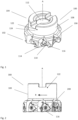
- Figure 1 schematically illustrates a toolholder (100) according to an embodiment of the invention.
- the toolholder being a milling cutter body for use in a milling process.
- the toolholder (100) comprising:
- FIG 2 schematically illustrates a cutting tool (300) according to an embodiment of the invention.
- the cutting tool (300) comprises the milling cutter body (100) illustrated in figure 1 and a plurality of cutting inserts (200) mounted in the insert pockets (110).
- the cutting tool (300) is configured to rotate in the direction R when used in the milling process.
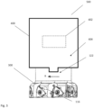
- FIG 3 schematically illustrates a cutting tool assembly (500) according to an embodiment of the invention.
- the cutting tool assembly (500) comprises the cutting tool (300) illustrated in figure 2 and a connecting tool unit (400) in form of a CNC-machine.
- the cutting tool (300) being coupled to the CNC-machine (400) via the coupling interface (112).
- the CNC-machine (400) comprises a machine control unit (402) being arranged to control the operation of the CNC-machine (400).
- the machine control unit (402) is operatively connected to a machine communication device (404).
- the machine communication device (404) is configured to receive the information transmitted from the communication device (122) and the machine control unit (402) is configured to control the operation of the CNC-machine (400) based on the information received from the communication device (122).
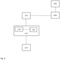
- FIG 4 schematically illustrates the communication within the cutting tool assembly illustrated in figure 3 .
- the control unit (116) comprises a crossbar array (118) of resistive memory devices and a power source (120) operatively connected to the crossbar array (118).
- the control unit (116) is operatively connected to the sensor (114) configured for detecting an environmental condition.
- the crossbar array (118) comprises a neural network stored thereon, wherein the neural network is adapted to determine a condition of the cutting insert (200) or of the milling process based on the environmental condition detected by the sensor (114).
- the power source (120) is arranged to provide the neural network stored on the crossbar array (118) with enough power for determining the condition of the cutting insert (200) or of the milling process.
- the control unit (116) is further operatively connected to the communication device (122), which is configured to transmit information from the control unit (116), wherein the information comprises information regarding the determined condition of the cutting insert (200) or of the milling process.
- the information transmitted from the communication device (122) is received by the machine communication device (404), which is operatively connected to the machine control unit (402).
- the machine control unit (402) is configured to control the operation of the CNC-machine (400) based on the information received from the communication device (122).
Landscapes
- Engineering & Computer Science (AREA)
- Mechanical Engineering (AREA)
- Physics & Mathematics (AREA)
- General Physics & Mathematics (AREA)
- Automation & Control Theory (AREA)
- Human Computer Interaction (AREA)
- Manufacturing & Machinery (AREA)
- Cutting Tools, Boring Holders, And Turrets (AREA)
Abstract
Description
- The present invention relates to a toolholder, a cutting tool, and a cutting tool assembly.
- Within the cutting industry it is becoming more common to use so called smart toolholders which are equipped with different type of sensors for detecting environmental conditions in the cutting process such as vibrations or temperatures. These detected environmental conditions are then transmitted to an external control device where a tool condition such as tool failure, tool wear or other process anomalies are determined based on said detected environmental conditions. Neural networks have been proven successful for analyzing the detected environmental conditions and determining the tool condition. Such a solution is disclosed in e.g.
US 7,341,410 B2 . - A problem with this type of solution is that due to the hostile machining environment in which the toolholder is provided when used in operation, the shuttling of data between the sensors and the external control device give rise to a significant amount of noise in the sensor signals which reduces the quality of the determination of the tool condition.
- It is an object of the present invention to overcome, or at least partially overcome, said problem by introducing a toolholder, a cutting tool, and a cutting tool assembly.
- The object of the present invention is achieved by means of a toolholder for use with a cutting element in a cutting process, wherein the toolholder comprising:
- a front end;
- a rear end; and
- a longitudinal axis A extending from the front end to the rear end,
- wherein the toolholder further comprising:
- a cutting portion at the front end; and
- a mounting portion at the rear end; wherein
- the cutting portion comprises at least one cutting element interface for receiving a cutting element, and wherein the mounting portion comprises a coupling interface adapted to be coupled to a connecting tool unit; wherein
- the toolholder further comprises at least one sensor for detecting an environmental condition; wherein
- the toolholder comprises a control unit operatively connected to the at least one sensor, wherein the control unit comprises:
- a crossbar array of resistive memory devices, and
- a power source operatively connected to the crossbar array, wherein the crossbar array comprises a neural network stored thereon, and wherein the neural network is adapted to determine a condition of the cutting element or of the cutting process based on the environmental condition detected by the at least one sensor.
- wherein the toolholder further comprising:
- The use of a crossbar array of resistive memory devices as an alternative to conventional central processing units (CPUs) in neural networks has become more interesting during the last years due to their significantly lower power consumption. Resistive memory devices are commonly also known as memristors. Such a crossbar array of resistive memory devices is described in e.g.
US 10,812,083 B2 - Due to their lower power consumption, the use of a crossbar array of resistive memory devices makes it possible to arrange the neural network within the toolholder, which is not the case with conventional CPUs since it is not possible to provide the amount of power needed to run this type of conventional CPU into the toolholder during operation.
- By arranging the neural network within the toolholder, the need of shuttling data between the sensor and the external control device is eliminated and the determination of the condition of the cutting element or of the cutting process can be made within the toolholder. Thereby, a source of significant noise in the sensor signal is eliminated and the signal quality is improved. By having an improved signal quality, the quality of the determination of the condition of the cutting element or of the cutting process is improved.
- The cutting element could be e.g. a cutting insert or a drill bit configured to be mounted in the toolholder.
- The cutting process could be e.g. a milling process, a turning, process, a drilling process, or a boring process. The cutting process is preferably a metal cutting process.
- The at least one cutting element interface could be e.g. an insert pocket configured to receive a cutting insert.
- The environmental condition could be e.g. vibrations, temperatures, forces or sound levels.
- The crossbar array of resistive memory devices is to be understood as a plurality of resistive memory devices connected to each other in rows and columns.
- The power source is arranged to provide the neural network stored on the crossbar array with enough power for determining the condition of the cutting element or of the cutting process. Preferably, the power source is further arranged to provide the at least one sensor with enough power for detecting the environmental condition. The power source could be e.g. a battery or a generator configured to convert kinetic energy in the toolholder into electrical energy.
- The neural network is adapted to determine the condition of the cutting element or of the cutting process by being pre-trained before being implemented at the crossbar array. The pre-training is preferably made outside of the toolholder. The neural network may continuously learn and update itself with obtained environmental data. Alternatively, the neural network is pre-trained based on input from an operator.
- The condition of the cutting element could be e.g. tool wear or tool failure. The condition of the cutting process could be e.g. a non-recommended set-up of cutting data parameters, e.g. feed rate, cutting speed or cutting depth; or other process anomalies such as lack of an expected environmental condition from the at least one sensor, e.g. that no input is given from the sensor to the neural network, which could indicate a malfunction of the sensor.
- According to an embodiment, the toolholder further comprises a communication device operatively connected to the control unit, wherein the communication device is configured to transmit information from the control unit, wherein the information comprises information regarding the determined condition of the cutting element or of the cutting process.
- By providing a communication device operatively connected to the control unit, the determined condition of the cutting element or of the cutting process can be transmitted to external devices, such as computer numerical control (CNC) machines or external computers, during operation of the toolholder. By only transmitting information regarding the determined condition of the cutting element or of the cutting process, the amount of data transmitted outside of the toolholder is significantly reduced compared to the prior art systems where the detected environmental conditions from the at least one sensor need to be constantly transmitted. This is particularly useful in the case where the toolholder is provided with a plurality of sensors since the amount of data to be transmitted outside of the toolholder becomes just a fraction compared to the amount of data generated by the plurality of sensors. Further, since the determination of the cutting element or of the cutting process already has been made when the information is transmitted outside of the toolholder, the impact of the added noise is less severe for the further usage of the determined condition of the cutting element or of the cutting process. Also, the energy consumption of the communication device is reduced. Further, by sending processed data in the form of the determined condition of the cutting element or of the cutting process, the amount of data can be controlled in a way which is not possible when sending all data gathered by the sensors. For example, in some embodiments, the determined condition of the cutting element or of the cutting process may be a binary piece of information indicating whether the tool can be used or not, which can be sent using a very small amount of data.
- Preferably, the power source is further configured to provide the communication device with enough power to transmit the information from the control unit.
- According to an embodiment, the neural network is adapted to determine if the determined condition of the cutting element or of the cutting process fulfil at least one pre-determined condition, and wherein the communication device is configured to transmit the information from the control unit only if the at least one pre-determined condition is fulfilled.
- By only transmitting the information from the control unit when a pre-determined condition is fulfilled, the amount of data transmitted outside of the toolholder is even further reduced. For example, in the case of the determined condition of the cutting element or of the cutting process is an amount of wear of the cutting element, the pre-determined condition could be a threshold value indicating when the wear of the cutting element will have a significant impact on the quality of the cutting process.
- According to an embodiment, the communication device is a radio frequency transmitter or an infrared frequency transmitter.
- By using a radio frequency transmitter or an infrared frequency transmitter the impact from the hostile environment surrounding the toolholder during operation to the transmitted signal is kept to a minimum since the signal transmitted from these types of transmitters is less sensitive to the noise generated by the hostile environment. Further, these types of transmitters can be made very small which will reduce the energy consumption of the transmitter. These types of transmitters are suitable for use in the toolholder since the amount of data transmitted outside the toolholder is significantly reduced as compared to the prior art systems, as described above.
- According to an embodiment, the toolholder comprises an outer circumferential surface extending from the front end to the rear end, and wherein the communication device is arranged at the outer circumferential surface.
- By arranging the communication device at the outer circumferential surface, interferences from the toolholder, which is usually made of metal, to the transmitted signal is reduced.
- According to an embodiment, the communication device is arranged at the mounting portion.
- By arranging the communication device at the mounting portion, the communication device will be placed away from the cutting portion where the environment surrounding the toolholder during operation is as most hostile. Thereby, the amount of noise added to the transmitted signal is reduced. Also, the risk of damaging the communication device is reduced since it is placed away from the cutting portion where the environment surrounding the toolholder during operation is as most hostile.
- According to an embodiment, the toolholder comprises a plurality of sensors, wherein the plurality of sensors is configured to detect a plurality of environmental conditions.
- By providing the toolholder with a plurality of sensors, the determination of the condition of the cutting element or of the cutting process is further improved since the amount of input to the neural network is increased.
- Preferably, the plurality of environmental conditions are different types of environmental conditions. The plurality of sensors could be configured to detect e.g. vibrations, temperatures and sound levels, which combined give an improved indication of the cutting conditions at the cutting element.
- According to an embodiment, the plurality of environmental conditions is the same type of environmental condition, e.g. vibrations, detected at different positions at the toolholder.
- By detecting the same type of environmental condition at different positions at the toolholder, cutting process conditions such as an uneven amount of wear of the cutting elements, can be determined.
- According to an embodiment, the at least one sensor being at least any of an accelerometer, a thermo couple, a piezo electric force sensor, a strain gauge or an acoustic sensor.
- According to an embodiment, the condition of the cutting element or of the cutting process is at least any of wear or failure of the cutting element.
- By determining wear or failure of the cutting element, the cutting process can be significantly improved since these conditions have a high impact on the cutting process.
- According to an embodiment, the at least one sensor is arranged in the cutting portion.
- By arranging the at least one sensor in the cutting portion, the distance between the sensor and the cutting element becomes short, which makes the detected environmental condition more representative of the cutting condition at the cutting element.
- According to an embodiment, the at least one sensor is arranged in the cutting element interface.
- By arranging the at least one sensor in the cutting element interface, the sensor is arranged as close as possible to the cutting element, which makes the detected environmental condition more representative of the cutting condition at the cutting element.
- According to an embodiment, the control unit is arranged in the cutting portion.
- By arranging the control unit in the cutting portion, the distance between the at least one sensor and the control unit becomes even shorter, which will further reduce the amount of noise in the sensor signal.
- According to an embodiment, the control unit is arranged at the coupling interface.
- By arranging the control unit at the coupling interface, the control unit will become unexposed to the hostile environment surrounding the toolholder during operation when the toolholder being coupled to the control unit. The control unit thereby becomes protected from being damaged. Further, the implementation of the control unit in the toolholder is facilitated. The coupling interface could be e.g. a female coupling interface configured to be coupled to a male coupling interface at the connecting tool unit. Of course, the coupling interface could also be a male interface configured to be coupled to a female coupling interface at the connecting tool unit, or any other well-known type of coupling interfaces.
- According to an embodiment, the toolholder is adapted to be rotated during use in the cutting process, and wherein the power source is adapted to convert kinetic energy resulting from the rotation of the toolholder into electrical energy. According to an embodiment, the power source comprises a generator configured to generate electrical current, wherein the generator is attached to the toolholder. The toolholder further comprises a free rotating disk mounted in the toolholder. The free rotating disk is connected via an axel to the generator. During acceleration and deacceleration of the tool holder the disk and tool holder will have a relative rotational movement. This relative movement is harvested via the generator as electrical current.
- By adapting the power source to convert kinetic energy resulting from the rotation of the toolholder into electrical energy, a stable power supply is provided since there is no need of providing any additional electrical energy into the toolholder during operation. Additionally, a more energy efficient system is provided since the energy already generated when using the toolholder in the cutting process is used to also provide the neural network with the energy needed to determine the condition of the cutting element or of the cutting process. Due to the significantly lower energy consumption of the crossbar array, the electric energy being able to be generated from the rotation of the toolholder is enough to provide the neural network with enough power for determining the condition of the cutting element or of the cutting process.
- According to an embodiment the power source comprises a generator configured to generate electrical current. The toolholder further comprises at least one coolant channel configured to deliver coolant fluid towards the cutting portion. The coolant channel comprises an impeller which is connected to the generator via an axel. The flow of coolant fluid will pass the impeller and cause a rotational movement of the impeller. The rotational movement of the impeller is harvested as electrical energy by the generator.
- By arranging the power source as an energy harvesting device configured to harvest energy from the flow of coolant fluid, energy harvesting can be made also for non-rotational toolholders.
- The object of the present invention is further achieved by means of a cutting tool comprising a toolholder as disclosed above and a cutting element, wherein the cutting element is mounted in the cutting element interface.
- According to an embodiment, the cutting element interface being an insert pocket, and wherein the cutting element being a cutting insert.
- According to an embodiment, the cutting insert is a cubic boron nitride (CBN) cutting insert, a cemented carbide cutting insert, a cermet cutting insert, or a ceramic cutting insert.
- The object of the present invention is further achieved by means of a cutting tool assembly comprising a cutting tool as disclosed above, and a connecting tool unit, wherein the cutting tool is coupled to the connecting tool unit via the coupling interface. The coupling interface could be e.g. a female coupling interface configured to be coupled to a male coupling interface at the connecting tool unit.
- According to an embodiment, the connecting tool unit being a CNC-machine, wherein the CNC-machine comprises a machine control unit, wherein the machine control unit is arranged to control the CNC-machine, and wherein the machine control unit is operatively connected to a machine communication device, wherein the machine communication device is configured to receive the information transmitted from the communication device, and wherein the machine control unit is configured to control the operation of the CNC-machine based on the information received from the communication unit.
- By arranging the connecting tool unit as a CNC-machine as described above, it is possible to adjust the operation of the CNC-machine in response to the condition of the cutting element or of the cutting process determined by the control unit. The cutting process can then be adjusted in real time dependent on the determined condition and the cutting process can thereby be improved.
- According to an embodiment, the machine communication device is a radio frequency receiver or an infrared frequency receiver.
-
-
Figure 1 schematically illustrates a toolholder according to an embodiment of the invention. -
Figure 2 schematically illustrates a cutting tool according to an embodiment of the invention. -
Figure 3 schematically illustrates a cutting tool assembly according to an embodiment of the invention. -
Figure 4 schematically illustrates the communication within the cutting tool assembly illustrated infigure 3 . - The disclosed embodiments will now be described more fully hereinafter with reference to the accompanying drawings, in which certain embodiments of the invention are shown. This invention may, however, be embodied in many different forms and should not be construed as limited to the embodiments set forth herein; rather, these embodiments are provided by way of example so that the disclosure will be thorough and complete, and will fully convey the scope of the invention to those skilled in the art. Like reference numbers refer to like elements throughout. The elements illustrated in the drawings are not necessary according to scale. Some elements might have been enlarged in order to clearly illustrate those elements.
-
Figure 1 schematically illustrates a toolholder (100) according to an embodiment of the invention. The toolholder being a milling cutter body for use in a milling process. The toolholder (100) comprising: - a front end (102);
- a rear end (104); and
- a longitudinal axis A extending from the front end (102) to the rear end (104),
- wherein the toolholder (100) further comprising:
- a cutting portion (106) at the front end (102); and
- a mounting portion (108) at the rear end (104); wherein
- the cutting portion (106) comprises a plurality of insert pockets (110) for receiving cutting elements (200) in form of cutting inserts, and wherein the mounting portion (108) comprises a coupling interface (112) adapted to be coupled to a connecting tool unit (400). The coupling interface (112) being a female coupling interface adapted to be coupled to a male coupling interface at the connecting tool unit (400). The toolholder (100) further comprises a sensor (114) arranged in the insert pocket (110) for detecting an environmental condition. The toolholder (100) further comprises a control unit (116) arranged in the cutting part (106). The control unit (116) comprises a crossbar array (118) of resistive memory devices and a power source (120) operatively connected to the crossbar array (118), c.f.
figure 4 . The crossbar array (118) comprises a neural network stored thereon. The neural network is adapted to determine a condition of the cutting inserts (200) or of the milling process based on the environmental condition detected by the sensor (114). The toolholder (100) further comprises an outer circumferential surface (124) extending from the front end (102) to the rear end (104). The toolholder (100) comprises a communication device (122) arranged at the circumferential surface (124). The communication device (122) is configured to transmit information from the control unit (116), wherein the information comprises information regarding the determined condition of the cutting insert (200) or of the milling process.
- wherein the toolholder (100) further comprising:
-
Figure 2 schematically illustrates a cutting tool (300) according to an embodiment of the invention. The cutting tool (300) comprises the milling cutter body (100) illustrated infigure 1 and a plurality of cutting inserts (200) mounted in the insert pockets (110). The cutting tool (300) is configured to rotate in the direction R when used in the milling process. -
Figure 3 schematically illustrates a cutting tool assembly (500) according to an embodiment of the invention. The cutting tool assembly (500) comprises the cutting tool (300) illustrated infigure 2 and a connecting tool unit (400) in form of a CNC-machine. The cutting tool (300) being coupled to the CNC-machine (400) via the coupling interface (112). The CNC-machine (400) comprises a machine control unit (402) being arranged to control the operation of the CNC-machine (400). The machine control unit (402) is operatively connected to a machine communication device (404). The machine communication device (404) is configured to receive the information transmitted from the communication device (122) and the machine control unit (402) is configured to control the operation of the CNC-machine (400) based on the information received from the communication device (122). -
Figure 4 schematically illustrates the communication within the cutting tool assembly illustrated infigure 3 . The control unit (116) comprises a crossbar array (118) of resistive memory devices and a power source (120) operatively connected to the crossbar array (118). The control unit (116) is operatively connected to the sensor (114) configured for detecting an environmental condition. The crossbar array (118) comprises a neural network stored thereon, wherein the neural network is adapted to determine a condition of the cutting insert (200) or of the milling process based on the environmental condition detected by the sensor (114). The power source (120) is arranged to provide the neural network stored on the crossbar array (118) with enough power for determining the condition of the cutting insert (200) or of the milling process. The control unit (116) is further operatively connected to the communication device (122), which is configured to transmit information from the control unit (116), wherein the information comprises information regarding the determined condition of the cutting insert (200) or of the milling process. The information transmitted from the communication device (122) is received by the machine communication device (404), which is operatively connected to the machine control unit (402). The machine control unit (402) is configured to control the operation of the CNC-machine (400) based on the information received from the communication device (122).
Claims (15)
- Toolholder (100) for use with a cutting element (200) in a cutting process, wherein the toolholder (100) comprising:- a front end (102);- a rear end (104); and- a longitudinal axis A extending from the front end (102) to the rear end (104),wherein the toolholder (100) further comprising:- a cutting portion (106) at the front end (102); and- a mounting portion (108) at the rear end (104); whereinthe cutting portion (106) comprises at least one cutting element interface (110) for receiving a cutting element (200) and wherein the mounting portion (108) comprises a coupling interface (112) adapted to be coupled to a connecting tool unit (400); whereinthe toolholder (100) further comprises at least one sensor (114) for detecting an environmental condition;characterized in thatthe toolholder (100) comprises a control unit (116) operatively connected to the at least one sensor (114), wherein the control unit (116) comprises:- a crossbar array (118) of resistive memory devices, and- a power source (120) operatively connected to the crossbar array (118), whereinthe crossbar array (118) comprises a neural network stored thereon, and wherein the neural network is adapted to determine a condition of the cutting element (200) or of the cutting process based on the environmental condition detected by the at least one sensor (114).
- The toolholder (100) according to claim 1, wherein the toolholder (100) further comprises a communication device (122) operatively connected to the control unit (116), wherein the communication device (122) is configured to transmit information from the control unit (116), wherein the information comprises information regarding the determined condition of the cutting element (200) or of the cutting process.
- The toolholder (100) according to claim 2, wherein the neural network is adapted to determine if the determined condition of the cutting element (200) or of the cutting process fulfil at least one pre-determined condition, and wherein the communication device (122) is configured to transmit the information from the control unit (116) only if the at least one pre-determined condition is fulfilled.
- The toolholder (100) according to claim 2 or 3, wherein the communication device (122) is a radio frequency transmitter or an infrared frequency transmitter.
- The toolholder (100) according to any of claims 2-4, wherein the toolholder (100) comprises an outer circumferential surface (124) extending from the front end (102) to the rear end (104), and wherein the communication device (122) is arranged at the outer circumferential surface (124).
- The toolholder (100) according to any of claims 2-5, wherein the communication device (122) is arranged at the mounting portion (108).
- The toolholder (100) according to any of the preceding claims, wherein the toolholder (100) comprises a plurality of sensors (114), wherein the plurality of sensors (114) is configured to detect a plurality of environmental conditions.
- The toolholder (100) according to any of the preceding claims, wherein the at least one sensor (114) is arranged in the cutting portion (106).
- The toolholder (100) according to claim 8, wherein the at least one sensor (104) is arranged in the cutting element interface (110).
- The toolholder (100) according to claim 8 or 9, wherein the control unit (116) is arranged in the cutting portion (106).
- The toolholder (100) according to any of claims 1-9, wherein the control unit (116) is arranged at the coupling interface (112).
- The toolholder (100) according to any of the preceding claims, wherein the toolholder (100) is adapted to be rotated during use in the cutting process, and wherein the power source (120) is adapted to convert kinetic energy resulting from the rotation of the toolholder (100) into electrical energy.
- A cutting tool (300) comprising:- a toolholder (100) according to any of claims 1-12; and- a cutting element (200), whereinthe cutting element is mounted in the cutting element interface (110).
- A cutting tool assembly (500) comprising:- a cutting tool (300) according to claim 13; and- a connecting tool unit (400), whereinthe cutting tool (300) is coupled to the connecting tool unit (400) via the coupling interface (112).
- The cutting tool assembly (500) according to claim 14, wherein the connecting tool unit (400) being a computer numerical control machine, wherein the computer numerical control machine (400) comprises a machine control unit (402), wherein the machine control unit (402) is arranged to control the computer numerical control machine (400), and wherein the machine control unit (402) is operatively connected to a machine communication device (404), wherein the machine communication device (404) is configured to receive the information transmitted from the communication device (122), and wherein the machine control unit (402) is configured to control the operation of the computer numerical control machine (400) based on the information received from the communication device (122).
Priority Applications (3)
| Application Number | Priority Date | Filing Date | Title |
|---|---|---|---|
| EP22181406.4A EP4299244B1 (en) | 2022-06-28 | 2022-06-28 | Toolholder, cutting tool, and cutting tool assembly |
| PCT/EP2023/064335 WO2024002602A1 (en) | 2022-06-28 | 2023-05-29 | Toolholder, cutting tool, and cutting tool assembly |
| US18/871,883 US20250353086A1 (en) | 2022-06-28 | 2023-05-29 | Toolholder, cutting tool, and cutting tool assembly |
Applications Claiming Priority (1)
| Application Number | Priority Date | Filing Date | Title |
|---|---|---|---|
| EP22181406.4A EP4299244B1 (en) | 2022-06-28 | 2022-06-28 | Toolholder, cutting tool, and cutting tool assembly |
Publications (2)
| Publication Number | Publication Date |
|---|---|
| EP4299244A1 true EP4299244A1 (en) | 2024-01-03 |
| EP4299244B1 EP4299244B1 (en) | 2025-04-02 |
Family
ID=82399341
Family Applications (1)
| Application Number | Title | Priority Date | Filing Date |
|---|---|---|---|
| EP22181406.4A Active EP4299244B1 (en) | 2022-06-28 | 2022-06-28 | Toolholder, cutting tool, and cutting tool assembly |
Country Status (3)
| Country | Link |
|---|---|
| US (1) | US20250353086A1 (en) |
| EP (1) | EP4299244B1 (en) |
| WO (1) | WO2024002602A1 (en) |
Citations (3)
| Publication number | Priority date | Publication date | Assignee | Title |
|---|---|---|---|---|
| US7341410B2 (en) | 2003-03-10 | 2008-03-11 | Foster-Miller, Inc. | Dynamical instrument for machining |
| US20090234490A1 (en) * | 2008-03-17 | 2009-09-17 | Suprock Christopher A | Smart Machining System and Smart Tool Holder Therefor |
| US10812083B2 (en) | 2017-04-24 | 2020-10-20 | The Regents Of The University Of Michigan | Techniques for computing dot products with memory devices |
-
2022
- 2022-06-28 EP EP22181406.4A patent/EP4299244B1/en active Active
-
2023
- 2023-05-29 WO PCT/EP2023/064335 patent/WO2024002602A1/en not_active Ceased
- 2023-05-29 US US18/871,883 patent/US20250353086A1/en active Pending
Patent Citations (3)
| Publication number | Priority date | Publication date | Assignee | Title |
|---|---|---|---|---|
| US7341410B2 (en) | 2003-03-10 | 2008-03-11 | Foster-Miller, Inc. | Dynamical instrument for machining |
| US20090234490A1 (en) * | 2008-03-17 | 2009-09-17 | Suprock Christopher A | Smart Machining System and Smart Tool Holder Therefor |
| US10812083B2 (en) | 2017-04-24 | 2020-10-20 | The Regents Of The University Of Michigan | Techniques for computing dot products with memory devices |
Also Published As
| Publication number | Publication date |
|---|---|
| WO2024002602A1 (en) | 2024-01-04 |
| US20250353086A1 (en) | 2025-11-20 |
| EP4299244B1 (en) | 2025-04-02 |
Similar Documents
| Publication | Publication Date | Title |
|---|---|---|
| US9498827B2 (en) | Arrangement for controlling the process of rotary chip removing machining of a workpiece, and a cutting tool for rotary chip removing machining | |
| CN113453827B (en) | Tool holder, cutting tool, cutting workpiece manufacturing method and data collection method | |
| EP2222436B1 (en) | Cutting tool with integrated circuit chip | |
| US8080918B2 (en) | Apparatus and method for controlling the machining of workpieces using piezoceramic transducers | |
| JP6975143B2 (en) | Tool holder with built-in sensor | |
| EP0708872B1 (en) | Method and apparatus for controlling the head of a drilling or core-drilling device | |
| CN109564425A (en) | Diagnostic device, facility for study and diagnostic system | |
| US20100186560A1 (en) | Apparatus and method for controlling the machining of workpieces using piezoceramic transducers | |
| CN102015203A (en) | Intelligent Machining System and Its Intelligent Tool Fixture | |
| JP6931150B2 (en) | Temperature measuring device | |
| EP4299244B1 (en) | Toolholder, cutting tool, and cutting tool assembly | |
| EP1083023B1 (en) | Numerical control apparatus for nc machine tool | |
| CN109826566B (en) | Carbide coreless drill | |
| NO326201B1 (en) | Rock drilling device including a carrier, and rock crushing machine movable when used relative to the carrier of a rock drilling device | |
| JP5356816B2 (en) | Tool condition monitoring system | |
| NZ216153A (en) | Monitoring grinding mill charge level by position of impact sound | |
| CN220226867U (en) | Cutter detection system and heading machine | |
| TWI812107B (en) | Tool holder sensor configuration | |
| KR101827394B1 (en) | Wireless Monitoring Device of Cutting Resistance at the Tip of the Rotary Tool | |
| WO2011021963A1 (en) | Device for drilling or boring openings | |
| US20080189448A1 (en) | Method for implementing a control channel in a system of circumvention and recovery | |
| JP2008000828A (en) | Nc lathe and tool condition detecting method for cutting tool in nc lathe | |
| Schörghofer et al. | Chatter detection and avoidance using a sensory tool holder | |
| WO2017082511A1 (en) | Apparatus for wirelessly monitoring cutting force of rotating tool | |
| CN121821142A (en) | Automatic identification and detection knife handle for cutting force |
Legal Events
| Date | Code | Title | Description |
|---|---|---|---|
| PUAI | Public reference made under article 153(3) epc to a published international application that has entered the european phase |
Free format text: ORIGINAL CODE: 0009012 |
|
| STAA | Information on the status of an ep patent application or granted ep patent |
Free format text: STATUS: THE APPLICATION HAS BEEN PUBLISHED |
|
| AK | Designated contracting states |
Kind code of ref document: A1 Designated state(s): AL AT BE BG CH CY CZ DE DK EE ES FI FR GB GR HR HU IE IS IT LI LT LU LV MC MK MT NL NO PL PT RO RS SE SI SK SM TR |
|
| STAA | Information on the status of an ep patent application or granted ep patent |
Free format text: STATUS: REQUEST FOR EXAMINATION WAS MADE |
|
| 17P | Request for examination filed |
Effective date: 20240703 |
|
| RBV | Designated contracting states (corrected) |
Designated state(s): AL AT BE BG CH CY CZ DE DK EE ES FI FR GB GR HR HU IE IS IT LI LT LU LV MC MK MT NL NO PL PT RO RS SE SI SK SM TR |
|
| GRAP | Despatch of communication of intention to grant a patent |
Free format text: ORIGINAL CODE: EPIDOSNIGR1 |
|
| STAA | Information on the status of an ep patent application or granted ep patent |
Free format text: STATUS: GRANT OF PATENT IS INTENDED |
|
| RIC1 | Information provided on ipc code assigned before grant |
Ipc: G05B 23/02 20060101ALI20241022BHEP Ipc: G05B 19/406 20060101ALI20241022BHEP Ipc: B23Q 17/09 20060101AFI20241022BHEP |
|
| INTG | Intention to grant announced |
Effective date: 20241030 |
|
| GRAS | Grant fee paid |
Free format text: ORIGINAL CODE: EPIDOSNIGR3 |
|
| GRAA | (expected) grant |
Free format text: ORIGINAL CODE: 0009210 |
|
| STAA | Information on the status of an ep patent application or granted ep patent |
Free format text: STATUS: THE PATENT HAS BEEN GRANTED |
|
| AK | Designated contracting states |
Kind code of ref document: B1 Designated state(s): AL AT BE BG CH CY CZ DE DK EE ES FI FR GB GR HR HU IE IS IT LI LT LU LV MC MK MT NL NO PL PT RO RS SE SI SK SM TR |
|
| REG | Reference to a national code |
Ref country code: GB Ref legal event code: FG4D |
|
| REG | Reference to a national code |
Ref country code: CH Ref legal event code: EP |
|
| REG | Reference to a national code |
Ref country code: IE Ref legal event code: FG4D |
|
| REG | Reference to a national code |
Ref country code: DE Ref legal event code: R096 Ref document number: 602022012472 Country of ref document: DE |
|
| P01 | Opt-out of the competence of the unified patent court (upc) registered |
Free format text: CASE NUMBER: APP_14111/2025 Effective date: 20250321 |
|
| PGFP | Annual fee paid to national office [announced via postgrant information from national office to epo] |
Ref country code: AT Payment date: 20250721 Year of fee payment: 4 |
|
| REG | Reference to a national code |
Ref country code: NL Ref legal event code: MP Effective date: 20250402 |
|
| PG25 | Lapsed in a contracting state [announced via postgrant information from national office to epo] |
Ref country code: NL Free format text: LAPSE BECAUSE OF FAILURE TO SUBMIT A TRANSLATION OF THE DESCRIPTION OR TO PAY THE FEE WITHIN THE PRESCRIBED TIME-LIMIT Effective date: 20250402 |
|
| REG | Reference to a national code |
Ref country code: AT Ref legal event code: MK05 Ref document number: 1780836 Country of ref document: AT Kind code of ref document: T Effective date: 20250402 |
|
| PG25 | Lapsed in a contracting state [announced via postgrant information from national office to epo] |
Ref country code: FI Free format text: LAPSE BECAUSE OF FAILURE TO SUBMIT A TRANSLATION OF THE DESCRIPTION OR TO PAY THE FEE WITHIN THE PRESCRIBED TIME-LIMIT Effective date: 20250402 Ref country code: ES Free format text: LAPSE BECAUSE OF FAILURE TO SUBMIT A TRANSLATION OF THE DESCRIPTION OR TO PAY THE FEE WITHIN THE PRESCRIBED TIME-LIMIT Effective date: 20250402 Ref country code: PT Free format text: LAPSE BECAUSE OF FAILURE TO SUBMIT A TRANSLATION OF THE DESCRIPTION OR TO PAY THE FEE WITHIN THE PRESCRIBED TIME-LIMIT Effective date: 20250804 |
|
| REG | Reference to a national code |
Ref country code: LT Ref legal event code: MG9D |
|
| PG25 | Lapsed in a contracting state [announced via postgrant information from national office to epo] |
Ref country code: NO Free format text: LAPSE BECAUSE OF FAILURE TO SUBMIT A TRANSLATION OF THE DESCRIPTION OR TO PAY THE FEE WITHIN THE PRESCRIBED TIME-LIMIT Effective date: 20250702 Ref country code: GR Free format text: LAPSE BECAUSE OF FAILURE TO SUBMIT A TRANSLATION OF THE DESCRIPTION OR TO PAY THE FEE WITHIN THE PRESCRIBED TIME-LIMIT Effective date: 20250703 |
|
| PG25 | Lapsed in a contracting state [announced via postgrant information from national office to epo] |
Ref country code: PL Free format text: LAPSE BECAUSE OF FAILURE TO SUBMIT A TRANSLATION OF THE DESCRIPTION OR TO PAY THE FEE WITHIN THE PRESCRIBED TIME-LIMIT Effective date: 20250402 |
|
| PG25 | Lapsed in a contracting state [announced via postgrant information from national office to epo] |
Ref country code: BG Free format text: LAPSE BECAUSE OF FAILURE TO SUBMIT A TRANSLATION OF THE DESCRIPTION OR TO PAY THE FEE WITHIN THE PRESCRIBED TIME-LIMIT Effective date: 20250402 |
|
| PG25 | Lapsed in a contracting state [announced via postgrant information from national office to epo] |
Ref country code: AT Free format text: LAPSE BECAUSE OF FAILURE TO SUBMIT A TRANSLATION OF THE DESCRIPTION OR TO PAY THE FEE WITHIN THE PRESCRIBED TIME-LIMIT Effective date: 20250402 Ref country code: HR Free format text: LAPSE BECAUSE OF FAILURE TO SUBMIT A TRANSLATION OF THE DESCRIPTION OR TO PAY THE FEE WITHIN THE PRESCRIBED TIME-LIMIT Effective date: 20250402 |
|
| PG25 | Lapsed in a contracting state [announced via postgrant information from national office to epo] |
Ref country code: RS Free format text: LAPSE BECAUSE OF FAILURE TO SUBMIT A TRANSLATION OF THE DESCRIPTION OR TO PAY THE FEE WITHIN THE PRESCRIBED TIME-LIMIT Effective date: 20250702 |
|
| PG25 | Lapsed in a contracting state [announced via postgrant information from national office to epo] |
Ref country code: IS Free format text: LAPSE BECAUSE OF FAILURE TO SUBMIT A TRANSLATION OF THE DESCRIPTION OR TO PAY THE FEE WITHIN THE PRESCRIBED TIME-LIMIT Effective date: 20250802 |
|
| PG25 | Lapsed in a contracting state [announced via postgrant information from national office to epo] |
Ref country code: LV Free format text: LAPSE BECAUSE OF FAILURE TO SUBMIT A TRANSLATION OF THE DESCRIPTION OR TO PAY THE FEE WITHIN THE PRESCRIBED TIME-LIMIT Effective date: 20250402 |
|
| REG | Reference to a national code |
Ref country code: DE Ref legal event code: R097 Ref document number: 602022012472 Country of ref document: DE |
|
| PG25 | Lapsed in a contracting state [announced via postgrant information from national office to epo] |
Ref country code: SM Free format text: LAPSE BECAUSE OF FAILURE TO SUBMIT A TRANSLATION OF THE DESCRIPTION OR TO PAY THE FEE WITHIN THE PRESCRIBED TIME-LIMIT Effective date: 20250402 Ref country code: DK Free format text: LAPSE BECAUSE OF FAILURE TO SUBMIT A TRANSLATION OF THE DESCRIPTION OR TO PAY THE FEE WITHIN THE PRESCRIBED TIME-LIMIT Effective date: 20250402 |
|
| PG25 | Lapsed in a contracting state [announced via postgrant information from national office to epo] |
Ref country code: CZ Free format text: LAPSE BECAUSE OF FAILURE TO SUBMIT A TRANSLATION OF THE DESCRIPTION OR TO PAY THE FEE WITHIN THE PRESCRIBED TIME-LIMIT Effective date: 20250402 |
|
| PG25 | Lapsed in a contracting state [announced via postgrant information from national office to epo] |
Ref country code: EE Free format text: LAPSE BECAUSE OF FAILURE TO SUBMIT A TRANSLATION OF THE DESCRIPTION OR TO PAY THE FEE WITHIN THE PRESCRIBED TIME-LIMIT Effective date: 20250402 |
|
| PG25 | Lapsed in a contracting state [announced via postgrant information from national office to epo] |
Ref country code: SK Free format text: LAPSE BECAUSE OF FAILURE TO SUBMIT A TRANSLATION OF THE DESCRIPTION OR TO PAY THE FEE WITHIN THE PRESCRIBED TIME-LIMIT Effective date: 20250402 |
|
| REG | Reference to a national code |
Ref country code: CH Ref legal event code: H13 Free format text: ST27 STATUS EVENT CODE: U-0-0-H10-H13 (AS PROVIDED BY THE NATIONAL OFFICE) Effective date: 20260127 |
|
| PG25 | Lapsed in a contracting state [announced via postgrant information from national office to epo] |
Ref country code: MC Free format text: LAPSE BECAUSE OF FAILURE TO SUBMIT A TRANSLATION OF THE DESCRIPTION OR TO PAY THE FEE WITHIN THE PRESCRIBED TIME-LIMIT Effective date: 20250402 |
|
| PLBE | No opposition filed within time limit |
Free format text: ORIGINAL CODE: 0009261 |
|
| STAA | Information on the status of an ep patent application or granted ep patent |
Free format text: STATUS: NO OPPOSITION FILED WITHIN TIME LIMIT |
|
| REG | Reference to a national code |
Ref country code: CH Ref legal event code: L10 Free format text: ST27 STATUS EVENT CODE: U-0-0-L10-L00 (AS PROVIDED BY THE NATIONAL OFFICE) Effective date: 20260211 |
|
| PG25 | Lapsed in a contracting state [announced via postgrant information from national office to epo] |
Ref country code: LU Free format text: LAPSE BECAUSE OF NON-PAYMENT OF DUE FEES Effective date: 20250628 |
|
| REG | Reference to a national code |
Ref country code: BE Ref legal event code: MM Effective date: 20250630 |
|
| PG25 | Lapsed in a contracting state [announced via postgrant information from national office to epo] |
Ref country code: RO Free format text: LAPSE BECAUSE OF FAILURE TO SUBMIT A TRANSLATION OF THE DESCRIPTION OR TO PAY THE FEE WITHIN THE PRESCRIBED TIME-LIMIT Effective date: 20250402 |
|
| 26N | No opposition filed |
Effective date: 20260105 |
|
| PG25 | Lapsed in a contracting state [announced via postgrant information from national office to epo] |
Ref country code: IE Free format text: LAPSE BECAUSE OF NON-PAYMENT OF DUE FEES Effective date: 20250628 |
|
| PG25 | Lapsed in a contracting state [announced via postgrant information from national office to epo] |
Ref country code: BE Free format text: LAPSE BECAUSE OF NON-PAYMENT OF DUE FEES Effective date: 20250630 |
|
| PG25 | Lapsed in a contracting state [announced via postgrant information from national office to epo] |
Ref country code: CH Free format text: LAPSE BECAUSE OF NON-PAYMENT OF DUE FEES Effective date: 20250630 |
|
| PG25 | Lapsed in a contracting state [announced via postgrant information from national office to epo] |
Ref country code: LT Free format text: LAPSE BECAUSE OF FAILURE TO SUBMIT A TRANSLATION OF THE DESCRIPTION OR TO PAY THE FEE WITHIN THE PRESCRIBED TIME-LIMIT Effective date: 20250402 |
|
| PGFP | Annual fee paid to national office [announced via postgrant information from national office to epo] |
Ref country code: GB Payment date: 20260511 Year of fee payment: 5 |
|
| PGFP | Annual fee paid to national office [announced via postgrant information from national office to epo] |
Ref country code: IT Payment date: 20260522 Year of fee payment: 5 |
|
| PGFP | Annual fee paid to national office [announced via postgrant information from national office to epo] |
Ref country code: DE Payment date: 20260506 Year of fee payment: 5 |
|
| PGFP | Annual fee paid to national office [announced via postgrant information from national office to epo] |
Ref country code: FR Payment date: 20260521 Year of fee payment: 5 |
|
| PG25 | Lapsed in a contracting state [announced via postgrant information from national office to epo] |
Ref country code: SE Free format text: LAPSE BECAUSE OF FAILURE TO SUBMIT A TRANSLATION OF THE DESCRIPTION OR TO PAY THE FEE WITHIN THE PRESCRIBED TIME-LIMIT Effective date: 20250402 Ref country code: CY Free format text: LAPSE BECAUSE OF FAILURE TO SUBMIT A TRANSLATION OF THE DESCRIPTION OR TO PAY THE FEE WITHIN THE PRESCRIBED TIME-LIMIT Effective date: 20250402 |