EP4299179A1 - Priming device and priming method for fluid cartridge, and fluid dispense device - Google Patents
Priming device and priming method for fluid cartridge, and fluid dispense device Download PDFInfo
- Publication number
- EP4299179A1 EP4299179A1 EP23176781.5A EP23176781A EP4299179A1 EP 4299179 A1 EP4299179 A1 EP 4299179A1 EP 23176781 A EP23176781 A EP 23176781A EP 4299179 A1 EP4299179 A1 EP 4299179A1
- Authority
- EP
- European Patent Office
- Prior art keywords
- fluid
- cartridge
- priming
- impact
- fluid cartridge
- Prior art date
- Legal status (The legal status is an assumption and is not a legal conclusion. Google has not performed a legal analysis and makes no representation as to the accuracy of the status listed.)
- Withdrawn
Links
Images





Classifications
-
- G—PHYSICS
- G01—MEASURING; TESTING
- G01N—INVESTIGATING OR ANALYSING MATERIALS BY DETERMINING THEIR CHEMICAL OR PHYSICAL PROPERTIES
- G01N1/00—Sampling; Preparing specimens for investigation
- G01N1/28—Preparing specimens for investigation including physical details of (bio-)chemical methods covered elsewhere, e.g. G01N33/50, C12Q
-
- B—PERFORMING OPERATIONS; TRANSPORTING
- B41—PRINTING; LINING MACHINES; TYPEWRITERS; STAMPS
- B41J—TYPEWRITERS; SELECTIVE PRINTING MECHANISMS, i.e. MECHANISMS PRINTING OTHERWISE THAN FROM A FORME; CORRECTION OF TYPOGRAPHICAL ERRORS
- B41J2/00—Typewriters or selective printing mechanisms characterised by the printing or marking process for which they are designed
- B41J2/005—Typewriters or selective printing mechanisms characterised by the printing or marking process for which they are designed characterised by bringing liquid or particles selectively into contact with a printing material
- B41J2/01—Ink jet
- B41J2/135—Nozzles
- B41J2/14—Structure thereof only for on-demand ink jet heads
- B41J2/14016—Structure of bubble jet print heads
- B41J2/14032—Structure of the pressure chamber
-
- B—PERFORMING OPERATIONS; TRANSPORTING
- B01—PHYSICAL OR CHEMICAL PROCESSES OR APPARATUS IN GENERAL
- B01L—CHEMICAL OR PHYSICAL LABORATORY APPARATUS FOR GENERAL USE
- B01L3/00—Containers or dishes for laboratory use, e.g. laboratory glassware; Droppers
- B01L3/02—Burettes; Pipettes
- B01L3/0241—Drop counters; Drop formers
- B01L3/0268—Drop counters; Drop formers using pulse dispensing or spraying, eg. inkjet type, piezo actuated ejection of droplets from capillaries
-
- B—PERFORMING OPERATIONS; TRANSPORTING
- B41—PRINTING; LINING MACHINES; TYPEWRITERS; STAMPS
- B41J—TYPEWRITERS; SELECTIVE PRINTING MECHANISMS, i.e. MECHANISMS PRINTING OTHERWISE THAN FROM A FORME; CORRECTION OF TYPOGRAPHICAL ERRORS
- B41J2/00—Typewriters or selective printing mechanisms characterised by the printing or marking process for which they are designed
- B41J2/005—Typewriters or selective printing mechanisms characterised by the printing or marking process for which they are designed characterised by bringing liquid or particles selectively into contact with a printing material
- B41J2/01—Ink jet
- B41J2/17—Ink jet characterised by ink handling
- B41J2/1707—Conditioning of the inside of ink supply circuits, e.g. flushing during start-up or shut-down
-
- B—PERFORMING OPERATIONS; TRANSPORTING
- B41—PRINTING; LINING MACHINES; TYPEWRITERS; STAMPS
- B41J—TYPEWRITERS; SELECTIVE PRINTING MECHANISMS, i.e. MECHANISMS PRINTING OTHERWISE THAN FROM A FORME; CORRECTION OF TYPOGRAPHICAL ERRORS
- B41J2/00—Typewriters or selective printing mechanisms characterised by the printing or marking process for which they are designed
- B41J2/005—Typewriters or selective printing mechanisms characterised by the printing or marking process for which they are designed characterised by bringing liquid or particles selectively into contact with a printing material
- B41J2/01—Ink jet
- B41J2/17—Ink jet characterised by ink handling
- B41J2/175—Ink supply systems ; Circuit parts therefor
-
- B—PERFORMING OPERATIONS; TRANSPORTING
- B41—PRINTING; LINING MACHINES; TYPEWRITERS; STAMPS
- B41J—TYPEWRITERS; SELECTIVE PRINTING MECHANISMS, i.e. MECHANISMS PRINTING OTHERWISE THAN FROM A FORME; CORRECTION OF TYPOGRAPHICAL ERRORS
- B41J2/00—Typewriters or selective printing mechanisms characterised by the printing or marking process for which they are designed
- B41J2/005—Typewriters or selective printing mechanisms characterised by the printing or marking process for which they are designed characterised by bringing liquid or particles selectively into contact with a printing material
- B41J2/01—Ink jet
- B41J2/17—Ink jet characterised by ink handling
- B41J2/19—Ink jet characterised by ink handling for removing air bubbles
-
- G—PHYSICS
- G01—MEASURING; TESTING
- G01N—INVESTIGATING OR ANALYSING MATERIALS BY DETERMINING THEIR CHEMICAL OR PHYSICAL PROPERTIES
- G01N35/00—Automatic analysis not limited to methods or materials provided for in any single one of groups G01N1/00 - G01N33/00; Handling materials therefor
-
- G—PHYSICS
- G01—MEASURING; TESTING
- G01N—INVESTIGATING OR ANALYSING MATERIALS BY DETERMINING THEIR CHEMICAL OR PHYSICAL PROPERTIES
- G01N35/00—Automatic analysis not limited to methods or materials provided for in any single one of groups G01N1/00 - G01N33/00; Handling materials therefor
- G01N35/10—Devices for transferring samples or any liquids to, in, or from, the analysis apparatus, e.g. suction devices, injection devices
-
- G—PHYSICS
- G01—MEASURING; TESTING
- G01N—INVESTIGATING OR ANALYSING MATERIALS BY DETERMINING THEIR CHEMICAL OR PHYSICAL PROPERTIES
- G01N35/00—Automatic analysis not limited to methods or materials provided for in any single one of groups G01N1/00 - G01N33/00; Handling materials therefor
- G01N35/10—Devices for transferring samples or any liquids to, in, or from, the analysis apparatus, e.g. suction devices, injection devices
- G01N35/1009—Characterised by arrangements for controlling the aspiration or dispense of liquids
-
- B—PERFORMING OPERATIONS; TRANSPORTING
- B01—PHYSICAL OR CHEMICAL PROCESSES OR APPARATUS IN GENERAL
- B01L—CHEMICAL OR PHYSICAL LABORATORY APPARATUS FOR GENERAL USE
- B01L2200/00—Solutions for specific problems relating to chemical or physical laboratory apparatus
- B01L2200/06—Fluid handling related problems
- B01L2200/0615—Loss of fluid by dripping
-
- B—PERFORMING OPERATIONS; TRANSPORTING
- B01—PHYSICAL OR CHEMICAL PROCESSES OR APPARATUS IN GENERAL
- B01L—CHEMICAL OR PHYSICAL LABORATORY APPARATUS FOR GENERAL USE
- B01L2200/00—Solutions for specific problems relating to chemical or physical laboratory apparatus
- B01L2200/06—Fluid handling related problems
- B01L2200/0684—Venting, avoiding backpressure, avoid gas bubbles
Definitions
- the disclosure relates to fluid ejection devices and in particular to methods and apparatus for priming ejection head chips for fluid ejection devices.
- the analysis may be colorimetric analysis or require the staining of samples to better observe the samples under a microscope.
- Such analysis may include drug sample analysis, blood sample analysis and the like.
- Assay analysis of blood provides a number of different factors that are used to determine the health of an individual. When there are a large number of patients that require blood sample analysis, the procedures may be extremely time consuming.
- Assay analysis such as drug screenings, it is desirable to deposit miniscule amounts of target reagents to a substrate in order to evaluate their effect and performance on the samples.
- pipettes - manually or electromechanically actuated - are used to deposit trace substances into these assay samples.
- a fluid ejection device 10 has been developed ( FIG. 1 ) that can use the configuration of a conventional inkjet printer device to process samples on glass slides or in wells 12 of a micro-well plate 14 ( FIG. 2 ).
- the device 10 includes a housing 16 that contains fluid ejection cartridges and a mechanism to move a tray 18 containing slides or a micro-well plate through the housing 16.
- the fluid ejection cartridges used in the fluid ejection device 10 have an ejector array 20 that is in flow communication with a fluid 22 in a fluid reservoir of the cartridge ( FIGs. 3 and 4 ).
- a conventional ink jet printer cartridge includes a backpressure device such as a bladder or a piece of absorbent material such as foam or felt which allows a large quantity of jetting fluid to be stored in the cartridge without the fluid 22 drooling or dripping out of the ejection head chip 40 attached to the cartridge. Due to the nature of the backpressure device, the fluid 22 in a nozzle 24 on the ejector array 20 maintains a concave meniscus 26 with respect to the external face 28 of the ejector array 20 as shown in FIG. 3 . Accordingly, it is common practice to prime the ejector array 20 by using a negative pressure to remove air bubbles in the fluid and to pull fluid through the fluidic paths in the ejection head chip. It is also common practice to protect the inkjet printer cartridge from sudden impacts during shipping and handling since impacting the ejection head chip could lead to the ingestion of air bubbles into a fluid cartridge containing a back-pressure device.
- a backpressure device such as a bladder or a piece of absorbent
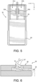
- the device 10 for sample analysis uses an end-user fillable fluid cartridge 30 having a cartridge body 32 having one or more empty chambers 34a, 34b that are devoid of backpressure devices to provide fluid reservoirs for the fluid ejector arrays 20a, 20b in the fluid ejection head chip 40 attached to the cartridge body 32 ( FIGs 4-5 ).
- the end-user fillable fluid cartridge allows researchers to fill the empty chambers 34a, 34b of the end-user fillable fluid cartridge 30 with a small quantity of a variety of fluids for analytical purposes. As a result, it is impractical and undesirable to apply a negative pressure to prime the ejector arrays 20a, 20b since a vacuum source may not be available or may cause cross-contamination of the jetting fluids.
- the priming device for a fluid cartridge, a fluid dispense device configured for priming the fluid cartridge, and a method for priming a fluid cartridge.
- the priming device includes an impact mechanism for a fluid cartridge, wherein the fluid cartridge is devoid of a backpressure device and has a fluid reservoir and an ejection head chip in fluid flow communication with the fluid reservoir.
- the fluid cartridge is an open-top fluid cartridge.
- the impact mechanism is a manually operated impact mechanism. In other embodiments, the impact mechanism is an automated impact mechanism. In still other embodiments, the impact mechanism is an impact rod of an electro-mechanical actuator. In other embodiments, the impact mechanism is an impact head attached to a frame member of a fluid dispense device. In other embodiments, the impact mechanism is a spring biased plunger attached to a fluid cartridge holder.
- the priming device includes an ejection head chip heater. In other embodiments, the ejection head chip heater is disposed on the ejection head chip.
- a fluid dispense device that includes a fluid cartridge devoid of a backpressure device.
- the fluid cartridge has a fluid reservoir and an ejection head chip in fluid flow communication with the fluid reservoir.
- a fluid cartridge translation mechanism is provided for moving the fluid cartridge in a first direction across a substrate.
- An impact head is attached to a frame member of the fluid dispense device and is configured for priming the fluid cartridge.
- a method for priming a fluid cartridge includes providing a fluid cartridge devoid of a backpressure device, wherein the fluid cartridge has one or more fluid reservoirs and one or more ejection head chips in fluid flow communication with the fluid reservoir. A side wall of the fluid cartridge is impacted with an impact mechanism.
- the method includes providing a fluid cartridge devoid of a backpressure device, wherein the fluid cartridge has one or more fluid reservoirs and one or more ejection head chips in fluid flow communication with their respective fluid reservoirs.
- the fluid cartridge is rapidly accelerated in a direction perpendicular to a plane defined by a nozzle plate of the ejection head chip.
- an advantage of the disclosed embodiments is that the priming mechanisms described herein provide an effective and efficient means of priming an ejection head chip without the use of an elaborate vacuum or suction device, particularly when a fluid cartridge is filled with a minimal amount of fluid.
- the apparatus and methods enable the use of open-top cartridges and/or cartridges devoid of backpressure devices thereby allowing the use of fluids selected by the user rather than the use of pre-filled fluid cartridges.
- an end-user fillable fluid cartridge 30 having a cartridge body 32 and one or more empty chambers 34a, 34b therein.
- the chambers 34a, 34b are isolated from one another by a dividing wall 36.
- Each of the chambers 34a and 34b is devoid of a backpressure device.
- Fluid slots 38a and 38b are provided in each of the chambers 34a and 34b to provide flow of fluid from the chambers 34a and 34b to the ejector arrays 20a and 20b attached adjacent to the fluid slots 38a and 38b.
- the ejector arrays 20a and 20b are contained in a fluid ejection head chip 40 attached to the cartridge body 32 by means of an adhesive and a flexible circuit tape 42.
- FIGs. 7 and 8 provide details of the fluid ejector array 20.
- a nozzle plate 44 containing nozzle holes 24 and fluid ejection chambers 46 is attached to a semiconductor substrate 50 having fluid ejectors 52 thereon.
- a portion of an ejector array illustrating a single fluid ejector 52 and corresponding ejection nozzle hole 24 is shown.
- a single fluid ejection head chip 40 may include one or more ejector arrays 20.
- one or more fluid ejection head chips 40 may be attached to the cartridge body 32.
- Ejector arrays 20 typically contain one or more fluid ejectors 52 and corresponding ejection nozzles 24.
- Fluid is provided to each ejector array 20a and 20b from the fluid slots 38a and 38b in the chambers 34a and 34b of the fluid cartridge 30 through a fluid supply via 54 etched through the semiconductor substrate 50.
- the fluid supply via 54 may provide fluid to one or more fluid ejector arrays 56A and 56B.
- the term "open-top” refers primarily to a lack of a backpressure device found in standard fluid cartridges and does not necessitate the lack of a cover or lid on the fluid cartridge.
- the fluid cartridge 30 has one or more chambers 34 therein for filling by a user to provide fluid to the fluid ejection head chip 40.
- a mechanical shock, heat, and/or rapid acceleration of the fluid cartridge 30 is provided to disturb the fluid, thereby promoting capillary action of the fluid from the fluid chambers 46 to the nozzles 24 of the nozzle plate 44 thereby establishing a fluidic connection throughout the ejection head chip 40 and the fluid in the cartridge body 32.
- impact refers to a high force or shock applied to the cartridge body 32 over a short period of time.
- the ejection head chip 40 is a micro electromechanical system that contains one or more fluid paths from the backside 58 of the chip 40 to the front side of the chip 40 and one or more arrays 20 of fluid ejectors 52 that are activated to eject fluid from the external face 28 of the chip and onto a substrate.
- the backside 58 of the ejector head chip 40 is sealed against a bottom wall of the cartridge body 32 and is in fluidic connection with fluid in the chamber(s) 34 of the cartridge body 32.
- the backpressure device in a standard fluid cartridge causes a slight concavity of the meniscus 26 of the fluid at the fluid/air interface. Due to the concavity of the meniscus 26, an impact applied to the fluid cartridge may cause the meniscus 26 to collapse and ingest air into the ejector array 20. Such air bubbles pose a significant issue for reliable jetting of fluid from the ejector array 20.
- the meniscus 56 of the fluid 22 at fluid/air interface is convex as shown in FIG. 9 . The convexity of the meniscus 56 helps prevent ingestion of air as the impact to the fluid cartridge body 32 takes place when priming any arrays in the fluid ejection head chip 40.
- spontaneous priming of the ejection head chip 40 is ideal, the surface tension of many fluids may be too great to allow for the initiation of capillary motion from the backside 58 of the ejector array 20 to the front side of the external face 28 of the ejector array 20. Accordingly, an impact to the cartridge body 32 as shown by arrow 60 ( FIG. 10 ) or a rapid acceleration of the fluid cartridge in a direction perpendicular to a plane defined by the external face 28 of the ejector array 20 may provide a disturbance necessary to cause the fluid 22 to transition to the next part of the fluid path without the need for increasing the pressure head of the fluid, thereby allowing for reliable priming of smaller volumes of fluids.
- Other fluid properties that may impact the capillary action of the fluid through the ejector array 20 include, but are not limited to, viscosity, polarity, and density. The magnitude and frequency of the impact may need to be adjusted for different fluids.
- FIG. 11 illustrates a manual priming device 70 that may be used to provide an impact to an open-top fluid cartridge 72 containing a single chamber 74.
- the device 70 includes a cartridge mounting area 76, a spring biased plunger 78 and a plunger knob 80. Once the fluid cartridge is positioned in the cartridge mounting area 76, a user may pull and release the plunger knob 80 to provide a sharp impact to the cartridge body 82. One or more impacts to the cartridge body 82 by the plunger 78 may be required to adequately prime the fluid ejection head chip attached to the cartridge body 82. While a mechanical plunger 78 is illustrated in FIG. 11 , it will be appreciated that a pneumatic, hydraulic or electro-mechanical actuator may also be used. Likewise, the plunger knob 80 may be rotated to provide a spring-loaded rotational impact to the cartridge body 82.
- the mechanical or otherwise actuated plunger 78 may be incorporated in the fluid ejection device 10.
- FIGs. 12-14 illustrate the use of a linear solenoid activated plunger 84 that is mounted to a frame 86 of a fluid ejection device.
- the fluid cartridge is mounted into a carriage 88 for moving the fluid cartridge and ejection head chip 40 in an x direction back and forth over a substrate as fluid is dispensed from the fluid cartridge.
- the carriage 88 is positioned adjacent to the linear activated solenoid for activating the plunger 90 so that the plunger 90 impacts a side of the carriage 88 to prime the fluid cartridge.
- FIG. 12-14 illustrate the use of a linear solenoid activated plunger 84 that is mounted to a frame 86 of a fluid ejection device.
- the fluid cartridge is mounted into a carriage 88 for moving the fluid cartridge and ejection head chip 40 in an x direction back and forth over a substrate as fluid is dispensed from the fluid cartridge.
- the carriage 88
- the impact position for the cartridge 30 may be slightly outside of a typical operating range which causes the carriage 88 to impact the fixed impact devices 94A and 94B on the frame 92.
- the collision of the carriage 88 with the impact devices 94A and 94B provides energy sufficient to initiate priming of the ejection head chip 40. Since the motion of the carriage 88 is programmable, any sequence of speed and position may be used to ensure priming of the ejection head chip 40.
- an adjustable impact device may be used to adjust the location where the carriage 88 is impacted. While the impact device may be adjustable in the y direction parallel to a plane defined by a side of the carriage 88, the impact device may also be adjustable in the direction of motion of the carriage 88 along the x direction which is perpendicular to the plane defined by the side of the carriage 88.
- the impact device may be hung from an axle to act as a pendulum that repeatedly swings and taps a side of the carriage 88 until all energy of the pendulum is dissipated.
- Counterweights or damping materials may be used to modify the energy of the impact on the carriage 88.
- the empty chamber(s) 34 may be filled and the cartridge 30 rapidly accelerated in a direction perpendicular to a plane defined by the external face 28 of the ejector array 20 ( FIG. 6 ).
- an inertia of the fluid may resist the change in motion and provides enough pressure against a backside 58 of the ejector array 20 ( FIG. 7 ) to initiate capillary wicking action of fluid through the fluid supply via 54 and into the fluid supply channel 48 and fluid ejection chambers 46.
- a cartridge 30 containing fluid could be placed in a centrifugal-type device with the ejector array 20 facing radially outward.
- the inertial resistance of the fluid now coupled with the centrifugal force from the centrifugal-type device may be sufficient to prime the ejector array 20.
- ultrasonic vibrations may be used to induce priming of the ejector array 20 and promote fluid flow to fluid ejection chambers 46.
- priming may be achieved by shaking the cartridge 30.
- an open-topped cartridge 30 FIGs. 4-5
- some fluid adheres to the walls of the empty chambers 34a and 34b and are not recoverable for ejection by the ejector array 20.
- Rapidly moving the cartridge 30 back and forth in the x direction with a high frequency and small amplitude, can help dislodge fluid from the side walls of the chambers 34a and 34b and cause fluid to flow into the fluid slots 38a and 38b where it can then flow to the ejector array 20.
- a series of shaking and then impact, as described above, may produce the optimal conditions for ensuring priming of the ejector array 20 when filling the chambers 34a and 34b of the cartridge 30 with small volumes of fluid.
- Using an open-top four-chamber cartridge required a fluid pressure head of about 28.5 millimeters to induce spontaneous priming of all nozzles 24 of an ejector array 20.
- a fluid pressure head of only 0.5 millimeters consistently primed all nozzles 24 with the use of the impact apparatus of FIG. 11 .
- Using a desktop printer a sequence of carriage movement overdrive commands was able to reliably prime an ejector array 20 with a 50-microliter sample of ink in the fluid cartridge, equivalent to a fluid pressure head of 2.5 millimeters.
- PBS Phosphate buffered saline
- pre-heating the fluid using a heater positioned on the ejection head chip 40 may be sufficient to induce flow of fluid from the cartridge 30 into the ejector array 20.
- Priming sequences have been determined which can reliably prime 30 microliters of phosphate buffered saline (PBS) - in the open-top fluid cartridge 30.
- 30 microliters of fluid provided approximately 2.6 millimeters of fluid pressure head.
- the fluid was heated to 45°C for 20 seconds using the ejection head chip heater on the ejector array 20, and then the carriage 88 was tapped against the frame 92 of the device 10 two times at a speed of about 51 cm per second.
- the temperature, duration, and impact parameters are fluid dependent. It was found that either heating the fluid or tapping against the frame was enough to prime most nozzles of the ejection head chip. Even greater success was found with both heating the fluid and tapping against the frame which consistently primed all nozzles of the ejection head chip. Using a lower preheat temperature required a longer heating period for a given fluid.
- a priming sequence is defined as a series of steps that are used to ensure that a cartridge containing a specific fluid is ready to be dispensed through all nozzles of ejector array 20. Once the cartridge is placed in the carriage of a device, the priming sequence may include one or more of the following steps:
- a priming sequence for a particular fluid may include of one or more of the foregoing steps in any sequence. In some cases, it may be determined that some of the steps are not required. For more difficult to prime fluids, it may be determined that some of these steps need to be repeated more than once.
Landscapes
- Chemical & Material Sciences (AREA)
- Health & Medical Sciences (AREA)
- General Health & Medical Sciences (AREA)
- General Physics & Mathematics (AREA)
- Physics & Mathematics (AREA)
- Life Sciences & Earth Sciences (AREA)
- Analytical Chemistry (AREA)
- Biochemistry (AREA)
- Pathology (AREA)
- Immunology (AREA)
- Chemical Kinetics & Catalysis (AREA)
- Clinical Laboratory Science (AREA)
- Coating Apparatus (AREA)
- Automatic Analysis And Handling Materials Therefor (AREA)
- Feeding, Discharge, Calcimining, Fusing, And Gas-Generation Devices (AREA)
- Sampling And Sample Adjustment (AREA)
Abstract
Description
- The disclosure relates to fluid ejection devices and in particular to methods and apparatus for priming ejection head chips for fluid ejection devices.
- In the medical field, in particular, there is a need for automated sample preparation and analysis. The analysis may be colorimetric analysis or require the staining of samples to better observe the samples under a microscope. Such analysis may include drug sample analysis, blood sample analysis and the like. Assay analysis of blood, for example, provides a number of different factors that are used to determine the health of an individual. When there are a large number of patients that require blood sample analysis, the procedures may be extremely time consuming. For assay analysis, such as drug screenings, it is desirable to deposit miniscule amounts of target reagents to a substrate in order to evaluate their effect and performance on the samples. Traditionally, pipettes - manually or electromechanically actuated - are used to deposit trace substances into these assay samples.
- In order to increase the speed of analysis and to handle larger quantities of samples, automated fluid dispense systems have been developed. The automated systems often require that small quantities of multiple fluids be dispensed through the use of fluid ejection head chips. Thus, the fluid dispense system capable of rapidly processing large quantities of samples to be analyzed is quite elaborate and expensive.
- In an attempt to reduce the cost of the fluid dispense systems, a
fluid ejection device 10 has been developed (FIG. 1 ) that can use the configuration of a conventional inkjet printer device to process samples on glass slides or inwells 12 of a micro-well plate 14 (FIG. 2 ). Thedevice 10 includes ahousing 16 that contains fluid ejection cartridges and a mechanism to move atray 18 containing slides or a micro-well plate through thehousing 16. The fluid ejection cartridges used in thefluid ejection device 10 have anejector array 20 that is in flow communication with afluid 22 in a fluid reservoir of the cartridge (FIGs. 3 and 4 ). - A conventional ink jet printer cartridge includes a backpressure device such as a bladder or a piece of absorbent material such as foam or felt which allows a large quantity of jetting fluid to be stored in the cartridge without the
fluid 22 drooling or dripping out of theejection head chip 40 attached to the cartridge. Due to the nature of the backpressure device, thefluid 22 in anozzle 24 on theejector array 20 maintains aconcave meniscus 26 with respect to theexternal face 28 of theejector array 20 as shown inFIG. 3 . Accordingly, it is common practice to prime theejector array 20 by using a negative pressure to remove air bubbles in the fluid and to pull fluid through the fluidic paths in the ejection head chip. It is also common practice to protect the inkjet printer cartridge from sudden impacts during shipping and handling since impacting the ejection head chip could lead to the ingestion of air bubbles into a fluid cartridge containing a back-pressure device. - However, the
device 10 for sample analysis uses an end-userfillable fluid cartridge 30 having acartridge body 32 having one or moreempty chambers fluid ejector arrays ejection head chip 40 attached to the cartridge body 32 (FIGs 4-5 ). The end-user fillable fluid cartridge allows researchers to fill theempty chambers fillable fluid cartridge 30 with a small quantity of a variety of fluids for analytical purposes. As a result, it is impractical and undesirable to apply a negative pressure to prime theejector arrays ejector array 20 is reliably primed in order to dispense highly precise doses ordroplets 37 of a jetting fluid for such analytical purposes as shown inFIG. 6 . Depending on the fluid properties, the resistance of the fluid to spontaneous priming of theejector array 20, and the low volume of fluid in thecartridge 30, there is a need for a reliable priming mechanism for the end-userfillable fluid cartridges 30 used in suchfluid ejection devices 10. - In view of the foregoing, embodiments of the disclosure provide a priming device for a fluid cartridge, a fluid dispense device configured for priming the fluid cartridge, and a method for priming a fluid cartridge. In one embodiment, the priming device includes an impact mechanism for a fluid cartridge, wherein the fluid cartridge is devoid of a backpressure device and has a fluid reservoir and an ejection head chip in fluid flow communication with the fluid reservoir.
- In some embodiments, the fluid cartridge is an open-top fluid cartridge.
- In some embodiments, the impact mechanism is a manually operated impact mechanism. In other embodiments, the impact mechanism is an automated impact mechanism. In still other embodiments, the impact mechanism is an impact rod of an electro-mechanical actuator. In other embodiments, the impact mechanism is an impact head attached to a frame member of a fluid dispense device. In other embodiments, the impact mechanism is a spring biased plunger attached to a fluid cartridge holder.
- In some embodiments, the priming device includes an ejection head chip heater. In other embodiments, the ejection head chip heater is disposed on the ejection head chip.
- In some embodiments there is provided a fluid dispense device that includes a fluid cartridge devoid of a backpressure device. The fluid cartridge has a fluid reservoir and an ejection head chip in fluid flow communication with the fluid reservoir. A fluid cartridge translation mechanism is provided for moving the fluid cartridge in a first direction across a substrate. An impact head is attached to a frame member of the fluid dispense device and is configured for priming the fluid cartridge.
- In some embodiments, there is provided a method for priming a fluid cartridge. The method includes providing a fluid cartridge devoid of a backpressure device, wherein the fluid cartridge has one or more fluid reservoirs and one or more ejection head chips in fluid flow communication with the fluid reservoir. A side wall of the fluid cartridge is impacted with an impact mechanism.
- In some embodiments, there is provided method for priming a fluid cartridge. The method includes providing a fluid cartridge devoid of a backpressure device, wherein the fluid cartridge has one or more fluid reservoirs and one or more ejection head chips in fluid flow communication with their respective fluid reservoirs. The fluid cartridge is rapidly accelerated in a direction perpendicular to a plane defined by a nozzle plate of the ejection head chip.
- An advantage of the disclosed embodiments, is that the priming mechanisms described herein provide an effective and efficient means of priming an ejection head chip without the use of an elaborate vacuum or suction device, particularly when a fluid cartridge is filled with a minimal amount of fluid. The apparatus and methods enable the use of open-top cartridges and/or cartridges devoid of backpressure devices thereby allowing the use of fluids selected by the user rather than the use of pre-filled fluid cartridges.
-
-
FIG. 1 is a perspective view of a fluid dispense device for use with priming mechanisms described according to the disclosure. -
FIG. 2 is a perspective view of a micro-well plate in a tray for use with the fluid dispense device ofFIG. 1 . -
FIG. 3 is a cross-sectional view, not to scale, of a portion of a primed fluid ejector array for a fluid cartridge containing a backpressure device. -
FIG. 4 is a perspective view of an open-top fluid cartridge for use with the fluid dispense device ofFIG. 1 . -
FIG. 5 is a top plan view of the open-top fluid cartridge ofFIG. 4 . -
FIG. 6 is a cross-sectional view, not to scale, of a portion of a fluid ejection head chip containing fluid subsequent to priming, in the process of ejecting fluid. -
FIG. 7 is a cross-sectional view, not to scale, of a portion of a fluid ejection head chip showing fluid flow paths therein. -
FIG. 8 is a top plan view, not to scale, of the fluid ejection head chip ofFIG. 7 . -
FIG. 9 is a cross-sectional view, not to scale, of a portion of a fluid ejection head chip containing fluid for a fluid cartridge devoid of a backpressure device. -
FIG. 10 is a top plan view of the open-top fluid cartridge ofFIG. 4 showing a direction of impact for priming the fluid cartridge. -
FIG. 11 is a perspective view of a stand-alone priming device according to a first embodiment of the disclosure. -
FIG. 12 is an elevational front view of a cartridge carriage and fluid dispense device frame containing a priming device according to a second embodiment of the disclosure. -
FIG. 13 is a perspective view of the cartridge carriage and priming device on the frame of the fluid dispense device ofFIG. 12 . -
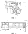
FIG. 14 is an elevational front view of a cartridge carriage and fluid dispense device frame containing a priming device according to a third embodiment of the disclosure. -
FIG. 15 is a perspective view of the cartridge carriage and priming device on the frame of the fluid dispense device ofFIG. 14 . - With reference to
FIGs. 4-5 there is illustrated an end-userfillable fluid cartridge 30 having acartridge body 32 and one or moreempty chambers chambers wall 36. Each of thechambers Fluid slots chambers chambers ejector arrays fluid slots ejector arrays ejection head chip 40 attached to thecartridge body 32 by means of an adhesive and aflexible circuit tape 42. -
FIGs. 7 and 8 provide details of thefluid ejector array 20. A nozzle plate 44 containing nozzle holes 24 andfluid ejection chambers 46 is attached to asemiconductor substrate 50 havingfluid ejectors 52 thereon. For simplicity, a portion of an ejector array illustrating asingle fluid ejector 52 and correspondingejection nozzle hole 24 is shown. However, a single fluidejection head chip 40 may include one ormore ejector arrays 20. Likewise, one or more fluid ejection head chips 40 may be attached to thecartridge body 32.Ejector arrays 20 typically contain one or morefluid ejectors 52 andcorresponding ejection nozzles 24. Fluid is provided to eachejector array fluid slots chambers fluid cartridge 30 through a fluid supply via 54 etched through thesemiconductor substrate 50. As shown inFIG. 8 , the fluid supply via 54 may provide fluid to one or morefluid ejector arrays - For the purposes of the disclosure, the term "open-top" refers primarily to a lack of a backpressure device found in standard fluid cartridges and does not necessitate the lack of a cover or lid on the fluid cartridge. However, the
fluid cartridge 30 has one or more chambers 34 therein for filling by a user to provide fluid to the fluidejection head chip 40. In order to prime the fluidejection head chip 40 with fluid, a mechanical shock, heat, and/or rapid acceleration of thefluid cartridge 30 is provided to disturb the fluid, thereby promoting capillary action of the fluid from thefluid chambers 46 to thenozzles 24 of the nozzle plate 44 thereby establishing a fluidic connection throughout theejection head chip 40 and the fluid in thecartridge body 32. The term "impact" as used herein refers to a high force or shock applied to thecartridge body 32 over a short period of time. - The
ejection head chip 40 is a micro electromechanical system that contains one or more fluid paths from thebackside 58 of thechip 40 to the front side of thechip 40 and one ormore arrays 20 offluid ejectors 52 that are activated to eject fluid from theexternal face 28 of the chip and onto a substrate. Thebackside 58 of theejector head chip 40 is sealed against a bottom wall of thecartridge body 32 and is in fluidic connection with fluid in the chamber(s) 34 of thecartridge body 32. - As described above with reference to
FIG. 3 , the backpressure device in a standard fluid cartridge causes a slight concavity of themeniscus 26 of the fluid at the fluid/air interface. Due to the concavity of themeniscus 26, an impact applied to the fluid cartridge may cause themeniscus 26 to collapse and ingest air into theejector array 20. Such air bubbles pose a significant issue for reliable jetting of fluid from theejector array 20. However, in open-top fluid cartridges 30, that do not contain a backpressure device, themeniscus 56 of the fluid 22 at fluid/air interface is convex as shown inFIG. 9 . The convexity of themeniscus 56 helps prevent ingestion of air as the impact to thefluid cartridge body 32 takes place when priming any arrays in the fluidejection head chip 40. - Although spontaneous priming of the
ejection head chip 40 is ideal, the surface tension of many fluids may be too great to allow for the initiation of capillary motion from thebackside 58 of theejector array 20 to the front side of theexternal face 28 of theejector array 20. Accordingly, an impact to thecartridge body 32 as shown by arrow 60 (FIG. 10 ) or a rapid acceleration of the fluid cartridge in a direction perpendicular to a plane defined by theexternal face 28 of theejector array 20 may provide a disturbance necessary to cause the fluid 22 to transition to the next part of the fluid path without the need for increasing the pressure head of the fluid, thereby allowing for reliable priming of smaller volumes of fluids. Other fluid properties that may impact the capillary action of the fluid through theejector array 20 include, but are not limited to, viscosity, polarity, and density. The magnitude and frequency of the impact may need to be adjusted for different fluids. -
FIG. 11 illustrates amanual priming device 70 that may be used to provide an impact to an open-top fluid cartridge 72 containing asingle chamber 74. Thedevice 70 includes acartridge mounting area 76, a springbiased plunger 78 and aplunger knob 80. Once the fluid cartridge is positioned in thecartridge mounting area 76, a user may pull and release theplunger knob 80 to provide a sharp impact to thecartridge body 82. One or more impacts to thecartridge body 82 by theplunger 78 may be required to adequately prime the fluid ejection head chip attached to thecartridge body 82. While amechanical plunger 78 is illustrated inFIG. 11 , it will be appreciated that a pneumatic, hydraulic or electro-mechanical actuator may also be used. Likewise, theplunger knob 80 may be rotated to provide a spring-loaded rotational impact to thecartridge body 82. - In some embodiments, the mechanical or otherwise actuated
plunger 78 may be incorporated in thefluid ejection device 10.FIGs. 12-14 illustrate the use of a linear solenoid activatedplunger 84 that is mounted to aframe 86 of a fluid ejection device. The fluid cartridge is mounted into acarriage 88 for moving the fluid cartridge andejection head chip 40 in an x direction back and forth over a substrate as fluid is dispensed from the fluid cartridge. After filling the fluid cartridge, thecarriage 88 is positioned adjacent to the linear activated solenoid for activating theplunger 90 so that theplunger 90 impacts a side of thecarriage 88 to prime the fluid cartridge.FIG. 12 is a front, elevational view, of theframe 86,carriage 88, andlinear solenoid plunger 84.FIG. 13 is a top perspective view of thelinear solenoid plunger 84,frame 86, andcarriage 88 ofFIG. 12 . - Another embodiment of the disclosure is illustrated in
FIGs. 14-15 . In this embodiment, rather than using adedicated impactor 84, theframe 92 of the fluid ejection device contains one or morefixed impact devices cartridge 30 as thecarriage 88 moves from one side of the frame 92 (FIG. 14 ) to the other side of the frame 92 (FIG. 15 ). According to the embodiment, thecarriage 88 of thedevice 10 is driven by a motor which may be programmed to move thecarriage 88 to a specified position to impact thecartridge 30 onimpact device cartridge 30 may be slightly outside of a typical operating range which causes thecarriage 88 to impact thefixed impact devices frame 92. The collision of thecarriage 88 with theimpact devices ejection head chip 40. Since the motion of thecarriage 88 is programmable, any sequence of speed and position may be used to ensure priming of theejection head chip 40. - While the foregoing embodiments illustrate fixed impact points for the
carriage 88 relative to theframe device 10, an adjustable impact device may be used to adjust the location where thecarriage 88 is impacted. While the impact device may be adjustable in the y direction parallel to a plane defined by a side of thecarriage 88, the impact device may also be adjustable in the direction of motion of thecarriage 88 along the x direction which is perpendicular to the plane defined by the side of thecarriage 88. - In other embodiments, instead of the impact device being rigidly mounted, the impact device may be hung from an axle to act as a pendulum that repeatedly swings and taps a side of the
carriage 88 until all energy of the pendulum is dissipated. Counterweights or damping materials may be used to modify the energy of the impact on thecarriage 88. - In yet another embodiment, the empty chamber(s) 34 may be filled and the
cartridge 30 rapidly accelerated in a direction perpendicular to a plane defined by theexternal face 28 of the ejector array 20 (FIG. 6 ). Without desiring to be bound by theoretical considerations, it is believed that an inertia of the fluid may resist the change in motion and provides enough pressure against abackside 58 of the ejector array 20 (FIG. 7 ) to initiate capillary wicking action of fluid through the fluid supply via 54 and into thefluid supply channel 48 andfluid ejection chambers 46. In a similar manner, acartridge 30 containing fluid could be placed in a centrifugal-type device with theejector array 20 facing radially outward. Thus, the inertial resistance of the fluid now coupled with the centrifugal force from the centrifugal-type device may be sufficient to prime theejector array 20. In still another embodiment, ultrasonic vibrations may be used to induce priming of theejector array 20 and promote fluid flow tofluid ejection chambers 46. - In some embodiments, priming may be achieved by shaking the
cartridge 30. Often when an open-topped cartridge 30 (FIGs. 4-5 ) is filled with a pipette, some fluid adheres to the walls of theempty chambers ejector array 20. Rapidly moving thecartridge 30 back and forth in the x direction, with a high frequency and small amplitude, can help dislodge fluid from the side walls of thechambers fluid slots ejector array 20. A series of shaking and then impact, as described above, may produce the optimal conditions for ensuring priming of theejector array 20 when filling thechambers cartridge 30 with small volumes of fluid. - Additionally, since the
ejector array 20 is typically not centered with respect to thechambers fluid slot 38a feeding theejector array 20 is offset to the right side of thechamber 34a, tapping theright sidewall 98 of the cartridge body 32 (FIG. 10 ) may improve the priming process. - The following non-limiting examples illustrate an impact process for priming an
ejector array 20. - Using an open-top four-chamber cartridge required a fluid pressure head of about 28.5 millimeters to induce spontaneous priming of all
nozzles 24 of anejector array 20. Using the same fluid, a fluid pressure head of only 0.5 millimeters consistently primed allnozzles 24 with the use of the impact apparatus ofFIG. 11 . Using a desktop printer, a sequence of carriage movement overdrive commands was able to reliably prime anejector array 20 with a 50-microliter sample of ink in the fluid cartridge, equivalent to a fluid pressure head of 2.5 millimeters. - Phosphate buffered saline (PBS) is a common reagent used in biochemical assays. Two solutions, with or without a sorbitan monolaurate non-ionic surfactant, underwent testing. Spontaneous priming of an ejection head chip with either solution was undeterminable, both requiring a fluid pressure head greater than the maximum testing fluid height of 43 millimeters. Using the impact apparatus of
FIG. 11 , the PBS without the surfactant was able to reliably prime the ejection head chip with 2.3 millimeters of fluid pressure head while PBS with added 0.04% surfactant was able to reliably prime the ejection head chip with 2.0 millimeters of fluid pressure head. A carriage impact sequence was determined which could reliably prime the ejection head chip with the PBS and surfactant solution at a fluid pressure head of 3.4 millimeters. - In other embodiments, pre-heating the fluid using a heater positioned on the
ejection head chip 40 may be sufficient to induce flow of fluid from thecartridge 30 into theejector array 20. - Priming sequences have been determined which can reliably prime 30 microliters of phosphate buffered saline (PBS) - in the open-
top fluid cartridge 30. In this test, 30 microliters of fluid provided approximately 2.6 millimeters of fluid pressure head. The fluid was heated to 45°C for 20 seconds using the ejection head chip heater on theejector array 20, and then thecarriage 88 was tapped against theframe 92 of thedevice 10 two times at a speed of about 51 cm per second. The temperature, duration, and impact parameters are fluid dependent. It was found that either heating the fluid or tapping against the frame was enough to prime most nozzles of the ejection head chip. Even greater success was found with both heating the fluid and tapping against the frame which consistently primed all nozzles of the ejection head chip. Using a lower preheat temperature required a longer heating period for a given fluid. - In accordance with the disclosed embodiments, a priming sequence is defined as a series of steps that are used to ensure that a cartridge containing a specific fluid is ready to be dispensed through all nozzles of
ejector array 20. Once the cartridge is placed in the carriage of a device, the priming sequence may include one or more of the following steps: - 1) Tapping the carriage against the frame of the device to impart an impulse to the ejection head chip.
- 2) Repeating step (1) multiple times, with or without pauses in between.
- 3) Impacting the carriage against the frame of the fluid ejection device at various speeds.
- 4) Warming the fluid by using the ejection head chip heater on the ejection head chip.
- 5) Modifying the temperature and duration of heating for a specific fluid or application.
- 6) Ejecting fluid from the ejection head chip.
- Accordingly, a priming sequence for a particular fluid may include of one or more of the foregoing steps in any sequence. In some cases, it may be determined that some of the steps are not required. For more difficult to prime fluids, it may be determined that some of these steps need to be repeated more than once.
- For the purposes of this specification and appended claims, unless otherwise indicated, all numbers expressing quantities, percentages or proportions, and other numerical values used in the specification and claims, are to be understood as being modified in all instances by the term "about." Accordingly, unless indicated to the contrary, the numerical parameters set forth in the following specification and attached claims are approximations that can vary depending upon the desired properties sought to be obtained by the present disclosure. At the very least, and not as an attempt to limit the application of the doctrine of equivalents to the scope of the claims, each numerical parameter should at least be construed in light of the number of reported significant digits and by applying ordinary rounding techniques.
- While particular embodiments have been described, alternatives, modifications, variations, improvements, and substantial equivalents that are or can be presently unforeseen can arise to applicants or others skilled in the art. Accordingly, the appended claims as filed and as they can be amended are intended to embrace all such alternatives, modifications variations, improvements, and substantial equivalents.
Claims (18)
- A priming device (70) for a fluid cartridge (72), characterized in that comprising:an impact mechanism (78, 80) for the fluid cartridge (72),wherein the fluid cartridge (72) is devoid of a backpressure device and has a fluid reservoir (74) and an ejection head chip (40) in fluid flow communication with the fluid reservoir (74).
- The priming device (70) of claim 1, wherein
the fluid cartridge (72) is an open-top fluid cartridge. - The priming device (70) of claim 1, wherein
the impact mechanism (78, 80) is a manually operated impact mechanism. - The priming device (70) of claim 1, wherein
the impact mechanism (78, 80) is an automated impact mechanism. - The priming device (70) of claim 4, wherein
the impact mechanism (78, 80) comprises an impact rod (90) of a linear solenoid (84). - The priming device (70) of claim 1, wherein
the impact mechanism (78, 80) comprises an impact head (94A, 94B) attached to a frame member (92) of a fluid dispense device (10). - The priming device (70) of claim 1, wherein
the impact mechanism (78, 80) comprises a spring biased plunger (78) attached to a fluid cartridge holder (76). - The priming device (70) of claim 1, further comprising:
an ejection head chip heater. - The priming device (70) of claim 8, wherein
the ejection head chip heater is disposed on the ejection head chip (40). - A fluid dispense device (10) comprising:a fluid cartridge (72) devoid of a backpressure device, wherein the fluid cartridge (72) has a fluid reservoir (74) and an ejection head chip (40) in fluid flow communication with the fluid reservoir (74);a fluid cartridge translation mechanism for moving the fluid cartridge (72) in a first direction across a substrate; andan impact head (94A, 94B) attached to a frame member (92) of the fluid dispense device (10) configured for priming the fluid cartridge (72).
- The fluid dispense device (10) of claim 10, wherein
the impact head (94A, 94B) comprises an impact rod (90) of a linear solenoid (84). - The fluid dispense device (10) of claim 10, wherein
the impact head (94A, 94B) comprises a spring biased plunger (78). - A method for priming a fluid cartridge (72), characterized in that comprising:providing the fluid cartridge (72) devoid of a backpressure device, wherein the fluid cartridge (72) has a fluid reservoir (74) and an ejection head chip (40) in fluid flow communication with the fluid reservoir (74); andimpacting a side wall of the fluid cartridge (72) with an impact mechanism (78, 80).
- The method of claim 13, further comprising:
heating the ejection head chip (40). - The method of claim 13, wherein
the impact mechanism (78, 80) is attached to a frame (92) of a fluid dispense device (10) containing the fluid cartridge (72). - The method of claim 13, wherein
the impact mechanism (78, 80) comprises a cartridge holder (76) having a spring biased plunger (78) for impacting the side wall of the fluid cartridge (72). - The method of claim 13, wherein
the impact mechanism (78, 80) comprises a linear solenoid (84) and an impact rod (90). - A method for priming a fluid cartridge (72), characterized in that comprising:providing the fluid cartridge (72) devoid of a backpressure device, wherein the fluid cartridge (72) has a fluid reservoir (74) and an ejection head chip (40) in fluid flow communication with the fluid reservoir (74); andrapidly accelerating the fluid cartridge (72) in a direction perpendicular to a plane defined by a nozzle plate (44) of the ejection head chip (40).
Applications Claiming Priority (1)
| Application Number | Priority Date | Filing Date | Title |
|---|---|---|---|
| US17/809,312 US11858268B1 (en) | 2022-06-28 | 2022-06-28 | Ejection head priming mechanism |
Publications (1)
| Publication Number | Publication Date |
|---|---|
| EP4299179A1 true EP4299179A1 (en) | 2024-01-03 |
Family
ID=86657562
Family Applications (1)
| Application Number | Title | Priority Date | Filing Date |
|---|---|---|---|
| EP23176781.5A Withdrawn EP4299179A1 (en) | 2022-06-28 | 2023-06-01 | Priming device and priming method for fluid cartridge, and fluid dispense device |
Country Status (4)
| Country | Link |
|---|---|
| US (1) | US11858268B1 (en) |
| EP (1) | EP4299179A1 (en) |
| JP (1) | JP2024004475A (en) |
| CN (1) | CN117309514A (en) |
Citations (4)
| Publication number | Priority date | Publication date | Assignee | Title |
|---|---|---|---|---|
| EP2848372A2 (en) * | 2013-09-12 | 2015-03-18 | Stanley Black & Decker, Inc. | Hammer with bend resistant handle |
| JP2019106521A (en) * | 2018-03-30 | 2019-06-27 | 株式会社オンガエンジニアリング | Solenoid type electromagnetic hammer |
| WO2020222834A1 (en) * | 2019-04-30 | 2020-11-05 | Hewlett-Packard Development Company, L.P. | Fluid ejection and circulation |
| WO2022081158A1 (en) * | 2020-10-15 | 2022-04-21 | Hewlett-Packard Development Company, L.P. | Recirculation of fluid within a fluidic ejection device |
Family Cites Families (10)
| Publication number | Priority date | Publication date | Assignee | Title |
|---|---|---|---|---|
| KR970009107B1 (en) | 1993-03-30 | 1997-06-05 | Samsung Electronics Co Ltd | Ink-jet recording method and apparatus thereof |
| JP3346064B2 (en) * | 1993-12-28 | 2002-11-18 | セイコーエプソン株式会社 | Inkjet cartridge |
| US5957167A (en) | 1997-12-18 | 1999-09-28 | Pharmacopeia, Inc. | Article for dispensing small volumes of liquid |
| US6491387B1 (en) | 2000-09-18 | 2002-12-10 | Rodney Bruce Mayfield | Ink jet cleaning method and apparatus utilizing vacuum impregnation and centrifuge |
| US7121647B2 (en) * | 2003-10-03 | 2006-10-17 | Lexmark International, Inc. | Method of applying an encapsulant material to an ink jet printhead |
| JP4778803B2 (en) | 2006-01-31 | 2011-09-21 | 富士通株式会社 | Solution filling device |
| JP2008036947A (en) * | 2006-08-04 | 2008-02-21 | Ricoh Co Ltd | Liquid ejection device and liquid ejection method |
| JP4561918B2 (en) * | 2008-12-10 | 2010-10-13 | セイコーエプソン株式会社 | Inkjet recording device |
| JP2011008228A (en) | 2009-05-28 | 2011-01-13 | Seiko Epson Corp | Method for controlling droplet discharge device, and droplet discharge device |
| JP2017015466A (en) * | 2015-06-29 | 2017-01-19 | 東芝テック株式会社 | Droplet ejector |
-
2022
- 2022-06-28 US US17/809,312 patent/US11858268B1/en active Active
-
2023
- 2023-06-01 EP EP23176781.5A patent/EP4299179A1/en not_active Withdrawn
- 2023-06-05 CN CN202310652683.8A patent/CN117309514A/en active Pending
- 2023-06-20 JP JP2023101236A patent/JP2024004475A/en active Pending
Patent Citations (4)
| Publication number | Priority date | Publication date | Assignee | Title |
|---|---|---|---|---|
| EP2848372A2 (en) * | 2013-09-12 | 2015-03-18 | Stanley Black & Decker, Inc. | Hammer with bend resistant handle |
| JP2019106521A (en) * | 2018-03-30 | 2019-06-27 | 株式会社オンガエンジニアリング | Solenoid type electromagnetic hammer |
| WO2020222834A1 (en) * | 2019-04-30 | 2020-11-05 | Hewlett-Packard Development Company, L.P. | Fluid ejection and circulation |
| WO2022081158A1 (en) * | 2020-10-15 | 2022-04-21 | Hewlett-Packard Development Company, L.P. | Recirculation of fluid within a fluidic ejection device |
Also Published As
| Publication number | Publication date |
|---|---|
| US20230415480A1 (en) | 2023-12-28 |
| CN117309514A (en) | 2023-12-29 |
| JP2024004475A (en) | 2024-01-16 |
| US11858268B1 (en) | 2024-01-02 |
Similar Documents
| Publication | Publication Date | Title |
|---|---|---|
| JP3463929B2 (en) | Microdispensing device without volume sensor, dispensing device array, and usage of microdispensing device | |
| JP4028716B2 (en) | Multiple ejector system for dispensing biofluids | |
| EP1274508B1 (en) | A device for dispensing accurately-controlled small doses of liquid | |
| EP1137489B1 (en) | Fluid dispenser and dispensing methods | |
| EP2613889B1 (en) | A liquid droplet dispenser | |
| US7160511B2 (en) | Liquid pipetting apparatus and micro array manufacturing apparatus | |
| JP7138637B2 (en) | Pipetting device for improved pulsed liquid pipetting | |
| JP2000500567A (en) | Microwell plate | |
| AU746828B2 (en) | Apparatus for dispensing a predetermined volume of a liquid | |
| US20060171854A1 (en) | Pipette tip, pipetting device, pipette tip actuating device and method for pipetting in the NL range | |
| JP2004506917A (en) | Apparatus and method for supplying microdroplets on a substrate in a non-contact manner | |
| EP1209467B1 (en) | Devices for biofluid drop ejection | |
| US11858268B1 (en) | Ejection head priming mechanism | |
| JP2004513376A (en) | Apparatus and system for dispensing or aspirating / dispensing a liquid sample | |
| EP1208912B1 (en) | Testing methods and configurations for multi-ejector system | |
| US11279137B2 (en) | Droplet ejectors aimed at target media | |
| JP2001228162A (en) | Liquid ejection device, liquid ejection head, and ejection method | |
| EP2188003B1 (en) | Fluid transfer method | |
| WO2003004275A9 (en) | Droplet dispensing system | |
| JP2004251820A (en) | Dispensing method | |
| WO2003101369A2 (en) | Liquid transfer device |
Legal Events
| Date | Code | Title | Description |
|---|---|---|---|
| PUAI | Public reference made under article 153(3) epc to a published international application that has entered the european phase |
Free format text: ORIGINAL CODE: 0009012 |
|
| STAA | Information on the status of an ep patent application or granted ep patent |
Free format text: STATUS: THE APPLICATION HAS BEEN PUBLISHED |
|
| AK | Designated contracting states |
Kind code of ref document: A1 Designated state(s): AL AT BE BG CH CY CZ DE DK EE ES FI FR GB GR HR HU IE IS IT LI LT LU LV MC ME MK MT NL NO PL PT RO RS SE SI SK SM TR |
|
| STAA | Information on the status of an ep patent application or granted ep patent |
Free format text: STATUS: REQUEST FOR EXAMINATION WAS MADE |
|
| 17P | Request for examination filed |
Effective date: 20240325 |
|
| RBV | Designated contracting states (corrected) |
Designated state(s): AL AT BE BG CH CY CZ DE DK EE ES FI FR GB GR HR HU IE IS IT LI LT LU LV MC ME MK MT NL NO PL PT RO RS SE SI SK SM TR |
|
| STAA | Information on the status of an ep patent application or granted ep patent |
Free format text: STATUS: THE APPLICATION HAS BEEN WITHDRAWN |
|
| 18W | Application withdrawn |
Effective date: 20241126 |
|
| 19U | Interruption of proceedings before grant |
Effective date: 20241024 |