EP4299151A1 - Insert for a controller - Google Patents
Insert for a controller Download PDFInfo
- Publication number
- EP4299151A1 EP4299151A1 EP23179435.5A EP23179435A EP4299151A1 EP 4299151 A1 EP4299151 A1 EP 4299151A1 EP 23179435 A EP23179435 A EP 23179435A EP 4299151 A1 EP4299151 A1 EP 4299151A1
- Authority
- EP
- European Patent Office
- Prior art keywords
- insert
- joystick
- casing
- stem
- controller
- Prior art date
- Legal status (The legal status is an assumption and is not a legal conclusion. Google has not performed a legal analysis and makes no representation as to the accuracy of the status listed.)
- Pending
Links
Images


Classifications
-
- A—HUMAN NECESSITIES
- A63—SPORTS; GAMES; AMUSEMENTS
- A63F—CARD, BOARD, OR ROULETTE GAMES; INDOOR GAMES USING SMALL MOVING PLAYING BODIES; VIDEO GAMES; GAMES NOT OTHERWISE PROVIDED FOR
- A63F13/00—Video games, i.e. games using an electronically generated display having two or more dimensions
- A63F13/20—Input arrangements for video game devices
- A63F13/24—Constructional details thereof, e.g. game controllers with detachable joystick handles
-
- A—HUMAN NECESSITIES
- A63—SPORTS; GAMES; AMUSEMENTS
- A63F—CARD, BOARD, OR ROULETTE GAMES; INDOOR GAMES USING SMALL MOVING PLAYING BODIES; VIDEO GAMES; GAMES NOT OTHERWISE PROVIDED FOR
- A63F13/00—Video games, i.e. games using an electronically generated display having two or more dimensions
- A63F13/20—Input arrangements for video game devices
- A63F13/21—Input arrangements for video game devices characterised by their sensors, purposes or types
- A63F13/218—Input arrangements for video game devices characterised by their sensors, purposes or types using pressure sensors, e.g. generating a signal proportional to the pressure applied by the player
-
- A—HUMAN NECESSITIES
- A63—SPORTS; GAMES; AMUSEMENTS
- A63F—CARD, BOARD, OR ROULETTE GAMES; INDOOR GAMES USING SMALL MOVING PLAYING BODIES; VIDEO GAMES; GAMES NOT OTHERWISE PROVIDED FOR
- A63F13/00—Video games, i.e. games using an electronically generated display having two or more dimensions
- A63F13/20—Input arrangements for video game devices
- A63F13/22—Setup operations, e.g. calibration, key configuration or button assignment
-
- A—HUMAN NECESSITIES
- A63—SPORTS; GAMES; AMUSEMENTS
- A63F—CARD, BOARD, OR ROULETTE GAMES; INDOOR GAMES USING SMALL MOVING PLAYING BODIES; VIDEO GAMES; GAMES NOT OTHERWISE PROVIDED FOR
- A63F13/00—Video games, i.e. games using an electronically generated display having two or more dimensions
- A63F13/90—Constructional details or arrangements of video game devices not provided for in groups A63F13/20 or A63F13/25, e.g. housing, wiring, connections or cabinets
- A63F13/98—Accessories, i.e. detachable arrangements optional for the use of the video game device, e.g. grip supports of game controllers
-
- G—PHYSICS
- G06—COMPUTING OR CALCULATING; COUNTING
- G06F—ELECTRIC DIGITAL DATA PROCESSING
- G06F3/00—Input arrangements for transferring data to be processed into a form capable of being handled by the computer; Output arrangements for transferring data from processing unit to output unit, e.g. interface arrangements
- G06F3/01—Input arrangements or combined input and output arrangements for interaction between user and computer
- G06F3/03—Arrangements for converting the position or the displacement of a member into a coded form
- G06F3/033—Pointing devices displaced or positioned by the user, e.g. mice, trackballs, pens or joysticks; Accessories therefor
- G06F3/0338—Pointing devices displaced or positioned by the user, e.g. mice, trackballs, pens or joysticks; Accessories therefor with detection of limited linear or angular displacement of an operating part of the device from a neutral position, e.g. isotonic or isometric joysticks
Definitions
- the present technique relates to the field of computer input devices and more particularly to an insert for a handheld controller employing one or more joysticks.
- the DualSense ® controller 80 is illustrated as an example of a handheld controller.
- a handheld controller typically has two handle sections 81L,R and a central body 81C.
- Various controls are distributed over the controller, typically in local groups. Examples include a left button group 82L, which may comprise directional controls and/or one or more shoulder buttons, and similarly right button group 82R, which comprise function controls and/or one or more shoulder buttons.
- the controller may also comprise one or more system buttons 86, which typically cause interaction with an operating system of the entertainment device rather than with a game or other application currently running on it; such buttons may summon a system menu, or allow for recording or sharing of displayed content.
- the controller may comprise one or more other elements such as a touchpad 88, a light for optical tracking (not shown), a screen (not shown), haptic feedback elements (not shown), and the like.
- the controller also includes left and/or right joysticks 84L,R, which may optionally also be operable as buttons by pressing down on them.
- Each joystick 84L,R provides a two-dimensional input (X,Y) which may be used to induce a corresponding effect on a displayed graphic.
- Each joystick 84L, R sometimes called an analogue stick or more generally a control stick - provides positional input to a computing platform based on the position of the protrusion relative to a mechanical "centre" position within the controller body.
- each joystick 84L,R typically rests on a top surface (which may be referred to as a thumb pad) of each joystick 84L,R and pressure applied by the thumb may change the displacement of the joystick 84L,R relative to the centre position, which may serve as a reference position.
- a pivoting base of each joystick 84L,R may be coupled to two or more potentiometers housed within the controller body to provide a continuous electrical output proportional to the displacement of the joystick 84L,R relative to the central reference position (hence, the term "analogue stick").
- the controller shown in Figure 1 is an example of a controller comprising a joystick and a casing at least partially surrounding the joystick.
- the joystick 84L,R is nevertheless limited to the provision of a continuous electrical output proportional to the displacement of the joystick.
- This can present issues for some uses, such as users with mobility issues (e.g. finger joint mobility issues, which may affect the thumbs). Users with such mobility issues may have a limited range of motion in their thumb(s), and hence may be unable to make use of the full range of motion of the joystick.
- dedicated "accessible" controllers can be provided, which can be designed to be easier to use for people with mobility issues.
- providing multiple different controller designs for users with varying abilities can be expensive, and hence such controllers can be prohibitively expensive for users with mobility issues.
- the present invention seeks to mitigate or alleviate this problem.
- an insert for a controller as defined in claim 1.
- an entertainment device as defined in claim 12.
- Coupled and “connected,” along with their derivatives, may be used herein to describe structural relationships between components of the apparatus for performing the operations herein. It should be understood that these terms are not intended as synonyms for each other. Rather, in particular embodiments, “connected” is used to indicate that two or more elements are in direct physical or electrical contact with each other while “coupled” is used to indicate two or more elements are in either direct or indirect (with other intervening elements between them) physical or electrical contact with each other, and/or that the two or more elements co-operate or communicate with each other (e.g., as in a cause an effect relationship).
- an example of an entertainment system 200 is a computer or console such as the Sony ® PlayStation 5 ® (PS5).
- PS5 Sony ® PlayStation 5 ®
- the entertainment system 200 comprises a central processor 220. This may be a single or multi core processor, for example comprising eight cores as in the PS5.
- the entertainment system also comprises a graphical processing unit or GPU 30.
- the GPU can be physically separate to the CPU, or integrated with the CPU as a system on a chip (SoC) as in the PS5.
- SoC system on a chip
- the entertainment device also comprises RAM 240, and may either have separate RAM for each of the CPU and GPU, or shared RAM as in the PS5.
- the or each RAM can be physically separate, or integrated as part of an SoC as in the PS5.
- Further storage is provided by a disk 250, either as an external or internal hard drive, or as an external solid state drive, or an internal solid state drive as in the PS5.
- the entertainment device may transmit or receive data via one or more data ports 260 (e.g. receiver circuitry), such as a USB port, Ethernet ® port, WiFi ® port, Bluetooth ® port or similar, as appropriate. It may also optionally receive data via an optical drive 270.
- data ports 260 e.g. receiver circuitry
- a USB port such as a USB port, Ethernet ® port, WiFi ® port, Bluetooth ® port or similar, as appropriate. It may also optionally receive data via an optical drive 270.
- Interaction with the system is typically provided using one or more handheld controllers 280, such as the DualSense ® controller in the case of the PS5 (as illustrated in Figure 1 ).
- handheld controllers 280 such as the DualSense ® controller in the case of the PS5 (as illustrated in Figure 1 ).
- Audio/visual outputs from the entertainment device are typically provided through one or more A/V ports 290, or through one or more of the wired or wireless data ports 260.
- An example of a device for displaying images output by the entertainment system is a head mounted display 'HMD' 294, worn by a user 296.
- an entertainment system is just one example of a system with which a user may interact using a joystick.
- joysticks being controlled by a user's thumb this is just one example - for example, another digit (e.g. another finger) could be used, or the joystick may instead be configured to be gripped by a user's entire hand.
- a handheld controller comprising one or more joysticks 84 may provide a means for interacting with an entertainment system 200.
- Figure 3 shows an example of a joystick which may be provided in such a handheld controller.
- the force applied by the user's thumb may frequently displace the joystick 84, causing a surface of the joystick 84 to contact a surface of the controller casing 301.
- Figure 3 illustrates the joystick 84 when the user's thumb applies a force to a thumb pad 304 causing the joystick to reach a displacement limit ⁇ where a stem 306 of the joystick 84 contacts the casing 301 of the controller (e.g. this could be a part of the body of a handheld controller within which the joystick is provided).
- one or more sensors may be provided - either as part of the joystick 84 itself (e.g. on or in the stem 306, the thumb pad 304 or a pivoting section 308) or within the controller body (e.g. in or on the casing 301) - to detect the displacement of the joystick 84 relative to a centre position ⁇ and/or a pressure applied to the joystick 84.
- Information obtained from these sensors can then be used to control - for example - a game state of a game.
- an entertainment system may receive data from the one or more sensors indicative of a displacement and/or pressure measured by the sensors, and may use this data to control the game state.
- a user with joint mobility issues in their thumb(s) may have difficulty using a joystick 84 if, for example, their joint mobility issues reduce the range of motion of their thumbs. For example, some users may be unable to push the joystick 84 all the way to the displacement limit ⁇ , or be unable to do so without incurring discomfort. This may limit the users' ability to control a computer or gaming system using the joystick 84.
- the present technique provides an insert for a controller which, when installed, limits the range of motion of the joystick 84 so that a user can more accurately control the joystick 84 when the sensitivity is increased.
- Figures 4A and 4B show examples of how an insert 500 can be installed between the stem 306 of a joystick 84 and the casing 301 of the controller, to limit a range of motion of a joystick 84.
- the insert 500A is installed around the stem 306
- the insert 500B is installed around the casing 301.
- the presence of the insert 500 reduces the displacement limit of the joystick 84 from ⁇ to ⁇ . Accordingly, by installing the insert 500 and increasing the sensitivity of the joystick 84, it is possible to adapt a joystick 84 to better suit the abilities of a user with joint mobility issues.
- FIGS 5A-D and 6A-D show examples of the insert 500 for a controller.
- the insert 500 is installed between the stem 306 of the joystick and the casing 301 of the controller (for clarity, the thumb pad is not shown).
- Each of the inserts 500 has a first (inner) surface 602 and a second (outer) surface 604.
- the insert 500 is installed in contact with the stem 306 of the joystick - in particular, the first surface 602 of each insert 500 is in contact with the step 306.
- the first surface 602 of each of the inserts 500 has the same radius of curvature as an outer surface of the stem 306.
- Figure 5A shows an example where the insert 500 is annular (e.g. ring-shaped)
- Figures 5B and 5C show examples where the insert 500 is an annulus sector (e.g.
- FIG. 5C shows an example where the insert 500 may be made up of multiple (in this case two) pieces; in this case the pieces may rely on adhesion to attach to the stem, rather than clipping on or acting as a sleeve (though in these latter cases optionally adhesion may also be used).
- Forming the inserts so that their cross sections are annuli or annuli sector can be a particularly advantageous implementation, since an insert with this shape may be able to withstand greater forces than other shapes, hence allowing the insert to be used for a longer period of time.
- Figure 5D shows an example where the insert 500 comprises a ring 602 forming the first surface, and four protrusions connected to the ring.
- Figures 6A to 6D show examples of inserts which are installed in contact with the casing 301 of the controller, the second surface 604 of each of the inserts 500 having the same radius of curvature as an inner surface of the casing 301, such that the second surface 604 of each insert 500 - when installed - is in contact with the casing 301.
- Figure 6A shows an example where the insert 500 is annular (e.g. ring-shaped)
- Figures 6B and 6C show examples where the insert 500 is an annulus sector (e.g. an incomplete ring-shape), and again may optionally rely on adhesion.
- Figure 6D shows an example where the insert 500 comprises a ring 604 forming the second surface, and four protrusions connected to the ring.
- the insert 500 can be made of a deformable material (e.g. a material which deforms when a pressure is applied to it).
- the material may also be elastic, allowing it to be stretched in order to easily install the insert 500 in the controller.
- using an elastic material would enable an annular insert 500 as shown in Figure 5A or Figure 6A to be stretched over the thumb pad of the joystick to install it.
- using an elastic material would allow an insert 500 in the shape of an annulus sector as shown in Figures 6B and 7B to be stretched around the stem 306.
- the insert can be made of a non-deformable material (e.g. a material which does not deform - or which only deforms by a negligible amount - when a pressure is applied to it).
- a non-deformable material e.g. a material which does not deform - or which only deforms by a negligible amount - when a pressure is applied to it.
- the insert 500 may be made up of two or more parts connected via one or more hinges 700 as shown in Figure 7A , to enable the insert to be installed.
- the annulus sector of Figure 6B could also be made up of two or more hinged sections; alternatively, the non-deformable material may be able to bend/deform just enough to allow the insert 500 to be opened and placed around the joystick.
- any of the inserts 500 shown in Figures 6A-D may be configured to be installed in a push-fit manner (e.g. they may be shaped such that they exactly fit into the casing 301 of the controller, allowing them to be pushed into place and held in place by the friction between the outer surface 604 and the casing, as well as by the pressure applied by the insert 500 to the casing).
- each insert 500 may comprise a lip 702 along its outer edge 604, to fit over the top of the casing 301 and hold the insert more firmly in place.
- the insert 500 shown in Figure 6C may be made of any deformable or non-deformable material.
- the inserts in Figures 6A and 6B can also be made of either a deformable or non-deformable material. If the thumb pad of the joystick is larger (e.g. has a larger diameter) than the diameter of the inner surface 602 of the insert, a deformable material allows the insert 500 to be stretched around the joystick and pushed into place in the controller. However, if the insert 500 comprises a non-deformable material 602 then, unless the thumb pad has a smaller diameter than the inner surface, the inserts when in Figures 6A and 6B may be formed of two pieces as shown in Figure 7C .
- the material used to make the insert 500 is not particularly limited.
- any form of plastic, silicone, rubber and/or elastic may be used.
- the thickness of the insert 500 (e.g. the distance between the first surface 602 and the second surface 604) can be varied in order to vary the degree by which the motion of the joystick 84 is restricted.
- the insert 500 is arranged, when installed, to occupy (e.g. fill) part but not all of the space between the stem 306 and the casing 301.
- the inserts shown in Figures 5A-D and 6A-D are each arranged so that, when they are installed, they radially fill only part of the space (e.g. the thickness of each insert is less than the distance between the stem of the joystick and the inner surface of the casing).
- the insert 500 is arranged to completely fill the space between the stem 306 and the casing 301.
- first surface 602 of each of the inserts 500 has the same radius of curvature as an outer surface of the stem 306, and the second surface 604 of each of the inserts 500 has the same radius of curvature as an inner surface of the casing 301.
- the insert 500 shown in Figure 8 is in contact with both the stem 306 and the casing 301.
- the insert 500 is made of a deformable material, to enable the joystick 84 to move.
- the presence of the deformable material between the stem 306 and the casing 301 increases the resistance to the motion of the joystick 84 so that the range of motion of the joystick is restricted.
- the material can be varied - for example, a less deformable material can be used to further restrict the range of motion.
- the deformable material may be bonded to a hard material to provide a strong attachment to either the casing or the stem, and optionally depending on the radial extent of the hard material, also to provide a reduced or further reduced total range of movement.
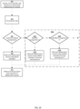
- Figure 9 shows an example of a method for receiving data from a controller and updating a game state of a game.
- the method comprises steps of:
- the "default" arrangement refers to an arrangement in which the insert 500 is not installed
- the “modified” arrangement refers to an arrangement in which the insert 500 is installed.
- the determination 906 of whether the joystick has the default arrangement or the modified arrangement may be based on a user input (e.g. a selection from a menu), or it may be based on data received from a sensor in the controller (e.g. a sensor configured to detect when the insert is installed).
- Figure 10 shows another example of a method for receiving data from a controller and updating a game state of a game, in which the displacement amount can be calculated in dependence on which of multiple different modified arrangements is detected (e.g. these could be multiple different thicknesses of the insert 500).
- the method of Figure 10 includes all of the steps 902-912 of Figure 9 , with the following modifications: when it is determined 906 that the joystick does not have the default arrangement, it is determined 1002, 1006 which of two or more modified arrangements the joystick has. If it is determined 1002 that the joystick has modified arrangement 1, then a first modified calculation is applied 1004 to calculate the displacement amount. If it is determined 1006 that the joystick has modified arrangement 2, then a second modified calculation is applied 1008 to calculate the displacement amount.
- modified arrangement 2 may comprise a thicker insert 500, and hence modified calculation 2 may involve increasing the sensitivity of the joystick by a greater amount than in calculation 1.
- the sensitivity of the joystick can be increased in dependence on whether or not an insert is installed to the joystick.
- This in combination with the installation of the joystick, allows the range of motion of the joystick to be restricted while allowing more accurate control of a game state by moving the joystick. This provides a better experience for a user with joint mobility issues, by allowing a controller to be adapted to suit the capabilities of the user.
- the method of Figure 9 or Figure 10 may be applied by a computer or by an entertainment system.
- a computer may execute instructions of a computer program, which may cause the computer to perform either of the above methods.
- the computer program may also be stored on a computer-readable storage medium, which may be transitory or non-transitory.
- a conventional equivalent device may be implemented in the form of a computer program product comprising processor implementable instructions stored on a non-transitory machine-readable medium such as a floppy disk, optical disk, hard disk, solid state disk, ROM, PROM, RAM, flash memory or any combination of these or other storage media, or realised in hardware as an ASIC (application specific integrated circuit) or an FPGA (field programmable gate array) or other configurable circuit suitable to use in adapting the conventional equivalent device.
- a computer program may be transmitted via data signals on a network such as an Ethernet, a wireless network, the Internet, or any combination of these or other networks.
Landscapes
- Engineering & Computer Science (AREA)
- Multimedia (AREA)
- Human Computer Interaction (AREA)
- General Engineering & Computer Science (AREA)
- Theoretical Computer Science (AREA)
- Physics & Mathematics (AREA)
- General Physics & Mathematics (AREA)
- Position Input By Displaying (AREA)
- Mechanical Control Devices (AREA)
Abstract
A controller 80, an insert 500 for a controller 80, an entertainment system 200, a method for receiving data from a controller, and a computer program. The controller 80 comprises a joystick 84 and a casing 301 at least partially surrounding the joystick 84. The insert 500 comprises a first surface 602 and a second surface 604, wherein at least one of: the first surface 602 has shape that is complementary with a shape of at least part of a stem 306 of the joystick 84, and the second surface 604 has a shape which is complementary with a shape of at least part of the casing 301. The insert 500 is configured, when installed between the stem 306 and the casing 301, to limit a range of motion of the stem 306.
Description
- The present technique relates to the field of computer input devices and more particularly to an insert for a handheld controller employing one or more joysticks.
- Even with the recent advances in performance capture (i.e., tracking of a system user's motion to induce a corresponding effect on a displayed graphic), a handheld controller with a joystick (also referred to as a control stick, thumb stick or analogue stick) remains the most popular input device for the electronic game industry. In
Figure 1 , the DualSense ® controller 80 is illustrated as an example of a handheld controller. Such a controller typically has twohandle sections 81L,R and a central body 81C. Various controls are distributed over the controller, typically in local groups. Examples include a left button group 82L, which may comprise directional controls and/or one or more shoulder buttons, and similarlyright button group 82R, which comprise function controls and/or one or more shoulder buttons. The controller (typically in the central portion of the device) may also comprise one ormore system buttons 86, which typically cause interaction with an operating system of the entertainment device rather than with a game or other application currently running on it; such buttons may summon a system menu, or allow for recording or sharing of displayed content. Furthermore, the controller may comprise one or more other elements such as atouchpad 88, a light for optical tracking (not shown), a screen (not shown), haptic feedback elements (not shown), and the like. - The controller also includes left and/or
right joysticks 84L,R, which may optionally also be operable as buttons by pressing down on them. Eachjoystick 84L,R provides a two-dimensional input (X,Y) which may be used to induce a corresponding effect on a displayed graphic. Eachjoystick 84L, R - sometimes called an analogue stick or more generally a control stick - provides positional input to a computing platform based on the position of the protrusion relative to a mechanical "centre" position within the controller body. During use, a user's thumb (or other digit) typically rests on a top surface (which may be referred to as a thumb pad) of eachjoystick 84L,R and pressure applied by the thumb may change the displacement of thejoystick 84L,R relative to the centre position, which may serve as a reference position. A pivoting base of eachjoystick 84L,R may be coupled to two or more potentiometers housed within the controller body to provide a continuous electrical output proportional to the displacement of thejoystick 84L,R relative to the central reference position (hence, the term "analogue stick"). The controller shown inFigure 1 is an example of a controller comprising a joystick and a casing at least partially surrounding the joystick. - While the control afforded by the continuous nature of the
joystick 84L,R has made it a popular input means for handheld controllers (particularly for 3D games), thejoystick 84L,R is nevertheless limited to the provision of a continuous electrical output proportional to the displacement of the joystick. This can present issues for some uses, such as users with mobility issues (e.g. finger joint mobility issues, which may affect the thumbs). Users with such mobility issues may have a limited range of motion in their thumb(s), and hence may be unable to make use of the full range of motion of the joystick. For such users, dedicated "accessible" controllers can be provided, which can be designed to be easier to use for people with mobility issues. However, providing multiple different controller designs for users with varying abilities can be expensive, and hence such controllers can be prohibitively expensive for users with mobility issues. - The present invention seeks to mitigate or alleviate this problem.
- In a first example of the present technique, there is provided an insert for a controller, as defined in
claim 1. - In another example of the present technique, there is provided a controller as defined in claim 10.
- In another example of the present technique, there is provided an entertainment device as defined in claim 12.
- In another example of the present technique, there is provided a method for receiving data from a controller and updating a game state of a game, as defined in claim 13.
- In another example of the present technique, there is provided a computer program as defined in claim 14.
- In another example of the present technique there is provided a computer-readable storage medium as defined in claim 15.
- Further respective aspects and features of the invention are defined in the appended claims.
- Embodiments of the present invention will now be described by way of example with reference to the accompanying drawings, in which:
-
Figure 1 is an example of a handheld controller; -
Figure 2 is an example of an entertainment system; -
Figure 3 is an example of a joystick; -
Figures 4 to 8 are examples of joysticks fitted with inserts; and -
Figures 9 and10 are flow diagrams showing example methods of receiving data from a controller and updating a game state of a game. - For clarity of illustration, elements illustrated in the figures have not necessarily been drawn to scale. Further, where considered appropriate, reference numerals have been repeated among the figures to indicate corresponding or analogous elements.
- The terms "coupled" and "connected," along with their derivatives, may be used herein to describe structural relationships between components of the apparatus for performing the operations herein. It should be understood that these terms are not intended as synonyms for each other. Rather, in particular embodiments, "connected" is used to indicate that two or more elements are in direct physical or electrical contact with each other while "coupled" is used to indicate two or more elements are in either direct or indirect (with other intervening elements between them) physical or electrical contact with each other, and/or that the two or more elements co-operate or communicate with each other (e.g., as in a cause an effect relationship).
- In the following description, a number of specific details are presented in order to provide a thorough understanding of the embodiments of the present invention. It will be apparent, however, to a person skilled in the art that these specific details need not be employed to practice the present invention. Conversely, specific details known to the person skilled in the art are omitted for the purposes of clarity where appropriate.
- Referring to
Figure 2 , an example of anentertainment system 200 is a computer or console such as the Sony ® PlayStation 5 ® (PS5). - The
entertainment system 200 comprises acentral processor 220. This may be a single or multi core processor, for example comprising eight cores as in the PS5. The entertainment system also comprises a graphical processing unit or GPU 30. The GPU can be physically separate to the CPU, or integrated with the CPU as a system on a chip (SoC) as in the PS5. - The entertainment device also comprises
RAM 240, and may either have separate RAM for each of the CPU and GPU, or shared RAM as in the PS5. The or each RAM can be physically separate, or integrated as part of an SoC as in the PS5. Further storage is provided by adisk 250, either as an external or internal hard drive, or as an external solid state drive, or an internal solid state drive as in the PS5. - The entertainment device may transmit or receive data via one or more data ports 260 (e.g. receiver circuitry), such as a USB port, Ethernet ® port, WiFi ® port, Bluetooth ® port or similar, as appropriate. It may also optionally receive data via an
optical drive 270. - Interaction with the system is typically provided using one or more handheld controllers 280, such as the DualSense ® controller in the case of the PS5 (as illustrated in
Figure 1 ). - Audio/visual outputs from the entertainment device are typically provided through one or more A/V ports 290, or through one or more of the wired or wireless data ports 260.
- Where components are not integrated, they may be connected as appropriate either by a dedicated data link or via a
bus 292. - An example of a device for displaying images output by the entertainment system is a head mounted display 'HMD' 294, worn by a
user 296. - It will be appreciated that an entertainment system is just one example of a system with which a user may interact using a joystick. Moreover, while the above description describes joysticks being controlled by a user's thumb this is just one example - for example, another digit (e.g. another finger) could be used, or the joystick may instead be configured to be gripped by a user's entire hand.
- As noted above, a handheld controller comprising one or
more joysticks 84 may provide a means for interacting with anentertainment system 200.Figure 3 shows an example of a joystick which may be provided in such a handheld controller. When using a handheld controller including ajoystick 84, the force applied by the user's thumb may frequently displace thejoystick 84, causing a surface of thejoystick 84 to contact a surface of thecontroller casing 301.Figure 3 illustrates thejoystick 84 when the user's thumb applies a force to athumb pad 304 causing the joystick to reach a displacement limit θ where astem 306 of thejoystick 84 contacts thecasing 301 of the controller (e.g. this could be a part of the body of a handheld controller within which the joystick is provided). - Although not shown in
Figure 3 , it will be appreciated that one or more sensors (e.g. pressure sensors and/or displacement sensors) may be provided - either as part of thejoystick 84 itself (e.g. on or in thestem 306, thethumb pad 304 or a pivoting section 308) or within the controller body (e.g. in or on the casing 301) - to detect the displacement of thejoystick 84 relative to a centre position α and/or a pressure applied to thejoystick 84. Information obtained from these sensors can then be used to control - for example - a game state of a game. For example, an entertainment system may receive data from the one or more sensors indicative of a displacement and/or pressure measured by the sensors, and may use this data to control the game state. - As explained above, a user with joint mobility issues in their thumb(s) may have difficulty using a
joystick 84 if, for example, their joint mobility issues reduce the range of motion of their thumbs. For example, some users may be unable to push thejoystick 84 all the way to the displacement limit θ, or be unable to do so without incurring discomfort. This may limit the users' ability to control a computer or gaming system using thejoystick 84. - To address this issue, one could increase the sensitivity of the
joystick 84 so that smaller movements of thejoystick 84 are interpreted, by the gaming system or computer, as larger displacement amounts. However, it can be difficult to control ajoystick 84 with a high sensitivity. Hence, the present technique provides an insert for a controller which, when installed, limits the range of motion of thejoystick 84 so that a user can more accurately control thejoystick 84 when the sensitivity is increased. -
Figures 4A and 4B show examples of how aninsert 500 can be installed between thestem 306 of ajoystick 84 and thecasing 301 of the controller, to limit a range of motion of ajoystick 84. InFigure 4A , theinsert 500A is installed around thestem 306, whereas inFigure 4B , theinsert 500B is installed around thecasing 301. In both examples, the presence of theinsert 500 reduces the displacement limit of thejoystick 84 from θ to φ. Accordingly, by installing theinsert 500 and increasing the sensitivity of thejoystick 84, it is possible to adapt ajoystick 84 to better suit the abilities of a user with joint mobility issues. It will also be appreciated that a combination of both types of insert may be used together, with each being thinner than if used alone for the same degree of angular restriction; this may be helpful for example to increase resilience of the insert around the casing, and flexibility for mounting an insert on the stem. -
Figures 5A-D and6A-D show examples of theinsert 500 for a controller. In all of the examples, theinsert 500 is installed between thestem 306 of the joystick and thecasing 301 of the controller (for clarity, the thumb pad is not shown). Each of theinserts 500 has a first (inner)surface 602 and a second (outer)surface 604. - In the examples shown in
Figures 5A to 5D , theinsert 500 is installed in contact with thestem 306 of the joystick - in particular, thefirst surface 602 of eachinsert 500 is in contact with thestep 306. Hence, thefirst surface 602 of each of theinserts 500 has the same radius of curvature as an outer surface of thestem 306. For example,Figure 5A shows an example where theinsert 500 is annular (e.g. ring-shaped), whileFigures 5B and 5C show examples where theinsert 500 is an annulus sector (e.g. an incomplete ring-shape) -Figure 5C shows an example where theinsert 500 may be made up of multiple (in this case two) pieces; in this case the pieces may rely on adhesion to attach to the stem, rather than clipping on or acting as a sleeve (though in these latter cases optionally adhesion may also be used). Forming the inserts so that their cross sections are annuli or annuli sector can be a particularly advantageous implementation, since an insert with this shape may be able to withstand greater forces than other shapes, hence allowing the insert to be used for a longer period of time.Figure 5D shows an example where theinsert 500 comprises aring 602 forming the first surface, and four protrusions connected to the ring. -
Figures 6A to 6D show examples of inserts which are installed in contact with thecasing 301 of the controller, thesecond surface 604 of each of theinserts 500 having the same radius of curvature as an inner surface of thecasing 301, such that thesecond surface 604 of each insert 500 - when installed - is in contact with thecasing 301. For example,Figure 6A shows an example where theinsert 500 is annular (e.g. ring-shaped), whileFigures 6B and 6C show examples where theinsert 500 is an annulus sector (e.g. an incomplete ring-shape), and again may optionally rely on adhesion.Figure 6D shows an example where theinsert 500 comprises aring 604 forming the second surface, and four protrusions connected to the ring. - In any of the examples shown in
Figures 5A-D and6A-D , theinsert 500 can be made of a deformable material (e.g. a material which deforms when a pressure is applied to it). The material may also be elastic, allowing it to be stretched in order to easily install theinsert 500 in the controller. For example, using an elastic material would enable anannular insert 500 as shown inFigure 5A orFigure 6A to be stretched over the thumb pad of the joystick to install it. Similarly, using an elastic material would allow aninsert 500 in the shape of an annulus sector as shown inFigures 6B and7B to be stretched around thestem 306. - Alternatively, the insert can be made of a non-deformable material (e.g. a material which does not deform - or which only deforms by a negligible amount - when a pressure is applied to it).
- If a non-deformable material is used and the
insert 500 is an annulus arranged to fit to the joystick stem 306 (e.g. as shown inFigure 6A ), the insert may be made up of two or more parts connected via one ormore hinges 700 as shown inFigure 7A , to enable the insert to be installed. The annulus sector ofFigure 6B could also be made up of two or more hinged sections; alternatively, the non-deformable material may be able to bend/deform just enough to allow theinsert 500 to be opened and placed around the joystick. - Any of the
inserts 500 shown inFigures 6A-D may be configured to be installed in a push-fit manner (e.g. they may be shaped such that they exactly fit into thecasing 301 of the controller, allowing them to be pushed into place and held in place by the friction between theouter surface 604 and the casing, as well as by the pressure applied by theinsert 500 to the casing). In addition, as shown inFigure 7B , eachinsert 500 may comprise alip 702 along itsouter edge 604, to fit over the top of thecasing 301 and hold the insert more firmly in place. - The
insert 500 shown inFigure 6C may be made of any deformable or non-deformable material. The inserts inFigures 6A and 6B can also be made of either a deformable or non-deformable material. If the thumb pad of the joystick is larger (e.g. has a larger diameter) than the diameter of theinner surface 602 of the insert, a deformable material allows theinsert 500 to be stretched around the joystick and pushed into place in the controller. However, if theinsert 500 comprises anon-deformable material 602 then, unless the thumb pad has a smaller diameter than the inner surface, the inserts when inFigures 6A and 6B may be formed of two pieces as shown inFigure 7C . - The material used to make the
insert 500 is not particularly limited. For example, any form of plastic, silicone, rubber and/or elastic may be used. - The thickness of the insert 500 (e.g. the distance between the
first surface 602 and the second surface 604) can be varied in order to vary the degree by which the motion of thejoystick 84 is restricted. In addition, as noted previously it will be appreciated that it may also be possible to install multiple inserts - e.g. theinserts 500A,B shown in bothFigure 4A and Figure 4B - in the same controller, to further limit the range of motion of the joystick. - In the examples of
Figures 5A-D and6A-D , theinsert 500 is arranged, when installed, to occupy (e.g. fill) part but not all of the space between thestem 306 and thecasing 301. In particular, the inserts shown inFigures 5A-D and 6A-D are each arranged so that, when they are installed, they radially fill only part of the space (e.g. the thickness of each insert is less than the distance between the stem of the joystick and the inner surface of the casing). However, in the example shown inFigure 8 , theinsert 500 is arranged to completely fill the space between thestem 306 and thecasing 301. In this example, thefirst surface 602 of each of theinserts 500 has the same radius of curvature as an outer surface of thestem 306, and thesecond surface 604 of each of theinserts 500 has the same radius of curvature as an inner surface of thecasing 301. When installed, theinsert 500 shown inFigure 8 is in contact with both thestem 306 and thecasing 301. - In the example of
Figure 8 , theinsert 500 is made of a deformable material, to enable thejoystick 84 to move. However, the presence of the deformable material between thestem 306 and thecasing 301 increases the resistance to the motion of thejoystick 84 so that the range of motion of the joystick is restricted. To vary the degree to which the range of motion is restricted, the material can be varied - for example, a less deformable material can be used to further restrict the range of motion. It will also be appreciated that the deformable material may be bonded to a hard material to provide a strong attachment to either the casing or the stem, and optionally depending on the radial extent of the hard material, also to provide a reduced or further reduced total range of movement. -
Figure 9 shows an example of a method for receiving data from a controller and updating a game state of a game. For example, the method comprises steps of: - receiving 902, from the controller, data indicative of a determined displacement of a joystick;
- processing 904 the game state of the game;
- determining 906 whether the joystick has a default arrangement or a modified arrangement;
- determining 905 a displacement amount of the joystick based on the data indicative of the determined displacement and whether the joystick has a default arrangement or a modified arrangement - for example, a modified
calculation 910 is used if it is determined that the joystick has the modified arrangement, whereas adefault calculation 908 is used if the joystick has the default arrangement; and - updating 912 the processing of the game state of the game responsive to the displacement amount of the joystick.
- In this example, the "default" arrangement refers to an arrangement in which the
insert 500 is not installed, while the "modified" arrangement refers to an arrangement in which theinsert 500 is installed. Thedetermination 906 of whether the joystick has the default arrangement or the modified arrangement may be based on a user input (e.g. a selection from a menu), or it may be based on data received from a sensor in the controller (e.g. a sensor configured to detect when the insert is installed). -
Figure 10 shows another example of a method for receiving data from a controller and updating a game state of a game, in which the displacement amount can be calculated in dependence on which of multiple different modified arrangements is detected (e.g. these could be multiple different thicknesses of the insert 500). - The method of
Figure 10 includes all of the steps 902-912 ofFigure 9 , with the following modifications: when it is determined 906 that the joystick does not have the default arrangement, it is determined 1002, 1006 which of two or more modified arrangements the joystick has. If it is determined 1002 that the joystick has modifiedarrangement 1, then a first modified calculation is applied 1004 to calculate the displacement amount. If it is determined 1006 that the joystick has modifiedarrangement 2, then a second modified calculation is applied 1008 to calculate the displacement amount. - In a particular example, modified
arrangement 2 may comprise athicker insert 500, and hence modifiedcalculation 2 may involve increasing the sensitivity of the joystick by a greater amount than incalculation 1. - Accordingly, by applying the method of
Figure 9 orFigure 10 , the sensitivity of the joystick can be increased in dependence on whether or not an insert is installed to the joystick. This, in combination with the installation of the joystick, allows the range of motion of the joystick to be restricted while allowing more accurate control of a game state by moving the joystick. This provides a better experience for a user with joint mobility issues, by allowing a controller to be adapted to suit the capabilities of the user. - The method of
Figure 9 orFigure 10 may be applied by a computer or by an entertainment system. For example, a computer may execute instructions of a computer program, which may cause the computer to perform either of the above methods. The computer program may also be stored on a computer-readable storage medium, which may be transitory or non-transitory. - Hence it will be appreciated that the above methods may be carried out on conventional hardware suitably adapted as applicable by software instruction or by the inclusion or substitution of dedicated hardware.
- Thus the required adaptation to existing parts of a conventional equivalent device may be implemented in the form of a computer program product comprising processor implementable instructions stored on a non-transitory machine-readable medium such as a floppy disk, optical disk, hard disk, solid state disk, ROM, PROM, RAM, flash memory or any combination of these or other storage media, or realised in hardware as an ASIC (application specific integrated circuit) or an FPGA (field programmable gate array) or other configurable circuit suitable to use in adapting the conventional equivalent device. Separately, such a computer program may be transmitted via data signals on a network such as an Ethernet, a wireless network, the Internet, or any combination of these or other networks.
Claims (15)
- An insert for a controller, the controller comprising a joystick and a casing at least partially surrounding the joystick, wherein the insert comprises:a first surface and a second surface, wherein at least one of:the first surface has shape that is complementary with a shape of at least part of a stem of the joystick; andthe second surface has a shape which is complementary with a shape of at least part of the casing,wherein the insert is configured, when installed between the stem and the casing, to limit a range of motion of the stem.
- The insert of claim 1, wherein at least one of:the first surface comprises a curved surface with a radius of curvature corresponding to a radius of curvature of the at least part of the stem; andthe second surface comprises a curved surface with a radius of curvature corresponding to a radius of curvature of the at least part of the casing.
- The insert of claim 1 or claim 2, wherein
the insert is configured, when installed between the stem and the casing, to fill at least part of a space between the stem and the casing in a radial direction. - The insert of any preceding claim, wherein:the insert is shaped as an annulus or an annulus sector; andthe first surface comprises an inner surface of the annulus or annulus sector and the second surface comprises an outer surface of the annulus or annulus sector.
- The insert of any preceding claim, wherein
the insert is formed of a deformable material configured to deform in response to a force being applied to the deformable material. - The insert of claim 5, wherein
the deformable material is elastic. - The insert of claim 5 or claim 6, wherein
the insert is configured, when installed between the stem and the casing, to fully fill a space between the stem and the casing. - The insert of any of claims 1 to 4, wherein
the insert is formed of a substantially non-deformable material configured to resist deforming in response to a force being applied to the substantially non-deformable material. - The inset of claim 8, wherein
the insert is configured, when installed between the stem and the casing, to partially fill a space between the stem and the casing in a radial direction and to leave at least part of the space between the stem and the casing in the radial direction unfilled by the insert. - A controller comprising:a joystick and a casing at least partially surrounding the joystick; andthe insert of any preceding claim,wherein the insert is installed between the stem and the casing.
- The controller of claim 10, comprising
at least one sensor to detect that the insert is installed. - An entertainment device comprising:receiver circuitry to receive, from a controller, data indicative of a determined displacement of a joystick; andprocessing circuitry to:process a game state of a game,determine whether the joystick has a default arrangement or a modified arrangement;determine a displacement amount of the joystick based on the data indicative of the determined displacement and whether the joystick has the default arrangement or the modified arrangement; andupdate the processing of the game state of the game responsive to the displacement amount of the joystick.
- A method for receiving data from a controller and updating a game state of a game, the method comprising:receiving, from the controller, data indicative of a determined displacement of a joystick;processing the game state of the game;determining whether the joystick has a default arrangement or a modified arrangement;determining a displacement amount of the joystick based on the data indicative of the determined displacement and whether the joystick has a default arrangement or a modified arrangement; andupdating the processing of the game state of the game responsive to the displacement amount of the joystick.
- A computer program comprising instructions which, when executed on a computer, cause the computer to perform the method of claim 13.
- A computer-readable storage medium storing the computer program of claim 14.
Applications Claiming Priority (1)
| Application Number | Priority Date | Filing Date | Title |
|---|---|---|---|
| GB2209508.7A GB2620152A (en) | 2022-06-29 | 2022-06-29 | Insert for a controller |
Publications (1)
| Publication Number | Publication Date |
|---|---|
| EP4299151A1 true EP4299151A1 (en) | 2024-01-03 |
Family
ID=82705679
Family Applications (1)
| Application Number | Title | Priority Date | Filing Date |
|---|---|---|---|
| EP23179435.5A Pending EP4299151A1 (en) | 2022-06-29 | 2023-06-15 | Insert for a controller |
Country Status (3)
| Country | Link |
|---|---|
| US (1) | US20240001225A1 (en) |
| EP (1) | EP4299151A1 (en) |
| GB (1) | GB2620152A (en) |
Families Citing this family (1)
| Publication number | Priority date | Publication date | Assignee | Title |
|---|---|---|---|---|
| DE102023119430B3 (en) * | 2023-07-23 | 2024-09-26 | Gaimx Gmbh | Resistance element for a handheld controller for controlling computer games |
Citations (6)
| Publication number | Priority date | Publication date | Assignee | Title |
|---|---|---|---|---|
| WO2016191011A1 (en) * | 2015-05-27 | 2016-12-01 | Microsoft Technology Licensing, Llc | Thumbstick interface ring for game controller |
| WO2018093328A1 (en) * | 2016-11-21 | 2018-05-24 | Razer (Asia-Pacific) Pte. Ltd. | Game controllers and methods for controlling a game controller |
| US11110345B2 (en) * | 2015-01-09 | 2021-09-07 | Ironburg Inventions Limited | Controller for a games console |
| US20210354030A1 (en) * | 2018-10-25 | 2021-11-18 | Nacon | Game controller comprising at least one removable adjusting element allowing adjustment of the stop angle of a pivoting control member of the controller |
| US20210379488A1 (en) * | 2018-10-25 | 2021-12-09 | Nacon | Game controller comprising at least one pivoting control member with a modifiable stop angle |
| CA3141811A1 (en) * | 2020-11-23 | 2022-05-23 | Collective Minds Gaming Co. Ltd. | System and method for generating a scaled control signal for a video game console using a video game controller, and a stop member to limit displacement of a control stick |
Family Cites Families (6)
| Publication number | Priority date | Publication date | Assignee | Title |
|---|---|---|---|---|
| US4469330A (en) * | 1982-01-07 | 1984-09-04 | Atari, Inc. | Controller unit for video game |
| JPH0973363A (en) * | 1995-09-06 | 1997-03-18 | Sega Enterp Ltd | Operation input device |
| US8648804B1 (en) * | 2011-08-11 | 2014-02-11 | Timothy Paul Roberts | Joystick apparatus |
| US20160346680A1 (en) * | 2015-05-27 | 2016-12-01 | Microsoft Technology Licensing, Llc | Game controller with thumbstick interface ring |
| US10556174B2 (en) * | 2017-10-25 | 2020-02-11 | Microsoft Technology Licensing, Llc | Calibration bias for control mechanisms in user input devices |
| WO2020217374A1 (en) * | 2019-04-25 | 2020-10-29 | 株式会社ホリ | Controller |
-
2022
- 2022-06-29 GB GB2209508.7A patent/GB2620152A/en active Pending
-
2023
- 2023-06-15 EP EP23179435.5A patent/EP4299151A1/en active Pending
- 2023-06-22 US US18/339,384 patent/US20240001225A1/en active Pending
Patent Citations (6)
| Publication number | Priority date | Publication date | Assignee | Title |
|---|---|---|---|---|
| US11110345B2 (en) * | 2015-01-09 | 2021-09-07 | Ironburg Inventions Limited | Controller for a games console |
| WO2016191011A1 (en) * | 2015-05-27 | 2016-12-01 | Microsoft Technology Licensing, Llc | Thumbstick interface ring for game controller |
| WO2018093328A1 (en) * | 2016-11-21 | 2018-05-24 | Razer (Asia-Pacific) Pte. Ltd. | Game controllers and methods for controlling a game controller |
| US20210354030A1 (en) * | 2018-10-25 | 2021-11-18 | Nacon | Game controller comprising at least one removable adjusting element allowing adjustment of the stop angle of a pivoting control member of the controller |
| US20210379488A1 (en) * | 2018-10-25 | 2021-12-09 | Nacon | Game controller comprising at least one pivoting control member with a modifiable stop angle |
| CA3141811A1 (en) * | 2020-11-23 | 2022-05-23 | Collective Minds Gaming Co. Ltd. | System and method for generating a scaled control signal for a video game console using a video game controller, and a stop member to limit displacement of a control stick |
Also Published As
| Publication number | Publication date |
|---|---|
| US20240001225A1 (en) | 2024-01-04 |
| GB2620152A (en) | 2024-01-03 |
| GB202209508D0 (en) | 2022-08-10 |
Similar Documents
| Publication | Publication Date | Title |
|---|---|---|
| US9996153B1 (en) | Haptic interaction method, tool and system | |
| JP7145889B2 (en) | Input method and device | |
| AU2022232901B2 (en) | Virtualized physical controller | |
| US20200026354A1 (en) | Adaptive haptic effect rendering based on dynamic system identification | |
| CN113825548A (en) | Using the presence of a finger to activate a motion control function of a hand-held controller | |
| US11231784B2 (en) | Stylus with shear force feedback | |
| EP3009914A1 (en) | Haptically-enabled deformable device with rigid component | |
| JP2008203911A (en) | Pointing device and computer | |
| US20250238083A1 (en) | Device for intuitive dexterous touch and feel interaction in virtual worlds | |
| US20240001225A1 (en) | Insert for a controller | |
| US20180101244A1 (en) | Virtual Reality Input System and Methods | |
| CN112237736A (en) | Using touch sensing to make a trackball behave like a joystick | |
| AU2022234308A1 (en) | Infinite drag and swipe for virtual controller | |
| US20200387246A1 (en) | Systems and methods for particle jamming haptic feedback | |
| US20120013487A1 (en) | Revolving Control Device with a Displacement Sensor without Contact Points | |
| JP2019522829A (en) | Expression of haptic effect by intra device mixing | |
| CN111176467A (en) | Pressure induction mouse | |
| WO2025254792A1 (en) | Devices and virtual reality interfaces for gaming | |
| CN120417975A (en) | Dual control application and system for games | |
| HK40017095A (en) | Haptic interaction method and system | |
| HK40017095B (en) | Haptic interaction method and system |
Legal Events
| Date | Code | Title | Description |
|---|---|---|---|
| PUAI | Public reference made under article 153(3) epc to a published international application that has entered the european phase |
Free format text: ORIGINAL CODE: 0009012 |
|
| STAA | Information on the status of an ep patent application or granted ep patent |
Free format text: STATUS: REQUEST FOR EXAMINATION WAS MADE |
|
| 17P | Request for examination filed |
Effective date: 20230701 |
|
| AK | Designated contracting states |
Kind code of ref document: A1 Designated state(s): AL AT BE BG CH CY CZ DE DK EE ES FI FR GB GR HR HU IE IS IT LI LT LU LV MC ME MK MT NL NO PL PT RO RS SE SI SK SM TR |