EP4297886B1 - A plastic connector and air cleaner system with air cleaners in parallel connection using the same - Google Patents
A plastic connector and air cleaner system with air cleaners in parallel connection using the same Download PDFInfo
- Publication number
- EP4297886B1 EP4297886B1 EP22710862.8A EP22710862A EP4297886B1 EP 4297886 B1 EP4297886 B1 EP 4297886B1 EP 22710862 A EP22710862 A EP 22710862A EP 4297886 B1 EP4297886 B1 EP 4297886B1
- Authority
- EP
- European Patent Office
- Prior art keywords
- fastener
- connector
- plastic
- plastic connector
- air
- Prior art date
- Legal status (The legal status is an assumption and is not a legal conclusion. Google has not performed a legal analysis and makes no representation as to the accuracy of the status listed.)
- Active
Links
Images



Classifications
-
- F—MECHANICAL ENGINEERING; LIGHTING; HEATING; WEAPONS; BLASTING
- F02—COMBUSTION ENGINES; HOT-GAS OR COMBUSTION-PRODUCT ENGINE PLANTS
- F02M—SUPPLYING COMBUSTION ENGINES IN GENERAL WITH COMBUSTIBLE MIXTURES OR CONSTITUENTS THEREOF
- F02M35/00—Combustion-air cleaners, air intakes, intake silencers, or induction systems specially adapted for, or arranged on, internal-combustion engines
- F02M35/02—Air cleaners
- F02M35/024—Air cleaners using filters, e.g. moistened
- F02M35/02416—Fixing, mounting, supporting or arranging filter elements; Filter element cartridges
-
- F—MECHANICAL ENGINEERING; LIGHTING; HEATING; WEAPONS; BLASTING
- F02—COMBUSTION ENGINES; HOT-GAS OR COMBUSTION-PRODUCT ENGINE PLANTS
- F02M—SUPPLYING COMBUSTION ENGINES IN GENERAL WITH COMBUSTIBLE MIXTURES OR CONSTITUENTS THEREOF
- F02M35/00—Combustion-air cleaners, air intakes, intake silencers, or induction systems specially adapted for, or arranged on, internal-combustion engines
- F02M35/02—Air cleaners
- F02M35/0201—Housings; Casings; Frame constructions; Lids; Manufacturing or assembling thereof
-
- F—MECHANICAL ENGINEERING; LIGHTING; HEATING; WEAPONS; BLASTING
- F02—COMBUSTION ENGINES; HOT-GAS OR COMBUSTION-PRODUCT ENGINE PLANTS
- F02M—SUPPLYING COMBUSTION ENGINES IN GENERAL WITH COMBUSTIBLE MIXTURES OR CONSTITUENTS THEREOF
- F02M35/00—Combustion-air cleaners, air intakes, intake silencers, or induction systems specially adapted for, or arranged on, internal-combustion engines
- F02M35/02—Air cleaners
- F02M35/0201—Housings; Casings; Frame constructions; Lids; Manufacturing or assembling thereof
- F02M35/0204—Housings; Casings; Frame constructions; Lids; Manufacturing or assembling thereof for connecting or joining to other devices, e.g. pipes
-
- F—MECHANICAL ENGINEERING; LIGHTING; HEATING; WEAPONS; BLASTING
- F02—COMBUSTION ENGINES; HOT-GAS OR COMBUSTION-PRODUCT ENGINE PLANTS
- F02M—SUPPLYING COMBUSTION ENGINES IN GENERAL WITH COMBUSTIBLE MIXTURES OR CONSTITUENTS THEREOF
- F02M35/00—Combustion-air cleaners, air intakes, intake silencers, or induction systems specially adapted for, or arranged on, internal-combustion engines
- F02M35/02—Air cleaners
- F02M35/0201—Housings; Casings; Frame constructions; Lids; Manufacturing or assembling thereof
- F02M35/0209—Housings; Casings; Frame constructions; Lids; Manufacturing or assembling thereof comprising flexible, resilient, movable or rotatable elements, e.g. with vibrating or contracting movements; Springs; Valves; Flaps
-
- F—MECHANICAL ENGINEERING; LIGHTING; HEATING; WEAPONS; BLASTING
- F02—COMBUSTION ENGINES; HOT-GAS OR COMBUSTION-PRODUCT ENGINE PLANTS
- F02M—SUPPLYING COMBUSTION ENGINES IN GENERAL WITH COMBUSTIBLE MIXTURES OR CONSTITUENTS THEREOF
- F02M35/00—Combustion-air cleaners, air intakes, intake silencers, or induction systems specially adapted for, or arranged on, internal-combustion engines
- F02M35/02—Air cleaners
- F02M35/0212—Multiple cleaners
- F02M35/0215—Multiple cleaners arranged in parallel
-
- F—MECHANICAL ENGINEERING; LIGHTING; HEATING; WEAPONS; BLASTING
- F02—COMBUSTION ENGINES; HOT-GAS OR COMBUSTION-PRODUCT ENGINE PLANTS
- F02M—SUPPLYING COMBUSTION ENGINES IN GENERAL WITH COMBUSTIBLE MIXTURES OR CONSTITUENTS THEREOF
- F02M35/00—Combustion-air cleaners, air intakes, intake silencers, or induction systems specially adapted for, or arranged on, internal-combustion engines
- F02M35/02—Air cleaners
- F02M35/04—Air cleaners specially arranged with respect to engine, to intake system or specially adapted to vehicle; Mounting thereon ; Combinations with other devices
-
- F—MECHANICAL ENGINEERING; LIGHTING; HEATING; WEAPONS; BLASTING
- F16—ENGINEERING ELEMENTS AND UNITS; GENERAL MEASURES FOR PRODUCING AND MAINTAINING EFFECTIVE FUNCTIONING OF MACHINES OR INSTALLATIONS; THERMAL INSULATION IN GENERAL
- F16B—DEVICES FOR FASTENING OR SECURING CONSTRUCTIONAL ELEMENTS OR MACHINE PARTS TOGETHER, e.g. NAILS, BOLTS, CIRCLIPS, CLAMPS, CLIPS OR WEDGES; JOINTS OR JOINTING
- F16B2/00—Friction-grip releasable fastenings
- F16B2/02—Clamps, i.e. with gripping action effected by positive means other than the inherent resistance to deformation of the material of the fastening
- F16B2/04—Clamps, i.e. with gripping action effected by positive means other than the inherent resistance to deformation of the material of the fastening internal, i.e. with spreading action
-
- F—MECHANICAL ENGINEERING; LIGHTING; HEATING; WEAPONS; BLASTING
- F16—ENGINEERING ELEMENTS AND UNITS; GENERAL MEASURES FOR PRODUCING AND MAINTAINING EFFECTIVE FUNCTIONING OF MACHINES OR INSTALLATIONS; THERMAL INSULATION IN GENERAL
- F16L—PIPES; JOINTS OR FITTINGS FOR PIPES; SUPPORTS FOR PIPES, CABLES OR PROTECTIVE TUBING; MEANS FOR THERMAL INSULATION IN GENERAL
- F16L41/00—Branching pipes; Joining pipes to walls
- F16L41/02—Branch units, e.g. made in one piece, welded, riveted
- F16L41/023—Y- pieces
Definitions
- the present invention relates to air filtration field, especially relates to a plastic connector for dual air cleaners and an air cleaner system with air cleaners in parallel connection bonded with the plastic connector.
- Air cleaners are used to filter various impurities in the air, to ensure clean air into the engine.
- air flow rate of the air cleaner needs to match with air flow rate of the engine.
- the air flow rate of the air cleaner is relatively small while the air flow rate of the engine is relatively large, causing the two not matching with each other.
- one solution used is to have several (e.g., two (2)) air cleaners with smaller air flow rate in parallel connection as one unitary product, to match with the engine having larger air flow rate.
- Such solution is widely used in the air cleaner industry due to its flexibility and low costs.
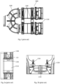
- Figs. 1-2b show a dual air cleaner system that is currently used.
- the air cleaner system 1000 includes two air cleaners 1100 in parallel connection, a Y-shaped outlet duct 1200 connected with one end of each air cleaners 1100, and a connector 1300 securing the two air cleaners 1100 together.
- two ports of the Y-shaped outlet duct 1200 are connected to respective outlets of the two air cleaners 1100, and the third one leads to the engine.
- a metal connector 1300 composed of a U-shaped metal plate 1310, metal screws 1320 and metal nuts 1330 is adopted to bond the two air cleaners 1100 together.
- an objective of the present invention is to provide a connector for securing a plurality of air cleaners together, to address the issues in connection with high costs, complex installation and less durability of air cleaners due to rigid connection.
- the present invention adopts the following technical solutions.
- the present invention provides a plastic connector for securing air cleaners in parallel connection, including a connector body and a fastener.
- the connector body has guide rails and frame legs; and the fastener has openings and fastener arms.
- the openings of the fastener are in snap-fit with the guide rails of the connector body, to enable the connector body and the fastener assembled into the plastic connector.
- the fastener can slide along the guide rails under force.
- the openings are in square shape, to match with a cross-section of the guide rails.
- the fastener is elastic.
- the connector body further comprises body position limiters extending outwardly from the guide rails to prevent the fastener detaching from the connector body due to deformation.
- the body position limiter has a curvature that matches with a curvature of a curved side of the fastener, to prevent the fastener detaching from the connector body by pressing against the curved side of the fastener.
- the fastener further has fastener position limiters extending transversely at certain angle inside the fastener and located under the openings, to press against the guide rails when the plastic connector is pulled, to prevent the fastener arms from popping out of the mounting holes of the mounting bracket so that the plastic connector accidentally got loosened.
- the fastener has a pair of fastener position limiters extending transversely inside the fastener at certain angle in opposite directions from center of opposite sides of the fastener, respectively.
- the fastener arms extend outwardly from opposite sides along a short axis of the fastener, with a lead-in angle at an end of the fastener arm.
- the present invention provides an air cleaner system with air cleaners in parallel connection using a plurality of plastic connectors, including two or more air cleaners, a multi-branch outlet duct connected to an outlet end of respective air cleaners and any one of the foregoing plastic connector mounted onto mounting brackets.
- the fastener arms when the plastic connector is directly pressed into the mounting bracket by hand, the fastener arms, guided by the lead-in angle, insert into corresponding mounting holes on the mounting bracket, and the frame legs also insert into their corresponding mounting holes on the mounting bracket, so as to secure the air cleaners in parallel connection.
- the present invention adopts a two-piece plastic connector assembly to connect and secure air cleaners in parallel connection. Comparing with the existing method for securing dual air cleaners, such as by way of metal connectors, the present invention has advantages, including:
- the present invention relates to an air cleaner system with air cleaners in parallel connection using plastic connector(s) for bonding, comprising two or more air cleaners, an air outlet multi-branch tube and plastic connectors.
- Fig. 3 shows a dual air cleaner system. As shown, air outlet ends 21 of respective air cleaners 20 are in parallel connection through corresponding ports of an Y-shaped outlet duct 30, and the other port of the Y-shaped outlet duct 30 leads to an engine. In this embodiment, the Y-shaped outlet duct 30 is fixed to the air outlet end 21 of respective air cleaner 20 through a clamp 31 at the port.
- plastic connectors 10 provided between the two air cleaners 20.
- the plastic connectors 10 are installed on corresponding mounting bracket 40 of the air cleaner 20, respectively, for connecting and securing the two air cleaners 20. Number of the plastic connectors 10 used for the air cleaner system with air cleaners in parallel connection can be adjusted based on the size and shape of specific cleaners and operating condition, etc.
- the plastic connector 10 comprises a connector body 100 and a fastener 200, the two in snap-fit to constitute the connector assembly.
- the connector body 100 and the fastener 200 each are prepared by injection molding process.
- the connector body 100 can use nylon plus glass fiber material, while the fastener 200 can use POM (acetal resin) material.
- both of the connector body 100 and the fastener 200 can use PP (polypropylene) plus glass fiber material, to further reduce costs.
- the connector body 100 as shown in Fig. 5 , comprises guide rails 101, frame legs 102 and body position limiters 103, symmetrically positioned.
- the frame legs 102 are respectively located at two sides of the connector body 100. When pressing down the plastic connector 10, the frame legs 102 will be pushed into mounting holes of the mounting brackets.
- the fastener 200 is preferably in oblong shape, such as O shape, with certain elasticity (or flexibility), and can be deformed under pressure.
- the oblong/O shape exhibits a pair of generally parallel straight sides coupled with a pair of opposite curved sides, when no external force is applied.
- other shapes suitable for the present invention are also possible.
- the fastener 200 has openings 201 on the generally straight sides.
- four (4) openings 201 are shown, two on each side, symmetrically arranged along the short axis of the oblong fastener. Number of the openings 201 and distances therebetween match the guide rails 101 of the connector body 100.
- the openings 201 shown in this embodiment are in square shape, to facilitate holding the guide rails 101. It shall be noted that other shapes of the openings are also possible, as long as the shape of openings would match the shape of the guide rails 101 so that the guide rails can slide therethrough.
- the fastener 200 When the connector body 100 is in snap-fit with the fastener 200, the fastener 200 will deform to expand under the force, until the guide rails 101 of the connector body 100 snap into the openings 201 of the fastener 200.
- the guide rails 101 pass through the openings 201 (see Fig. 4a ), and the fastener 200 having the openings 201 can expand and contract along the guide rails 101 as force applies.
- Figs. 4b-4c For different views of the connector body 100 in snap-fit with the fastener 200.
- the connector body 100 further is provided with body position limiters 103 extending outwardly from the guide rails 101.
- the body position limiters 103 are generally round, as shown in Fig. 4c , the curvature of which approximately matches with that of the curved sides of the fastener 200.
- the body position limiters 103 press against the curved sides of the fastener 200 to prevent further deformation of the fastener 200, so as to prevent the fastener 200 unintentionally detaching from the connector body 100.
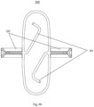
- the fastener 200 further has fastener arms 202, as shown in Figs. 6a-6b , which preferably extend outwardly along the short axis of the fastener 200.
- the fastener arm 202 has a lead-in angle 212 (see also Fig. 4b ).
- the lead-in angle is about 50 degrees.
- the lead-in angle can be in the range of 30°-60°.
- the fastener 200 further has fastener position limiters 203, extending transversely at certain angle inside the O-shaped fastener 200, and located under the openings 201.
- fastener position limiters 203 there are two fastener position limiters 203 extending in opposite directions from respective fastener arms 202 at an angle inside the O-shaped fastener 200.
- the fastener position limiters 203 will press against the guide rails 101 of the connector body 100 ( Fig. 8 ), to prevent the fastener arms 202 popping out of the mounting holes of the mounting bracket 40 so that the connector 10 would accidentally got loosened.
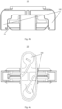
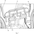
- Figs. 7-8 schematically show position of connector 10 relative to mounting bracket 40 before and after pushing down the connector 10 to lock onto the mounting bracket 40.
- Figs. 7-8 are shown in cross sectional views.
- the two air cleaners are placed side by side, and the connector 10 is push to lock by hand.
- the lead-in angle 212 on the elastic fastener 200 generates an inward component force on the mounting bracket 40, and the elastic fastener 200 contracts inwardly under such component force.
- the connector 10 continues to go downwardly under the push-down force, until the fastener arms 202 of the fastener 200 insert into the mounting holes of the mounting bracket 40 and the frame legs 102 of the connector body 100 also insert into their corresponding mounting holes of the mounting bracket 40.
- the two air cleaners are secured together. The whole operation process does not need any tool assistance.
Landscapes
- Engineering & Computer Science (AREA)
- General Engineering & Computer Science (AREA)
- Mechanical Engineering (AREA)
- Chemical & Material Sciences (AREA)
- Combustion & Propulsion (AREA)
- Manufacturing & Machinery (AREA)
- Quick-Acting Or Multi-Walled Pipe Joints (AREA)
- Insertion Pins And Rivets (AREA)
- Filtering Of Dispersed Particles In Gases (AREA)
- Connector Housings Or Holding Contact Members (AREA)
Description
- This application is being filed on February 25, 2022, as a
PCT International Patent application and claims the priority to Chinese Patent Application No. 202110213785.0, filed February 26, 2021 - The present invention relates to air filtration field, especially relates to a plastic connector for dual air cleaners and an air cleaner system with air cleaners in parallel connection bonded with the plastic connector.
- Air cleaners are used to filter various impurities in the air, to ensure clean air into the engine. Typically, air flow rate of the air cleaner needs to match with air flow rate of the engine. In practice, sometimes there will be occasions that the air flow rate of the air cleaner is relatively small while the air flow rate of the engine is relatively large, causing the two not matching with each other. To address the issue, one solution used is to have several (e.g., two (2)) air cleaners with smaller air flow rate in parallel connection as one unitary product, to match with the engine having larger air flow rate. Such solution is widely used in the air cleaner industry due to its flexibility and low costs.
- As an example,
Figs. 1-2b show a dual air cleaner system that is currently used. As shown in the drawings, theair cleaner system 1000 includes twoair cleaners 1100 in parallel connection, a Y-shaped outlet duct 1200 connected with one end of eachair cleaners 1100, and aconnector 1300 securing the twoair cleaners 1100 together. In the example, two ports of the Y-shaped outlet duct 1200 are connected to respective outlets of the twoair cleaners 1100, and the third one leads to the engine. Ametal connector 1300 composed of a U-shapedmetal plate 1310,metal screws 1320 andmetal nuts 1330 is adopted to bond the twoair cleaners 1100 together. - However, using metal connectors to bond the air cleaners is high in material costs and processing costs. Also, due to space constraint, assembly will become difficult. In addition, coupling of the metal connector and the air cleaner housing is rigid connection. As there is dimensional tolerance between the mounting surface of and the mounting bracket of the air cleaner, issues with respect to flatness and position accuracy between mounting point and mounting bracket of the air cleaner may occur, which may cause the air cleaners in parallel connection to have larger stress when installed, greatly impacting durability of the air cleaners.
- Therefore, there is always a need for a novel connector that can secure a plurality of air cleaners in parallel connection together. Such connector can reduce costs, facilitate installation, and have certain ability to self-adjust flatness and position between mounting point and mounting bracket of the air cleaner. A suitable connector is known from
CN110873010 A . Air filters with snap connectors are disclosed inUS8343247 B2 andUS2020/324237 A1 - In view of above, an objective of the present invention is to provide a connector for securing a plurality of air cleaners together, to address the issues in connection with high costs, complex installation and less durability of air cleaners due to rigid connection. The present invention adopts the following technical solutions.
- In one aspect, the present invention provides a plastic connector for securing air cleaners in parallel connection, including a connector body and a fastener. The connector body has guide rails and frame legs; and the fastener has openings and fastener arms. The openings of the fastener are in snap-fit with the guide rails of the connector body, to enable the connector body and the fastener assembled into the plastic connector. The fastener can slide along the guide rails under force.
- Preferably, the openings are in square shape, to match with a cross-section of the guide rails.
- The fastener is elastic.
- Preferably, the connector body further comprises body position limiters extending outwardly from the guide rails to prevent the fastener detaching from the connector body due to deformation.
- Preferably, the body position limiter has a curvature that matches with a curvature of a curved side of the fastener, to prevent the fastener detaching from the connector body by pressing against the curved side of the fastener.
- Preferably, the fastener further has fastener position limiters extending transversely at certain angle inside the fastener and located under the openings, to press against the guide rails when the plastic connector is pulled, to prevent the fastener arms from popping out of the mounting holes of the mounting bracket so that the plastic connector accidentally got loosened.
- Preferably, the fastener has a pair of fastener position limiters extending transversely inside the fastener at certain angle in opposite directions from center of opposite sides of the fastener, respectively.
- Preferably, the fastener arms extend outwardly from opposite sides along a short axis of the fastener, with a lead-in angle at an end of the fastener arm.
- In another aspect, the present invention provides an air cleaner system with air cleaners in parallel connection using a plurality of plastic connectors, including two or more air cleaners, a multi-branch outlet duct connected to an outlet end of respective air cleaners and any one of the foregoing plastic connector mounted onto mounting brackets.
- Preferably, when the plastic connector is directly pressed into the mounting bracket by hand, the fastener arms, guided by the lead-in angle, insert into corresponding mounting holes on the mounting bracket, and the frame legs also insert into their corresponding mounting holes on the mounting bracket, so as to secure the air cleaners in parallel connection.
- The present invention adopts a two-piece plastic connector assembly to connect and secure air cleaners in parallel connection. Comparing with the existing method for securing dual air cleaners, such as by way of metal connectors, the present invention has advantages, including:
- 1. low plastic costs and low injection molding process costs;
- 2. push-to-lock the connector by hand, which is efficient and convenient, with no tools needed; and
- 3. after the plastic connector is installed onto the mounting bracket of the air cleaners in parallel connection, due to flexibility of the plastics, the air cleaners in parallel connection can make minor adjustment, to self-adapt dimensional deviation between the mounting surface and the mounting bracket of the air cleaner, and to reduce installation stress of the air cleaners in parallel connection, which facilitates durability of the air cleaners.
- This summary is an overview of some of the teachings of the present application and is not intended to be an exclusive or exhaustive treatment of the present subject matter. Further details are found in the detailed description and appended claims. Other aspects will be apparent to persons skilled in the art upon reading and understanding the following detailed description and viewing the drawings that form a part thereof, each of which is not to be taken in a limiting sense. The scope herein is defined by the appended claims.
- In order to more clearly illustrate the technical solution of the embodiments of the present invention, brief description of the accompanying drawings is provided below. It would be obvious that the accompanying drawings described below are only some embodiments of the present invention. For ordinary technicians in the field, other embodiments can be obtained according to these embodiments without any creative work.
-
Fig. 1 is a schematic view of a dual air cleaner system using metal connectors in prior art. -
Figs. 2a-2b are enlarged views of the metal connector as shown inFig. 1 . -
Fig. 3 is a schematic view of a dual air cleaner system using plastic connectors according to one embodiment of the present invention. -
Figs. 4a-4c are schematic views of the plastic connector as shown inFig. 3 . -
Fig. 5 is a schematic view of the connector body of the plastic connector. -
Figs. 6a-6b are schematic views of the fastener of the plastic connector. -
Fig. 7 is a partial cross-sectional view of a dual air cleaner system before pushing down the plastic connector. -
Fig. 8 is a partial cross-sectional view of a dual air cleaner system after pushing down the plastic connector. - In order to elaborate the objectives, technical solutions and advantages of the present invention, detailed description is provided in connection with the accompanying drawings and embodiments. It should be understood that the specific embodiments described herein are only for illustrative and not restrictive.
- In an exemplary embodiment, the present invention relates to an air cleaner system with air cleaners in parallel connection using plastic connector(s) for bonding, comprising two or more air cleaners, an air outlet multi-branch tube and plastic connectors.
-
Fig. 3 shows a dual air cleaner system. As shown, air outlet ends 21 ofrespective air cleaners 20 are in parallel connection through corresponding ports of an Y-shapedoutlet duct 30, and the other port of the Y-shapedoutlet duct 30 leads to an engine. In this embodiment, the Y-shapedoutlet duct 30 is fixed to the air outlet end 21 ofrespective air cleaner 20 through aclamp 31 at the port. - In addition, there are four
plastic connectors 10 provided between the twoair cleaners 20. When the dual air cleaner system is positioned in a direction as shown inFig. 3 , only twoplastic connectors 10 are visible, one at left side and one at right side. Theplastic connectors 10 are installed on corresponding mountingbracket 40 of theair cleaner 20, respectively, for connecting and securing the twoair cleaners 20. Number of theplastic connectors 10 used for the air cleaner system with air cleaners in parallel connection can be adjusted based on the size and shape of specific cleaners and operating condition, etc. - Attention now is directed to
Fig. 4a , which shows a structural perspective view of theplastic connector 10 according to the present invention. Theplastic connector 10 comprises aconnector body 100 and afastener 200, the two in snap-fit to constitute the connector assembly. Preferably, theconnector body 100 and thefastener 200 each are prepared by injection molding process. In one embodiment, theconnector body 100 can use nylon plus glass fiber material, while thefastener 200 can use POM (acetal resin) material. In another embodiment, both of theconnector body 100 and thefastener 200 can use PP (polypropylene) plus glass fiber material, to further reduce costs. - The
connector body 100, as shown inFig. 5 , comprisesguide rails 101, framelegs 102 and body position limiters 103, symmetrically positioned. Theframe legs 102 are respectively located at two sides of theconnector body 100. When pressing down theplastic connector 10, theframe legs 102 will be pushed into mounting holes of the mounting brackets. - The
fastener 200, as shown inFigs. 6a-6b , is preferably in oblong shape, such as O shape, with certain elasticity (or flexibility), and can be deformed under pressure. In this embodiment, the oblong/O shape exhibits a pair of generally parallel straight sides coupled with a pair of opposite curved sides, when no external force is applied. Of course, other shapes suitable for the present invention are also possible. - The
fastener 200 hasopenings 201 on the generally straight sides. In the embodiment, four (4)openings 201 are shown, two on each side, symmetrically arranged along the short axis of the oblong fastener. Number of theopenings 201 and distances therebetween match theguide rails 101 of theconnector body 100. In addition, theopenings 201 shown in this embodiment are in square shape, to facilitate holding the guide rails 101. It shall be noted that other shapes of the openings are also possible, as long as the shape of openings would match the shape of theguide rails 101 so that the guide rails can slide therethrough. - When the
connector body 100 is in snap-fit with thefastener 200, thefastener 200 will deform to expand under the force, until theguide rails 101 of theconnector body 100 snap into theopenings 201 of thefastener 200. Here, theguide rails 101 pass through the openings 201 (seeFig. 4a ), and thefastener 200 having theopenings 201 can expand and contract along theguide rails 101 as force applies. For different views of theconnector body 100 in snap-fit with thefastener 200, please seeFigs. 4b-4c . - In order to prevent the
fastener 200 unintentionally detaching from theconnector body 100 upon buckled (for instance, theguide rails 101 departs from theopenings 201 due to deformation of the fastener 200), theconnector body 100 further is provided with body position limiters 103 extending outwardly from the guide rails 101. In the embodiment, the body position limiters 103 are generally round, as shown inFig. 4c , the curvature of which approximately matches with that of the curved sides of thefastener 200. The body position limiters 103 press against the curved sides of thefastener 200 to prevent further deformation of thefastener 200, so as to prevent thefastener 200 unintentionally detaching from theconnector body 100. - The
fastener 200 further hasfastener arms 202, as shown inFigs. 6a-6b , which preferably extend outwardly along the short axis of thefastener 200. Preferably, thefastener arm 202 has a lead-in angle 212 (see alsoFig. 4b ). In this embodiment, the lead-in angle is about 50 degrees. Preferably, the lead-in angle can be in the range of 30°-60°. Upon thefastener 200 in snap-fit with theconnector body 100 to assemble into theconnector 10, theconnector 10 is then installed onto the mounting bracket by pressing. Under the push-down force, theelastic fastener 200 contracts, with the guide of the lead-inangle 212 on thefastener 200, thefastener arms 202 and framelegs 102 would insert into respective mounting holes on the mounting bracket. SeeFigs. 7-8 . - The
fastener 200 further hasfastener position limiters 203, extending transversely at certain angle inside the O-shapedfastener 200, and located under theopenings 201. In this embodiment, there are twofastener position limiters 203 extending in opposite directions fromrespective fastener arms 202 at an angle inside the O-shapedfastener 200. When there is a pulling force on theconnector 10, thefastener position limiters 203 will press against theguide rails 101 of the connector body 100 (Fig. 8 ), to prevent thefastener arms 202 popping out of the mounting holes of the mountingbracket 40 so that theconnector 10 would accidentally got loosened. -
Figs. 7-8 schematically show position ofconnector 10 relative to mountingbracket 40 before and after pushing down theconnector 10 to lock onto the mountingbracket 40. For clarity,Figs. 7-8 are shown in cross sectional views. During installation, the two air cleaners are placed side by side, and theconnector 10 is push to lock by hand. Here, the lead-inangle 212 on theelastic fastener 200 generates an inward component force on the mountingbracket 40, and theelastic fastener 200 contracts inwardly under such component force. Theconnector 10 continues to go downwardly under the push-down force, until thefastener arms 202 of thefastener 200 insert into the mounting holes of the mountingbracket 40 and theframe legs 102 of theconnector body 100 also insert into their corresponding mounting holes of the mountingbracket 40. Upon installation, the two air cleaners are secured together. The whole operation process does not need any tool assistance. - The foregoing only shows optimal embodiments of the invention, and does not intend to limit the present invention. Therefore, the protection scope of the invention shall rely on the appended claims.
Claims (10)
- A plastic connector (10) for bonding and connecting air cleaners (20), wherein the plastic connector (10) comprises a connector body (100) and a fastener (200);wherein the connector body (100) has guide rails (101) and frame legs (102), said frame legs being arranged at two sides of the connector body (100); andwherein the fastener (200) is elastic and is generally oblong shaped, comprising a pair of generally parallel straight sides coupled with a pair of opposite curved sides, and has openings (201) on the generally parallel straight sides and fastener arms (202) extending outwardly along a short axis of the fastener (200); andwherein the openings (201) of the fastener (200) are in snap-fit with the guide rails (101) of the connector body, so that the connector body (100) and the fastener (200) form the plastic connector (10), and wherein the fastener (200) is slidable along the guide rails (101).
- The plastic connector according to claim 1, wherein the openings (201) of the fastener (200) are in square shape, to match with the shape of the cross-section of the guide rails (101).
- The plastic connector according to claim 1 or 2, wherein the connector body (100) further comprises body position limiters (103) extending outwardly from the guide rails (101), to prevent the fastener (200) detaching from the connector body (100) due to deformation.
- The plastic connector (10) according to claim 3, wherein each of the body position limiters (103) has a curvature that matches with a curvature of a curved side of the fastener (200), to prevent the fastener (200) detaching from the connector body (100) by pressing against the curved side of the fastener (200).
- The plastic connector according to any of the previous claims, wherein the fastener (200) further has fastener position limiters (203) extending transversely at certain angle inside the fastener (200) and located under the openings (201), to press against the guide rails (101) when the plastic connector (10) is pulled, to prevent the fastener arms (202) from popping out of mounting holes of a mounting bracket (40) so that the plastic connector (10) would accidentally got loosened.
- The plastic connector according to claim 5, wherein the fastener (200) has a pair of fastener position limiters (203) extending transversely at certain angle inside the fastener (200) in opposite directions from opposite sides of the fastener (200).
- The plastic connector according to any of the previous claims, wherein the fastener arms (202) extend outwardly from opposite sides along a short axis of the fastener (200), and the fastener arms (202) have lead-in angle (212) at an end.
- An air cleaner system with air cleaners (20) in parallel connection using a plurality of plastic connectors (10), wherein the air cleaner system includes two or more air cleaners, a multi-branch outlet duct (30) connected to an outlet end (21) of each air cleaner, and a plurality of plastic connectors (10) mounted onto mounting brackets (40), wherein each plastic connector (10) is a plastic connector (10) according to any one of claims 1-7.
- The air cleaner system with air cleaners (20) in parallel connection according to claim 8, wherein when a plastic connector (10) is mounted onto the mounting bracket (40), the fastener arms (202) insert into corresponding mounting holes of the mounting bracket (40) with a guide by lead-in angle (212) of the fastener arms (202), and the frame legs (102) insert into their corresponding mounting holes of the mounting bracket (40), so as to secure the air cleaners (20) in parallel connection.
- Use of a plastic connector (10) according to any of claims 1 to 7 for bonding and connecting air cleaners (20).
Applications Claiming Priority (2)
| Application Number | Priority Date | Filing Date | Title |
|---|---|---|---|
| CN202110213785.0A CN114962090A (en) | 2021-02-26 | 2021-02-26 | A plastic connector and a parallel air cleaner system using the plastic connector |
| PCT/US2022/018011 WO2022183059A1 (en) | 2021-02-26 | 2022-02-25 | A plastic connector and air cleaner system with air cleaners in parallel connection using the same |
Publications (2)
| Publication Number | Publication Date |
|---|---|
| EP4297886A1 EP4297886A1 (en) | 2024-01-03 |
| EP4297886B1 true EP4297886B1 (en) | 2024-12-11 |
Family
ID=80781021
Family Applications (1)
| Application Number | Title | Priority Date | Filing Date |
|---|---|---|---|
| EP22710862.8A Active EP4297886B1 (en) | 2021-02-26 | 2022-02-25 | A plastic connector and air cleaner system with air cleaners in parallel connection using the same |
Country Status (4)
| Country | Link |
|---|---|
| US (1) | US20240159206A1 (en) |
| EP (1) | EP4297886B1 (en) |
| CN (1) | CN114962090A (en) |
| WO (1) | WO2022183059A1 (en) |
Family Cites Families (5)
| Publication number | Priority date | Publication date | Assignee | Title |
|---|---|---|---|---|
| FR2771472B1 (en) * | 1997-11-21 | 2000-01-14 | Renault | SNAP-IN CONNECTION IN PARTICULAR FOR FUEL LINES |
| US8343247B2 (en) * | 2005-09-09 | 2013-01-01 | Dexwet Usa Llc | Filter module |
| WO2016082854A1 (en) * | 2014-11-24 | 2016-06-02 | Mann+Hummel Gmbh | Filtering device, filtering element and maintenance process of a filtering device |
| EP3717102B1 (en) * | 2017-11-27 | 2025-11-05 | Donaldson Company, Inc. | Air cleaner assemblies and methods of use |
| CN110873010B (en) * | 2018-08-31 | 2024-04-16 | 曼胡默尔滤清器(上海)有限公司 | Elastic buckle connecting mechanism of plastic intake manifold |
-
2021
- 2021-02-26 CN CN202110213785.0A patent/CN114962090A/en active Pending
-
2022
- 2022-02-25 WO PCT/US2022/018011 patent/WO2022183059A1/en not_active Ceased
- 2022-02-25 US US18/547,951 patent/US20240159206A1/en active Pending
- 2022-02-25 EP EP22710862.8A patent/EP4297886B1/en active Active
Also Published As
| Publication number | Publication date |
|---|---|
| WO2022183059A1 (en) | 2022-09-01 |
| CN114962090A (en) | 2022-08-30 |
| US20240159206A1 (en) | 2024-05-16 |
| EP4297886A1 (en) | 2024-01-03 |
Similar Documents
| Publication | Publication Date | Title |
|---|---|---|
| EP3309382B1 (en) | Mating interface between air intake housing and air filter | |
| EP4297886B1 (en) | A plastic connector and air cleaner system with air cleaners in parallel connection using the same | |
| CN106286492B (en) | A kind of clamping structure and the resilient clamp member using the clamping structure | |
| CN111687869B (en) | Novel flexible clamping jaw of turn-round coupling | |
| CN206398185U (en) | The adjustable fixed buckle of one kind | |
| EP4324544A1 (en) | Mounting plate, filter device and mounting method | |
| CN117698596A (en) | Hand piece mounting rack, glass assembly and vehicle | |
| CN218543546U (en) | Quick-joint screwing sealing plug | |
| CN211559943U (en) | Middle sweep components and sweeping robots | |
| CN216867876U (en) | Anti-disengaging structure matched with plastic pipe orifice | |
| CN111727131A (en) | Fixed modules and filter systems | |
| CN202867436U (en) | Clip | |
| CN208247910U (en) | Return air frame locking device, vehicle air conditioner return air frame assembly and vehicle air conditioner | |
| CN219589005U (en) | Water inlet and outlet connecting device and range hood | |
| CN209604674U (en) | For installing the disconnecting prevention structure of hose coupling | |
| CN218831936U (en) | Spring leaf and tobacco clamp | |
| CN210770891U (en) | Plastic connector | |
| CN214946881U (en) | Pressure pipe fixing clamp | |
| CN114001210A (en) | Double-flow-channel assembly and double-flow-channel hose thereof | |
| CN205641426U (en) | Ornamental strip and air conditioner | |
| CN220723642U (en) | Filter mounting structure | |
| CN222266366U (en) | Clip type filter element butt joint structure | |
| CN220006550U (en) | Wire clamping structure for optical coupler bonding wire | |
| CN219339360U (en) | Vehicle-mounted camera mounting structure | |
| CN216922775U (en) | Buckle |
Legal Events
| Date | Code | Title | Description |
|---|---|---|---|
| STAA | Information on the status of an ep patent application or granted ep patent |
Free format text: STATUS: UNKNOWN |
|
| STAA | Information on the status of an ep patent application or granted ep patent |
Free format text: STATUS: THE INTERNATIONAL PUBLICATION HAS BEEN MADE |
|
| PUAI | Public reference made under article 153(3) epc to a published international application that has entered the european phase |
Free format text: ORIGINAL CODE: 0009012 |
|
| STAA | Information on the status of an ep patent application or granted ep patent |
Free format text: STATUS: REQUEST FOR EXAMINATION WAS MADE |
|
| 17P | Request for examination filed |
Effective date: 20230918 |
|
| AK | Designated contracting states |
Kind code of ref document: A1 Designated state(s): AL AT BE BG CH CY CZ DE DK EE ES FI FR GB GR HR HU IE IS IT LI LT LU LV MC MK MT NL NO PL PT RO RS SE SI SK SM TR |
|
| DAV | Request for validation of the european patent (deleted) | ||
| DAX | Request for extension of the european patent (deleted) | ||
| GRAP | Despatch of communication of intention to grant a patent |
Free format text: ORIGINAL CODE: EPIDOSNIGR1 |
|
| STAA | Information on the status of an ep patent application or granted ep patent |
Free format text: STATUS: GRANT OF PATENT IS INTENDED |
|
| INTG | Intention to grant announced |
Effective date: 20240715 |
|
| GRAS | Grant fee paid |
Free format text: ORIGINAL CODE: EPIDOSNIGR3 |
|
| GRAA | (expected) grant |
Free format text: ORIGINAL CODE: 0009210 |
|
| STAA | Information on the status of an ep patent application or granted ep patent |
Free format text: STATUS: THE PATENT HAS BEEN GRANTED |
|
| AK | Designated contracting states |
Kind code of ref document: B1 Designated state(s): AL AT BE BG CH CY CZ DE DK EE ES FI FR GB GR HR HU IE IS IT LI LT LU LV MC MK MT NL NO PL PT RO RS SE SI SK SM TR |
|
| REG | Reference to a national code |
Ref country code: GB Ref legal event code: FG4D |
|
| REG | Reference to a national code |
Ref country code: CH Ref legal event code: EP |
|
| REG | Reference to a national code |
Ref country code: IE Ref legal event code: FG4D |
|
| REG | Reference to a national code |
Ref country code: DE Ref legal event code: R096 Ref document number: 602022008628 Country of ref document: DE |
|
| REG | Reference to a national code |
Ref country code: LT Ref legal event code: MG9D |
|
| PG25 | Lapsed in a contracting state [announced via postgrant information from national office to epo] |
Ref country code: HR Free format text: LAPSE BECAUSE OF FAILURE TO SUBMIT A TRANSLATION OF THE DESCRIPTION OR TO PAY THE FEE WITHIN THE PRESCRIBED TIME-LIMIT Effective date: 20241211 |
|
| PG25 | Lapsed in a contracting state [announced via postgrant information from national office to epo] |
Ref country code: FI Free format text: LAPSE BECAUSE OF FAILURE TO SUBMIT A TRANSLATION OF THE DESCRIPTION OR TO PAY THE FEE WITHIN THE PRESCRIBED TIME-LIMIT Effective date: 20241211 |
|
| P01 | Opt-out of the competence of the unified patent court (upc) registered |
Free format text: CASE NUMBER: APP_12183/2025 Effective date: 20250312 |
|
| PG25 | Lapsed in a contracting state [announced via postgrant information from national office to epo] |
Ref country code: BG Free format text: LAPSE BECAUSE OF FAILURE TO SUBMIT A TRANSLATION OF THE DESCRIPTION OR TO PAY THE FEE WITHIN THE PRESCRIBED TIME-LIMIT Effective date: 20241211 |
|
| REG | Reference to a national code |
Ref country code: NL Ref legal event code: MP Effective date: 20241211 |
|
| PG25 | Lapsed in a contracting state [announced via postgrant information from national office to epo] |
Ref country code: ES Free format text: LAPSE BECAUSE OF FAILURE TO SUBMIT A TRANSLATION OF THE DESCRIPTION OR TO PAY THE FEE WITHIN THE PRESCRIBED TIME-LIMIT Effective date: 20241211 |
|
| PG25 | Lapsed in a contracting state [announced via postgrant information from national office to epo] |
Ref country code: NO Free format text: LAPSE BECAUSE OF FAILURE TO SUBMIT A TRANSLATION OF THE DESCRIPTION OR TO PAY THE FEE WITHIN THE PRESCRIBED TIME-LIMIT Effective date: 20250311 |
|
| PG25 | Lapsed in a contracting state [announced via postgrant information from national office to epo] |
Ref country code: LV Free format text: LAPSE BECAUSE OF FAILURE TO SUBMIT A TRANSLATION OF THE DESCRIPTION OR TO PAY THE FEE WITHIN THE PRESCRIBED TIME-LIMIT Effective date: 20241211 Ref country code: GR Free format text: LAPSE BECAUSE OF FAILURE TO SUBMIT A TRANSLATION OF THE DESCRIPTION OR TO PAY THE FEE WITHIN THE PRESCRIBED TIME-LIMIT Effective date: 20250312 |
|
| PG25 | Lapsed in a contracting state [announced via postgrant information from national office to epo] |
Ref country code: RS Free format text: LAPSE BECAUSE OF FAILURE TO SUBMIT A TRANSLATION OF THE DESCRIPTION OR TO PAY THE FEE WITHIN THE PRESCRIBED TIME-LIMIT Effective date: 20250311 |
|
| PG25 | Lapsed in a contracting state [announced via postgrant information from national office to epo] |
Ref country code: NL Free format text: LAPSE BECAUSE OF FAILURE TO SUBMIT A TRANSLATION OF THE DESCRIPTION OR TO PAY THE FEE WITHIN THE PRESCRIBED TIME-LIMIT Effective date: 20241211 |
|
| REG | Reference to a national code |
Ref country code: AT Ref legal event code: MK05 Ref document number: 1749962 Country of ref document: AT Kind code of ref document: T Effective date: 20241211 |
|
| PG25 | Lapsed in a contracting state [announced via postgrant information from national office to epo] |
Ref country code: SM Free format text: LAPSE BECAUSE OF FAILURE TO SUBMIT A TRANSLATION OF THE DESCRIPTION OR TO PAY THE FEE WITHIN THE PRESCRIBED TIME-LIMIT Effective date: 20241211 |
|
| PG25 | Lapsed in a contracting state [announced via postgrant information from national office to epo] |
Ref country code: PL Free format text: LAPSE BECAUSE OF FAILURE TO SUBMIT A TRANSLATION OF THE DESCRIPTION OR TO PAY THE FEE WITHIN THE PRESCRIBED TIME-LIMIT Effective date: 20241211 |
|
| PG25 | Lapsed in a contracting state [announced via postgrant information from national office to epo] |
Ref country code: IS Free format text: LAPSE BECAUSE OF FAILURE TO SUBMIT A TRANSLATION OF THE DESCRIPTION OR TO PAY THE FEE WITHIN THE PRESCRIBED TIME-LIMIT Effective date: 20250411 |
|
| PG25 | Lapsed in a contracting state [announced via postgrant information from national office to epo] |
Ref country code: PT Free format text: LAPSE BECAUSE OF FAILURE TO SUBMIT A TRANSLATION OF THE DESCRIPTION OR TO PAY THE FEE WITHIN THE PRESCRIBED TIME-LIMIT Effective date: 20250411 |
|
| PG25 | Lapsed in a contracting state [announced via postgrant information from national office to epo] |
Ref country code: EE Free format text: LAPSE BECAUSE OF FAILURE TO SUBMIT A TRANSLATION OF THE DESCRIPTION OR TO PAY THE FEE WITHIN THE PRESCRIBED TIME-LIMIT Effective date: 20241211 |
|
| PG25 | Lapsed in a contracting state [announced via postgrant information from national office to epo] |
Ref country code: AT Free format text: LAPSE BECAUSE OF FAILURE TO SUBMIT A TRANSLATION OF THE DESCRIPTION OR TO PAY THE FEE WITHIN THE PRESCRIBED TIME-LIMIT Effective date: 20241211 Ref country code: RO Free format text: LAPSE BECAUSE OF FAILURE TO SUBMIT A TRANSLATION OF THE DESCRIPTION OR TO PAY THE FEE WITHIN THE PRESCRIBED TIME-LIMIT Effective date: 20241211 |
|
| PG25 | Lapsed in a contracting state [announced via postgrant information from national office to epo] |
Ref country code: SK Free format text: LAPSE BECAUSE OF FAILURE TO SUBMIT A TRANSLATION OF THE DESCRIPTION OR TO PAY THE FEE WITHIN THE PRESCRIBED TIME-LIMIT Effective date: 20241211 |
|
| PG25 | Lapsed in a contracting state [announced via postgrant information from national office to epo] |
Ref country code: CZ Free format text: LAPSE BECAUSE OF FAILURE TO SUBMIT A TRANSLATION OF THE DESCRIPTION OR TO PAY THE FEE WITHIN THE PRESCRIBED TIME-LIMIT Effective date: 20241211 |
|
| PG25 | Lapsed in a contracting state [announced via postgrant information from national office to epo] |
Ref country code: IT Free format text: LAPSE BECAUSE OF FAILURE TO SUBMIT A TRANSLATION OF THE DESCRIPTION OR TO PAY THE FEE WITHIN THE PRESCRIBED TIME-LIMIT Effective date: 20241211 |
|
| PG25 | Lapsed in a contracting state [announced via postgrant information from national office to epo] |
Ref country code: SE Free format text: LAPSE BECAUSE OF FAILURE TO SUBMIT A TRANSLATION OF THE DESCRIPTION OR TO PAY THE FEE WITHIN THE PRESCRIBED TIME-LIMIT Effective date: 20241211 |
|
| REG | Reference to a national code |
Ref country code: DE Ref legal event code: R097 Ref document number: 602022008628 Country of ref document: DE |
|
| PG25 | Lapsed in a contracting state [announced via postgrant information from national office to epo] |
Ref country code: MC Free format text: LAPSE BECAUSE OF FAILURE TO SUBMIT A TRANSLATION OF THE DESCRIPTION OR TO PAY THE FEE WITHIN THE PRESCRIBED TIME-LIMIT Effective date: 20241211 |
|
| REG | Reference to a national code |
Ref country code: CH Ref legal event code: PL |
|
| PG25 | Lapsed in a contracting state [announced via postgrant information from national office to epo] |
Ref country code: DK Free format text: LAPSE BECAUSE OF FAILURE TO SUBMIT A TRANSLATION OF THE DESCRIPTION OR TO PAY THE FEE WITHIN THE PRESCRIBED TIME-LIMIT Effective date: 20241211 |
|
| PG25 | Lapsed in a contracting state [announced via postgrant information from national office to epo] |
Ref country code: LU Free format text: LAPSE BECAUSE OF NON-PAYMENT OF DUE FEES Effective date: 20250225 |
|
| PLBE | No opposition filed within time limit |
Free format text: ORIGINAL CODE: 0009261 |
|
| STAA | Information on the status of an ep patent application or granted ep patent |
Free format text: STATUS: NO OPPOSITION FILED WITHIN TIME LIMIT |
|
| PG25 | Lapsed in a contracting state [announced via postgrant information from national office to epo] |
Ref country code: CH Free format text: LAPSE BECAUSE OF NON-PAYMENT OF DUE FEES Effective date: 20250228 |
|
| 26N | No opposition filed |
Effective date: 20250912 |
|
| REG | Reference to a national code |
Ref country code: BE Ref legal event code: MM Effective date: 20250228 |
|
| PG25 | Lapsed in a contracting state [announced via postgrant information from national office to epo] |
Ref country code: BE Free format text: LAPSE BECAUSE OF NON-PAYMENT OF DUE FEES Effective date: 20250228 |
|
| PG25 | Lapsed in a contracting state [announced via postgrant information from national office to epo] |
Ref country code: IE Free format text: LAPSE BECAUSE OF NON-PAYMENT OF DUE FEES Effective date: 20250225 |
|
| PGFP | Annual fee paid to national office [announced via postgrant information from national office to epo] |
Ref country code: GB Payment date: 20260121 Year of fee payment: 5 |
|
| PGFP | Annual fee paid to national office [announced via postgrant information from national office to epo] |
Ref country code: DE Payment date: 20260121 Year of fee payment: 5 |
|
| PGFP | Annual fee paid to national office [announced via postgrant information from national office to epo] |
Ref country code: FR Payment date: 20260121 Year of fee payment: 5 |