EP4297842B1 - System for driving a pulsatile fluid pump - Google Patents
System for driving a pulsatile fluid pump Download PDFInfo
- Publication number
- EP4297842B1 EP4297842B1 EP21712365.2A EP21712365A EP4297842B1 EP 4297842 B1 EP4297842 B1 EP 4297842B1 EP 21712365 A EP21712365 A EP 21712365A EP 4297842 B1 EP4297842 B1 EP 4297842B1
- Authority
- EP
- European Patent Office
- Prior art keywords
- waveform
- fluid pump
- user
- electrical
- pump system
- Prior art date
- Legal status (The legal status is an assumption and is not a legal conclusion. Google has not performed a legal analysis and makes no representation as to the accuracy of the status listed.)
- Active
Links
Images






Classifications
-
- A—HUMAN NECESSITIES
- A61—MEDICAL OR VETERINARY SCIENCE; HYGIENE
- A61M—DEVICES FOR INTRODUCING MEDIA INTO, OR ONTO, THE BODY; DEVICES FOR TRANSDUCING BODY MEDIA OR FOR TAKING MEDIA FROM THE BODY; DEVICES FOR PRODUCING OR ENDING SLEEP OR STUPOR
- A61M60/00—Blood pumps; Devices for mechanical circulatory actuation; Balloon pumps for circulatory assistance
- A61M60/50—Details relating to control
- A61M60/585—User interfaces
-
- A—HUMAN NECESSITIES
- A61—MEDICAL OR VETERINARY SCIENCE; HYGIENE
- A61M—DEVICES FOR INTRODUCING MEDIA INTO, OR ONTO, THE BODY; DEVICES FOR TRANSDUCING BODY MEDIA OR FOR TAKING MEDIA FROM THE BODY; DEVICES FOR PRODUCING OR ENDING SLEEP OR STUPOR
- A61M60/00—Blood pumps; Devices for mechanical circulatory actuation; Balloon pumps for circulatory assistance
- A61M60/10—Location thereof with respect to the patient's body
- A61M60/104—Extracorporeal pumps, i.e. the blood being pumped outside the patient's body
- A61M60/117—Extracorporeal pumps, i.e. the blood being pumped outside the patient's body for assisting the heart, e.g. transcutaneous or external ventricular assist devices
-
- A—HUMAN NECESSITIES
- A61—MEDICAL OR VETERINARY SCIENCE; HYGIENE
- A61M—DEVICES FOR INTRODUCING MEDIA INTO, OR ONTO, THE BODY; DEVICES FOR TRANSDUCING BODY MEDIA OR FOR TAKING MEDIA FROM THE BODY; DEVICES FOR PRODUCING OR ENDING SLEEP OR STUPOR
- A61M60/00—Blood pumps; Devices for mechanical circulatory actuation; Balloon pumps for circulatory assistance
- A61M60/20—Type thereof
- A61M60/247—Positive displacement blood pumps
- A61M60/253—Positive displacement blood pumps including a displacement member directly acting on the blood
- A61M60/268—Positive displacement blood pumps including a displacement member directly acting on the blood the displacement member being flexible, e.g. membranes, diaphragms or bladders
-
- A—HUMAN NECESSITIES
- A61—MEDICAL OR VETERINARY SCIENCE; HYGIENE
- A61M—DEVICES FOR INTRODUCING MEDIA INTO, OR ONTO, THE BODY; DEVICES FOR TRANSDUCING BODY MEDIA OR FOR TAKING MEDIA FROM THE BODY; DEVICES FOR PRODUCING OR ENDING SLEEP OR STUPOR
- A61M60/00—Blood pumps; Devices for mechanical circulatory actuation; Balloon pumps for circulatory assistance
- A61M60/40—Details relating to driving
- A61M60/424—Details relating to driving for positive displacement blood pumps
- A61M60/438—Details relating to driving for positive displacement blood pumps the force acting on the blood contacting member being mechanical
- A61M60/449—Details relating to driving for positive displacement blood pumps the force acting on the blood contacting member being mechanical generated by a solenoid
-
- A—HUMAN NECESSITIES
- A61—MEDICAL OR VETERINARY SCIENCE; HYGIENE
- A61M—DEVICES FOR INTRODUCING MEDIA INTO, OR ONTO, THE BODY; DEVICES FOR TRANSDUCING BODY MEDIA OR FOR TAKING MEDIA FROM THE BODY; DEVICES FOR PRODUCING OR ENDING SLEEP OR STUPOR
- A61M60/00—Blood pumps; Devices for mechanical circulatory actuation; Balloon pumps for circulatory assistance
- A61M60/50—Details relating to control
- A61M60/508—Electronic control means, e.g. for feedback regulation
- A61M60/515—Regulation using real-time patient data
- A61M60/523—Regulation using real-time patient data using blood flow data, e.g. from blood flow transducers
-
- A—HUMAN NECESSITIES
- A61—MEDICAL OR VETERINARY SCIENCE; HYGIENE
- A61M—DEVICES FOR INTRODUCING MEDIA INTO, OR ONTO, THE BODY; DEVICES FOR TRANSDUCING BODY MEDIA OR FOR TAKING MEDIA FROM THE BODY; DEVICES FOR PRODUCING OR ENDING SLEEP OR STUPOR
- A61M60/00—Blood pumps; Devices for mechanical circulatory actuation; Balloon pumps for circulatory assistance
- A61M60/50—Details relating to control
- A61M60/508—Electronic control means, e.g. for feedback regulation
- A61M60/538—Regulation using real-time blood pump operational parameter data, e.g. motor current
-
- A—HUMAN NECESSITIES
- A61—MEDICAL OR VETERINARY SCIENCE; HYGIENE
- A61M—DEVICES FOR INTRODUCING MEDIA INTO, OR ONTO, THE BODY; DEVICES FOR TRANSDUCING BODY MEDIA OR FOR TAKING MEDIA FROM THE BODY; DEVICES FOR PRODUCING OR ENDING SLEEP OR STUPOR
- A61M60/00—Blood pumps; Devices for mechanical circulatory actuation; Balloon pumps for circulatory assistance
- A61M60/50—Details relating to control
- A61M60/508—Electronic control means, e.g. for feedback regulation
- A61M60/538—Regulation using real-time blood pump operational parameter data, e.g. motor current
- A61M60/546—Regulation using real-time blood pump operational parameter data, e.g. motor current of blood flow, e.g. by adapting rotor speed
-
- A—HUMAN NECESSITIES
- A61—MEDICAL OR VETERINARY SCIENCE; HYGIENE
- A61M—DEVICES FOR INTRODUCING MEDIA INTO, OR ONTO, THE BODY; DEVICES FOR TRANSDUCING BODY MEDIA OR FOR TAKING MEDIA FROM THE BODY; DEVICES FOR PRODUCING OR ENDING SLEEP OR STUPOR
- A61M60/00—Blood pumps; Devices for mechanical circulatory actuation; Balloon pumps for circulatory assistance
- A61M60/50—Details relating to control
- A61M60/508—Electronic control means, e.g. for feedback regulation
- A61M60/562—Electronic control means, e.g. for feedback regulation for making blood flow pulsatile in blood pumps that do not intrinsically create pulsatile flow
- A61M60/569—Electronic control means, e.g. for feedback regulation for making blood flow pulsatile in blood pumps that do not intrinsically create pulsatile flow synchronous with the native heart beat
-
- A—HUMAN NECESSITIES
- A61—MEDICAL OR VETERINARY SCIENCE; HYGIENE
- A61M—DEVICES FOR INTRODUCING MEDIA INTO, OR ONTO, THE BODY; DEVICES FOR TRANSDUCING BODY MEDIA OR FOR TAKING MEDIA FROM THE BODY; DEVICES FOR PRODUCING OR ENDING SLEEP OR STUPOR
- A61M60/00—Blood pumps; Devices for mechanical circulatory actuation; Balloon pumps for circulatory assistance
- A61M60/80—Constructional details other than related to driving
- A61M60/845—Constructional details other than related to driving of extracorporeal blood pumps
- A61M60/851—Valves
-
- F—MECHANICAL ENGINEERING; LIGHTING; HEATING; WEAPONS; BLASTING
- F04—POSITIVE - DISPLACEMENT MACHINES FOR LIQUIDS; PUMPS FOR LIQUIDS OR ELASTIC FLUIDS
- F04B—POSITIVE-DISPLACEMENT MACHINES FOR LIQUIDS; PUMPS
- F04B35/00—Piston pumps specially adapted for elastic fluids and characterised by the driving means to their working members, or by combination with, or adaptation to, specific driving engines or motors, not otherwise provided for
- F04B35/04—Piston pumps specially adapted for elastic fluids and characterised by the driving means to their working members, or by combination with, or adaptation to, specific driving engines or motors, not otherwise provided for the means being electric
- F04B35/045—Piston pumps specially adapted for elastic fluids and characterised by the driving means to their working members, or by combination with, or adaptation to, specific driving engines or motors, not otherwise provided for the means being electric using solenoids
-
- F—MECHANICAL ENGINEERING; LIGHTING; HEATING; WEAPONS; BLASTING
- F04—POSITIVE - DISPLACEMENT MACHINES FOR LIQUIDS; PUMPS FOR LIQUIDS OR ELASTIC FLUIDS
- F04B—POSITIVE-DISPLACEMENT MACHINES FOR LIQUIDS; PUMPS
- F04B43/00—Machines, pumps, or pumping installations having flexible working members
- F04B43/02—Machines, pumps, or pumping installations having flexible working members having plate-like flexible members, e.g. diaphragms
- F04B43/04—Pumps having electric drive
-
- F—MECHANICAL ENGINEERING; LIGHTING; HEATING; WEAPONS; BLASTING
- F04—POSITIVE - DISPLACEMENT MACHINES FOR LIQUIDS; PUMPS FOR LIQUIDS OR ELASTIC FLUIDS
- F04B—POSITIVE-DISPLACEMENT MACHINES FOR LIQUIDS; PUMPS
- F04B49/00—Control, e.g. of pump delivery, or pump pressure of, or safety measures for, machines, pumps, or pumping installations, not otherwise provided for, or of interest apart from, groups F04B1/00 - F04B47/00
- F04B49/06—Control using electricity
Definitions
- the present application is one of four applications being filed on the same day and bearing attorney docket numbers 4747/1001, 4747/1002, 4747/1003, and 4747/1004.
- the present invention relates to pulsatile fluid pumps, and more particularly to pulsatile fluid pumps suitable for pumping blood.
- a pulsatile fluid pump is taught in U.S. patent 7,850,593 ("our prior patent") for an invention of Douglas Vincent and Matthew Murphy, who are co-inventors of the present invention.
- Our prior patent discloses a pump actuated by a linear motor configured to cause reciprocation of a flexible membrane, serving as a wall of a fluid housing, that is in turn coupled to a pair of ball valves, in a manner as to implement pulsatile fluid flow.
- Further relevant prior art is for instance disclosed in documents US2020/289731 A1 , US2012/245405 A1 and US2015/078934 A1 .
- a pulsatile fluid pump system according to the present invention comprises the technical features of independent claim 1.
- the pulsatile fluid pump system for driving a fluid pump assembly includes a reciprocating linear motor having a magnet and a coil, the magnet moving in relation to the coil, the coil having an electrical input.
- the pulsatile fluid pump system further includes a controller system having an electrical output coupled to the electrical input of the coil, and the controller system is configured to execute a waveform program defining an electrical waveform at the electrical output.
- the waveform program is configured to control operation of the linear motor by modification of a feature, selected from the group consisting of amplitude, frequency, shape, and combinations thereof, of the electrical waveform at the electrical output.
- the waveform program is further configured to accept a set of user-specifiable parameters defining the performance of the linear motor and to modify the electrical waveform in response to such parameters.
- the pulsatile fluid pump system further includes a graphic display, coupled to the controller system, the controller system executing a graphics program configured to cause the graphic display to show a set of user-specifiable parameters defining the performance of the linear motor.
- the pulsatile fluid pump system further includes a flow sensor mechanically coupled to a fluid path including the integrated pump assembly, the flow sensor having an electrical output coupled to the controller system, wherein the controller system is executing a graphics program configured to cause the graphic display to show a set of items, including values of a set of user-specifiable parameters defining the performance of the linear motor and values of a set of physical flow characteristics.
- the set of items shown includes an instantaneous flow rate waveform in near real-time.
- set of items shown includes an instantaneous stroke volume waveform in near real-time.
- the waveform program is configured to generate the electrical waveform at the electrical output by repeatedly performing a multi-piece polynomial spline algorithm in a manner responsive to a set of user-specifiable parameters defining the performance of the linear motor.
- the controller system has a storage system in which is stored an archetype electrical waveform, and the waveform program reads the archetype electrical waveform from the storage system and modifies the archetype electrical waveform, based upon a set of user-specifiable parameters defining the performance of the linear motor, to generate the electrical waveform at the electrical output.
- the pulsatile fluid pump system further includes a set of sensors, electrically coupled to the controller system and configured to produce a set of sensor outputs corresponding to pumping performance.
- the waveform program is configured to generate the electrical waveform at the electrical output in a manner responsive to the set of sensor outputs and a set of user-specifiable parameters.
- the user of the pulsatile fluid pump system may choose from a set of waveform programs.
- the graphic display is touch sensitive.
- An “electrical waveform” is a waveform selected from the group consisting of an electrical current waveform, a voltage waveform, and combinations thereof.
- user-specifiable input parameter includes a user-definable attribute pertinent to an alarm setting or calculation for a user interface, such as low flow limit 421a , high flow limit 421b, and body surface area 421c (BSA), as well as combinations of any of the foregoing attributes.
- BSA body surface area 421c
- the term "user-specifiable parameter defining the performance of the linear motor” in the course of pumping includes a motor performance attribute such as stroke strength 401a, beat rate 401b, flow rate, average flow rate, stroke volume, flow index, pulse pressure, output pressure, magnet displacement, as well as combinations of any of the foregoing attributes.
- the term "physical flow characteristic" includes a measured attribute such as stroke strength, beat rate, flow rate, average flow rate 411a , stroke volume 411b, flow index 411c , pulse pressure, flow rate waveform 412, stroke volume waveform 413, duration over which the pump has been running (e.g., measured by timer 414), as well as combinations of any of the foregoing attributes. If an attribute is user-specified in a given embodiment of the present invention, then measurement of the attribute is of subsidiary importance since its value has been specified. Similarly, if an attribute being measured has primary importance in a given embodiment of the present invention, then the parameter would not have been user-specified.
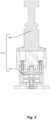
- Fig. 1 is a vertical section of the pulsatile fluid pump system 301 showing the controller system 311 (with electrical output 311b), power amplifier 321 (with electrical input 321a and electrical output 321b), linear motor 330 (comprised of a stationary member 331 which includes a coil 332 [with electrical input 332a], a frame 333, and cooling fins 334, and a moving member which includes a spring 338 of Fig. 4 and a magnet 339), position sensor 371, push rod assembly 341 (comprised of a push rod 342 and force sensor 372), flexible seal 351, control housing 361, and chassis 363.
- controller system 311 with electrical output 311b
- power amplifier 321 with electrical input 321a and electrical output 321b
- linear motor 330 (comprised of a stationary member 331 which includes a coil 332 [with electrical input 332a], a frame 333, and cooling fins 334, and a moving member which includes a spring 338 of Fig. 4 and a magnet 3
- An integral pump assembly 200 (comprised of the pump-valving assembly 101 with chamber 102, diaphragm assembly 201, and peripheral flange 221a ) is held by the peripheral flange 221a and compliant member (not shown) in the channel 362 within the control housing 361. (In these figures, like numbered items correspond to similar components across different figures.)
- Fig. 2 is an example of a touch-sensitive graphic display 400 user interface showing user-specifiable motor parameters 401.
- parameters stroke strength 401a and beat rate 401b are a subset of user-specifiable parameters defining the performance of the linear motor.
- flow characteristics 411 average flow rate 411a , stroke volume 411b, flow index 411c
- flow rate waveform 412 stroke volume waveform 413
- timer 414 timer 414.
- These flow-based attributes are a subset of physical flow characteristics.
- the user interface displays user-specifiable inputs 421 (low flow limit 421a , high flow limit 421b, and body surface area 421c).
- Fig. 3 is a vertical section of the push rod assembly 341 comprised of a push rod 342 and force sensor 372.
- Fig. 4 is a vertical section of the linear motor 330, showing the coil 332 with electrical input 332a , the frame 333, the magnet centering spring 338, and the magnet 339. Other components and detail of the motor are provided in Fig. 1 .
- the waveform program 511 is a computer program executed by the controller system 311 microprocessor 311c which accepts input from a set of sensors 370 (including position sensor 371 of Fig. 1 , force sensor 372 of Figs. 1 and 3 , and an external flow sensor 373 of Fig. 8 ), a set of user-specifiable motor parameters 401 (stroke strength 401a and beat rate 401b) defining performance of a linear motor 330 in the course of pumping. Additionally, Fig. 5 shows a set of user-specifiable input parameters 421 (low flow limit 421a , high flow limit 421b, and body surface area 421c). The waveform program 511 outputs an electrical waveform 512, the result of a set of algorithms 513, at the electrical output 311b. The electrical output 311b is coupled to electrical input 332a of linear motor 330.
- pulsatile pump should include both sufficient hemodynamic energy and a human-like waveform architecture.
- the human heart delivers a proper stroke volume at a natural cadence with a physiologic rest at the end of each stroke, adapting to the physiologic demands of the patient by adjusting the cardiac output, as the product of stroke volume and beat rate. Via the left ventricle, the human heart provides hemodynamic energy that results in a pressure wave that propagates fully through the elastic arterial tree.
- the waveform program 511 causes the pulsatile fluid pump system 301 to replicate the ability of the left ventricle of the human heart to deliver physiological hemodynamic energy proportional to a user-specified stroke strength 401a by causing delivery of the necessary fraction of the stroke volume of a pump chamber 102 in a physiologic natural cadence at a user-specified beat rate 401b. It is a user (a perfusionist) of the pulsatile fluid pump system 301 who adjusts the stroke strength 401a (an indirect specification of stroke volume) and beat rate 401b to meet the physiologic demand of the patient. Furthermore, the waveform program 511 replicates the physiologic rest at the end of each stroke, thereby allowing natural relaxation of the arterial tree.
- the structure of a pulsatile pump in accordance with various embodiments of the present invention can usefully reflect attributes of the human heart.
- the human heart is preload sensitive-the heart cannot "pull" blood into the left ventricle; it can only allow the blood available to flow naturally into the ventricle.
- the human heart is also afterload sensitive in that it is responsive to the compliance and resistance in the downstream vasculature and doesn't exert excess force on the blood, which could damage the vasculature.
- the left ventricle cannot deliver blood that isn't in the ventricle when it contracts; there is a limited bolus of blood that it can deliver.
- the pulsatile fluid pump system 301 has similar attributes of inherent safety: it is preload and afterload sensitive, and it is limited in both the volume of blood it can deliver and the force at which it can deliver that bolus of blood.
- the pulsatile fluid pump system 301 allows gravity filling from the venous reservoir, exerting minimal negative pressure.
- the linear motor 330 is inherently limited in the force that it can generate by its design. As such, it cannot overpressure the downstream tubing or vasculature, instead delivering less than the volume of blood in the pump chamber 102, thereby only delivering as much volume as the vasculature can receive.
- the integral pump assembly 200 is analogous to a left ventricle of the human heart; the inlet ball check valve assembly used in various embodiments hereof is analogous to a mitral valve; and the outlet ball check valve assembly used in various embodiments hereof is analogous to an aortic valve.
- the inlet and outlet ball check valve assemblies are passive and require a slight reversal of flow to close. This slight reversal of flow mimics the slight reversal that occurs when the aortic valve of the human heart closes.
- the waveform program 511a is a computer program executed by the controller system 311 microprocessor 311c which accepts input from a set of sensors 370, a set of user-specifiable motor parameters 401, and a set of user-specifiable input parameters 421.
- the waveform program 511a is configured to simulate a waveform that has been experimentally determined to be appropriate for embodiments of the pulsatile fluid pump system 301 of the present invention.
- the waveform program 511a simulates the experimentally determined waveform by repeatedly performing a multi-piece polynomial spline algorithm 513a and the resulting waveform is used to drive the linear motor 330.
- the waveform program 511a uses zero or more of the current and/or previous values from the set of sensors 370, along with the set of user-specifiable motor parameters 401, zero or more flow characteristics 411, zero or more user-specifiable input parameters 421, and the current electrical waveform 512a to create a new electrical waveform 512b.
- the waveform program 511a outputs the new electrical waveform 512b, consisting of discrete output voltages at defined time durations, at the electrical output 311b.
- the electrical output 311b is coupled to electrical input 332a of linear motor 330.
- the waveform program 511b is a computer program executed by the controller system 311 microprocessor 311c which accepts input from a set of sensors 370, a set of user-specifiable motor parameters 401, and a set of user-specifiable input parameters 421.
- the waveform program 511b reads an archetype electrical waveform 512c stored electronically within the controller system 311.
- the waveform program 511b then uses an algorithm 513b to adjust the archetype electrical waveform 512c .
- the algorithm 513b creates a new electrical waveform 512b from the archetype electrical waveform 512c using zero or more of the current and/or previous values of the set of sensors 370, along with the set of user-specifiable motor parameters 401, zero or more flow characteristics 411, zero or more user-specifiable input parameters 421, and the current electrical waveform 512a.
- the waveform program 511b outputs the new electrical waveform 512b, consisting of discrete output voltages at defined time durations, at the electrical output 311b.
- the electrical output 311b is coupled to electrical input 332a of linear motor 330.
- the graphics program 611 is a computer program executed by the controller system 311, which accepts user-specifiable motor parameters 401 and user-specifiable input parameters 421.
- the graphics program 611 causes a set of current values of the user-specifiable motor parameters 401, a set of flow characteristics 411, and a set of user-specifiable input parameters 421 to be shown on the graphic display 400.
- the graphics program 611 sets timer 414 to zero, increments the timer 414 in real time, and causes, each second, the updated timer 414 value to be shown on the graphic display 400.
- the graphics program 611 stops incrementing the timer 414 and causes the most recent value of timer 414 to be shown on the graphic display 400.
- the graphics program 611 accepts input from the flow sensor 373, calculates the average flow rate 411a, and causes the average flow rate 411a to be shown on the graphic display 400.
- the graphics program 611 also causes, in near real-time, the instantaneous flow rate as a flow rate waveform 412 to be shown on the graphic display 400.
- the graphics program 611 also uses data from the flow sensor 373 to calculate the average stroke volume 411b and cause the average stroke volume 411b to be shown on the graphic display 400.
- the graphics program 611 also causes, in near real-time, the total volume of fluid currently delivered for a given stroke to be shown on the graphic display 400.
- the total volume of fluid currently delivered for a given stroke is the integral of instantaneous flow as a stroke volume waveform 413 and is displayed as the shaded area under the flow rate waveform 412.
- the graphics program 611 accepts input of body surface area 421c and calculates flow index 411c as the average flow rate 411a divided by the body surface area 421c.
- the graphics program 611 further causes the body surface area 421c and calculated flow index 411c to be shown on the graphic display 400.
- the graphics program 611 accepts input of low flow limit 421a and high flow limit 421b, and causes the low flow limit 421a and high flow limit 421b settings to be shown on the graphic display 400.
Landscapes
- Health & Medical Sciences (AREA)
- Engineering & Computer Science (AREA)
- Heart & Thoracic Surgery (AREA)
- Mechanical Engineering (AREA)
- Cardiology (AREA)
- Hematology (AREA)
- Public Health (AREA)
- Biomedical Technology (AREA)
- Veterinary Medicine (AREA)
- Life Sciences & Earth Sciences (AREA)
- Animal Behavior & Ethology (AREA)
- General Health & Medical Sciences (AREA)
- Anesthesiology (AREA)
- General Engineering & Computer Science (AREA)
- Human Computer Interaction (AREA)
- Medical Informatics (AREA)
- External Artificial Organs (AREA)
- Reciprocating Pumps (AREA)
- Lubrication Of Internal Combustion Engines (AREA)
Description
- The present application is one of four applications being filed on the same day and bearing attorney docket numbers 4747/1001, 4747/1002, 4747/1003, and 4747/1004.
- The present invention relates to pulsatile fluid pumps, and more particularly to pulsatile fluid pumps suitable for pumping blood.
- A pulsatile fluid pump is taught in
U.S. patent 7,850,593 ("our prior patent") for an invention of Douglas Vincent and Matthew Murphy, who are co-inventors of the present invention. Our prior patent discloses a pump actuated by a linear motor configured to cause reciprocation of a flexible membrane, serving as a wall of a fluid housing, that is in turn coupled to a pair of ball valves, in a manner as to implement pulsatile fluid flow. Further relevant prior art is for instance disclosed in documentsUS2020/289731 A1 ,US2012/245405 A1 andUS2015/078934 A1 . - A pulsatile fluid pump system according to the present invention comprises the technical features of independent claim 1.
- The pulsatile fluid pump system for driving a fluid pump assembly includes a reciprocating linear motor having a magnet and a coil, the magnet moving in relation to the coil, the coil having an electrical input. The pulsatile fluid pump system further includes a controller system having an electrical output coupled to the electrical input of the coil, and the controller system is configured to execute a waveform program defining an electrical waveform at the electrical output. The waveform program is configured to control operation of the linear motor by modification of a feature, selected from the group consisting of amplitude, frequency, shape, and combinations thereof, of the electrical waveform at the electrical output. The waveform program is further configured to accept a set of user-specifiable parameters defining the performance of the linear motor and to modify the electrical waveform in response to such parameters.
- Optionally, the pulsatile fluid pump system further includes a graphic display, coupled to the controller system, the controller system executing a graphics program configured to cause the graphic display to show a set of user-specifiable parameters defining the performance of the linear motor.
- Optionally, the pulsatile fluid pump system further includes a flow sensor mechanically coupled to a fluid path including the integrated pump assembly, the flow sensor having an electrical output coupled to the controller system, wherein the controller system is executing a graphics program configured to cause the graphic display to show a set of items, including values of a set of user-specifiable parameters defining the performance of the linear motor and values of a set of physical flow characteristics.
- Optionally, the set of items shown includes an instantaneous flow rate waveform in near real-time. Optionally, set of items shown includes an instantaneous stroke volume waveform in near real-time.
- Optionally, the waveform program is configured to generate the electrical waveform at the electrical output by repeatedly performing a multi-piece polynomial spline algorithm in a manner responsive to a set of user-specifiable parameters defining the performance of the linear motor.
- According to the invention as claimed, the controller system has a storage system in which is stored an archetype electrical waveform, and the waveform program reads the archetype electrical waveform from the storage system and modifies the archetype electrical waveform, based upon a set of user-specifiable parameters defining the performance of the linear motor, to generate the electrical waveform at the electrical output.
- Optionally, the pulsatile fluid pump system further includes a set of sensors, electrically coupled to the controller system and configured to produce a set of sensor outputs corresponding to pumping performance. The waveform program is configured to generate the electrical waveform at the electrical output in a manner responsive to the set of sensor outputs and a set of user-specifiable parameters.
- Also optionally, the user of the pulsatile fluid pump system may choose from a set of waveform programs. Optionally, the graphic display is touch sensitive.
- The foregoing features of embodiments will be more readily understood by reference to the following detailed description, taken with reference to the accompanying drawings, in which:
-
Fig. 1 is a vertical section of the pulsatilefluid pump system 301 showing thecontroller system 311,power amplifier 321, linear motor 330 (coil 332,cooling fins 334, and magnet 339),push rod assembly 341,flexible seal 351,control housing 361, and theintegral pump assembly 200. -
Fig. 2 is an example of the touch-sensitivegraphic display 400 user interface showing the user-specifiable motor parameters 401,flow characteristics 411, and user-specifiable input parameters 421. -
Fig. 3 is a vertical section of thepush rod assembly 341. -
Fig. 4 is a vertical section of thelinear motor 330. -
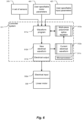
Fig. 5 is a block diagram describing a waveform program -
Fig. 6 is a block diagram describing afirst embodiment 511a of thewaveform program 511. -
Fig. 7 is a block diagram describing asecond embodiment 511b of thewaveform program 511. -
Fig. 8 is a block diagram describing agraphics program 611. - Definitions. As used in this description and the accompanying claims, the following terms shall have the meanings indicated, unless the context otherwise requires:
A "set" includes at least one member. - An "electrical waveform" is a waveform selected from the group consisting of an electrical current waveform, a voltage waveform, and combinations thereof.
- The term "user-specifiable input parameter" includes a user-definable attribute pertinent to an alarm setting or calculation for a user interface, such as
low flow limit 421a,high flow limit 421b, andbody surface area 421c (BSA), as well as combinations of any of the foregoing attributes. - The term "user-specifiable parameter defining the performance of the linear motor" in the course of pumping includes a motor performance attribute such as stroke strength 401a,
beat rate 401b, flow rate, average flow rate, stroke volume, flow index, pulse pressure, output pressure, magnet displacement, as well as combinations of any of the foregoing attributes. - The term "physical flow characteristic" includes a measured attribute such as stroke strength, beat rate, flow rate,
average flow rate 411a,stroke volume 411b,flow index 411c, pulse pressure,flow rate waveform 412,stroke volume waveform 413, duration over which the pump has been running (e.g., measured by timer 414), as well as combinations of any of the foregoing attributes. If an attribute is user-specified in a given embodiment of the present invention, then measurement of the attribute is of subsidiary importance since its value has been specified. Similarly, if an attribute being measured has primary importance in a given embodiment of the present invention, then the parameter would not have been user-specified. -
Fig. 1 is a vertical section of the pulsatilefluid pump system 301 showing the controller system 311 (withelectrical output 311b), power amplifier 321 (with electrical input 321a and electrical output 321b), linear motor 330 (comprised of astationary member 331 which includes a coil 332 [withelectrical input 332a], aframe 333, andcooling fins 334, and a moving member which includes aspring 338 ofFig. 4 and a magnet 339),position sensor 371, push rod assembly 341 (comprised of apush rod 342 and force sensor 372),flexible seal 351,control housing 361, andchassis 363. An integral pump assembly 200 (comprised of the pump-valving assembly 101 withchamber 102,diaphragm assembly 201, andperipheral flange 221a) is held by theperipheral flange 221a and compliant member (not shown) in thechannel 362 within thecontrol housing 361. (In these figures, like numbered items correspond to similar components across different figures.) -
Fig. 2 is an example of a touch-sensitivegraphic display 400 user interface showing user-specifiable motor parameters 401. In this interface appear parameters stroke strength 401a andbeat rate 401b. These parameters are a subset of user-specifiable parameters defining the performance of the linear motor. Additionally, in this interface appear flow characteristics 411 (average flow rate 411a,stroke volume 411b,flow index 411c),flow rate waveform 412,stroke volume waveform 413, andtimer 414. These flow-based attributes are a subset of physical flow characteristics. Additionally, the user interface displays user-specifiable inputs 421 (low flow limit 421a,high flow limit 421b, andbody surface area 421c). -
Fig. 3 is a vertical section of thepush rod assembly 341 comprised of apush rod 342 andforce sensor 372. -
Fig. 4 is a vertical section of thelinear motor 330, showing thecoil 332 withelectrical input 332a, theframe 333, themagnet centering spring 338, and themagnet 339. Other components and detail of the motor are provided inFig. 1 . - In
Fig. 5 , thewaveform program 511 is a computer program executed by thecontroller system 311microprocessor 311c which accepts input from a set of sensors 370 (includingposition sensor 371 ofFig. 1 ,force sensor 372 ofFigs. 1 and3 , and anexternal flow sensor 373 ofFig. 8 ), a set of user-specifiable motor parameters 401 (stroke strength 401a andbeat rate 401b) defining performance of alinear motor 330 in the course of pumping. Additionally,Fig. 5 shows a set of user-specifiable input parameters 421 (low flow limit 421a,high flow limit 421b, andbody surface area 421c). Thewaveform program 511 outputs anelectrical waveform 512, the result of a set ofalgorithms 513, at theelectrical output 311b. Theelectrical output 311b is coupled toelectrical input 332a oflinear motor 330. - There is growing consensus that desirable characteristics of a pulsatile pump should include both sufficient hemodynamic energy and a human-like waveform architecture. To evaluate pulsatile flow, we choose the human heart as the best model: it delivers a proper stroke volume at a natural cadence with a physiologic rest at the end of each stroke, adapting to the physiologic demands of the patient by adjusting the cardiac output, as the product of stroke volume and beat rate. Via the left ventricle, the human heart provides hemodynamic energy that results in a pressure wave that propagates fully through the elastic arterial tree. It appears that only a biomimetic stroke volume delivered in a biomimetic time frame (like the native systolic contraction produced by the heart) allows the elastic arterial tree to properly relax during the diastolic phase. Use of continuous flow devices stretches the elastic arterial wall but never allows proper relaxation, creating constant and atypical stress on the endothelial cells and interfering with natural baroreceptor sympathetic and parasympathetic signaling, thus disrupting the body's homeostatic control state.
- The
waveform program 511 causes the pulsatilefluid pump system 301 to replicate the ability of the left ventricle of the human heart to deliver physiological hemodynamic energy proportional to a user-specified stroke strength 401a by causing delivery of the necessary fraction of the stroke volume of apump chamber 102 in a physiologic natural cadence at a user-specifiedbeat rate 401b. It is a user (a perfusionist) of the pulsatilefluid pump system 301 who adjusts the stroke strength 401a (an indirect specification of stroke volume) and beatrate 401b to meet the physiologic demand of the patient. Furthermore, thewaveform program 511 replicates the physiologic rest at the end of each stroke, thereby allowing natural relaxation of the arterial tree. - The structure of a pulsatile pump in accordance with various embodiments of the present invention can usefully reflect attributes of the human heart. The human heart is preload sensitive-the heart cannot "pull" blood into the left ventricle; it can only allow the blood available to flow naturally into the ventricle. The human heart is also afterload sensitive in that it is responsive to the compliance and resistance in the downstream vasculature and doesn't exert excess force on the blood, which could damage the vasculature. Lastly, the left ventricle cannot deliver blood that isn't in the ventricle when it contracts; there is a limited bolus of blood that it can deliver.
- The pulsatile
fluid pump system 301 has similar attributes of inherent safety: it is preload and afterload sensitive, and it is limited in both the volume of blood it can deliver and the force at which it can deliver that bolus of blood. When filling, the pulsatilefluid pump system 301 allows gravity filling from the venous reservoir, exerting minimal negative pressure. When emptying, thelinear motor 330 is inherently limited in the force that it can generate by its design. As such, it cannot overpressure the downstream tubing or vasculature, instead delivering less than the volume of blood in thepump chamber 102, thereby only delivering as much volume as the vasculature can receive. - The
integral pump assembly 200 is analogous to a left ventricle of the human heart; the inlet ball check valve assembly used in various embodiments hereof is analogous to a mitral valve; and the outlet ball check valve assembly used in various embodiments hereof is analogous to an aortic valve. Like the human heart, the inlet and outlet ball check valve assemblies are passive and require a slight reversal of flow to close. This slight reversal of flow mimics the slight reversal that occurs when the aortic valve of the human heart closes. - In one embodiment of the present invention, shown in
Fig. 6 , thewaveform program 511a is a computer program executed by thecontroller system 311microprocessor 311c which accepts input from a set ofsensors 370, a set of user-specifiable motor parameters 401, and a set of user-specifiable input parameters 421. Thewaveform program 511a is configured to simulate a waveform that has been experimentally determined to be appropriate for embodiments of the pulsatilefluid pump system 301 of the present invention. Thewaveform program 511a simulates the experimentally determined waveform by repeatedly performing a multi-piecepolynomial spline algorithm 513a and the resulting waveform is used to drive thelinear motor 330. In the event that the user changes one of the user-specifiable motor parameters 401, thewaveform program 511a uses zero or more of the current and/or previous values from the set ofsensors 370, along with the set of user-specifiable motor parameters 401, zero ormore flow characteristics 411, zero or more user-specifiable input parameters 421, and the currentelectrical waveform 512a to create a newelectrical waveform 512b. Thewaveform program 511a outputs the newelectrical waveform 512b, consisting of discrete output voltages at defined time durations, at theelectrical output 311b. Theelectrical output 311b is coupled toelectrical input 332a oflinear motor 330. - In another embodiment of the present invention, shown in
Fig. 7 , thewaveform program 511b is a computer program executed by thecontroller system 311microprocessor 311c which accepts input from a set ofsensors 370, a set of user-specifiable motor parameters 401, and a set of user-specifiable input parameters 421. Thewaveform program 511b reads an archetypeelectrical waveform 512c stored electronically within thecontroller system 311. Thewaveform program 511b then uses analgorithm 513b to adjust the archetypeelectrical waveform 512c. Thealgorithm 513b creates a newelectrical waveform 512b from the archetypeelectrical waveform 512c using zero or more of the current and/or previous values of the set ofsensors 370, along with the set of user-specifiable motor parameters 401, zero ormore flow characteristics 411, zero or more user-specifiable input parameters 421, and the currentelectrical waveform 512a. Thewaveform program 511b outputs the newelectrical waveform 512b, consisting of discrete output voltages at defined time durations, at theelectrical output 311b. Theelectrical output 311b is coupled toelectrical input 332a oflinear motor 330. - In
Fig. 8 , thegraphics program 611 is a computer program executed by thecontroller system 311, which accepts user-specifiable motor parameters 401 and user-specifiable input parameters 421. Thegraphics program 611 causes a set of current values of the user-specifiable motor parameters 401, a set offlow characteristics 411, and a set of user-specifiable input parameters 421 to be shown on thegraphic display 400. - When the stroke strength 401a value transitions from zero to a positive value, the
graphics program 611 setstimer 414 to zero, increments thetimer 414 in real time, and causes, each second, the updatedtimer 414 value to be shown on thegraphic display 400. When the stroke strength 401a value transitions from a positive value to zero, thegraphics program 611 stops incrementing thetimer 414 and causes the most recent value oftimer 414 to be shown on thegraphic display 400. - The
graphics program 611 accepts input from theflow sensor 373, calculates theaverage flow rate 411a, and causes theaverage flow rate 411a to be shown on thegraphic display 400. Thegraphics program 611 also causes, in near real-time, the instantaneous flow rate as aflow rate waveform 412 to be shown on thegraphic display 400. - The
graphics program 611 also uses data from theflow sensor 373 to calculate theaverage stroke volume 411b and cause theaverage stroke volume 411b to be shown on thegraphic display 400. Thegraphics program 611 also causes, in near real-time, the total volume of fluid currently delivered for a given stroke to be shown on thegraphic display 400. The total volume of fluid currently delivered for a given stroke is the integral of instantaneous flow as astroke volume waveform 413 and is displayed as the shaded area under theflow rate waveform 412. - The
graphics program 611 accepts input ofbody surface area 421c and calculatesflow index 411c as theaverage flow rate 411a divided by thebody surface area 421c. Thegraphics program 611 further causes thebody surface area 421c and calculatedflow index 411c to be shown on thegraphic display 400. - The
graphics program 611 accepts input oflow flow limit 421a andhigh flow limit 421b, and causes thelow flow limit 421a andhigh flow limit 421b settings to be shown on thegraphic display 400. - The embodiments of the invention described above are intended to be merely exemplary. The scope of the present invention is defined by the appended claims.
Claims (9)
- A pulsatile fluid pump system for driving a fluid pump assembly, the pulsatile fluid pump system comprising:a reciprocating linear motor (330) having a magnet (339) and a coil (332), the magnet moving in relation to the coil, the coil having an electrical input (332a);a controller system (311) having an electrical output (311b) coupled to the electrical input of the coil and a storage system in which is stored an archetype waveform (512c), the controller system being configured to execute a waveform program (511b) defining an electrical waveform (512b) at the electrical output;wherein the waveform program is configured to accept user-provided values of a set of user-specifiable parameters defining performance of the linear motor and further configured to read the archetype electrical waveform from the storage system and to generate the electrical waveform at the electrical output by modifying the archetype electrical waveform with respect to a feature, selected from the group consisting of amplitude, frequency, shape, and combinations thereof, in response to the user-provided values for such parameters.
- A pulsatile fluid pump system according to claim 1, further comprising a graphic display (400), coupled to the controller system (311), the controller system executing a graphics program (611) configured to cause the graphic display to show a set of user-specifiable parameters defining the performance of the linear motor.
- A pulsatile fluid pump system according to claim 2, further comprising a flow sensor (373) mechanically coupled to a fluid path including the integrated pump assembly, the flow sensor having an electrical output coupled to the controller system, wherein the controller system is executing a graphics program (611) configured to cause the graphic display (400) to show a set of items, including values of a set of user-specifiable parameters defining the performance of the linear motor and values of a set of physical flow characteristics.
- A pulsatile fluid pump system according to claim 3, wherein the set of items shown includes an instantaneous flow rate waveform in near real-time.
- A pulsatile fluid pump system according to claim 3, wherein the set of items shown includes an instantaneous stroke volume waveform in near real-time.
- A pulsatile fluid pump system according to claim 1, wherein the waveform program (511b) is configured to generate the electrical waveform (512b) at the electrical output (311b) by repeatedly performing a multi-piece polynomial spline algorithm in a manner responsive to a set of user-specifiable parameters defining the performance of the linear motor (330).
- A pulsatile fluid pump system according to claim 1, further comprising a set of sensors (370), electrically coupled to the controller system (311) and configured to produce a set of sensor outputs corresponding to pumping performance, wherein the waveform program (511b) is configured to generate the electrical waveform (512b) at the electrical output in a manner responsive to the set of sensor outputs and a set of user-specifiable parameters.
- A pulsatile fluid pump system according to claim 1, wherein the user of the pulsatile fluid pump system may choose from a set of waveform programs.
- A pulsatile fluid pump system according to claim 2, wherein the graphic display (400) is touch sensitive.
Applications Claiming Priority (1)
| Application Number | Priority Date | Filing Date | Title |
|---|---|---|---|
| PCT/US2021/019262 WO2022182334A1 (en) | 2021-02-23 | 2021-02-23 | System for driving a pulsatile fluid pump |
Publications (2)
| Publication Number | Publication Date |
|---|---|
| EP4297842A1 EP4297842A1 (en) | 2024-01-03 |
| EP4297842B1 true EP4297842B1 (en) | 2025-02-12 |
Family
ID=74875361
Family Applications (1)
| Application Number | Title | Priority Date | Filing Date |
|---|---|---|---|
| EP21712365.2A Active EP4297842B1 (en) | 2021-02-23 | 2021-02-23 | System for driving a pulsatile fluid pump |
Country Status (4)
| Country | Link |
|---|---|
| EP (1) | EP4297842B1 (en) |
| JP (1) | JP7608638B2 (en) |
| AU (1) | AU2021429723A1 (en) |
| WO (1) | WO2022182334A1 (en) |
Family Cites Families (6)
| Publication number | Priority date | Publication date | Assignee | Title |
|---|---|---|---|---|
| DK2298370T3 (en) | 2002-02-21 | 2014-01-27 | Design Mentor Inc | fluid pump |
| US8540617B2 (en) * | 2007-04-20 | 2013-09-24 | Medical Engineering Company, Llc | Extracorporeal pumping methods |
| JP5587958B2 (en) * | 2012-10-19 | 2014-09-10 | 日機装株式会社 | Ironing type pump |
| WO2015042098A1 (en) * | 2013-09-18 | 2015-03-26 | Aavid Thermalloy, Llc | Split fluidic diaphragm |
| US9968720B2 (en) * | 2016-04-11 | 2018-05-15 | CorWave SA | Implantable pump system having an undulating membrane |
| US10799625B2 (en) * | 2019-03-15 | 2020-10-13 | CorWave SA | Systems and methods for controlling an implantable blood pump |
-
2021
- 2021-02-23 AU AU2021429723A patent/AU2021429723A1/en active Pending
- 2021-02-23 EP EP21712365.2A patent/EP4297842B1/en active Active
- 2021-02-23 JP JP2023575495A patent/JP7608638B2/en active Active
- 2021-02-23 WO PCT/US2021/019262 patent/WO2022182334A1/en not_active Ceased
Also Published As
| Publication number | Publication date |
|---|---|
| JP7608638B2 (en) | 2025-01-06 |
| EP4297842A1 (en) | 2024-01-03 |
| AU2021429723A1 (en) | 2023-09-21 |
| JP2024511903A (en) | 2024-03-15 |
| WO2022182334A1 (en) | 2022-09-01 |
Similar Documents
| Publication | Publication Date | Title |
|---|---|---|
| US6623420B2 (en) | Physiological heart pump control | |
| US10799625B2 (en) | Systems and methods for controlling an implantable blood pump | |
| US8943429B2 (en) | State machine user and validation interface system | |
| CN111084674B (en) | In vitro simulated circulatory system for artificial heart testing | |
| Baloa et al. | Elastance-based control of a mock circulatory system | |
| CN108682255B (en) | Pulsating heart model and pulsation control method thereof | |
| Gregory et al. | Replication of the Frank-Starling response in a mock circulation loop | |
| US20040097782A1 (en) | Optimized pulsatile-flow ventricular-assist device and total artificial heart | |
| Bullister et al. | Physiologic control algorithms for rotary blood pumps using pressure sensor input | |
| Zannoli et al. | Mechanical simulator of the cardiovascular system | |
| EP2050030A1 (en) | State space model of a heart | |
| Colacino et al. | A modified elastance model to control mock ventricles in real-time: numerical and experimental validation | |
| CN118887853A (en) | A right ventricular assist device body-lung dual circulation simulation system | |
| US11300119B1 (en) | System for driving a pulsatile fluid pump | |
| Jaron et al. | Theoretical Considerations Regarding the Optimization of Cardiac Assistance by lntraaortic Balloon Pumping | |
| Simaan | Rotary heart assist devices | |
| EP4297842A1 (en) | System for driving a pulsatile fluid pump | |
| US20240426288A1 (en) | Pulsatile Fluid Pump System | |
| US7239987B2 (en) | Computer based system adapted to create a representation of the pumping action of a heart | |
| WO2022182335A1 (en) | Pulsatile fluid pump system | |
| Noordergraaf et al. | The donders model of the circulation in normo-and pathophysiology | |
| Yoshizawa et al. | An automatic control algorithm for the optimal driving of the ventricular-assist device | |
| CN117831378A (en) | A pulse wave simulation teaching device | |
| CN209137530U (en) | Using the heart analog machine of pneumatic shuttle | |
| Anderson et al. | Analog simulation of left ventricular bypass mode control |
Legal Events
| Date | Code | Title | Description |
|---|---|---|---|
| STAA | Information on the status of an ep patent application or granted ep patent |
Free format text: STATUS: UNKNOWN |
|
| STAA | Information on the status of an ep patent application or granted ep patent |
Free format text: STATUS: THE INTERNATIONAL PUBLICATION HAS BEEN MADE |
|
| PUAI | Public reference made under article 153(3) epc to a published international application that has entered the european phase |
Free format text: ORIGINAL CODE: 0009012 |
|
| STAA | Information on the status of an ep patent application or granted ep patent |
Free format text: STATUS: REQUEST FOR EXAMINATION WAS MADE |
|
| 17P | Request for examination filed |
Effective date: 20230905 |
|
| AK | Designated contracting states |
Kind code of ref document: A1 Designated state(s): AL AT BE BG CH CY CZ DE DK EE ES FI FR GB GR HR HU IE IS IT LI LT LU LV MC MK MT NL NO PL PT RO RS SE SI SK SM TR |
|
| DAV | Request for validation of the european patent (deleted) | ||
| DAX | Request for extension of the european patent (deleted) | ||
| GRAP | Despatch of communication of intention to grant a patent |
Free format text: ORIGINAL CODE: EPIDOSNIGR1 |
|
| STAA | Information on the status of an ep patent application or granted ep patent |
Free format text: STATUS: GRANT OF PATENT IS INTENDED |
|
| INTG | Intention to grant announced |
Effective date: 20240904 |
|
| GRAS | Grant fee paid |
Free format text: ORIGINAL CODE: EPIDOSNIGR3 |
|
| GRAA | (expected) grant |
Free format text: ORIGINAL CODE: 0009210 |
|
| STAA | Information on the status of an ep patent application or granted ep patent |
Free format text: STATUS: THE PATENT HAS BEEN GRANTED |
|
| AK | Designated contracting states |
Kind code of ref document: B1 Designated state(s): AL AT BE BG CH CY CZ DE DK EE ES FI FR GB GR HR HU IE IS IT LI LT LU LV MC MK MT NL NO PL PT RO RS SE SI SK SM TR |
|
| REG | Reference to a national code |
Ref country code: GB Ref legal event code: FG4D |
|
| RIN1 | Information on inventor provided before grant (corrected) |
Inventor name: SHIELDS, PATRICK Inventor name: MURPHY, MATTHEW J. Inventor name: VINCENT, KATHLEEN Inventor name: LABONTE, JUDY Inventor name: NABER, JEFFREY P. Inventor name: SMITH, ERIC Inventor name: OLNEY, DAVID Inventor name: BZURA, CONRAD Inventor name: BAILEY, BRIAN Inventor name: VINCENT, DOUGLAS E. |
|
| REG | Reference to a national code |
Ref country code: CH Ref legal event code: EP |
|
| P01 | Opt-out of the competence of the unified patent court (upc) registered |
Free format text: CASE NUMBER: APP_3991/2025 Effective date: 20250124 |
|
| REG | Reference to a national code |
Ref country code: DE Ref legal event code: R096 Ref document number: 602021025984 Country of ref document: DE |
|
| REG | Reference to a national code |
Ref country code: IE Ref legal event code: FG4D |
|
| PGFP | Annual fee paid to national office [announced via postgrant information from national office to epo] |
Ref country code: DE Payment date: 20250327 Year of fee payment: 5 |
|
| PGFP | Annual fee paid to national office [announced via postgrant information from national office to epo] |
Ref country code: AT Payment date: 20250417 Year of fee payment: 5 |
|
| PGFP | Annual fee paid to national office [announced via postgrant information from national office to epo] |
Ref country code: FR Payment date: 20250325 Year of fee payment: 5 |
|
| PGFP | Annual fee paid to national office [announced via postgrant information from national office to epo] |
Ref country code: GB Payment date: 20250327 Year of fee payment: 5 |
|
| REG | Reference to a national code |
Ref country code: NL Ref legal event code: MP Effective date: 20250212 |
|
| PG25 | Lapsed in a contracting state [announced via postgrant information from national office to epo] |
Ref country code: RS Free format text: LAPSE BECAUSE OF FAILURE TO SUBMIT A TRANSLATION OF THE DESCRIPTION OR TO PAY THE FEE WITHIN THE PRESCRIBED TIME-LIMIT Effective date: 20250512 |
|
| PG25 | Lapsed in a contracting state [announced via postgrant information from national office to epo] |
Ref country code: FI Free format text: LAPSE BECAUSE OF FAILURE TO SUBMIT A TRANSLATION OF THE DESCRIPTION OR TO PAY THE FEE WITHIN THE PRESCRIBED TIME-LIMIT Effective date: 20250212 |
|
| PG25 | Lapsed in a contracting state [announced via postgrant information from national office to epo] |
Ref country code: PL Free format text: LAPSE BECAUSE OF FAILURE TO SUBMIT A TRANSLATION OF THE DESCRIPTION OR TO PAY THE FEE WITHIN THE PRESCRIBED TIME-LIMIT Effective date: 20250212 |
|
| PG25 | Lapsed in a contracting state [announced via postgrant information from national office to epo] |
Ref country code: ES Free format text: LAPSE BECAUSE OF FAILURE TO SUBMIT A TRANSLATION OF THE DESCRIPTION OR TO PAY THE FEE WITHIN THE PRESCRIBED TIME-LIMIT Effective date: 20250212 |
|
| REG | Reference to a national code |
Ref country code: LT Ref legal event code: MG9D |
|
| PG25 | Lapsed in a contracting state [announced via postgrant information from national office to epo] |
Ref country code: IS Free format text: LAPSE BECAUSE OF FAILURE TO SUBMIT A TRANSLATION OF THE DESCRIPTION OR TO PAY THE FEE WITHIN THE PRESCRIBED TIME-LIMIT Effective date: 20250612 Ref country code: NO Free format text: LAPSE BECAUSE OF FAILURE TO SUBMIT A TRANSLATION OF THE DESCRIPTION OR TO PAY THE FEE WITHIN THE PRESCRIBED TIME-LIMIT Effective date: 20250512 |
|
| PG25 | Lapsed in a contracting state [announced via postgrant information from national office to epo] |
Ref country code: NL Free format text: LAPSE BECAUSE OF FAILURE TO SUBMIT A TRANSLATION OF THE DESCRIPTION OR TO PAY THE FEE WITHIN THE PRESCRIBED TIME-LIMIT Effective date: 20250212 |
|
| PGFP | Annual fee paid to national office [announced via postgrant information from national office to epo] |
Ref country code: IT Payment date: 20250521 Year of fee payment: 5 |
|
| PG25 | Lapsed in a contracting state [announced via postgrant information from national office to epo] |
Ref country code: HR Free format text: LAPSE BECAUSE OF FAILURE TO SUBMIT A TRANSLATION OF THE DESCRIPTION OR TO PAY THE FEE WITHIN THE PRESCRIBED TIME-LIMIT Effective date: 20250212 |
|
| PG25 | Lapsed in a contracting state [announced via postgrant information from national office to epo] |
Ref country code: LV Free format text: LAPSE BECAUSE OF FAILURE TO SUBMIT A TRANSLATION OF THE DESCRIPTION OR TO PAY THE FEE WITHIN THE PRESCRIBED TIME-LIMIT Effective date: 20250212 Ref country code: PT Free format text: LAPSE BECAUSE OF FAILURE TO SUBMIT A TRANSLATION OF THE DESCRIPTION OR TO PAY THE FEE WITHIN THE PRESCRIBED TIME-LIMIT Effective date: 20250612 |
|
| PG25 | Lapsed in a contracting state [announced via postgrant information from national office to epo] |
Ref country code: GR Free format text: LAPSE BECAUSE OF FAILURE TO SUBMIT A TRANSLATION OF THE DESCRIPTION OR TO PAY THE FEE WITHIN THE PRESCRIBED TIME-LIMIT Effective date: 20250513 Ref country code: BG Free format text: LAPSE BECAUSE OF FAILURE TO SUBMIT A TRANSLATION OF THE DESCRIPTION OR TO PAY THE FEE WITHIN THE PRESCRIBED TIME-LIMIT Effective date: 20250212 |
|
| REG | Reference to a national code |
Ref country code: AT Ref legal event code: MK05 Ref document number: 1765518 Country of ref document: AT Kind code of ref document: T Effective date: 20250212 |
|
| PG25 | Lapsed in a contracting state [announced via postgrant information from national office to epo] |
Ref country code: SE Free format text: LAPSE BECAUSE OF FAILURE TO SUBMIT A TRANSLATION OF THE DESCRIPTION OR TO PAY THE FEE WITHIN THE PRESCRIBED TIME-LIMIT Effective date: 20250212 |
|
| REG | Reference to a national code |
Ref country code: CH Ref legal event code: PL |
|
| PG25 | Lapsed in a contracting state [announced via postgrant information from national office to epo] |
Ref country code: SM Free format text: LAPSE BECAUSE OF FAILURE TO SUBMIT A TRANSLATION OF THE DESCRIPTION OR TO PAY THE FEE WITHIN THE PRESCRIBED TIME-LIMIT Effective date: 20250212 |
|
| PG25 | Lapsed in a contracting state [announced via postgrant information from national office to epo] |
Ref country code: DK Free format text: LAPSE BECAUSE OF FAILURE TO SUBMIT A TRANSLATION OF THE DESCRIPTION OR TO PAY THE FEE WITHIN THE PRESCRIBED TIME-LIMIT Effective date: 20250212 |
|
| PG25 | Lapsed in a contracting state [announced via postgrant information from national office to epo] |
Ref country code: LU Free format text: LAPSE BECAUSE OF NON-PAYMENT OF DUE FEES Effective date: 20250223 |
|
| PG25 | Lapsed in a contracting state [announced via postgrant information from national office to epo] |
Ref country code: AT Free format text: LAPSE BECAUSE OF FAILURE TO SUBMIT A TRANSLATION OF THE DESCRIPTION OR TO PAY THE FEE WITHIN THE PRESCRIBED TIME-LIMIT Effective date: 20250212 |
|
| PG25 | Lapsed in a contracting state [announced via postgrant information from national office to epo] |
Ref country code: CH Free format text: LAPSE BECAUSE OF NON-PAYMENT OF DUE FEES Effective date: 20250228 |
|
| PG25 | Lapsed in a contracting state [announced via postgrant information from national office to epo] |
Ref country code: EE Free format text: LAPSE BECAUSE OF FAILURE TO SUBMIT A TRANSLATION OF THE DESCRIPTION OR TO PAY THE FEE WITHIN THE PRESCRIBED TIME-LIMIT Effective date: 20250212 Ref country code: CZ Free format text: LAPSE BECAUSE OF FAILURE TO SUBMIT A TRANSLATION OF THE DESCRIPTION OR TO PAY THE FEE WITHIN THE PRESCRIBED TIME-LIMIT Effective date: 20250212 |
|
| PG25 | Lapsed in a contracting state [announced via postgrant information from national office to epo] |
Ref country code: RO Free format text: LAPSE BECAUSE OF FAILURE TO SUBMIT A TRANSLATION OF THE DESCRIPTION OR TO PAY THE FEE WITHIN THE PRESCRIBED TIME-LIMIT Effective date: 20250212 |
|
| PG25 | Lapsed in a contracting state [announced via postgrant information from national office to epo] |
Ref country code: SK Free format text: LAPSE BECAUSE OF FAILURE TO SUBMIT A TRANSLATION OF THE DESCRIPTION OR TO PAY THE FEE WITHIN THE PRESCRIBED TIME-LIMIT Effective date: 20250212 |
|
| REG | Reference to a national code |
Ref country code: DE Ref legal event code: R097 Ref document number: 602021025984 Country of ref document: DE |
|
| REG | Reference to a national code |
Ref country code: BE Ref legal event code: MM Effective date: 20250228 |
|
| PLBE | No opposition filed within time limit |
Free format text: ORIGINAL CODE: 0009261 |
|
| STAA | Information on the status of an ep patent application or granted ep patent |
Free format text: STATUS: NO OPPOSITION FILED WITHIN TIME LIMIT |
|
| PG25 | Lapsed in a contracting state [announced via postgrant information from national office to epo] |
Ref country code: MC Free format text: LAPSE BECAUSE OF FAILURE TO SUBMIT A TRANSLATION OF THE DESCRIPTION OR TO PAY THE FEE WITHIN THE PRESCRIBED TIME-LIMIT Effective date: 20250212 |
|
| PG25 | Lapsed in a contracting state [announced via postgrant information from national office to epo] |
Ref country code: BE Free format text: LAPSE BECAUSE OF NON-PAYMENT OF DUE FEES Effective date: 20250228 |
|
| PG25 | Lapsed in a contracting state [announced via postgrant information from national office to epo] |
Ref country code: IE Free format text: LAPSE BECAUSE OF NON-PAYMENT OF DUE FEES Effective date: 20250223 |
|
| 26N | No opposition filed |
Effective date: 20251113 |