EP4297271A2 - System and method for attaching panels - Google Patents
System and method for attaching panels Download PDFInfo
- Publication number
- EP4297271A2 EP4297271A2 EP23208312.1A EP23208312A EP4297271A2 EP 4297271 A2 EP4297271 A2 EP 4297271A2 EP 23208312 A EP23208312 A EP 23208312A EP 4297271 A2 EP4297271 A2 EP 4297271A2
- Authority
- EP
- European Patent Office
- Prior art keywords
- suction cup
- panel
- ferromagnetic
- magnet
- state
- Prior art date
- Legal status (The legal status is an assumption and is not a legal conclusion. Google has not performed a legal analysis and makes no representation as to the accuracy of the status listed.)
- Withdrawn
Links
Images


Classifications
-
- H—ELECTRICITY
- H02—GENERATION; CONVERSION OR DISTRIBUTION OF ELECTRIC POWER
- H02S—GENERATION OF ELECTRIC POWER BY CONVERSION OF INFRARED RADIATION, VISIBLE LIGHT OR ULTRAVIOLET LIGHT, e.g. USING PHOTOVOLTAIC [PV] MODULES
- H02S30/00—Structural details of PV modules other than those related to light conversion
- H02S30/10—Frame structures
-
- E—FIXED CONSTRUCTIONS
- E04—BUILDING
- E04B—GENERAL BUILDING CONSTRUCTIONS; WALLS, e.g. PARTITIONS; ROOFS; FLOORS; CEILINGS; INSULATION OR OTHER PROTECTION OF BUILDINGS
- E04B1/00—Constructions in general; Structures which are not restricted either to walls, e.g. partitions, or floors or ceilings or roofs
- E04B1/38—Connections for building structures in general
- E04B1/388—Separate connecting elements
-
- H—ELECTRICITY
- H02—GENERATION; CONVERSION OR DISTRIBUTION OF ELECTRIC POWER
- H02S—GENERATION OF ELECTRIC POWER BY CONVERSION OF INFRARED RADIATION, VISIBLE LIGHT OR ULTRAVIOLET LIGHT, e.g. USING PHOTOVOLTAIC [PV] MODULES
- H02S20/00—Supporting structures for PV modules
- H02S20/20—Supporting structures directly fixed to an immovable object
-
- F—MECHANICAL ENGINEERING; LIGHTING; HEATING; WEAPONS; BLASTING
- F16—ENGINEERING ELEMENTS AND UNITS; GENERAL MEASURES FOR PRODUCING AND MAINTAINING EFFECTIVE FUNCTIONING OF MACHINES OR INSTALLATIONS; THERMAL INSULATION IN GENERAL
- F16B—DEVICES FOR FASTENING OR SECURING CONSTRUCTIONAL ELEMENTS OR MACHINE PARTS TOGETHER, e.g. NAILS, BOLTS, CIRCLIPS, CLAMPS, CLIPS OR WEDGES; JOINTS OR JOINTING
- F16B1/00—Devices for securing together, or preventing relative movement between, constructional elements or machine parts
-
- F—MECHANICAL ENGINEERING; LIGHTING; HEATING; WEAPONS; BLASTING
- F16—ENGINEERING ELEMENTS AND UNITS; GENERAL MEASURES FOR PRODUCING AND MAINTAINING EFFECTIVE FUNCTIONING OF MACHINES OR INSTALLATIONS; THERMAL INSULATION IN GENERAL
- F16B—DEVICES FOR FASTENING OR SECURING CONSTRUCTIONAL ELEMENTS OR MACHINE PARTS TOGETHER, e.g. NAILS, BOLTS, CIRCLIPS, CLAMPS, CLIPS OR WEDGES; JOINTS OR JOINTING
- F16B47/00—Suction cups for attaching purposes; Equivalent means using adhesives
-
- F—MECHANICAL ENGINEERING; LIGHTING; HEATING; WEAPONS; BLASTING
- F16—ENGINEERING ELEMENTS AND UNITS; GENERAL MEASURES FOR PRODUCING AND MAINTAINING EFFECTIVE FUNCTIONING OF MACHINES OR INSTALLATIONS; THERMAL INSULATION IN GENERAL
- F16B—DEVICES FOR FASTENING OR SECURING CONSTRUCTIONAL ELEMENTS OR MACHINE PARTS TOGETHER, e.g. NAILS, BOLTS, CIRCLIPS, CLAMPS, CLIPS OR WEDGES; JOINTS OR JOINTING
- F16B7/00—Connections of rods or tubes, e.g. of non-circular section, mutually, including resilient connections
- F16B7/04—Clamping or clipping connections
- F16B7/044—Clamping or clipping connections for rods or tubes being in angled relationship
- F16B7/048—Clamping or clipping connections for rods or tubes being in angled relationship for rods or for tubes without using the innerside thereof
- F16B7/0486—Clamping or clipping connections for rods or tubes being in angled relationship for rods or for tubes without using the innerside thereof forming an abutting connection of at least one tube
-
- F—MECHANICAL ENGINEERING; LIGHTING; HEATING; WEAPONS; BLASTING
- F24—HEATING; RANGES; VENTILATING
- F24S—SOLAR HEAT COLLECTORS; SOLAR HEAT SYSTEMS
- F24S20/00—Solar heat collectors specially adapted for particular uses or environments
- F24S20/60—Solar heat collectors integrated in fixed constructions, e.g. in buildings
- F24S20/67—Solar heat collectors integrated in fixed constructions, e.g. in buildings in the form of roof constructions
-
- H—ELECTRICITY
- H01—ELECTRIC ELEMENTS
- H01F—MAGNETS; INDUCTANCES; TRANSFORMERS; SELECTION OF MATERIALS FOR THEIR MAGNETIC PROPERTIES
- H01F7/00—Magnets
- H01F7/02—Permanent magnets [PM]
-
- H—ELECTRICITY
- H02—GENERATION; CONVERSION OR DISTRIBUTION OF ELECTRIC POWER
- H02J—ELECTRIC POWER NETWORKS; CIRCUIT ARRANGEMENTS OR SYSTEMS FOR SUPPLYING OR DISTRIBUTING ELECTRIC POWER; SYSTEMS FOR STORING ELECTRIC ENERGY
- H02J7/00—Circuit arrangements for charging or discharging batteries or for supplying loads from batteries
- H02J7/34—Parallel operation in networks using both storage and other DC sources, e.g. providing buffering
- H02J7/35—Parallel operation in networks using both storage and other DC sources, e.g. providing buffering with light sensitive cells
-
- H—ELECTRICITY
- H02—GENERATION; CONVERSION OR DISTRIBUTION OF ELECTRIC POWER
- H02S—GENERATION OF ELECTRIC POWER BY CONVERSION OF INFRARED RADIATION, VISIBLE LIGHT OR ULTRAVIOLET LIGHT, e.g. USING PHOTOVOLTAIC [PV] MODULES
- H02S20/00—Supporting structures for PV modules
- H02S20/30—Supporting structures being movable or adjustable, e.g. for angle adjustment
-
- H—ELECTRICITY
- H02—GENERATION; CONVERSION OR DISTRIBUTION OF ELECTRIC POWER
- H02S—GENERATION OF ELECTRIC POWER BY CONVERSION OF INFRARED RADIATION, VISIBLE LIGHT OR ULTRAVIOLET LIGHT, e.g. USING PHOTOVOLTAIC [PV] MODULES
- H02S40/00—Components or accessories in combination with PV modules, not provided for in groups H02S10/00 - H02S30/00
- H02S40/30—Electrical components
- H02S40/36—Electrical components characterised by special electrical interconnection means between two or more PV modules, e.g. electrical module-to-module connection
-
- H—ELECTRICITY
- H02—GENERATION; CONVERSION OR DISTRIBUTION OF ELECTRIC POWER
- H02S—GENERATION OF ELECTRIC POWER BY CONVERSION OF INFRARED RADIATION, VISIBLE LIGHT OR ULTRAVIOLET LIGHT, e.g. USING PHOTOVOLTAIC [PV] MODULES
- H02S40/00—Components or accessories in combination with PV modules, not provided for in groups H02S10/00 - H02S30/00
- H02S40/30—Electrical components
- H02S40/38—Energy storage means, e.g. batteries, structurally associated with PV modules
-
- F—MECHANICAL ENGINEERING; LIGHTING; HEATING; WEAPONS; BLASTING
- F16—ENGINEERING ELEMENTS AND UNITS; GENERAL MEASURES FOR PRODUCING AND MAINTAINING EFFECTIVE FUNCTIONING OF MACHINES OR INSTALLATIONS; THERMAL INSULATION IN GENERAL
- F16B—DEVICES FOR FASTENING OR SECURING CONSTRUCTIONAL ELEMENTS OR MACHINE PARTS TOGETHER, e.g. NAILS, BOLTS, CIRCLIPS, CLAMPS, CLIPS OR WEDGES; JOINTS OR JOINTING
- F16B2200/00—Constructional details of connections not covered for in other groups of this subclass
- F16B2200/20—Connections with hook-like parts gripping behind a blind side of an element to be connected
- F16B2200/205—Connections with hook-like parts gripping behind a blind side of an element to be connected the hook being a separate retainer
-
- F—MECHANICAL ENGINEERING; LIGHTING; HEATING; WEAPONS; BLASTING
- F16—ENGINEERING ELEMENTS AND UNITS; GENERAL MEASURES FOR PRODUCING AND MAINTAINING EFFECTIVE FUNCTIONING OF MACHINES OR INSTALLATIONS; THERMAL INSULATION IN GENERAL
- F16B—DEVICES FOR FASTENING OR SECURING CONSTRUCTIONAL ELEMENTS OR MACHINE PARTS TOGETHER, e.g. NAILS, BOLTS, CIRCLIPS, CLAMPS, CLIPS OR WEDGES; JOINTS OR JOINTING
- F16B2200/00—Constructional details of connections not covered for in other groups of this subclass
- F16B2200/83—Use of a magnetic material
-
- Y—GENERAL TAGGING OF NEW TECHNOLOGICAL DEVELOPMENTS; GENERAL TAGGING OF CROSS-SECTIONAL TECHNOLOGIES SPANNING OVER SEVERAL SECTIONS OF THE IPC; TECHNICAL SUBJECTS COVERED BY FORMER USPC CROSS-REFERENCE ART COLLECTIONS [XRACs] AND DIGESTS
- Y02—TECHNOLOGIES OR APPLICATIONS FOR MITIGATION OR ADAPTATION AGAINST CLIMATE CHANGE
- Y02E—REDUCTION OF GREENHOUSE GAS [GHG] EMISSIONS, RELATED TO ENERGY GENERATION, TRANSMISSION OR DISTRIBUTION
- Y02E10/00—Energy generation through renewable energy sources
- Y02E10/40—Solar thermal energy, e.g. solar towers
- Y02E10/47—Mountings or tracking
-
- Y—GENERAL TAGGING OF NEW TECHNOLOGICAL DEVELOPMENTS; GENERAL TAGGING OF CROSS-SECTIONAL TECHNOLOGIES SPANNING OVER SEVERAL SECTIONS OF THE IPC; TECHNICAL SUBJECTS COVERED BY FORMER USPC CROSS-REFERENCE ART COLLECTIONS [XRACs] AND DIGESTS
- Y02—TECHNOLOGIES OR APPLICATIONS FOR MITIGATION OR ADAPTATION AGAINST CLIMATE CHANGE
- Y02E—REDUCTION OF GREENHOUSE GAS [GHG] EMISSIONS, RELATED TO ENERGY GENERATION, TRANSMISSION OR DISTRIBUTION
- Y02E10/00—Energy generation through renewable energy sources
- Y02E10/50—Photovoltaic [PV] energy
- Y02E10/56—Power conversion systems, e.g. maximum power point trackers
-
- Y—GENERAL TAGGING OF NEW TECHNOLOGICAL DEVELOPMENTS; GENERAL TAGGING OF CROSS-SECTIONAL TECHNOLOGIES SPANNING OVER SEVERAL SECTIONS OF THE IPC; TECHNICAL SUBJECTS COVERED BY FORMER USPC CROSS-REFERENCE ART COLLECTIONS [XRACs] AND DIGESTS
- Y02—TECHNOLOGIES OR APPLICATIONS FOR MITIGATION OR ADAPTATION AGAINST CLIMATE CHANGE
- Y02E—REDUCTION OF GREENHOUSE GAS [GHG] EMISSIONS, RELATED TO ENERGY GENERATION, TRANSMISSION OR DISTRIBUTION
- Y02E70/00—Other energy conversion or management systems reducing GHG emissions
- Y02E70/30—Systems combining energy storage with energy generation of non-fossil origin
Definitions
- PV solar panels also referred to as solar panels or as photovoltaic (PV) panels
- PV panels typically absorb sunlight and use irradiant energy in the sunlight in order to generate direct current (DC) electricity.
- PV panels include an array of photovoltaic cells.
- a plurality of photovoltaic cells joined together may also be referred to as a photovoltaic module.
- Some PV panels are packaged in a frame, often constructed of aluminum. Other PV panels are designed without the use of frames around the panels.
- a glass sheet usually covers the photovoltaic module, providing a protective layer on top of the photovoltaic module.
- the PV panels are often placed atop support structures, sometimes implemented as a framework of beams, (which may, for example, be constructed of aluminum, and/or other appropriate materials), which hold the PV panels in place, thereby ensuring that the PV panels are kept in a particular orientation and position.
- the PV panels Once positioned and oriented in a particular way in relation to the support structures, the PV panels may be attached to the holding structures (e.g., the framework beams), so that the PV panels may not shift or fall, whether due to environmental conditions, catastrophic events, and so forth.
- the support beams may be designed and built with corresponding connection elements, slots and tabs, by way of example, which may be used to enable locking and unlocking of the PV panels on the support beams.
- a ferromagnetic flap may be put into an engaged position, thereby closing and engaging a panel locking mechanism.
- the ferromagnetic flap may be lifted by using a magnet.
- the magnet may be embedded in a suction cup device, which is designed to lift and maneuver an object with a relatively flat surface, e.g. a glass pane.
- the suction cup device may, when suction is applied, be attached to glass covering the PV panels, and thus the suction cup device may be used to move the PV panels.
- other types of objects with a relatively flat surface including other types of panels may be attached to a supporting structure/unattached and carried.
- These other types of panels may include, but are not limited to, a solar panel used in a water heating system, a decorative panel, a panel for a roof vent fan, etc.
- a wooden or plastic surface may be locked/unlocked to/from a supporting frame using methods and systems describe below.
- the panel has at least a portion that is magnetically neutral, so that if an object with ferromagnetic properties is placed on a first side of the panel and a magnet is placed on a second side of the panel, e.g. opposite to the first side of the panel, the object will be attracted to, and held in place by the magnetic field of, the magnet.
- Fig. 1A shows a support structure 10 and locking mechanism for at least one photovoltaic (PV) panel.
- the support structure presented as one possible example for a support structure, includes vertical outer support beams 110A, 110B and horizontal outer support beam 120. The example presented in Fig. 1A is not meant to be limiting, and other support structures are also possible.
- the framework may also include inner support beams 130A, 130B.
- inner support beams 130A, 130B is intended to be descriptive. Meaning, such inner support beams 130A, 130B are disposed beneath an inner portion of the PV panel 100, and not at the edges of the PV panel 100 (as is the case with vertical outer support beams 110A, 110B and horizontal outer support beam 120).
- a ferromagnetic lock flap 180, a dovetail latch 190, and second dovetail latch 197, are shown in one possible configuration as being attached to and or partly inside inner support beams 130A, 130B.
- the ferromagnetic lock flap 180 and the dovetail latch 190 comprise portions of a PV panel locking mechanism, as will be described below, in greater detail.
- Fig. 1B depicts a photovoltaic (PV) panel 100 resting on the support structure 10.
- the support structure 10 provides a framework including vertical outer support beams 110A, 110B and horizontal outer support beam 120.
- Vertical outer support beams 110A, 110B and horizontal outer support beam 120 are disposed around and support an outer portion/edges of the PV panel 100.
- Fig. 1B presents a high-level depiction of the framework and a locking apparatus, which will be described in greater detail below, with reference to Figs. 2 - 10 .
- the PV panel 100 is depicted as a frameless PV panel. However, the depiction in Fig. 1B of the PV panel 100 as being a frameless PV panel is not meant to be limiting.
- Vertical outside support beams 110A and 110B are substantially parallel to one another, and are generally aligned along parallel first and second "side" edges of the frameless PV panel 100, respectively.
- Horizontal outside support beam 120 is generally aligned along a third "bottom" edge of the frameless PV panel 100, and is disposed generally perpendicularly to the vertical outside support beams 110A and 11 0B. In this case, the first and second edges are longer than the third edge.
- the vertical outside support beams 110A, 110B, and horizontal outside support beam 120 as depicted in Figs. 1A and 1B may be part of/attached to a larger framework of support beams for PV panels (which may be frameless PV panels, such as PV panel 100), which may be disposed in a solar energy harvesting installation.
- Such solar energy harvesting installations may have relatively large numbers of PV panels (e.g. tens, hundreds, or thousands of PV panels, each of the PV panels being similar to PV panel 100).
- Solar energy harvesting installations may be, for example, a solar energy farm, or a household solar installation, and may be found, for example, on a rooftop of a domicile.
- a PV panel, such as PV panel 100 will have one side (typically the side that is opposed to the support structure 10) which is photovoltaicly active and responds to sunlight by generating DC electricity, and a second side (typically, the side which is facing the support structure 10) which is photovoltaicly neutral and does not respond to sunlight.
- the inner support beams 130A, 130B are substantially parallel to horizontal outer support beam 120, and are disposed generally parallel to the third "bottom" edge of the frameless PV panel 100.
- Inner support beam 130A and inner support beam 130B are each typically attached on one end to vertical outer support beam 110A, and on the other end to vertical outer support beam 110B.
- a support beam locking mechanism including a locking slot 170 (described below with reference to Figs. 2A and 2B ) enables locking inner support beam 130A and inner support beam 130B to interlock with vertical outer support beams 110A, 110B.
- the PV panel 100 typically includes a sheet of glass 140, which is disposed over a plurality of photovoltaic cells 150.
- a length of conductive material 160 electrically connects the plurality of photovoltaic cells 150 to each other, thereby joining the plurality of photovoltaic cells 150 into a string of photovoltaic cells.
- a positive terminal 165P and a negative terminal 165N may be provided so that electricity generated by the PV panel 100 may be output from the PV panel 100 to a solar energy harvesting system (not shown).
- the support structure 10 may be designed and built with corresponding connection elements on the inner and outer support beams which may be used to enable locking and unlocking of the support beams to and from one another.
- the corresponding connection elements may be part of a support beam locking mechanism 200, which is described below with reference to Figs. 2A - 4 .
- a panel locking mechanism 301 may be used to reversibly attach the PV panel to the support structure 10.
- the panel locking mechanism 301 may include, for example, a ferromagnetic lock flap 180/340, a tongue 370 ( Fig. 7B ), and the dovetail latch 190/320.
- the ferromagnetic lock flap 180/340 may be arranged to help lock the PV panel 100 to the inner support beams 130A, 130B in order to keep the PV panel 100 in place.
- a tongue 370 ( Fig. 7B ) which is actuated by the ferromagnetic lock flap 180/340 may engage or disengage into the dovetail latch 190/320.
- the dovetail latch 190/320 is configured to be physically attached (e.g., by glue or other appropriate adhesive) to the PV panel 100 when tongue 370 is actuated, in order to lock the PV panel 100 to inner support beams 130A, 130B.
- ferromagnetic lock flap 180/340 causes the tongue 370 to enter the dovetail latch 190/320 through a hole in the inner support beams 130A, 130B (as shown in Fig. 7C ), thereby holding the PV panel 100 locked to the inner support beams 130A, 130B.
- the ferromagnetic lock flap 180/340 causes the tongue 370 to disengage from the dovetail latch 190/320, thereby releasing the PV panel 100 so that it is now unlocked from the inner support beams 130A, 130B.
- an installer may maintain the ferromagnetic lock flap 180/340 in a disengaged position during the process of installation of the PV panel 100. Once the PV panel 100 has been installed, however, the installer may actuate the ferromagnetic lock flap 180/340 to engage the tongue 370 to the dovetail latch 190/320, thereby locking the PV panel 100 to at least one of the intermediate support beams 130A, 130B.
- Second dovetail latch 197 provides additional stabilization to the PV panel 100.
- one PV panel rests on the framework formed by vertical outer support beams 110A, 110B, horizontal outer support beam 120, and inner support beams 130A, 130B.
- the one PV panel, such as PV panel 100 depicted in Fig. 1B is locked to the framework by the locking mechanism at two dovetail latches 190/320 (a first one on the left of inner support beam 130A, and a second one diagonally opposed to the first one, on the right of inner support beam 130B). Additionally, for further stability, two diagonally opposed second dovetail latches 197 are provided. Utilizing these four dovetails to attach the PV panel 100 to the framework provides redundancy as well.
- an unlocking/carrying mechanism may be used to help unlock the panel locking mechanism 301 from the support structure 10, and to help transport/maneuver the PV panel 100.
- the unlocking/carrying mechanism 301 may include a suction cup mechanism 195, which is described below with reference to Figs. 9 and 10 .
- Suction cup mechanism 195 may be attached to the sheet of glass 140 and be used to maneuver the PV panel 100 (e.g., in order to help carry and/or adjust the PV panel to install or to remove the PV panel 100).
- Suction cup mechanism 195 may include a magnet (described below with reference to Fig. 10 ), which may engage with and raise the ferromagnetic lock flap 180/340, thereby releasing the tongue 370 from the dovetail latch 190, and unlocking/detaching the PV panel 100 from the support structure 10.
- Support beam locking mechanism 200 includes a first corresponding connection element/portion, which may be disposed in a first support beam 225, and a second corresponding connection element/portion, which may be disposed in a second support beam 228.
- First support beam 225 may be the same as or similar to one of the vertical outer support beams 110A, 110B of Figs. 1A and 1B .
- Second support beam 228 may be the same as or similar to one of the inner support beams 130A, 130B of Figs. 1A and 1B .
- the first corresponding connection element/portion may include the locking slot 170 with a flexible tongue 210 on the first support beam 225.
- the second corresponding connection element/portion may include tabs 235, 245 on the second support beam 228.
- Fig. 2B shows a detail of one end of the second support beam 228.
- Fig. 2B illustrates the corresponding connection element/portion of the support beam locking mechanism 200 that is on the second support beam 228.
- the corresponding connection element includes tabs 235, 245 on second support beam 228.
- a first pair of tabs 235 extend off of sides of second support beam 228 (note that only one end of second support beam 228 is shown in Fig. 2B ).
- a second pair of tabs 245 is disposed perpendicular to and descend in a direction indicated by a z-axis, off of the first pair of tabs 235.
- connection element/portion on the second support beam 228, in this case second pair of tabs 245, is inserted in the locking slot 170 of the first support beam 225.
- the second support beam 228 may slide, in a direction indicated by a pair of arrows 234 depicted in Figs. 3 and 4 , so that the second support beam 228 engages a flexible tongue 210 of the support beam locking mechanism 200, thereby being locked in place, as will be described in greater detail below with reference to Fig. 4 .
- the flexible tongue 210 may be disposed on one side of the locking slot 170.
- the flexible tongue 210 is held in place by a first part 220, which may be fully joined at one side to the first support beam 225.
- a second part 230 of the flexible tongue 210 may extend along an inside edge 240 of the locking slot 170, while not being attached along the inside edge 240 of the locking slot 170. Accordingly, a space 250 is created between the inside edge 240 and the second part 230.
- the second support beam 228 is slid into place (as is indicated by the pair of arrows 234 in Figs. 3 and 4 )
- the second part 230 is depressed by the second support beam 228.
- the flexible tongue 210 is no longer depressed.
- the second support beam 228 can no longer slide into the position shown in Fig. 3 , as the flexible tongue 210 is now blocking such reverse motion, thereby locking the second support beam 228 to the first support beam 225.
- Panel locking mechanism 301 includes, for example, a latch 320, a flap 330, a ferromagnetic lock flap 340, and a tongue 370, which will be described in greater detail below.
- Panel locking mechanism 301 may be attached to an underside of a PV panel, such as frameless PV panel 100, (i.e., a side which is not operative to absorb sunlight and convert the sunlight to DC electricity), for locking the PV panel to a support beam, typically an inner support beam.
- the panel locking mechanism 301 may be attached with glue or other adhesive material, which is resistant to appropriate environmental or elemental factors. For example, a glue or adhesive susceptible to extreme heat or extreme cold may not be appropriate for use in locations where such extreme temperature conditions may be prevalent.
- the locking mechanism described herein may be designed to lock the PV panel to the outer support beams, such as vertical outer support beams 110A, 110B and horizontal outer support beam 120.
- Inner support beam 310 (which may be the same as or similar to inner support beams 130A, 130B, and second support beam 228) interlocks with the latch 320.
- the latch 320 may be the same as or similar to the dovetail latch 190 described above, with reference to Fig. 1 .
- the latch 320 may be designed to have a generally dovetail-like shape, as depicted in Figs. 1 , and 5 - 7B .
- the dovetail-like shape is used in instances when a corresponding slot (not shown) may receive the dovetail-like shaped item (in this case, the latch 320).
- a slot on the PV panel 100 may be shaped to receive the latch 320.
- a dovetail-like shaped item is in place, it is typically resistant to forces, which push the item out of position.
- the depiction of the latch 320 as having a dovetail-like shape is by way of example, and other appropriate shapes, as are known in the art, which may have their own properties, may be used for the latch 320.
- the flap 330 engages the tongue 370 (note that in Fig. 5 , the tongue 370 is mostly occluded, however, see Figs. 7B and 8 , where the tongue 370 is depicted more clearly).
- the tongue 370 is raised to an engaged position or lowered to a disengaged position by the raising / lowering ferromagnetic lock flap 340, which may be the same as or similar to ferromagnetic lock flap 180 of Fig. 1 .
- the ferromagnetic lock flap 340 is raised, the tongue 370 is in a disengaged position, and the locking mechanism is unlocked.
- the ferromagnetic lock flap 340 is lowered, the tongue 370 is in an engaged position, and the locking mechanism is locked.
- the mechanics of raising and / or lowering the tongue 370 are described below.
- ferromagnetic lock flap 340 is depicted as having a round shape and extending from one side of a thinner and longer element (first member 375, discussed below with reference to Figs. 6-8 ).
- first member 375 discussed below with reference to Figs. 6-8
- shape of particular elements in the figures is not meant to be limiting.
- ferromagnetic lock flap 340 shows, alternative shapes, by way of example, for the ferromagnetic lock flap 340.
- ferromagnetic lock flap might be a hexagon 346, or an octagon 348, or some irregular shape (not depicted).
- the ferromagnetic lock flap 340 and the first member 375 might both be one large rectangular flap 347 or ovoid flap 349.
- Other examples, not provided here, where different shapes of the elements depicted in the figures might have the same functionality will be apparent to persons of skill in the art.
- FIG. 7A shows a first detail of the panel locking mechanism 301 of Fig. 5 .
- FIG. 7B shows a second detail of the panel locking mechanism 301 of Fig. 5 .
- the latch 320 is shown in a semitransparent manner, so that the tongue 370 is no longer occluded by the latch 320 and the flap 330.
- the ferromagnetic lock flap 340 has an elbow 350 forming a substantially 90 degree (i.e., right) angle between a first member 375, which terminates at the ferromagnetic lock flap 340 on one end and the elbow 350 on the other end, and a second member 380.
- the second member 380 includes a hinge 360 and the tongue 370, which protrudes off of one end of the second member 380 at a substantially 90 degree angle. Accordingly, the first member 375 and the second member 380 are hingedly attached.
- Ferromagnetic lock flap 340 by design comprises at one end a member, which, due to gravity, weighs down first member 375.
- elbow 350 is naturally pushed up by the weight of ferromagnetic lock flap 340 and the first member 375.
- elbow 350 is pushed up, then it applies an upward force on second member 380.
- a center of gravity of the ferromagnetic lock flap 340 is located in the second member 380, as the upward force is applied to the hinge 360, the tongue 370 is pushed up, thereby engaging with the flap 330. Accordingly, the panel locking mechanism 301 of Figs. 5 - 7B will be locked, and the PV panel 100 will be secured to the support structure 10 ( Fig. 1A ).
- Fig. 7C shows a two side views of panel locking mechanism 301 of Figs. 5 - 7B .
- the locking mechanism is engaged, and tongue 370-E appears occulted, as it is within one of the intermediate support beams, such as intermediate support beams 130A, 130B.
- Ferromagnetic lock flap 340-E is depicted as being in its engaged position.
- the locking mechanism is disengaged, and tongue 370-D can be seen, beneath one of the intermediate support beams, such as intermediate support beams 130A, 130B.
- Ferromagnetic lock flap 340-D is depicted as being in its disengaged position.
- a spring 390 may be disposed on the second member 380 on a side of the hinge 360.
- the spring 390 may be positioned/oriented in a way (in relation to the second member 380/hinge 360) which will result in the spring 390, when not compressed, exerting downward force, and therefore adding additional force on a distal side of the hinge 360.
- Fig. 9 shows a first view of an example of a suction cup mechanism 400 for moving the PV panel (such as PV panel 100 of Fig. 1B ).
- Fig. 10 shows a second view of the suction cup mechanism 400.
- the suction cup mechanism 400 may be attached to the glass of the panel by suction, thereby enabling the glass to be lifted or put in place. Because of the construction of the PV panel 100, when the glass is lifted up, the entire PV panel is lifted up along with the glass.
- Fig. 9 is a view of the top of the suction cup mechanism 400 to be held by a user when carrying the glass/panel
- Fig. 10 is a view of the bottom of the suction cup mechanism 400 to be attached to the glass/panel, as will be elaborated on herein below.
- the suction cup mechanism 400 includes a handle 405, by which an installer, for instance, is able to hold the suction cup mechanism 400.
- the installer is able to maneuver the PV panel 100, for example to place the PV panel 100 on the support structure 10/framework of vertical outer support beams 110A, 110B and horizontal outer support beam 120 as described above with reference to Figs. 1A and 1B .
- the handle 405 is attached to one or more suction cup cases 410. Each suction cup case 410 holds at least one suction cup 420 in place.
- One or more suction cups 420 are included in the suction cup mechanism 400. In the example of Figs.
- suction cups 420 there are two suction cups 420 on opposite ends of the handle 405. In cases where there are a single suction cup 420, or three or more suction cups 420, they may be configured in an appropriate manner.
- the handle 405 is typically positioned so that weight of the glass (and, by extension, the PV panel 100) is equally distributed among the suction cups, when there is more than one suction cup) when a pane of glass, such as the glass 140, is attached to the suction cups 420.
- the suction cups 420 may be activated so that they form a vacuum and apply suction to the glass 140 of the PV panel 100 by raising or lowering a suction cup deactivation element 430, depicted as levers 430.
- Suction cups 420 may be deactivated by using suction cup deactivation element 430 to release the suction cups 420 by removing the vacuum, thereby releasing the suction cup mechanism from glass 140 and panel 100.
- a magnet 440 is embedded between at least one of the suction cups 420 and its corresponding suction cup case 410.
- the magnet 440 may be a permanent magnet or an electromagnet.
- the permanent magnet may be a magnet having appropriate ferromagnetic properties, such as an iron magnet, a nickel magnet, a cobalt magnet, or a rare earth magnet, such as a neodymium or a samarium-cobalt magnet. If the magnet 440 is an electromagnet, then, for instance, a button or a lever (not shown) may be used to activate / deactivate the electromagnet using an appropriate electrical circuit.
- the button or the lever may be provided in an appropriate location, for example, on the body of the suction cup mechanism 400, e.g.
- a battery (not shown) may be disposed within the body of the suction cup mechanism 400. The battery provides an electrical current to power the electromagnet when the electromagnet is activated. Additionally, instead of a single magnet, as depicted in Fig. 10 , a plurality of magnets may be arranged in an appropriate pattern. As one non-limiting example, a disk, comprising 6, 8, or 10 rectangular or circular shaped magnets radially disposed around a central point in the disk may be disposed beneath suction cup 420.
- Fig. 9 does not illustrate a panel, but a panel 100 may be disposed between panel locking mechanism 301 and suction cup mechanism 400 as illustrated in Fig. 1B .
- Fig. 9 when the suction cup mechanism 400 is aligned over the ferromagnetic lock flap 340, the magnetic properties of the ferromagnetic lock flap 340 are such that the ferromagnetic lock flap 340 is attracted to the magnet 440.
- tongue 370 when the ferromagnetic lock flap 340 is in the raised "up position” or “disengaged position/state", tongue 370 is disengaged from the flap 330, and panel-locking mechanism 301 is in an unlocked state, allowing the panel 100 to be maneuvered.
- the suction cup mechanism 440 may also be secured to panel 100 to allow the carrying of panel 100 while the panel 100 is unlocked from the support structure 10.
- the panel may then be moved. After the panel has been moved, suction cup mechanism may be deactivated. Then the magnet 440 can be brought out of alignment with the ferromagnetic lock flap 340, thereby once again locking the panel locking mechanism 301, and, for example, securing the panel 100 to the support structure 10.
- the magnet 440 is an electromagnet
- the ferromagnetic lock flap 340 is attracted to the magnet 440.
- the panel locking mechanism 301 will be in an "up position” or “disengaged position”
- the tongue 370 will be disengaged from flap 330, thereby unlocking the panel locking mechanism 440, and unlocking panel 100 from support structure 10.
- the suction cup mechanism 400 is also secured to the panel 100, then it may be used to carry/maneuver the unlocked panel 100.
- the ferromagnetic lock flap 340 When the magnet 440 is removed (either by physically moving the magnet 440 out of alignment with ferromagnetic lock flap 340 or by turning off the electromagnet), then the ferromagnetic lock flap 340 will fall into a "down position” or “engaged position” (e.g. due to the weight of ferromagnetic lock flap 340 and the effect of gravity on ferromagnetic lock flap 340) and the tongue 370 will thereby engage the flap 330. At such time, the PV panel 100 will, effectively, be locked to the support structure 10, e.g., intermediate support beams 130A, 130B. In such a case, if the suction cup mechanism 400 is no longer secured to the panel 100, then the suction cup mechanism 400 may be removed from the locked panel 100
- the mechanism described above may be modified so that the latch is engaged and locked when the ferromagnetic flap is in the engaged position and is disengaged when the when the ferromagnetic flap is in the disengaged position.
- an electromagnet may be placed on the side of the panel away from the ferromagnetic flap, thereby drawing the ferromagnetic flap towards the panel, ensuring that the ferromagnetic flap, and thus the latch is in the engaged position.
- the electromagnet may receive power from the solar panel (e.g., via a power converter connected to the solar panel), from a battery, from an inverter, or from an alternative power source.
Landscapes
- Engineering & Computer Science (AREA)
- General Engineering & Computer Science (AREA)
- Mechanical Engineering (AREA)
- Physics & Mathematics (AREA)
- Architecture (AREA)
- Electromagnetism (AREA)
- Power Engineering (AREA)
- Structural Engineering (AREA)
- Civil Engineering (AREA)
- Life Sciences & Earth Sciences (AREA)
- Combustion & Propulsion (AREA)
- Chemical & Material Sciences (AREA)
- Thermal Sciences (AREA)
- Sustainable Energy (AREA)
- Sustainable Development (AREA)
- Photovoltaic Devices (AREA)
- Conveying And Assembling Of Building Elements In Situ (AREA)
Abstract
Description
- Photovoltaic solar panels, also referred to as solar panels or as photovoltaic (PV) panels, typically absorb sunlight and use irradiant energy in the sunlight in order to generate direct current (DC) electricity. PV panels include an array of photovoltaic cells. A plurality of photovoltaic cells joined together may also be referred to as a photovoltaic module. Some PV panels are packaged in a frame, often constructed of aluminum. Other PV panels are designed without the use of frames around the panels. A glass sheet usually covers the photovoltaic module, providing a protective layer on top of the photovoltaic module. The PV panels are often placed atop support structures, sometimes implemented as a framework of beams, (which may, for example, be constructed of aluminum, and/or other appropriate materials), which hold the PV panels in place, thereby ensuring that the PV panels are kept in a particular orientation and position. Once positioned and oriented in a particular way in relation to the support structures, the PV panels may be attached to the holding structures (e.g., the framework beams), so that the PV panels may not shift or fall, whether due to environmental conditions, catastrophic events, and so forth.
- The following summary presents a simplified summary of certain features. The summary is not an extensive overview and is not intended to identify key or critical elements.
- Systems, apparatuses, and methods are described for locking PV panels to support structures, e.g., support beams. The support beams may be designed and built with corresponding connection elements, slots and tabs, by way of example, which may be used to enable locking and unlocking of the PV panels on the support beams. Once in place, a ferromagnetic flap may be put into an engaged position, thereby closing and engaging a panel locking mechanism. The ferromagnetic flap may be lifted by using a magnet. The magnet may be embedded in a suction cup device, which is designed to lift and maneuver an object with a relatively flat surface, e.g. a glass pane. The suction cup device may, when suction is applied, be attached to glass covering the PV panels, and thus the suction cup device may be used to move the PV panels.
- These and other features and advantages are described in greater detail below.
- Some features are shown by way of example, and not by limitation, in the accompanying drawings. In the drawings, like numerals reference similar elements.
-
FIG. 1A shows a support structure and locking mechanism for at least one photovoltaic (PV) panel; -
FIG. 1B shows a frameless PV panel resting on the support structure ofFig. 1A , as described herein below; -
FIG. 2A shows a detail of a locking slot in one of the outer support beams, such as the outer support beams ofFig. 1A ; -
FIG. 2B shows a detail of one end of an inner support beam; -
FIG. 3 shows a detail of an inner support beam in an unlocked position on one of the outer support beams ofFig. 2A ; -
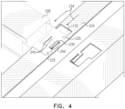
FIG. 4 shows a detail of an inner support beam in a locked position on one of the outer support beams ofFig. 2A ; -
FIG. 5 shows a mechanism which may be attached to an underside of a PV panel, for locking the PV panel to a support beam; -
FIG. 6 shows alternative shapes, by way of example, for the ferromagnetic lock flap; -
FIG. 7A shows a first detail of the mechanism ofFig. 5 ; -
Fig. 7B , shows a first detail of the mechanism ofFig. 5 with the latch shown in a semitransparent manner; -
FIG. 7C shows a two side views ofpanel locking mechanism 301 ofFigs. 5 - 7B ; -
Fig. 8 shows a detail of the mechanism ofFig. 5 ; -
Fig. 9 shows a first view of an example of a suction cup mechanism for moving the PV panel; and -
Fig. 10 shows a second view of the suction cup mechanism ofFig. 9 . - The accompanying drawings, which form a part hereof, show examples of the disclosure. It is to be understood that the examples shown in the drawings and/or discussed herein are non-exclusive and that there are other examples of how the disclosure may be practiced.
- The description below is within the context of locking/unlocking and carrying a PV panel with a glass pane. However, it will be appreciated that the present subject matter can be applied to other situations of locking and carrying other appropriate objects in accordance with the present subject matter.
- For example, other types of objects with a relatively flat surface, including other types of panels may be attached to a supporting structure/unattached and carried. These other types of panels may include, but are not limited to, a solar panel used in a water heating system, a decorative panel, a panel for a roof vent fan, etc. Similarly, a wooden or plastic surface may be locked/unlocked to/from a supporting frame using methods and systems describe below.
- In some cases, the panel has at least a portion that is magnetically neutral, so that if an object with ferromagnetic properties is placed on a first side of the panel and a magnet is placed on a second side of the panel, e.g. opposite to the first side of the panel, the object will be attracted to, and held in place by the magnetic field of, the magnet.
- Reference is now made to
Fig. 1A , which shows asupport structure 10 and locking mechanism for at least one photovoltaic (PV) panel. The support structure, presented as one possible example for a support structure, includes verticalouter support beams outer support beam 120. The example presented inFig. 1A is not meant to be limiting, and other support structures are also possible. The framework may also includeinner support beams inner support beams PV panel 100, and not at the edges of the PV panel 100 (as is the case with verticalouter support beams - A
ferromagnetic lock flap 180, adovetail latch 190, andsecond dovetail latch 197, are shown in one possible configuration as being attached to and or partly insideinner support beams ferromagnetic lock flap 180 and thedovetail latch 190 comprise portions of a PV panel locking mechanism, as will be described below, in greater detail. - Reference is now made to
Fig. 1B , which depicts a photovoltaic (PV)panel 100 resting on thesupport structure 10. Thesupport structure 10 provides a framework including verticalouter support beams outer support beam 120. Verticalouter support beams outer support beam 120 are disposed around and support an outer portion/edges of thePV panel 100.Fig. 1B presents a high-level depiction of the framework and a locking apparatus, which will be described in greater detail below, with reference toFigs. 2 - 10 . ThePV panel 100 is depicted as a frameless PV panel. However, the depiction inFig. 1B of thePV panel 100 as being a frameless PV panel is not meant to be limiting. - Vertical
outside support beams frameless PV panel 100, respectively. Horizontaloutside support beam 120 is generally aligned along a third "bottom" edge of theframeless PV panel 100, and is disposed generally perpendicularly to the verticaloutside support beams 110A and 11 0B. In this case, the first and second edges are longer than the third edge. The verticaloutside support beams outside support beam 120 as depicted inFigs. 1A and1B may be part of/attached to a larger framework of support beams for PV panels (which may be frameless PV panels, such as PV panel 100), which may be disposed in a solar energy harvesting installation. Such solar energy harvesting installations may have relatively large numbers of PV panels (e.g. tens, hundreds, or thousands of PV panels, each of the PV panels being similar to PV panel 100). Solar energy harvesting installations may be, for example, a solar energy farm, or a household solar installation, and may be found, for example, on a rooftop of a domicile. A PV panel, such asPV panel 100, will have one side (typically the side that is opposed to the support structure 10) which is photovoltaicly active and responds to sunlight by generating DC electricity, and a second side (typically, the side which is facing the support structure 10) which is photovoltaicly neutral and does not respond to sunlight. - The inner support beams 130A, 130B are substantially parallel to horizontal
outer support beam 120, and are disposed generally parallel to the third "bottom" edge of theframeless PV panel 100.Inner support beam 130A andinner support beam 130B are each typically attached on one end to verticalouter support beam 110A, and on the other end to verticalouter support beam 110B. A support beam locking mechanism, including a locking slot 170 (described below with reference toFigs. 2A and2B ) enables lockinginner support beam 130A andinner support beam 130B to interlock with verticalouter support beams - The
PV panel 100 typically includes a sheet ofglass 140, which is disposed over a plurality ofphotovoltaic cells 150. A length ofconductive material 160 electrically connects the plurality ofphotovoltaic cells 150 to each other, thereby joining the plurality ofphotovoltaic cells 150 into a string of photovoltaic cells. Apositive terminal 165P and anegative terminal 165N may be provided so that electricity generated by thePV panel 100 may be output from thePV panel 100 to a solar energy harvesting system (not shown). - As will be described below with reference to
Figs. 2A - 4 , thesupport structure 10 may be designed and built with corresponding connection elements on the inner and outer support beams which may be used to enable locking and unlocking of the support beams to and from one another. The corresponding connection elements may be part of a supportbeam locking mechanism 200, which is described below with reference toFigs. 2A - 4 . - As will be described below with reference to
Figs. 5 - 8 , a panel locking mechanism 301 (Fig. 5 ) may be used to reversibly attach the PV panel to thesupport structure 10. Thepanel locking mechanism 301 may include, for example, aferromagnetic lock flap 180/340, a tongue 370 (Fig. 7B ), and thedovetail latch 190/320. Theferromagnetic lock flap 180/340 may be arranged to help lock thePV panel 100 to the inner support beams 130A, 130B in order to keep thePV panel 100 in place. A tongue 370 (Fig. 7B ) which is actuated by theferromagnetic lock flap 180/340 may engage or disengage into thedovetail latch 190/320. Thedovetail latch 190/320 is configured to be physically attached (e.g., by glue or other appropriate adhesive) to thePV panel 100 whentongue 370 is actuated, in order to lock thePV panel 100 to inner support beams 130A, 130B. In an engaged position,ferromagnetic lock flap 180/340 causes thetongue 370 to enter thedovetail latch 190/320 through a hole in the inner support beams 130A, 130B (as shown inFig. 7C ), thereby holding thePV panel 100 locked to the inner support beams 130A, 130B. In a disengaged position, theferromagnetic lock flap 180/340 causes thetongue 370 to disengage from thedovetail latch 190/320, thereby releasing thePV panel 100 so that it is now unlocked from the inner support beams 130A, 130B. - For example, an installer may maintain the
ferromagnetic lock flap 180/340 in a disengaged position during the process of installation of thePV panel 100. Once thePV panel 100 has been installed, however, the installer may actuate theferromagnetic lock flap 180/340 to engage thetongue 370 to thedovetail latch 190/320, thereby locking thePV panel 100 to at least one of the intermediate support beams 130A, 130B. Alternatively, if, for some reason, thePV panel 100 is to be removed, for example, in order to replace thePV panel 100, then the installer may first deactivate theferromagnetic lock flap 180/340 in order to disengagetongue 370 from thedovetail latch 190/320, thereby unlocking thePV panel 100 from the inner support beams 130A, 130B, and allowing removal of thePV panel 100 from thesupport structure 10.Second dovetail latch 197 provides additional stabilization to thePV panel 100. - Once installed on the
support structure 10, one PV panel rests on the framework formed by verticalouter support beams outer support beam 120, and inner support beams 130A, 130B. The one PV panel, such asPV panel 100 depicted inFig. 1B is locked to the framework by the locking mechanism at two dovetail latches 190/320 (a first one on the left ofinner support beam 130A, and a second one diagonally opposed to the first one, on the right ofinner support beam 130B). Additionally, for further stability, two diagonally opposed second dovetail latches 197 are provided. Utilizing these four dovetails to attach thePV panel 100 to the framework provides redundancy as well. - As will be described below with reference to
Figs. 9 and10 , an unlocking/carrying mechanism may be used to help unlock thepanel locking mechanism 301 from thesupport structure 10, and to help transport/maneuver thePV panel 100. The unlocking/carrying mechanism 301 may include asuction cup mechanism 195, which is described below with reference toFigs. 9 and10 .Suction cup mechanism 195 may be attached to the sheet ofglass 140 and be used to maneuver the PV panel 100 (e.g., in order to help carry and/or adjust the PV panel to install or to remove the PV panel 100).Suction cup mechanism 195 may include a magnet (described below with reference toFig. 10 ), which may engage with and raise theferromagnetic lock flap 180/340, thereby releasing thetongue 370 from thedovetail latch 190, and unlocking/detaching thePV panel 100 from thesupport structure 10. - Reference is now made to
Figs. 2A - 4 , which shows a detail of a supportbeam locking mechanism 200 including corresponding connection elements, for connecting support beams to one another. Supportbeam locking mechanism 200 includes a first corresponding connection element/portion, which may be disposed in afirst support beam 225, and a second corresponding connection element/portion, which may be disposed in asecond support beam 228.First support beam 225 may be the same as or similar to one of the verticalouter support beams Figs. 1A and1B .Second support beam 228 may be the same as or similar to one of the inner support beams 130A, 130B ofFigs. 1A and1B . The first corresponding connection element/portion may include thelocking slot 170 with aflexible tongue 210 on thefirst support beam 225. The second corresponding connection element/portion may includetabs second support beam 228. - Reference is now made to
Fig. 2B , which shows a detail of one end of thesecond support beam 228.Fig. 2B illustrates the corresponding connection element/portion of the supportbeam locking mechanism 200 that is on thesecond support beam 228. In this case, the corresponding connection element includestabs second support beam 228. A first pair oftabs 235 extend off of sides of second support beam 228 (note that only one end ofsecond support beam 228 is shown inFig. 2B ). A second pair oftabs 245 is disposed perpendicular to and descend in a direction indicated by a z-axis, off of the first pair oftabs 235. - The corresponding connection element/portion on the
second support beam 228, in this case second pair oftabs 245, is inserted in thelocking slot 170 of thefirst support beam 225. As shown inFigs. 3 and4 , once inserted, thesecond support beam 228 may slide, in a direction indicated by a pair ofarrows 234 depicted inFigs. 3 and4 , so that thesecond support beam 228 engages aflexible tongue 210 of the supportbeam locking mechanism 200, thereby being locked in place, as will be described in greater detail below with reference toFig. 4 . - The
flexible tongue 210 may be disposed on one side of thelocking slot 170. Theflexible tongue 210 is held in place by afirst part 220, which may be fully joined at one side to thefirst support beam 225. Asecond part 230 of theflexible tongue 210 may extend along aninside edge 240 of thelocking slot 170, while not being attached along theinside edge 240 of thelocking slot 170. Accordingly, aspace 250 is created between theinside edge 240 and thesecond part 230. When thesecond support beam 228 is slid into place (as is indicated by the pair ofarrows 234 inFigs. 3 and4 ), thesecond part 230 is depressed by thesecond support beam 228. However, when thesecond support beam 228 is completely engaged in the locking slot 170 (as inFig. 4 ), theflexible tongue 210 is no longer depressed. Thesecond support beam 228 can no longer slide into the position shown inFig. 3 , as theflexible tongue 210 is now blocking such reverse motion, thereby locking thesecond support beam 228 to thefirst support beam 225. - As is shown in
Fig. 3 , one end of thesecond support beam 228 is inserted into thelocking slot 170, such that at least one tab of the second pair oftabs 245 is inserted in thespace 250 between thesecond part 230 and theinside edge 240 of thefirst support beam 225. Thesecond support beam 228 is then slid in the direction indicated by the pair ofarrows 234, into the position shown inFig. 4 .Flexible tongue 210 is depressed by thesecond support beam 228 while the action of sliding thesecond support beam 228 is in progress, so that thesecond support beam 228 depresses theflexible tongue 210. Once engaged in the position shown inFig. 4 , however, thesecond support beam 228 is blocked from returning to the position shown inFig. 3 , because theflexible tongue 210 serves to block reverse motion by theintermediate support beam 225, thereby locking thesecond support beam 228 to thefirst support beam 228. - The above description of assembly and attachment of the
intermediate support beam 225 to the verticalouter support beams outer support beam 120 is an example of one method for performing such attachment. Persons of skill in the art will understand that the above description is by way of example only, and is not meant to be limiting or excluding of any other appropriate method. - Reference is now made to
FIG. 5 , which shows apanel locking mechanism 301.Panel locking mechanism 301 includes, for example, alatch 320, aflap 330, aferromagnetic lock flap 340, and atongue 370, which will be described in greater detail below.Panel locking mechanism 301 may be attached to an underside of a PV panel, such asframeless PV panel 100, (i.e., a side which is not operative to absorb sunlight and convert the sunlight to DC electricity), for locking the PV panel to a support beam, typically an inner support beam. By way of example, thepanel locking mechanism 301 may be attached with glue or other adhesive material, which is resistant to appropriate environmental or elemental factors. For example, a glue or adhesive susceptible to extreme heat or extreme cold may not be appropriate for use in locations where such extreme temperature conditions may be prevalent. - In some cases, however, the locking mechanism described herein may be designed to lock the PV panel to the outer support beams, such as vertical
outer support beams outer support beam 120. - Inner support beam 310 (which may be the same as or similar to inner support beams 130A, 130B, and second support beam 228) interlocks with the
latch 320. Thelatch 320 may be the same as or similar to thedovetail latch 190 described above, with reference toFig. 1 . - In some aspects, the
latch 320 may be designed to have a generally dovetail-like shape, as depicted inFigs. 1 , and5 - 7B . The dovetail-like shape is used in instances when a corresponding slot (not shown) may receive the dovetail-like shaped item (in this case, the latch 320). For instance, a slot on thePV panel 100 may be shaped to receive thelatch 320. When a dovetail-like shaped item is in place, it is typically resistant to forces, which push the item out of position. It is appreciated that the depiction of thelatch 320 as having a dovetail-like shape is by way of example, and other appropriate shapes, as are known in the art, which may have their own properties, may be used for thelatch 320. - When the
locking mechanism 301 is engaged, theflap 330 engages the tongue 370 (note that inFig. 5 , thetongue 370 is mostly occluded, however, seeFigs. 7B and8 , where thetongue 370 is depicted more clearly). Thetongue 370 is raised to an engaged position or lowered to a disengaged position by the raising / loweringferromagnetic lock flap 340, which may be the same as or similar toferromagnetic lock flap 180 ofFig. 1 . Specifically, when theferromagnetic lock flap 340 is raised, thetongue 370 is in a disengaged position, and the locking mechanism is unlocked. When theferromagnetic lock flap 340 is lowered, thetongue 370 is in an engaged position, and the locking mechanism is locked. The mechanics of raising and / or lowering thetongue 370 are described below. - Note that depictions of elements in the figures may have a particular shape. By way of example,
ferromagnetic lock flap 340 is depicted as having a round shape and extending from one side of a thinner and longer element (first member 375, discussed below with reference toFigs. 6-8 ). In general, the shape of particular elements in the figures is not meant to be limiting. - Reference is now made to
Fig. 6 , which shows, alternative shapes, by way of example, for theferromagnetic lock flap 340. E.g., ferromagnetic lock flap might be ahexagon 346, or anoctagon 348, or some irregular shape (not depicted). Furthermore, instead offerromagnetic lock flap 340 being disposed at one side of thefirst member 375, theferromagnetic lock flap 340 and thefirst member 375 might both be one largerectangular flap 347 orovoid flap 349. Other examples, not provided here, where different shapes of the elements depicted in the figures might have the same functionality will be apparent to persons of skill in the art. - Reference is now made to
FIG. 7A which shows a first detail of thepanel locking mechanism 301 ofFig. 5 . Reference is also made toFIG. 7B , which shows a second detail of thepanel locking mechanism 301 ofFig. 5 . InFig. 7B , thelatch 320 is shown in a semitransparent manner, so that thetongue 370 is no longer occluded by thelatch 320 and theflap 330. Theferromagnetic lock flap 340 has anelbow 350 forming a substantially 90 degree (i.e., right) angle between afirst member 375, which terminates at theferromagnetic lock flap 340 on one end and theelbow 350 on the other end, and asecond member 380. Thesecond member 380 includes ahinge 360 and thetongue 370, which protrudes off of one end of thesecond member 380 at a substantially 90 degree angle. Accordingly, thefirst member 375 and thesecond member 380 are hingedly attached. -
Ferromagnetic lock flap 340 by design comprises at one end a member, which, due to gravity, weighs downfirst member 375. Whenferromagnetic lock flap 340 is in a 'down position,' i.e., in an `engaged position/state,' and is not actuated,elbow 350 is naturally pushed up by the weight offerromagnetic lock flap 340 and thefirst member 375. Whenelbow 350 is pushed up, then it applies an upward force onsecond member 380. Accordingly, a center of gravity of theferromagnetic lock flap 340 is located in thesecond member 380, as the upward force is applied to thehinge 360, thetongue 370 is pushed up, thereby engaging with theflap 330. Accordingly, thepanel locking mechanism 301 ofFigs. 5 - 7B will be locked, and thePV panel 100 will be secured to the support structure 10 (Fig. 1A ). - On, the other hand, when the
ferromagnetic lock flap 340 is in an `up position,' i.e., in a 'disengaged position/state,' (meaning that theferromagnetic lock flap 340 is actuated, and is not weighing down the first member 375) minimal upward force (if any) may be applied at theelbow 350, and thus, thesecond member 380 is not pushed up. Accordingly, thetongue 370 is not pushed up by thehinge 360, and thetongue 370 does not engage with theflap 330. In such a case, thepanel locking mechanism 301 ofFigs. 5 - 7B is not locked, and thePV panel 100 will not be secured to the support structure10 (Fig. 1A ). - Reference is now made to
Fig. 7C , which shows a two side views ofpanel locking mechanism 301 ofFigs. 5 - 7B . In the depiction on the top ofFig. 7C , the locking mechanism is engaged, and tongue 370-E appears occulted, as it is within one of the intermediate support beams, such as intermediate support beams 130A, 130B. Ferromagnetic lock flap 340-E is depicted as being in its engaged position. In the depiction on the bottom ofFig. 7C , the locking mechanism is disengaged, and tongue 370-D can be seen, beneath one of the intermediate support beams, such as intermediate support beams 130A, 130B. Ferromagnetic lock flap 340-D is depicted as being in its disengaged position. - Reference is now made to
Fig. 8 , which shows a detail of thepanel locking mechanism 301 ofFig. 5 . Although thepanel locking mechanism 301 is described in detail above, an additional feature which may be implemented in thepanel locking mechanism 301 not discussed above is shown inFig. 8 . Optionally, aspring 390 may be disposed on thesecond member 380 on a side of thehinge 360. Thespring 390 may be positioned/oriented in a way (in relation to thesecond member 380/hinge 360) which will result in thespring 390, when not compressed, exerting downward force, and therefore adding additional force on a distal side of thehinge 360. This additional force, applied when theferromagnetic lock flap 340 is disengaged, and thus thetongue 370 is engaged, is applied so as to push thetongue 370 up (i.e., engaged with the flap 330), in the absence of any other factors which might otherwise cause thetongue 370 to disengage from theflap 330. - Reference is now made to
Fig. 9 , which shows a first view of an example of asuction cup mechanism 400 for moving the PV panel (such asPV panel 100 ofFig. 1B ). Reference is also made toFig. 10 , which shows a second view of thesuction cup mechanism 400. As was noted above, when installing or replacingPV panel 100 on thesupport structure 10/the various support beams (such as verticalouter support beams outer support beam 120, inner support beams 130A, 130B, and so forth), thesuction cup mechanism 400 may be attached to the glass of the panel by suction, thereby enabling the glass to be lifted or put in place. Because of the construction of thePV panel 100, when the glass is lifted up, the entire PV panel is lifted up along with the glass. - The view of
Fig. 9 is a view of the top of thesuction cup mechanism 400 to be held by a user when carrying the glass/panel, and the view inFig. 10 is a view of the bottom of thesuction cup mechanism 400 to be attached to the glass/panel, as will be elaborated on herein below. - The
suction cup mechanism 400 includes ahandle 405, by which an installer, for instance, is able to hold thesuction cup mechanism 400. When thesuction cup mechanism 400 is attached to theglass 140 of thePV panel 100, the installer is able to maneuver thePV panel 100, for example to place thePV panel 100 on thesupport structure 10/framework of verticalouter support beams outer support beam 120 as described above with reference toFigs. 1A and1B . Thehandle 405 is attached to one or moresuction cup cases 410. Eachsuction cup case 410 holds at least onesuction cup 420 in place. One ormore suction cups 420 are included in thesuction cup mechanism 400. In the example ofFigs. 9 and10 , there are twosuction cups 420 on opposite ends of thehandle 405. In cases where there are asingle suction cup 420, or three ormore suction cups 420, they may be configured in an appropriate manner. Thehandle 405 is typically positioned so that weight of the glass (and, by extension, the PV panel 100) is equally distributed among the suction cups, when there is more than one suction cup) when a pane of glass, such as theglass 140, is attached to thesuction cups 420. The suction cups 420 may be activated so that they form a vacuum and apply suction to theglass 140 of thePV panel 100 by raising or lowering a suctioncup deactivation element 430, depicted aslevers 430. Suction cups 420 may be deactivated by using suctioncup deactivation element 430 to release thesuction cups 420 by removing the vacuum, thereby releasing the suction cup mechanism fromglass 140 andpanel 100. - A
magnet 440 is embedded between at least one of thesuction cups 420 and its correspondingsuction cup case 410. Themagnet 440 may be a permanent magnet or an electromagnet. The permanent magnet may be a magnet having appropriate ferromagnetic properties, such as an iron magnet, a nickel magnet, a cobalt magnet, or a rare earth magnet, such as a neodymium or a samarium-cobalt magnet. If themagnet 440 is an electromagnet, then, for instance, a button or a lever (not shown) may be used to activate / deactivate the electromagnet using an appropriate electrical circuit. The button or the lever may be provided in an appropriate location, for example, on the body of thesuction cup mechanism 400, e.g. in a proximity to handle 405 so that the button/lever can be actuated/deactivated while holding thehandle 405. A battery (not shown) may be disposed within the body of thesuction cup mechanism 400. The battery provides an electrical current to power the electromagnet when the electromagnet is activated. Additionally, instead of a single magnet, as depicted inFig. 10 , a plurality of magnets may be arranged in an appropriate pattern. As one non-limiting example, a disk, comprising 6, 8, or 10 rectangular or circular shaped magnets radially disposed around a central point in the disk may be disposed beneathsuction cup 420. -
Fig. 9 does not illustrate a panel, but apanel 100 may be disposed betweenpanel locking mechanism 301 andsuction cup mechanism 400 as illustrated inFig. 1B . - As can be seen in
Fig. 9 , when thesuction cup mechanism 400 is aligned over theferromagnetic lock flap 340, the magnetic properties of theferromagnetic lock flap 340 are such that theferromagnetic lock flap 340 is attracted to themagnet 440. As described above, with reference toFigs. 5-8 , when theferromagnetic lock flap 340 is in the raised "up position" or "disengaged position/state",tongue 370 is disengaged from theflap 330, and panel-lockingmechanism 301 is in an unlocked state, allowing thepanel 100 to be maneuvered. Thesuction cup mechanism 440 may also be secured topanel 100 to allow the carrying ofpanel 100 while thepanel 100 is unlocked from thesupport structure 10. - The panel may then be moved. After the panel has been moved, suction cup mechanism may be deactivated. Then the
magnet 440 can be brought out of alignment with theferromagnetic lock flap 340, thereby once again locking thepanel locking mechanism 301, and, for example, securing thepanel 100 to thesupport structure 10. - Alternatively, if the
magnet 440 is an electromagnet, then when the electromagnet is powered on, theferromagnetic lock flap 340 is attracted to themagnet 440. In such a case thepanel locking mechanism 301 will be in an "up position" or "disengaged position", and thetongue 370 will be disengaged fromflap 330, thereby unlocking thepanel locking mechanism 440, and unlockingpanel 100 fromsupport structure 10. In such a case, if thesuction cup mechanism 400 is also secured to thepanel 100, then it may be used to carry/maneuver theunlocked panel 100. When themagnet 440 is removed (either by physically moving themagnet 440 out of alignment withferromagnetic lock flap 340 or by turning off the electromagnet), then theferromagnetic lock flap 340 will fall into a "down position" or "engaged position" (e.g. due to the weight offerromagnetic lock flap 340 and the effect of gravity on ferromagnetic lock flap 340) and thetongue 370 will thereby engage theflap 330. At such time, thePV panel 100 will, effectively, be locked to thesupport structure 10, e.g., intermediate support beams 130A, 130B. In such a case, if thesuction cup mechanism 400 is no longer secured to thepanel 100, then thesuction cup mechanism 400 may be removed from the lockedpanel 100 - In some aspects, the mechanism described above may be modified so that the latch is engaged and locked when the ferromagnetic flap is in the engaged position and is disengaged when the when the ferromagnetic flap is in the disengaged position. In such an aspect, by way of example, an electromagnet may be placed on the side of the panel away from the ferromagnetic flap, thereby drawing the ferromagnetic flap towards the panel, ensuring that the ferromagnetic flap, and thus the latch is in the engaged position. In such an aspect, the electromagnet may receive power from the solar panel (e.g., via a power converter connected to the solar panel), from a battery, from an inverter, or from an alternative power source.
- The invention further discloses embodiments and features in the following clauses:
- Clause 1: A device comprising a ferromagnetic lock flap having an engaged position and a disengaged position; the ferromagnetic lock flap comprising: a first portion with ferromagnetic properties; a second portion configured to engage with a latch when in the engaged position; and a hinge that hingedly connects the first portion and the second portion; wherein the device comprises a locking mechanism disposed on a first side of a panel to be locked in place, the panel being magnetically neutral; wherein when the ferromagnetic lock flap is in the engaged position, the first portion is in a first position that forces the hingedly connected second portion to engage with the latch, thereby unlocking the locking mechanism; and when the ferromagnetic lock flap is in the disengaged position, the first portion is in a second position that forces the hingedly connected second portion to disengage from the latch, thereby locking the locking mechanism, and wherein placing a magnet on a second side of the panel causes the ferromagnetic lock flap to enter the disengaged position, thereby unlocking the locking mechanism.
- Clause 2: The device of clause 1, wherein the second side of the panel is photovoltaicly active and the first side of the panel is photovoltaicly neutral.
- Clause 3: The device of clause 1 or 2, wherein the panel comprises a solar panel, and the locking mechanism locks the solar panel to a support structure.
- Clause 4: The device of clause 3, wherein the solar panel is used for generating electricity.
- Clause 5: The device of clause 3, wherein the solar panel is used for conversion of sunlight into heat for water heating.
- Clause 6. The device of clause 3, wherein the solar panel comprises a frameless solar panel.
- Clause 7: The device of any of the preceding clauses, wherein the panel comprises a decorative panel, and the locking mechanism locks the decorative panel to a support structure.
- Clause 8: The device of any of the preceding clauses, wherein the panel comprises a roof vent fan, and the locking mechanism locks the roof vent fan to a support structure.
- Clause 9. The device of any of the preceding clauses, wherein the first portion of the ferromagnetic lock flap has a greater weight than the second portion of the ferromagnetic lock flap.
-
Clause 10. The device of clause 9 wherein the weight of the first portion applies a force in the direction of the panel on the second portion, thereby positioning the ferromagnetic lock flap in the engaged position and causing the second portion to engage the latch and lock the panel. - Clause 11. The device of any of the preceding clauses, wherein, upon the ferromagnetic lock flap entering the engaged position, the first portion applies pressure on the hingedly attached second portion, thereby causing the second portion to be engaged in the latch.
- Clause 12. The device of clause 11, wherein, upon the ferromagnetic lock flap entering the disengaged position, the first portion ceases to apply pressure on the hingedly attached second portion, thereby causing the second portion to be disengaged from the latch.
- Clause 13. The device of any of the preceding clauses, wherein the first portion is attached to a first member that comprises a first part and a second part, the first part attached to the first portion and comprising a larger surface area than a surface area of the second part, the second part comprising an elongated extension member which is longer than the first part, and is attached at one end to the first part.
- Clause 14. The device of clause 13, wherein the first member is attached to a second member, the second member being attached to the hinge, and the second member being attached at one end to the first member and at another end to the second portion of the ferromagnetic lock flap.
- Clause 15. The device of clause 14, wherein the first member and the second member form a substantially right angle with one another.
- Clause 16. The device of clause 14 or 15, wherein a center of gravity of the ferromagnetic lock flap is located in the second member.
- Clause 17. The device of any of clauses 14 to 16, wherein a spring is disposed at a joint formed between the first member and the second member, the spring applying force in a direction away from the joint, thereby positioning the ferromagnetic lock flap in the engaged position.
- Clause 18. The device of any of the preceding clauses, wherein the magnet comprises an electromagnet.
- Clause 19. The device of any of the preceding clauses, wherein the magnet is disposed in a suction cup mechanism.
- Clause 20. A device for lifting an object with a flat surface, the device comprising: a suction cup mechanism; a handle fixedly attached to the suction cup mechanism; the suction cup mechanism comprising: a first suction cup actuated by an actuation element, wherein actuation of the actuation element causes the first suction cup to apply suction to a first side of the object; and a magnet attached to the first suction cup, wherein the magnet is operative to attract a ferromagnetic lock flap disposed on a second side of the object, thereby disengaging a lock actuated by the ferromagnetic lock flap, and releasing the object from the lock.
- Clause 21. The device of clause 20 wherein the actuation element comprises one of a lever or a button.
- Clause 22. The device of clause 20 or 21, wherein disengaging the lock unlocks the object from a support structure.
- Clause 23. The device of any of clauses 20 to 22, wherein the suction cup mechanism comprises two or more suction cups.
- Clause 24. The device of any of clauses 20 to 23, wherein the magnet comprises an electromagnet.
- Clause 25. The device of clause 24, wherein an actuator disposed on the handle causes application of an electric current to the electromagnet.
- Clause 26. The device of clause 24, or 25 wherein the actuator comprises one of a lever or a button.
- Clause 27. The device of any of clauses 24 to 26, wherein actuating the actuator results in application of an electric current to the electromagnet.
- Clause 28. The device of any of clauses 20 to 27, wherein the object comprises a solar panel.
- Clause 29. The device of clause 28, wherein the solar panel comprises a frameless solar panel.
- Clause 30. The device of any of clauses 20 to 29, wherein the object comprises a decorative panel.
- Clause 31. The device of any of clauses 20 to 30, wherein the object comprises a panel for a roof vent fan.
- Clause 32. A device comprising: a ferromagnetic lock flap having an engaged position and a disengaged position; the ferromagnetic lock flap comprising: a first portion with ferromagnetic properties; a second portion configured to engage with a latch when in the engaged position; and a hinge that hingedly connects the first portion and the second portion; and a member attached at one end to the first portion and at a second end being hingedly attached to the latch; wherein the device comprises a locking mechanism disposed on a first side of a panel to be locked in place, the panel being magnetically neutral; wherein when the ferromagnetic lock flap is in the engaged position, the first portion is in a first position that forces the hingedly connected second portion to engage with the latch, thereby unlocking the locking mechanism; and when the ferromagnetic lock flap is in the disengaged position, the first portion is in a second position that forces the hingedly connected second portion to disengage from the latch, thereby locking the locking mechanism, and wherein placing a magnet on a second side of the panel causes the ferromagnetic lock flap to enter the disengaged position, thereby unlocking the locking mechanism.
- Aspects of the invention include:
- A magnetic locking mechanism which is engaged by engaging a magnet.
- A magnetic locking mechanism which is disengaged by engaging a magnet.
- A magnetic locking mechanism which is engaged by disengaging a magnet.
- A magnetic locking mechanism which is disengaged by disengaging a magnet.
- Further disclosed are the following examples:
- Example 1. A device comprising a ferromagnetic lock flap having an engaged position and a disengaged position; the ferromagnetic lock flap comprising: a first portion with ferromagnetic properties; a second portion configured to engage with a latch when in the engaged position; and a hinge that hingedly connects the first portion and the second portion; wherein the device comprises a locking mechanism disposed on a first side of a panel to be locked in place, at least a portion of the panel being magnetically neutral; wherein when the ferromagnetic lock flap is in the engaged position, the first portion is in a first position that forces the hingedly connected second portion to engage with the latch; and when the ferromagnetic lock flap is in the disengaged position, the first portion is in a second position that forces the hingedly connected second portion to disengage from the latch, thereby locking the locking mechanism, and wherein placing a magnet on a second side of the panel causes the ferromagnetic lock flap to enter the disengaged position.
- Example 2. The device of example 1, wherein when the ferromagnetic lock flap is in the engaged position, the locking mechanism is unlocked.
- Example 3. The device of example 1 or example 2, wherein when the ferromagnetic lock flap is in the disengaged position, the locking mechanism is locked.
- Example 4. The device of any of the preceding examples, wherein at least one of: placing a magnet on a second side of the panel unlocks the locking mechanism; the magnet comprises an electromagnet; and the magnet is disposed in a suction cup mechanism.
- Example 5. The device of any of the preceding examples, wherein the second side of the panel is photovoltaicly active and the first side of the panel is photovoltaicly neutral.
- Example 6. The device of any of the preceding examples, wherein the panel comprises a solar panel, and the locking mechanism locks the solar panel to a support structure.
- Example 7. The device of example 6, wherein at least one of: the solar panel is used for generating electricity; and the solar panel is used for conversion of sunlight into heat for water heating; and, wherein the solar panel comprises a frameless solar panel.
- Example 8. The device of any of examples 1 to 4, wherein the panel comprises a decorative panel, and the locking mechanism locks the decorative panel to a support structure.
- Example 9. The device of any of examples 1 to 4, wherein the panel comprises a roof vent fan, and the locking mechanism locks the roof vent fan to a support structure.
- Example 10. The device of any of the preceding examples, wherein the first portion of the ferromagnetic lock flap has a greater weight than the second portion of the ferromagnetic lock flap and wherein the weight of the first portion applies a force in the direction of the panel on the second portion, thereby positioning the ferromagnetic lock flap in the engaged position and causing the second portion to engage the latch and lock the panel.
- Example 11. The device of any of the preceding examples, wherein, upon the ferromagnetic lock flap entering the engaged position, the first portion applies pressure on the hingedly attached second portion, thereby causing the second portion to be engaged in the latch.
- Example 12. The device of example 11, wherein, upon the ferromagnetic lock flap entering the disengaged position, the first portion ceases to apply pressure on the hingedly attached second portion, thereby causing the second portion to be disengaged from the latch.
- Example 13. The device of any of the preceding examples, wherein the first portion is attached to a first member that comprises a first part and a second part, the first part attached to the first portion and comprising a larger surface area than a surface area of the second part, the second part comprising an elongated extension member which is longer than the first part, and is attached at one end to the first part.
- Example 14. The device of example 13, wherein the first member is attached to a second member, the second member being attached to the hinge, and the second member being attached at one end to the first member and at another end to the second portion of the ferromagnetic lock flap.
- Example 15. The device of example 14, wherein at least one of: the first member and the second member form a substantially right angle with one another; a center of gravity of the ferromagnetic lock flap is located in the second member; and a spring is disposed at a joint formed between the first member and the second member, the spring applying force in a direction away from the joint, thereby positioning the ferromagnetic lock flap in the engaged position.
- Although examples are described above, features and/or steps of those examples may be combined, divided, omitted, rearranged, revised, and/or augmented in any desired manner. Various alterations, modifications, and improvements will readily occur to those skilled in the art. Such alterations, modifications, and improvements are intended to be part of this description, though not expressly stated herein, and are intended to be within the spirit and scope of the disclosure. Accordingly, the foregoing description is by way of example only, and is not limiting.
Claims (15)
- An apparatus comprising:a suction cup mechanism comprising:a handle;a magnet;a suction cup case attached to the handle;a suction cup held by the suction cup case; anda suction cup activation element comprising a first state and a second state, wherein in the first state the suction cup activation element is configured to cause the suction cup to form a vacuum with a flat surface opposing the suction cup, and wherein in the second state to release the vacuum, andwherein the magnet is configured to activate a ferromagnetic lock distal to the flat surface when the suction cup activation element is in the first state, thereby reversibly attaching a panel to a support structure, wherein at least a portion of the panel is magnetically neutral.
- The apparatus of claim 1, wherein the ferromagnetic lock comprises an engaged position and a disengaged position, wherein the ferromagnetic lock comprises:a first portion with ferromagnetic properties;a second portion configured to engage with a latch when in the engaged position;a hinge that hingedly connects the first portion and the second portion; anda locking mechanism disposed on a first side of a photovoltaic panel to be locked in place, at least a portion of the photovoltaic panel being magnetically neutral,wherein when the ferromagnetic lock is in the engaged position, the first portion is in a first position that forces the hingedly connected second portion to engage with the latch; andwhen the ferromagnetic lock is in the disengaged position, the first portion is in a second position that forces the hingedly connected second portion to disengage from the latch, thereby locking the locking mechanism.
- The apparatus of any one of claims 1 or 2 wherein the flat surface comprises a front surface of a photovoltaic panel.
- The apparatus of any one of claims 1 to 3 further comprising a second suction cup and second suction cup case, and wherein in the first state the suction cup activation element is configured to cause the second suction cup to form a second vacuum with a flat surface opposing the second suction cup, and wherein in the second state to release the second vacuum.
- The apparatus of any one of claims 1 to 4 wherein the magnet comprises an electromagnet, wherein the suction cup mechanism further comprises a button or a lever and a battery operative to activate the electromagnet.
- The apparatus of any one of claims 1 to 5 wherein the magnet comprises a permanent magnet.
- A system comprising:a suction cup mechanism comprising:a handle,a magnet,a suction cup case attached to the handle,a suction cup held by the suction cup case, anda suction cup activation element comprising a first state and a second state,wherein in the first state the suction cup activation element is configured to cause the suction cup to form a vacuum with a flat surface opposing the suction cup, andwherein in the second state to release the vacuum, wherein the magnet is configured to activate a ferromagnetic lock distal to the flat surface when the suction cup activation element is in the first state; and
the ferromagnetic lock comprising:a first portion with ferromagnetic properties;a second portion configured to engage with a latch when in an engaged position;a hinge that hingedly connects the first portion and the second portion; anda locking mechanism disposed on a first side of a photovoltaic panel to be locked in place, at least a portion of the photovoltaic panel being magnetically neutral,wherein the ferromagnetic lock comprises an engaged position and a disengaged position,wherein when the ferromagnetic lock is in the engaged position, the first portion is in a first position that forces the hingedly connected second portion to engage with the latch, andwhen the ferromagnetic lock is in the disengaged position, the first portion is in a second position that forces the hingedly connected second portion to disengage from the latch, thereby locking the locking mechanism. - The system of claim 7 wherein the flat surface comprises a front surface of a photovoltaic panel.
- The system of any of claims 7 to 8 wherein the suction cup mechanism further comprises a second suction cup and second suction cup case, and wherein in the first state the suction cup activation element is configured to cause the second suction cup to form a second vacuum with the flat surface opposing the second suction cup, and wherein in the second state to release the second vacuum.
- The system of any of claims 7 to 9 wherein the magnet comprises an electromagnet, wherein the suction cup mechanism further comprises a button or a lever and a battery operative to activate the electromagnet.
- The system of any of claims 7 to 10 wherein the magnet comprises a permanent magnet.
- The system of any of claims 7 to 11 wherein the flat surface comprises a front surface of a photovoltaic panel.
- The system of any of claims 7 to 12, further comprising a solar panel, wherein the flat surface is the front surface of the solar panel, and the locking mechanism locks the solar panel to a support structure.
- The system of any of claims 13, wherein at least one of:the solar panel is used for generating electricity; andthe solar panel is used for conversion of sunlight into heat for water heating.
- The system any of claims 13 to 14, further comprising an electromagnet configured to be placed on a second side of the solar panel to unlock the locking mechanism.
Applications Claiming Priority (2)
| Application Number | Priority Date | Filing Date | Title |
|---|---|---|---|
| US201962910026P | 2019-10-03 | 2019-10-03 | |
| EP20199915.8A EP3800784B1 (en) | 2019-10-03 | 2020-10-02 | System and method for attaching panels |
Related Parent Applications (1)
| Application Number | Title | Priority Date | Filing Date |
|---|---|---|---|
| EP20199915.8A Division EP3800784B1 (en) | 2019-10-03 | 2020-10-02 | System and method for attaching panels |
Publications (2)
| Publication Number | Publication Date |
|---|---|
| EP4297271A2 true EP4297271A2 (en) | 2023-12-27 |
| EP4297271A3 EP4297271A3 (en) | 2024-04-03 |
Family
ID=72744685
Family Applications (2)
| Application Number | Title | Priority Date | Filing Date |
|---|---|---|---|
| EP20199915.8A Active EP3800784B1 (en) | 2019-10-03 | 2020-10-02 | System and method for attaching panels |
| EP23208312.1A Withdrawn EP4297271A3 (en) | 2019-10-03 | 2020-10-02 | System and method for attaching panels |
Family Applications Before (1)
| Application Number | Title | Priority Date | Filing Date |
|---|---|---|---|
| EP20199915.8A Active EP3800784B1 (en) | 2019-10-03 | 2020-10-02 | System and method for attaching panels |
Country Status (3)
| Country | Link |
|---|---|
| US (3) | US11293174B2 (en) |
| EP (2) | EP3800784B1 (en) |
| CN (1) | CN112615586A (en) |
Families Citing this family (3)
| Publication number | Priority date | Publication date | Assignee | Title |
|---|---|---|---|---|
| EP3800784B1 (en) * | 2019-10-03 | 2023-11-08 | Solaredge Technologies Ltd. | System and method for attaching panels |
| US20240229479A1 (en) * | 2023-01-10 | 2024-07-11 | Greg Hyde HRYNIEWICZ | Framing system including tubes joined with slots, hooks and wedges integrated into the tubes |
| US20250309815A1 (en) * | 2024-03-28 | 2025-10-02 | Johnathan O' Farrell | Solar panel mounting assembly |
Family Cites Families (18)
| Publication number | Priority date | Publication date | Assignee | Title |
|---|---|---|---|---|
| US5738130A (en) * | 1997-01-06 | 1998-04-14 | Thomas; William | Vehicle supported tent |
| US6899635B2 (en) * | 2003-02-26 | 2005-05-31 | Robert Nadratowski | Device for use with a golf club to pick up objects |
| US20080173138A1 (en) * | 2006-08-15 | 2008-07-24 | Dayton Douglas C | Systems and methods of a vacuum cup bulb changer power tool system with interchangeable functional attachments |
| US20090249705A1 (en) * | 2006-12-04 | 2009-10-08 | Trufig | Mounting Receivers with Spackling Rim Gradient |
| US8281542B2 (en) * | 2006-09-11 | 2012-10-09 | Dana Innovations | Mechanisms for locking and removing flush mounted inserts |
| US9321583B2 (en) * | 2010-05-24 | 2016-04-26 | Opterra Energy Services, Inc. | Pallet assembly for transport of solar module array pre-assembly |
| US20120233940A1 (en) * | 2010-07-29 | 2012-09-20 | John Perkins | Mechanical photovoltaic module cartridge and method of construction |
| US20150237750A1 (en) * | 2011-09-21 | 2015-08-20 | The Joy Factory, Inc. | Detachable mounting systems for electronic devices |
| US8925881B2 (en) * | 2012-05-28 | 2015-01-06 | Anna Genevieve Diatzikis | Magnetic mount |
| CN203455722U (en) * | 2013-04-18 | 2014-02-26 | 飞利浦(中国)投资有限公司 | Self-rotation mechanism driven by gravity, solar panel and streetlamp power supply |
| FR3020797A1 (en) * | 2014-05-12 | 2015-11-13 | Airbus Helicopters | FIXING DEVICE FOR ATTACHING A PANEL TO A STRUCTURE, AND AIRCRAFT |
| US20200266757A1 (en) * | 2015-08-11 | 2020-08-20 | Smash Solar, Inc. | Interlocking, Preassembled Solar Panel Module System and Installation Method |
| US20180195770A1 (en) * | 2017-01-09 | 2018-07-12 | David Lynn | Panels with Magnetically-Controlled Connectors and Methods of Use |
| US20180195771A1 (en) * | 2017-01-09 | 2018-07-12 | David Lynn | Arrays with Panels Having Magnetically-Controlled Connectors for Attachment to a Support Member |
| US10371185B2 (en) * | 2017-01-09 | 2019-08-06 | David Lynn | Magnetically-controlled connectors and methods of use |
| US10155319B2 (en) * | 2017-03-28 | 2018-12-18 | David Lynn | Tools for actuating magnetically-controlled connectors and methods of use |
| AU2018276083A1 (en) * | 2017-05-29 | 2019-12-12 | Jaroslav Chorny | Magnetic self-locking fastening device with remote release |
| EP3800784B1 (en) * | 2019-10-03 | 2023-11-08 | Solaredge Technologies Ltd. | System and method for attaching panels |
-
2020
- 2020-10-02 EP EP20199915.8A patent/EP3800784B1/en active Active
- 2020-10-02 US US17/061,637 patent/US11293174B2/en active Active
- 2020-10-02 EP EP23208312.1A patent/EP4297271A3/en not_active Withdrawn
- 2020-10-09 CN CN202011072918.9A patent/CN112615586A/en active Pending
-
2022
- 2022-02-25 US US17/680,575 patent/US11891795B2/en active Active
-
2023
- 2023-12-21 US US18/392,131 patent/US20240200323A1/en not_active Abandoned
Also Published As
| Publication number | Publication date |
|---|---|
| EP3800784B1 (en) | 2023-11-08 |
| EP3800784A1 (en) | 2021-04-07 |
| US11293174B2 (en) | 2022-04-05 |
| US20240200323A1 (en) | 2024-06-20 |
| EP4297271A3 (en) | 2024-04-03 |
| US11891795B2 (en) | 2024-02-06 |
| CN112615586A (en) | 2021-04-06 |
| US20210102370A1 (en) | 2021-04-08 |
| US20220235544A1 (en) | 2022-07-28 |
Similar Documents
| Publication | Publication Date | Title |
|---|---|---|
| US20240200323A1 (en) | System and Method for Attaching Panels | |
| JP5628162B2 (en) | Solar power module | |
| JP5662466B2 (en) | Replaceable roof photovoltaic panels | |
| US7850476B2 (en) | Low profile solar laminate connector assembly | |
| JP5934091B2 (en) | Solar module mounting apparatus and installation method | |
| EP4145059A1 (en) | Solar module mounting system | |
| US20150107651A1 (en) | Solar panel mechanical connector and frame | |
| JP2011526741A (en) | Photovoltaic module kit with connector assembly for non-penetrating array installation | |
| JP2017163830A (en) | Panel support device | |
| KR101207236B1 (en) | Photovoltaic power generating apparatus | |
| US11463044B2 (en) | Corner connector for photovoltaic module frame | |
| WO2025042720A1 (en) | Solar module washer clip | |
| EP3928427A1 (en) | Solutions for photovoltaic modules with integrated mounting systems | |
| CN103662106B (en) | A kind of replaceable module locking-unlocking device with shield structure function | |
| US10371185B2 (en) | Magnetically-controlled connectors and methods of use | |
| US8962973B2 (en) | Mounting interface for a photovoltaic module | |
| JP6562529B1 (en) | Solar power plant | |
| US20180195770A1 (en) | Panels with Magnetically-Controlled Connectors and Methods of Use | |
| AU2024345875A1 (en) | Pv module conveyance system and methods | |
| US20180195771A1 (en) | Arrays with Panels Having Magnetically-Controlled Connectors for Attachment to a Support Member | |
| KR102609825B1 (en) | Dual position mount for power electronic devices | |
| KR102185391B1 (en) | Photovoltaic cell module with smooth attached to outer surface of building structure to ensure installation convenience and photoelectric efficiency | |
| JPH10205804A (en) | Air conditioner | |
| CN202167503U (en) | Photovoltaic module |
Legal Events
| Date | Code | Title | Description |
|---|---|---|---|
| PUAI | Public reference made under article 153(3) epc to a published international application that has entered the european phase |
Free format text: ORIGINAL CODE: 0009012 |
|
| STAA | Information on the status of an ep patent application or granted ep patent |
Free format text: STATUS: REQUEST FOR EXAMINATION WAS MADE |
|
| 17P | Request for examination filed |
Effective date: 20231107 |
|
| AC | Divisional application: reference to earlier application |
Ref document number: 3800784 Country of ref document: EP Kind code of ref document: P |
|
| AK | Designated contracting states |
Kind code of ref document: A2 Designated state(s): AL AT BE BG CH CY CZ DE DK EE ES FI FR GB GR HR HU IE IS IT LI LT LU LV MC MK MT NL NO PL PT RO RS SE SI SK SM TR |
|
| P01 | Opt-out of the competence of the unified patent court (upc) registered |
Effective date: 20231228 |
|
| REG | Reference to a national code |
Ref country code: DE Ref legal event code: R079 Free format text: PREVIOUS MAIN CLASS: H02S0030100000 Ipc: H02S0020200000 |
|
| PUAL | Search report despatched |
Free format text: ORIGINAL CODE: 0009013 |
|
| AK | Designated contracting states |
Kind code of ref document: A3 Designated state(s): AL AT BE BG CH CY CZ DE DK EE ES FI FR GB GR HR HU IE IS IT LI LT LU LV MC MK MT NL NO PL PT RO RS SE SI SK SM TR |
|
| RIC1 | Information provided on ipc code assigned before grant |
Ipc: H02S 30/10 20140101ALI20240228BHEP Ipc: H02S 20/20 20140101AFI20240228BHEP |
|
| STAA | Information on the status of an ep patent application or granted ep patent |
Free format text: STATUS: THE APPLICATION HAS BEEN WITHDRAWN |
|
| 18W | Application withdrawn |
Effective date: 20250930 |