EP4297250A1 - Motor - Google Patents
Motor Download PDFInfo
- Publication number
- EP4297250A1 EP4297250A1 EP22756507.4A EP22756507A EP4297250A1 EP 4297250 A1 EP4297250 A1 EP 4297250A1 EP 22756507 A EP22756507 A EP 22756507A EP 4297250 A1 EP4297250 A1 EP 4297250A1
- Authority
- EP
- European Patent Office
- Prior art keywords
- bearing
- shaft
- disposed
- housing
- motor
- Prior art date
- Legal status (The legal status is an assumption and is not a legal conclusion. Google has not performed a legal analysis and makes no representation as to the accuracy of the status listed.)
- Pending
Links
Images





Classifications
-
- H—ELECTRICITY
- H02—GENERATION; CONVERSION OR DISTRIBUTION OF ELECTRIC POWER
- H02K—DYNAMO-ELECTRIC MACHINES
- H02K5/00—Casings; Enclosures; Supports
- H02K5/04—Casings or enclosures characterised by the shape, form or construction thereof
- H02K5/16—Means for supporting bearings, e.g. insulating supports or means for fitting bearings in the bearing-shields
- H02K5/173—Means for supporting bearings, e.g. insulating supports or means for fitting bearings in the bearing-shields using bearings with rolling contact, e.g. ball bearings
- H02K5/1732—Means for supporting bearings, e.g. insulating supports or means for fitting bearings in the bearing-shields using bearings with rolling contact, e.g. ball bearings radially supporting the rotary shaft at both ends of the rotor
-
- F—MECHANICAL ENGINEERING; LIGHTING; HEATING; WEAPONS; BLASTING
- F16—ENGINEERING ELEMENTS AND UNITS; GENERAL MEASURES FOR PRODUCING AND MAINTAINING EFFECTIVE FUNCTIONING OF MACHINES OR INSTALLATIONS; THERMAL INSULATION IN GENERAL
- F16C—SHAFTS; FLEXIBLE SHAFTS; ELEMENTS OR CRANKSHAFT MECHANISMS; ROTARY BODIES OTHER THAN GEARING ELEMENTS; BEARINGS
- F16C23/00—Bearings for exclusively rotary movement adjustable for aligning or positioning
- F16C23/06—Ball or roller bearings
- F16C23/08—Ball or roller bearings self-adjusting
- F16C23/082—Ball or roller bearings self-adjusting by means of at least one substantially spherical surface
- F16C23/086—Ball or roller bearings self-adjusting by means of at least one substantially spherical surface forming a track for rolling elements
-
- F—MECHANICAL ENGINEERING; LIGHTING; HEATING; WEAPONS; BLASTING
- F16—ENGINEERING ELEMENTS AND UNITS; GENERAL MEASURES FOR PRODUCING AND MAINTAINING EFFECTIVE FUNCTIONING OF MACHINES OR INSTALLATIONS; THERMAL INSULATION IN GENERAL
- F16C—SHAFTS; FLEXIBLE SHAFTS; ELEMENTS OR CRANKSHAFT MECHANISMS; ROTARY BODIES OTHER THAN GEARING ELEMENTS; BEARINGS
- F16C33/00—Parts of bearings; Special methods for making bearings or parts thereof
- F16C33/30—Parts of ball or roller bearings
- F16C33/58—Raceways; Race rings
- F16C33/583—Details of specific parts of races
-
- F—MECHANICAL ENGINEERING; LIGHTING; HEATING; WEAPONS; BLASTING
- F16—ENGINEERING ELEMENTS AND UNITS; GENERAL MEASURES FOR PRODUCING AND MAINTAINING EFFECTIVE FUNCTIONING OF MACHINES OR INSTALLATIONS; THERMAL INSULATION IN GENERAL
- F16C—SHAFTS; FLEXIBLE SHAFTS; ELEMENTS OR CRANKSHAFT MECHANISMS; ROTARY BODIES OTHER THAN GEARING ELEMENTS; BEARINGS
- F16C33/00—Parts of bearings; Special methods for making bearings or parts thereof
- F16C33/30—Parts of ball or roller bearings
- F16C33/58—Raceways; Race rings
- F16C33/583—Details of specific parts of races
- F16C33/585—Details of specific parts of races of raceways, e.g. ribs to guide the rollers
-
- F—MECHANICAL ENGINEERING; LIGHTING; HEATING; WEAPONS; BLASTING
- F16—ENGINEERING ELEMENTS AND UNITS; GENERAL MEASURES FOR PRODUCING AND MAINTAINING EFFECTIVE FUNCTIONING OF MACHINES OR INSTALLATIONS; THERMAL INSULATION IN GENERAL
- F16C—SHAFTS; FLEXIBLE SHAFTS; ELEMENTS OR CRANKSHAFT MECHANISMS; ROTARY BODIES OTHER THAN GEARING ELEMENTS; BEARINGS
- F16C35/00—Rigid support of bearing units; Housings, e.g. caps, covers
- F16C35/04—Rigid support of bearing units; Housings, e.g. caps, covers in the case of ball or roller bearings
-
- F—MECHANICAL ENGINEERING; LIGHTING; HEATING; WEAPONS; BLASTING
- F16—ENGINEERING ELEMENTS AND UNITS; GENERAL MEASURES FOR PRODUCING AND MAINTAINING EFFECTIVE FUNCTIONING OF MACHINES OR INSTALLATIONS; THERMAL INSULATION IN GENERAL
- F16C—SHAFTS; FLEXIBLE SHAFTS; ELEMENTS OR CRANKSHAFT MECHANISMS; ROTARY BODIES OTHER THAN GEARING ELEMENTS; BEARINGS
- F16C35/00—Rigid support of bearing units; Housings, e.g. caps, covers
- F16C35/04—Rigid support of bearing units; Housings, e.g. caps, covers in the case of ball or roller bearings
- F16C35/06—Mounting or dismounting of ball or roller bearings; Fixing them onto shaft or in housing
- F16C35/063—Fixing them on the shaft
-
- F—MECHANICAL ENGINEERING; LIGHTING; HEATING; WEAPONS; BLASTING
- F16—ENGINEERING ELEMENTS AND UNITS; GENERAL MEASURES FOR PRODUCING AND MAINTAINING EFFECTIVE FUNCTIONING OF MACHINES OR INSTALLATIONS; THERMAL INSULATION IN GENERAL
- F16C—SHAFTS; FLEXIBLE SHAFTS; ELEMENTS OR CRANKSHAFT MECHANISMS; ROTARY BODIES OTHER THAN GEARING ELEMENTS; BEARINGS
- F16C35/00—Rigid support of bearing units; Housings, e.g. caps, covers
- F16C35/04—Rigid support of bearing units; Housings, e.g. caps, covers in the case of ball or roller bearings
- F16C35/06—Mounting or dismounting of ball or roller bearings; Fixing them onto shaft or in housing
- F16C35/067—Fixing them in a housing
-
- H—ELECTRICITY
- H02—GENERATION; CONVERSION OR DISTRIBUTION OF ELECTRIC POWER
- H02K—DYNAMO-ELECTRIC MACHINES
- H02K1/00—Details of the magnetic circuit
- H02K1/06—Details of the magnetic circuit characterised by the shape, form or construction
- H02K1/12—Stationary parts of the magnetic circuit
-
- H—ELECTRICITY
- H02—GENERATION; CONVERSION OR DISTRIBUTION OF ELECTRIC POWER
- H02K—DYNAMO-ELECTRIC MACHINES
- H02K1/00—Details of the magnetic circuit
- H02K1/06—Details of the magnetic circuit characterised by the shape, form or construction
- H02K1/22—Rotating parts of the magnetic circuit
- H02K1/27—Rotor cores with permanent magnets
-
- H—ELECTRICITY
- H02—GENERATION; CONVERSION OR DISTRIBUTION OF ELECTRIC POWER
- H02K—DYNAMO-ELECTRIC MACHINES
- H02K5/00—Casings; Enclosures; Supports
- H02K5/04—Casings or enclosures characterised by the shape, form or construction thereof
- H02K5/15—Mounting arrangements for bearing-shields or end plates
-
- H—ELECTRICITY
- H02—GENERATION; CONVERSION OR DISTRIBUTION OF ELECTRIC POWER
- H02K—DYNAMO-ELECTRIC MACHINES
- H02K7/00—Arrangements for handling mechanical energy structurally associated with dynamo-electric machines, e.g. structural association with mechanical driving motors or auxiliary dynamo-electric machines
- H02K7/003—Couplings; Details of shafts
-
- H—ELECTRICITY
- H02—GENERATION; CONVERSION OR DISTRIBUTION OF ELECTRIC POWER
- H02K—DYNAMO-ELECTRIC MACHINES
- H02K7/00—Arrangements for handling mechanical energy structurally associated with dynamo-electric machines, e.g. structural association with mechanical driving motors or auxiliary dynamo-electric machines
- H02K7/08—Structural association with bearings
- H02K7/083—Structural association with bearings radially supporting the rotary shaft at both ends of the rotor
-
- F—MECHANICAL ENGINEERING; LIGHTING; HEATING; WEAPONS; BLASTING
- F16—ENGINEERING ELEMENTS AND UNITS; GENERAL MEASURES FOR PRODUCING AND MAINTAINING EFFECTIVE FUNCTIONING OF MACHINES OR INSTALLATIONS; THERMAL INSULATION IN GENERAL
- F16C—SHAFTS; FLEXIBLE SHAFTS; ELEMENTS OR CRANKSHAFT MECHANISMS; ROTARY BODIES OTHER THAN GEARING ELEMENTS; BEARINGS
- F16C19/00—Bearings with rolling contact, for exclusively rotary movement
- F16C19/02—Bearings with rolling contact, for exclusively rotary movement with bearing balls essentially of the same size in one or more circular rows
- F16C19/04—Bearings with rolling contact, for exclusively rotary movement with bearing balls essentially of the same size in one or more circular rows for radial load mainly
- F16C19/06—Bearings with rolling contact, for exclusively rotary movement with bearing balls essentially of the same size in one or more circular rows for radial load mainly with a single row or balls
-
- F—MECHANICAL ENGINEERING; LIGHTING; HEATING; WEAPONS; BLASTING
- F16—ENGINEERING ELEMENTS AND UNITS; GENERAL MEASURES FOR PRODUCING AND MAINTAINING EFFECTIVE FUNCTIONING OF MACHINES OR INSTALLATIONS; THERMAL INSULATION IN GENERAL
- F16C—SHAFTS; FLEXIBLE SHAFTS; ELEMENTS OR CRANKSHAFT MECHANISMS; ROTARY BODIES OTHER THAN GEARING ELEMENTS; BEARINGS
- F16C2226/00—Joining parts; Fastening; Assembling or mounting parts
- F16C2226/10—Force connections, e.g. clamping
- F16C2226/12—Force connections, e.g. clamping by press-fit, e.g. plug-in
-
- F—MECHANICAL ENGINEERING; LIGHTING; HEATING; WEAPONS; BLASTING
- F16—ENGINEERING ELEMENTS AND UNITS; GENERAL MEASURES FOR PRODUCING AND MAINTAINING EFFECTIVE FUNCTIONING OF MACHINES OR INSTALLATIONS; THERMAL INSULATION IN GENERAL
- F16C—SHAFTS; FLEXIBLE SHAFTS; ELEMENTS OR CRANKSHAFT MECHANISMS; ROTARY BODIES OTHER THAN GEARING ELEMENTS; BEARINGS
- F16C2240/00—Specified values or numerical ranges of parameters; Relations between them
- F16C2240/12—Force, load, stress, pressure
-
- F—MECHANICAL ENGINEERING; LIGHTING; HEATING; WEAPONS; BLASTING
- F16—ENGINEERING ELEMENTS AND UNITS; GENERAL MEASURES FOR PRODUCING AND MAINTAINING EFFECTIVE FUNCTIONING OF MACHINES OR INSTALLATIONS; THERMAL INSULATION IN GENERAL
- F16C—SHAFTS; FLEXIBLE SHAFTS; ELEMENTS OR CRANKSHAFT MECHANISMS; ROTARY BODIES OTHER THAN GEARING ELEMENTS; BEARINGS
- F16C2380/00—Electrical apparatus
- F16C2380/26—Dynamo-electric machines or combinations therewith, e.g. electro-motors and generators
-
- F—MECHANICAL ENGINEERING; LIGHTING; HEATING; WEAPONS; BLASTING
- F16—ENGINEERING ELEMENTS AND UNITS; GENERAL MEASURES FOR PRODUCING AND MAINTAINING EFFECTIVE FUNCTIONING OF MACHINES OR INSTALLATIONS; THERMAL INSULATION IN GENERAL
- F16C—SHAFTS; FLEXIBLE SHAFTS; ELEMENTS OR CRANKSHAFT MECHANISMS; ROTARY BODIES OTHER THAN GEARING ELEMENTS; BEARINGS
- F16C33/00—Parts of bearings; Special methods for making bearings or parts thereof
- F16C33/72—Sealings
- F16C33/76—Sealings of ball or roller bearings
- F16C33/78—Sealings of ball or roller bearings with a diaphragm, disc, or ring, with or without resilient members
- F16C33/784—Sealings of ball or roller bearings with a diaphragm, disc, or ring, with or without resilient members mounted to a groove in the inner surface of the outer race and extending toward the inner race
-
- H—ELECTRICITY
- H02—GENERATION; CONVERSION OR DISTRIBUTION OF ELECTRIC POWER
- H02K—DYNAMO-ELECTRIC MACHINES
- H02K2205/00—Specific aspects not provided for in the other groups of this subclass relating to casings, enclosures, supports
- H02K2205/03—Machines characterised by thrust bearings
-
- H—ELECTRICITY
- H02—GENERATION; CONVERSION OR DISTRIBUTION OF ELECTRIC POWER
- H02K—DYNAMO-ELECTRIC MACHINES
- H02K2213/00—Specific aspects, not otherwise provided for and not covered by codes H02K2201/00 - H02K2211/00
- H02K2213/03—Machines characterised by numerical values, ranges, mathematical expressions or similar information
Definitions
- the present invention relates to a motor.
- a motor includes a rotor and a stator.
- the rotor rotates due to an electrical interaction between the rotor and the stator.
- the motor includes a bearing which supports the shaft.
- the bearing may be moved in conjunction with axial movement of the shaft which is driven at a high speed. Accordingly, a supporting force of the bearing may be reduced, and the driving stability of the motor can be reduced.
- the present invention is directed to providing a motor in which the driving stability of a bearing is secured against movement of a shaft.
- One aspect of the present invention provides a motor including a shaft, a rotor coupled to the shaft, a stator disposed to correspond to the rotor, a housing configured to accommodate the stator, a first bearing which supports the shaft, and a bearing housing which supports the first bearing, wherein the first bearing includes a first inner surface disposed to face the shaft and a first outer surface disposed to face an opposite side of the first inner surface, the first inner surface is disposed to be slidable on the shaft, and the first outer surface is fixed to the housing.
- a lower portion of a shaft can be fixed to prevent axial and radial movement of the shaft, and the shaft can be fastened to an upper bearing through a sliding fit method to minimize movement of the upper bearing due to movement of the shaft.
- the axial and radial movement of the shaft can be reduced, and the driving stability of the upper bearing can be secured against the movement.
- a washer and grease can be omitted to reduce a cost, and a problem of assembly failure can be solved.
- a direction parallel to a longitudinal direction (vertical direction) of a shaft is referred to as an axial direction
- a direction perpendicular to the axial direction based on the shaft is referred to as a radial direction
- a direction along a circle having a radius in the radial direction based on the shaft is referred to as a circumferential direction.
- FIG. 1 is a cross-sectional view illustrating a motor according to an embodiment.
- an X direction may be a radial direction
- a Y direction may an axial direction.
- a reference symbol "C" illustrated in FIG. 1 may be a rotary center of the shaft 100.
- the motor may include the shaft 100, a rotor 200, a stator 300, a housing 400, bearings 500, and a bearing housing 600.
- inward is a direction from the housing 400 toward the shaft 100 which is a center C of the motor
- outward is a direction opposite to “inward,” that is, the direction from the shaft 100 toward the housing 400.
- the shaft 100 may be a hollow member of which one side is open.
- the shaft 100 may be disposed so that parts having different outer diameters are divided in the axial direction.
- the shaft 100 may include a first part 110 and a second part 120.
- the first part 110 and the second part 120 may be disposed in the axial direction. Meanwhile, the shaft 100 may be a single member.
- the shaft 100 may be coupled to the rotor 200.
- a current is supplied, an electromagnetic interaction occurs between the rotor 200 and the stator 300, the rotor 200 rotates, and the shaft 100 rotates in conjunction with the rotor 200.
- the shaft 100 may be connected to a steering system of a vehicle and transmit power to the steering system.
- the rotor 200 rotates due to an electrical interaction between the rotor 200 and the stator 300.
- the rotor 200 may be disposed inside the stator 300.
- the rotor 200 may include a rotor core and a rotor magnet disposed on the rotor core.
- the stator 300 is disposed outside the rotor 200.
- the stator 300 may include a stator core 310, a coil 320, and an insulator 330 mounted on the stator core 310.
- the coil 320 may be wound around the insulator 330.
- the insulator 330 is disposed between the coil 320 and the stator core 310. The coil induces an electrical interaction with the rotor magnet.
- the housing 400 may be disposed outside the stator 300.
- the housing 400 may be a cylindrical member of which one side is open.
- a shape or a material of the housing 400 may variously vary, and a metal material which can endure well even at high temperatures may be selected.
- the bearings 500 may support the shaft 100.
- the bearings 500 may include a first bearing 510 and a second bearing 520.
- the first bearing 510 and the second bearing 520 may be disposed to be spaced apart from each other in the axial direction.
- the first bearing 510 may be disposed in the bearing housing 600.
- the second bearing 520 may be disposed in the housing 400.
- the bearing housing 600 may support the bearing 500.
- the bearing housing 600 may be coupled to the housing 400.
- a hole through which the shaft 100 passes may be formed in the bearing housing 600.
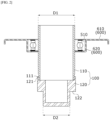
- FIG. 2 is a cross-sectional view illustrating the shaft, the first bearing, and the bearing housing
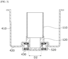
- FIG. 3 is a cross-sectional view illustrating the shaft, the second bearing, and the housing.
- the shaft 100 may include the first part 110 and the second part 120.
- the first part 110 and the second part 120 may have outer circumferential surfaces having different diameters D1 and D2.
- the diameter D2 of the outer circumferential surface of the second part 120 may be smaller than the diameter D1 of the outer circumferential surface of the first part 110.
- the second part 120 may include an upper region coupled to the first part 110 and a lower region disposed under the upper region.
- the second bearing 520 may be disposed outside the lower region. In this case, a diameter of an outer circumferential surface of the upper region may be different from a diameter of an outer circumferential surface of the lower region.
- the diameter of the outer circumferential surface of the upper region may be greater than the diameter of the outer circumferential surface of the lower region.
- the second part 120 may include an end step 122.
- the end step may be disposed on an inner ring of the second bearing 520 to support the second bearing 520.
- the upper region may be referred to as a first region of the second part 120
- the lower region may be referred to as a second region of the second part 120.
- the first part 110 may include a first end portion 111 coupled to the second part 120.
- the second part 120 may include a second end portion 121 coupled to the first end portion 111.
- the first end portion 111 and the second end portion 121 may overlap in the radial direction.
- the second end portion 121 may be disposed outside of the first end portion 111.
- a groove may be concavely formed in the shaft 100 in the radial direction.
- first part 110 and the second part 120 may overlap the rotor 200 in the radial direction.
- an upper portion of the rotor 200 may be disposed in contact with the first part 110, and a lower portion of the rotor 200 may be disposed in contact with the upper region of the second part 120.
- the first part 110 and the second part 120 may be separate parts. In this case, the first part 110 and the second part 120 may also be integrally formed with each other.
- the first bearing 510 may be disposed on the first part 110. In addition, the first bearing 510 may support the first part 110. In addition, the first bearing 510 may be supported by the bearing housing 600.
- the first bearing 510 may be disposed outside the first part 110.
- the first bearing 510 may be slidably disposed on the outer circumferential surface of the first part 110. That is, the first bearing 510 may be fastened to the shaft 100 through a sliding fit method.
- a diameter of an inner circumferential surface of the first bearing 510 may be greater than the diameter D1 of the first part 110.
- the bearing housing 600 may include a plate portion 610 and a first bearing pocket 620.
- the plate portion 610 may be spaced apart from the stator 300 in the axial direction.
- the plate portion 610 may be coupled to the housing 400.
- the plate portion 610 may have a circular hole formed to vertically pass therethrough.
- the first bearing pocket 620 may be disposed inside the plate portion 610.
- the first bearing 510 may be disposed in the first bearing pocket 620.
- the first bearing 510 may be fixedly installed in the first bearing pocket 620.
- An outer circumferential surface of the first bearing 510 may be the same as an inner circumferential surface of the first bearing pocket 620.
- the first bearing 510 may be press-fitted into the first bearing pocket 620.
- the second bearing 520 may be disposed on the second part 120.
- the second bearing 520 may be fixed to the outer circumferential surface of the second part 120. Accordingly, the shaft 100 may be press-fitted into the second bearing 520.
- a diameter D4 of an inner circumferential surface of the second bearing 520 may be the same as the diameter D2 of the second part 120.
- the diameter of the inner circumferential surface of the second bearing 520 may be smaller than the diameter of the inner circumferential surface of the first bearing 510.
- the housing 400 may include a body 410, a bottom surface 420, and a second bearing pocket 430.
- the body 410 may have a cylindrical shape.
- the stator 300 may be disposed inside the body 410.
- the body 410 may be coupled to the bearing housing 600.
- the bottom surface 420 may extend inward from the body 410.
- the bottom surface 420 may be spaced apart from the stator 300 in the axial direction.
- the second bearing pocket 430 may be disposed inside the bottom surface 420.
- the second bearing 520 may be disposed in the second bearing pocket 430.
- the second bearing 520 may be fixed to the second bearing pocket 430.
- An outer circumferential surface of the second bearing 520 may be the same as the inner circumferential surface of the second bearing pocket 430.
- the second bearing 520 may be press-fitted into the second bearing pocket 430.
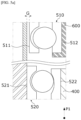
- FIG. 4 is a schematic view illustrating a structure in which the shaft, the first bearing, the second bearing, the housing, and the bearing housing are coupled.
- the first bearing 510 may be fastened to the shaft 100 through the sliding fit method.
- the first bearing 510 may include a first inner surface 511 and a first outer surface 512.
- the first inner surface 511 may be disposed to face the first part 110.
- a gap G may be formed between the first inner surface 511 and the first part 110.
- the first outer surface 512 may be disposed to face the bearing housing 600.
- the first outer surface 512 may be in contact with the bearing housing 600 without a gap.
- the first bearing 510 may be press-fitted into the bearing housing 600. In this case, the gap G may be called a gap.
- first bearing 510 and the shaft 100 are disposed with the gap interposed therebetween, and the first bearing 510 is fixed to the bearing housing 600, an axial position of the first bearing 510 may be fixed regardless of axial movement of the shaft 100.
- the second bearing 520 may be fastened to the shaft 100 and the housing 400 through a press-fitting method.
- the second bearing 520 may include a second inner surface 521 and a second outer surface 522.
- the second inner surface 521 may be an inner surface of the inner ring of the second bearing 520
- the second outer surface 522 may be an outer surface of an outer ring of the second bearing 520.
- the second inner surface 521 may be disposed to face the second part 120.
- the second inner surface 521 and the second part 120 may be in contact with each other without a gap. Accordingly, the second inner surface 521 may overlap the upper region of the second part 120 in the axial direction.
- the second outer surface 522 may be disposed to face the bearing housing 600. In this case, the second outer surface 522 may not overlap the upper region of the second part 120 in the axial direction.
- the second outer surface 522 is disposed to be spaced apart from the upper region of the second part 120 in the radial direction and may overlap the rotor 200 in the axial direction.
- the second outer surface 522 may be in contact with the bearing housing 600 without a gap.
- the second bearing 520 may be press-fitted into the housing 400.
- the second part 120 may be press-fitted into the second bearing 520.
- the second bearing 520 may be firmly fixed to the shaft 100 and the housing 400 to effectively prevent movement of the shaft 100.
- axial and radial movement of the shaft 100 can be reduced by firmly fixing a lower portion of the shaft 100 using the second bearing 520 which is a lower bearing.
- an upper portion of the shaft 100 may be fastened to the first bearing 510 which is an upper bearing through the sliding fit method to minimize movement of the upper bearing occurring due to movement of the shaft 100. Accordingly, axial and radial movement of the shaft 100 can be reduced, and the driving stability of the upper bearing can be secured against movement.
- FIGS. 5A and 5B are views for describing changes in position of the first bearing, the second bearing, the housing, and the bearing housing according to axial movement of the shaft.
- FIG. 5A is the view for describing changes in position of the first bearing, the second bearing, the housing, and the bearing housing according to movement of the shaft in a first direction
- FIG. 5B is the view for describing changes in position of the first bearing, the second bearing, the housing, and the bearing housing according to movement of the shaft in a second direction.
- a force may be applied in a first direction P1 by axial movement of the shaft 100.
- the first direction P1 is a direction from the housing 400 toward the bearing housing 600. That is, the force applied to the shaft 100 in the first direction P1 may be a force which pulls the shaft 100 from the housing 400.
- the second inner surface 521 may be moved along the shaft 100 in the first direction P1. Meanwhile, the second outer surface 522 may be fixed to the housing 400. In this case, the second bearing 520 can prevent axial movement of the shaft 100 using a fixing force between the second outer surface 522 and the housing 400.
- the first inner surface 511 and the first part 110 may be disposed with the gap G interposed therebetween.
- the first inner surface 511 may be separated from the shaft 100. Accordingly, a position of the first inner surface 511 may be maintained even when the shaft 100 moves in the first direction P1. An axial position of the first bearing 510 may be maintained regardless of movement of the shaft 100.
- a force may be applied in a second direction P2 due to axial movement of the shaft 100.
- the second direction P2 is a direction from the bearing housing 600 toward the housing 400. That is, the force applied to the shaft 100 in the second direction P2 may be a force which pushes the shaft 100 toward the housing 400.
- the second inner surface 521 may move along the shaft 100 in the second direction P2. However, as a second lower surface of the second bearing 520 is supported by the bearing pocket 430 of the housing 400, movement of the second inner surface 521 in the second direction P2 can be restricted.
- the second outer surface 522 may be fixed to the housing 400. The second bearing 520 may be firmly fixed to the housing 400 to prevent axial movement of the shaft 100.
- the first inner surface 511 may be separated from the first part 110 by the gap G. Accordingly, a position of the first inner surface 511 may be maintained even when the shaft 100 moves in the second direction P2. An axial position of the first bearing 510 may be maintained regardless of movement of the shaft 100.
- FIG. 6 is a perspective view illustrating the bearing housing
- FIG. 7 is a plan view illustrating the bearing housing.
- the bearing housing 600 may include the plate portion 610 and the first bearing pocket 620.
- the plate portion 610 may be coupled to the housing 400.
- the plate portion 610 may be spaced apart from the stator 300 in the axial direction.
- the first bearing pocket 620 may be disposed inside the plate portion 610.
- a diameter D3 of the first bearing pocket 620 may be the same as a diameter of the first bearing.
- the first bearing 510 may be press-fitted into the first bearing pocket 620.
- the first bearing pocket 620 may be open to face an opposite side of the rotor 200.
- the first bearing 510 may be disposed in the first bearing pocket 620.
- a hole 620H through which the shaft 100 passes may be formed in the first bearing pocket 620.
- the diameter D4 of the hole 620H may be smaller than the diameter D3 of the first bearing pocket 620 and greater than a diameter of the shaft 100.
- the first bearing pocket 620 may include a first portion 621 and a second portion 622.
- the first portion 621 may extend from the plate portion 610 toward the rotor 200.
- the first portion 621 may be in contact with the first outer surface 512 of the first bearing 510.
- the first portion 621 may overlap the first bearing 510 in the radial direction.
- the second portion 622 may extend inward from the first portion 621.
- the second portion 622 may support a first lower surface of the first bearing 510.
- the second portion 622 may support the first bearing 510 in the axial direction.
- the second portion 622 may support a lower portion of an outer ring of the first bearing 510 in the axial direction.
- the second portion 622 may be disposed between the first bearing 510 and the rotor 200.
- the second portion 622 may include the hole 620H.
- the first bearing pocket 620 is formed to be open toward the opposite side of the rotor 200, a first upper surface disposed at an opposite side of the first lower surface is not in contact with the first bearing pocket 620.
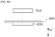
- FIGS. 8A to 8C are perspective views for describing an assembly process of the motor according to the embodiment.
- FIG. 8A is the view illustrating the shaft, the housing, and an assembly process of the shaft when the motor is assembled according to the embodiment
- FIG. 8B is a view illustrating an assembly process of the first bearing and the bearing housing when the motor is assembled according to the embodiment
- FIG. 8C is a view illustrating an assembly process of the housing and the bearing housing when the motor is assembled according to the embodiment.
- the second bearing 520 and the shaft 100 may be sequentially press-fitted into the housing 400.
- the second bearing 520 may be press-fitted into the housing 400 in the second direction P2.
- the shaft 100 may be press-fitted into the second bearing 520. Accordingly, the second bearing 520 and the shaft 100 may be fixed to the housing 400.
- the first bearing 510 may be press-fitted into the bearing housing 600.
- the first bearing 510 may be press-fitted into the bearing pocket 620 in the second direction P2. Accordingly, the first bearing 510 may be fixed to the bearing housing 600.
- the bearing housing 600 to which the first bearing 510 is fixed may be coupled to the housing 400.
- the first bearing 510 may be coupled to the shaft 100 through the sliding fit method.
- the lower portion of the shaft 100 can be fixed to prevent axial and radial movement of the shaft 100, and the upper portion of the shaft 100 can be fastened to the upper bearing through the sliding fit method to minimize movement of the upper bearing occurring due to the movement of the shaft 100.
- Table 1 shows separation distances between first and second bearings and a bearing housing, a shaft, and a housing of a motor according to each of the comparative examples and the examples.
- Table 2 is a result of measuring a moving distance of the shaft when a force is applied to the shaft of the motor in the axial direction according to each of the comparative examples and the examples.
- a first bearing is press-fitted into and coupled to the shaft, and a second bearing is slid in and coupled to the shaft.
- the first bearing is coupled to the shaft through the sliding fit method, and the second bearing is press-fitted into and coupled to the shaft.
- a force of 200 N was applied to the shaft in the first direction P1
- a force of 7000 N was applied to the shaft in the second direction P2.
- the force in the first direction P1 is a force which pulls the shaft from the housing
- the force in the second direction P2 is a force which pushes the shaft toward the housing.
- Example 1 although the same force in the same direction was applied as in Comparative example 1, it can be seen that a moving distance in the axial direction is decreased from 500 ⁇ m to 10 ⁇ m and a moving distance in the radial direction is decreased from 55 ⁇ m to 25 ⁇ m.
- Example 2 although the same force in the same direction was applied as in Comparative example 2, it can be seen that a moving distance in the axial direction is decreased from 500 ⁇ m to 10 ⁇ m and a moving distance in the radial direction is decreased from 55 ⁇ m to 25 ⁇ m.
- movement of the shaft can be decreased in any case in which a pulling or pushing force is applied to the shaft.
- an example of an inner rotor type motor has been described, but the present invention is not limited thereto.
- the present invention can also be applied to an outer rotor type motor.
- the present invention can be used in various devices such as vehicles or home appliances.
Landscapes
- Engineering & Computer Science (AREA)
- General Engineering & Computer Science (AREA)
- Power Engineering (AREA)
- Mechanical Engineering (AREA)
- Motor Or Generator Frames (AREA)
- Mounting Of Bearings Or Others (AREA)
- Connection Of Motors, Electrical Generators, Mechanical Devices, And The Like (AREA)
Abstract
Description
- The present invention relates to a motor.
- A motor includes a rotor and a stator. In this case, the rotor rotates due to an electrical interaction between the rotor and the stator. In addition, the motor includes a bearing which supports the shaft.
- The bearing may be moved in conjunction with axial movement of the shaft which is driven at a high speed. Accordingly, a supporting force of the bearing may be reduced, and the driving stability of the motor can be reduced.
- Accordingly, the present invention is directed to providing a motor in which the driving stability of a bearing is secured against movement of a shaft.
- Objectives to be solved by embodiments are not limited to the objectives described above, and objectives which are not described above will be clearly understood by those skilled in the art from the following descriptions.
- One aspect of the present invention provides a motor including a shaft, a rotor coupled to the shaft, a stator disposed to correspond to the rotor, a housing configured to accommodate the stator, a first bearing which supports the shaft, and a bearing housing which supports the first bearing, wherein the first bearing includes a first inner surface disposed to face the shaft and a first outer surface disposed to face an opposite side of the first inner surface, the first inner surface is disposed to be slidable on the shaft, and the first outer surface is fixed to the housing.
- According to an embodiment, a lower portion of a shaft can be fixed to prevent axial and radial movement of the shaft, and the shaft can be fastened to an upper bearing through a sliding fit method to minimize movement of the upper bearing due to movement of the shaft.
- Accordingly, the axial and radial movement of the shaft can be reduced, and the driving stability of the upper bearing can be secured against the movement.
- In addition, a washer and grease can be omitted to reduce a cost, and a problem of assembly failure can be solved.
- Various useful advantages and effects of the embodiments are not limited to the above-described contents and will be more easily understood from descriptions of the specific embodiments.
-
-
FIG. 1 is a cross-sectional view illustrating a motor according to an embodiment. -
FIG. 2 is a cross-sectional view illustrating a shaft, a first bearing, and a bearing housing. -
FIG. 3 is a cross-sectional view illustrating the shaft, a second bearing, and a housing. -
FIG. 4 is a schematic view illustrating a structure in which the shaft, the first bearing, the second bearing, the housing, and the bearing housing are coupled. -
FIGS. 5A and5B are views for describing changes in position of the first bearing, the second bearing, the housing, and the bearing housing according to axial movement of the shaft. -
FIG. 6 is a perspective view illustrating the bearing housing. -
FIG. 7 is a plan view illustrating the bearing housing. -
FIGS. 8A to 8C are perspective views for describing an assembly process of the motor according to the embodiment. - Hereafter, an exemplary embodiment of the present invention will be described in detail with reference to the accompanying drawings.
- A direction parallel to a longitudinal direction (vertical direction) of a shaft is referred to as an axial direction, a direction perpendicular to the axial direction based on the shaft is referred to as a radial direction, and a direction along a circle having a radius in the radial direction based on the shaft is referred to as a circumferential direction.
-
FIG. 1 is a cross-sectional view illustrating a motor according to an embodiment. InFIG. 1 , an X direction may be a radial direction, and a Y direction may an axial direction. In addition, a reference symbol "C" illustrated inFIG. 1 may be a rotary center of theshaft 100. - Referring to
FIG. 1 , the motor may include theshaft 100, arotor 200, astator 300, ahousing 400,bearings 500, and abearing housing 600. - Hereafter, the term "inward" is a direction from the
housing 400 toward theshaft 100 which is a center C of the motor, and the term "outward" is a direction opposite to "inward," that is, the direction from theshaft 100 toward thehousing 400. - The
shaft 100 may be a hollow member of which one side is open. Theshaft 100 may be disposed so that parts having different outer diameters are divided in the axial direction. Theshaft 100 may include afirst part 110 and asecond part 120. Thefirst part 110 and thesecond part 120 may be disposed in the axial direction. Meanwhile, theshaft 100 may be a single member. - The
shaft 100 may be coupled to therotor 200. When a current is supplied, an electromagnetic interaction occurs between therotor 200 and thestator 300, therotor 200 rotates, and theshaft 100 rotates in conjunction with therotor 200. Theshaft 100 may be connected to a steering system of a vehicle and transmit power to the steering system. - The
rotor 200 rotates due to an electrical interaction between therotor 200 and thestator 300. Therotor 200 may be disposed inside thestator 300. Therotor 200 may include a rotor core and a rotor magnet disposed on the rotor core. - The
stator 300 is disposed outside therotor 200. Thestator 300 may include astator core 310, acoil 320, and aninsulator 330 mounted on thestator core 310. Thecoil 320 may be wound around theinsulator 330. Theinsulator 330 is disposed between thecoil 320 and thestator core 310. The coil induces an electrical interaction with the rotor magnet. - The
housing 400 may be disposed outside thestator 300. Thehousing 400 may be a cylindrical member of which one side is open. A shape or a material of thehousing 400 may variously vary, and a metal material which can endure well even at high temperatures may be selected. - Each of the
bearings 500 may support theshaft 100. Thebearings 500 may include a first bearing 510 and a second bearing 520. The first bearing 510 and the second bearing 520 may be disposed to be spaced apart from each other in the axial direction. In this case, the first bearing 510 may be disposed in thebearing housing 600. In addition, the second bearing 520 may be disposed in thehousing 400. - The bearing
housing 600 may support the bearing 500. In addition, the bearinghousing 600 may be coupled to thehousing 400. In addition, a hole through which theshaft 100 passes may be formed in thebearing housing 600. -
FIG. 2 is a cross-sectional view illustrating the shaft, the first bearing, and the bearing housing, andFIG. 3 is a cross-sectional view illustrating the shaft, the second bearing, and the housing. - Referring to
FIG. 2 , theshaft 100 may include thefirst part 110 and thesecond part 120. Thefirst part 110 and thesecond part 120 may have outer circumferential surfaces having different diameters D1 and D2. The diameter D2 of the outer circumferential surface of thesecond part 120 may be smaller than the diameter D1 of the outer circumferential surface of thefirst part 110. Thesecond part 120 may include an upper region coupled to thefirst part 110 and a lower region disposed under the upper region. In addition, thesecond bearing 520 may be disposed outside the lower region. In this case, a diameter of an outer circumferential surface of the upper region may be different from a diameter of an outer circumferential surface of the lower region. Specifically, the diameter of the outer circumferential surface of the upper region may be greater than the diameter of the outer circumferential surface of the lower region. Accordingly, thesecond part 120 may include anend step 122. In addition, the end step may be disposed on an inner ring of thesecond bearing 520 to support thesecond bearing 520. In this case, the upper region may be referred to as a first region of thesecond part 120, and the lower region may be referred to as a second region of thesecond part 120. - The
first part 110 may include afirst end portion 111 coupled to thesecond part 120. In addition, thesecond part 120 may include asecond end portion 121 coupled to thefirst end portion 111. In this case, thefirst end portion 111 and thesecond end portion 121 may overlap in the radial direction. As illustrated inFIG. 2 , thesecond end portion 121 may be disposed outside of thefirst end portion 111. In addition, when thefirst end portion 111 and thesecond end portion 121 are coupled, a groove may be concavely formed in theshaft 100 in the radial direction. - In addition, the
first part 110 and thesecond part 120 may overlap therotor 200 in the radial direction. Specifically, an upper portion of therotor 200 may be disposed in contact with thefirst part 110, and a lower portion of therotor 200 may be disposed in contact with the upper region of thesecond part 120. - The
first part 110 and thesecond part 120 may be separate parts. In this case, thefirst part 110 and thesecond part 120 may also be integrally formed with each other. - The
first bearing 510 may be disposed on thefirst part 110. In addition, thefirst bearing 510 may support thefirst part 110. In addition, thefirst bearing 510 may be supported by the bearinghousing 600. - The
first bearing 510 may be disposed outside thefirst part 110. Thefirst bearing 510 may be slidably disposed on the outer circumferential surface of thefirst part 110. That is, thefirst bearing 510 may be fastened to theshaft 100 through a sliding fit method. In this case, a diameter of an inner circumferential surface of thefirst bearing 510 may be greater than the diameter D1 of thefirst part 110. - The bearing
housing 600 may include aplate portion 610 and afirst bearing pocket 620. - The
plate portion 610 may be spaced apart from thestator 300 in the axial direction. Theplate portion 610 may be coupled to thehousing 400. In addition, theplate portion 610 may have a circular hole formed to vertically pass therethrough. - The
first bearing pocket 620 may be disposed inside theplate portion 610. - The
first bearing 510 may be disposed in thefirst bearing pocket 620. Thefirst bearing 510 may be fixedly installed in thefirst bearing pocket 620. An outer circumferential surface of thefirst bearing 510 may be the same as an inner circumferential surface of thefirst bearing pocket 620. Thefirst bearing 510 may be press-fitted into thefirst bearing pocket 620. - Referring to
FIG. 3 , thesecond bearing 520 may be disposed on thesecond part 120. - The
second bearing 520 may be fixed to the outer circumferential surface of thesecond part 120. Accordingly, theshaft 100 may be press-fitted into thesecond bearing 520. In this case, a diameter D4 of an inner circumferential surface of thesecond bearing 520 may be the same as the diameter D2 of thesecond part 120. The diameter of the inner circumferential surface of thesecond bearing 520 may be smaller than the diameter of the inner circumferential surface of thefirst bearing 510. - The
housing 400 may include abody 410, abottom surface 420, and asecond bearing pocket 430. - The
body 410 may have a cylindrical shape. Thestator 300 may be disposed inside thebody 410. Thebody 410 may be coupled to the bearinghousing 600. Thebottom surface 420 may extend inward from thebody 410. Thebottom surface 420 may be spaced apart from thestator 300 in the axial direction. In addition, thesecond bearing pocket 430 may be disposed inside thebottom surface 420. Thesecond bearing 520 may be disposed in thesecond bearing pocket 430. - The
second bearing 520 may be fixed to thesecond bearing pocket 430. An outer circumferential surface of thesecond bearing 520 may be the same as the inner circumferential surface of thesecond bearing pocket 430. Thesecond bearing 520 may be press-fitted into thesecond bearing pocket 430. -
FIG. 4 is a schematic view illustrating a structure in which the shaft, the first bearing, the second bearing, the housing, and the bearing housing are coupled. - Referring to
FIG. 4 , thefirst bearing 510 may be fastened to theshaft 100 through the sliding fit method. - The
first bearing 510 may include a firstinner surface 511 and a firstouter surface 512. The firstinner surface 511 may be disposed to face thefirst part 110. In this case, a gap G may be formed between the firstinner surface 511 and thefirst part 110. In addition, the firstouter surface 512 may be disposed to face the bearinghousing 600. The firstouter surface 512 may be in contact with the bearinghousing 600 without a gap. Thefirst bearing 510 may be press-fitted into the bearinghousing 600. In this case, the gap G may be called a gap. - Since the
first bearing 510 and theshaft 100 are disposed with the gap interposed therebetween, and thefirst bearing 510 is fixed to the bearinghousing 600, an axial position of thefirst bearing 510 may be fixed regardless of axial movement of theshaft 100. - The
second bearing 520 may be fastened to theshaft 100 and thehousing 400 through a press-fitting method. - The
second bearing 520 may include a secondinner surface 521 and a secondouter surface 522. In this case, the secondinner surface 521 may be an inner surface of the inner ring of thesecond bearing 520, and the secondouter surface 522 may be an outer surface of an outer ring of thesecond bearing 520. The secondinner surface 521 may be disposed to face thesecond part 120. The secondinner surface 521 and thesecond part 120 may be in contact with each other without a gap. Accordingly, the secondinner surface 521 may overlap the upper region of thesecond part 120 in the axial direction. In addition, the secondouter surface 522 may be disposed to face the bearinghousing 600. In this case, the secondouter surface 522 may not overlap the upper region of thesecond part 120 in the axial direction. That is, the secondouter surface 522 is disposed to be spaced apart from the upper region of thesecond part 120 in the radial direction and may overlap therotor 200 in the axial direction. The secondouter surface 522 may be in contact with the bearinghousing 600 without a gap. Thesecond bearing 520 may be press-fitted into thehousing 400. In addition, thesecond part 120 may be press-fitted into thesecond bearing 520. - The
second bearing 520 may be firmly fixed to theshaft 100 and thehousing 400 to effectively prevent movement of theshaft 100. - In the motor according to the embodiment, axial and radial movement of the
shaft 100 can be reduced by firmly fixing a lower portion of theshaft 100 using thesecond bearing 520 which is a lower bearing. In addition, an upper portion of theshaft 100 may be fastened to thefirst bearing 510 which is an upper bearing through the sliding fit method to minimize movement of the upper bearing occurring due to movement of theshaft 100. Accordingly, axial and radial movement of theshaft 100 can be reduced, and the driving stability of the upper bearing can be secured against movement. -
FIGS. 5A and5B are views for describing changes in position of the first bearing, the second bearing, the housing, and the bearing housing according to axial movement of the shaft. In this case,FIG. 5A is the view for describing changes in position of the first bearing, the second bearing, the housing, and the bearing housing according to movement of the shaft in a first direction, andFIG. 5B is the view for describing changes in position of the first bearing, the second bearing, the housing, and the bearing housing according to movement of the shaft in a second direction. - Referring to
FIG. 5A , a force may be applied in a first direction P1 by axial movement of theshaft 100. The first direction P1 is a direction from thehousing 400 toward the bearinghousing 600. That is, the force applied to theshaft 100 in the first direction P1 may be a force which pulls theshaft 100 from thehousing 400. - The second
inner surface 521 may be moved along theshaft 100 in the first direction P1. Meanwhile, the secondouter surface 522 may be fixed to thehousing 400. In this case, thesecond bearing 520 can prevent axial movement of theshaft 100 using a fixing force between the secondouter surface 522 and thehousing 400. - The first
inner surface 511 and thefirst part 110 may be disposed with the gap G interposed therebetween. The firstinner surface 511 may be separated from theshaft 100. Accordingly, a position of the firstinner surface 511 may be maintained even when theshaft 100 moves in the first direction P1. An axial position of thefirst bearing 510 may be maintained regardless of movement of theshaft 100. - Referring to
FIG. 5B , a force may be applied in a second direction P2 due to axial movement of theshaft 100. The second direction P2 is a direction from the bearinghousing 600 toward thehousing 400. That is, the force applied to theshaft 100 in the second direction P2 may be a force which pushes theshaft 100 toward thehousing 400. - The second
inner surface 521 may move along theshaft 100 in the second direction P2. However, as a second lower surface of thesecond bearing 520 is supported by the bearingpocket 430 of thehousing 400, movement of the secondinner surface 521 in the second direction P2 can be restricted. In addition, the secondouter surface 522 may be fixed to thehousing 400. Thesecond bearing 520 may be firmly fixed to thehousing 400 to prevent axial movement of theshaft 100. - Meanwhile, the first
inner surface 511 may be separated from thefirst part 110 by the gap G. Accordingly, a position of the firstinner surface 511 may be maintained even when theshaft 100 moves in the second direction P2. An axial position of thefirst bearing 510 may be maintained regardless of movement of theshaft 100. -
FIG. 6 is a perspective view illustrating the bearing housing, andFIG. 7 is a plan view illustrating the bearing housing. - Referring to
FIGS. 6 and7 , the bearinghousing 600 may include theplate portion 610 and thefirst bearing pocket 620. - The
plate portion 610 may be coupled to thehousing 400. Theplate portion 610 may be spaced apart from thestator 300 in the axial direction. Thefirst bearing pocket 620 may be disposed inside theplate portion 610. - A diameter D3 of the
first bearing pocket 620 may be the same as a diameter of the first bearing. Thefirst bearing 510 may be press-fitted into thefirst bearing pocket 620. Thefirst bearing pocket 620 may be open to face an opposite side of therotor 200. Thefirst bearing 510 may be disposed in thefirst bearing pocket 620. Ahole 620H through which theshaft 100 passes may be formed in thefirst bearing pocket 620. In this case, the diameter D4 of thehole 620H may be smaller than the diameter D3 of thefirst bearing pocket 620 and greater than a diameter of theshaft 100. - The
first bearing pocket 620 may include afirst portion 621 and asecond portion 622. - The
first portion 621 may extend from theplate portion 610 toward therotor 200. Thefirst portion 621 may be in contact with the firstouter surface 512 of thefirst bearing 510. Thefirst portion 621 may overlap thefirst bearing 510 in the radial direction. - The
second portion 622 may extend inward from thefirst portion 621. Thesecond portion 622 may support a first lower surface of thefirst bearing 510. Thesecond portion 622 may support thefirst bearing 510 in the axial direction. As illustrated inFIG. 4 , thesecond portion 622 may support a lower portion of an outer ring of thefirst bearing 510 in the axial direction. Thesecond portion 622 may be disposed between thefirst bearing 510 and therotor 200. Thesecond portion 622 may include thehole 620H. In addition, since thefirst bearing pocket 620 is formed to be open toward the opposite side of therotor 200, a first upper surface disposed at an opposite side of the first lower surface is not in contact with thefirst bearing pocket 620. -
FIGS. 8A to 8C are perspective views for describing an assembly process of the motor according to the embodiment.FIG. 8A is the view illustrating the shaft, the housing, and an assembly process of the shaft when the motor is assembled according to the embodiment,FIG. 8B is a view illustrating an assembly process of the first bearing and the bearing housing when the motor is assembled according to the embodiment, andFIG. 8C is a view illustrating an assembly process of the housing and the bearing housing when the motor is assembled according to the embodiment. - Referring to
FIG. 8A , thesecond bearing 520 and theshaft 100 may be sequentially press-fitted into thehousing 400. First, thesecond bearing 520 may be press-fitted into thehousing 400 in the second direction P2. In addition, theshaft 100 may be press-fitted into thesecond bearing 520. Accordingly, thesecond bearing 520 and theshaft 100 may be fixed to thehousing 400. - Meanwhile, as illustrated in
FIG. 8B , thefirst bearing 510 may be press-fitted into the bearinghousing 600. In this case, thefirst bearing 510 may be press-fitted into thebearing pocket 620 in the second direction P2. Accordingly, thefirst bearing 510 may be fixed to the bearinghousing 600. - As illustrated in
FIG. 8C , the bearinghousing 600 to which thefirst bearing 510 is fixed may be coupled to thehousing 400. In this case, thefirst bearing 510 may be coupled to theshaft 100 through the sliding fit method. - In the motor according to the present invention, the lower portion of the
shaft 100 can be fixed to prevent axial and radial movement of theshaft 100, and the upper portion of theshaft 100 can be fastened to the upper bearing through the sliding fit method to minimize movement of the upper bearing occurring due to the movement of theshaft 100. - Hereinafter, a moving distance of a
shaft 100 of a motor according to each of comparative examples and examples was measured to more specifically describe effects of the present invention. - Table 1 shows separation distances between first and second bearings and a bearing housing, a shaft, and a housing of a motor according to each of the comparative examples and the examples. In addition, Table 2 is a result of measuring a moving distance of the shaft when a force is applied to the shaft of the motor in the axial direction according to each of the comparative examples and the examples.
- In Comparative example 1 and Comparative example 2, a first bearing is press-fitted into and coupled to the shaft, and a second bearing is slid in and coupled to the shaft. In addition, in the examples, the first bearing is coupled to the shaft through the sliding fit method, and the second bearing is press-fitted into and coupled to the shaft.
- In addition, in Comparative example 1 and Example 1, a force of 200 N was applied to the shaft in the first direction P1, and in Comparative example 2 and Example 2, a force of 7000 N was applied to the shaft in the second direction P2. In this case, the force in the first direction P1 is a force which pulls the shaft from the housing, and the force in the second direction P2 is a force which pushes the shaft toward the housing.
[Table 1] Separation distance (µm) between First bearing and Housing Separation distance (µm) between First bearing and Shaft Separation distance (µm) between Second bearing and Housing Separation distance (µm) between Second bearing and Shaft Comparative Example 1 30 0 0 25 Comparative Example 2 30 0 0 25 Example 1 0 25 0 0 Example 2 0 25 0 0 [Table 2] Force (N) in P1 Direction Force (N) in P2 Direction Force (N) applied to First bearing Force (N) applied to Second bearing Moving distance (µm) in axial direction Moving distance (µm) in radial direction Comparative Example 1 - 7000 0 7200 500 55 Comparative Example 2 200 - -200 0 500 55 Example 1 - 7000 0 7000 10 25 Example 2 200 - 0 -200 10 25 - Referring to Tables 1 and 2, in Example 1, although the same force in the same direction was applied as in Comparative example 1, it can be seen that a moving distance in the axial direction is decreased from 500 µm to 10 µm and a moving distance in the radial direction is decreased from 55 µm to 25 µm. In addition, in Example 2, although the same force in the same direction was applied as in Comparative example 2, it can be seen that a moving distance in the axial direction is decreased from 500 µm to 10 µm and a moving distance in the radial direction is decreased from 55 µm to 25 µm. As described above, in the examples, movement of the shaft can be decreased in any case in which a pulling or pushing force is applied to the shaft.
- In the above embodiments, an example of an inner rotor type motor has been described, but the present invention is not limited thereto. The present invention can also be applied to an outer rotor type motor. In addition, the present invention can be used in various devices such as vehicles or home appliances.
- While the present invention has been described above with reference to exemplary embodiments, it may be understood by those skilled in the art that various modifications and changes of the present invention may be made within a range not departing from the spirit and scope of the present invention defined by the appended claims.
-
- 100: SHAFT
- 200: ROTOR
- 300: STATOR
- 400: HOUSING
- 500: BEARING
- 600: BEARING HOUSING
Claims (17)
- A motor comprising:a shaft;a rotor coupled to the shaft;a stator disposed to correspond to the rotor;a housing configured to accommodate the stator;a bearing housing coupled to an upper portion of the housing; anda first bearing coupled to the bearing housing,wherein the first bearing includes a first inner surface disposed to face the shaft and a first outer surface disposed to face an opposite side of the first inner surface,the first inner surface is disposed to be slidable on the shaft, andthe first outer surface is fixed to the bearing housing.
- The motor of claim 1, wherein a gap is formed between the first inner surface and an outer circumferential surface of the shaft.
- The motor of claim 1, wherein:the first bearing includes a first lower surface disposed to face the rotor; andthe bearing housing is in contact with the first outer surface and the first lower surface.
- The motor of claim 3, wherein:the bearing housing includes a first bearing pocket in which the first bearing is disposed; andthe first bearing pocket includes a first portion in contact with the first outer surface and a second portion in contact with the first lower surface.
- The motor of claim 4, wherein:the first bearing includes a first upper surface disposed to face an opposite side of the first lower surface; andthe first upper surface is not in contact with the first bearing pocket.
- The motor of claim 4, wherein:the second portion includes a hole through which the shaft passes; anda diameter of the hole is smaller than a diameter of the first bearing and greater than a diameter of the shaft.
- The motor of claim 1, comprising a second bearing configured to support the shaft,
wherein the second bearing is disposed in the housing. - The motor of claim 7, wherein the second bearing includes:a second inner surface disposed to face the shaft; anda second outer surface disposed to face an opposite side of the second inner surface,wherein the second inner surface is fixed to the shaft, andthe second outer surface is fixed to the housing.
- The motor of claim 8, wherein:the shaft includes a first part and a second part which are disposed in an axial direction; anda diameter of the first part is greater than a diameter of the second part.
- The motor of claim 9, wherein:the first bearing is disposed in a radial direction of the first part; andthe second bearing is disposed in a radial direction of the second part.
- A motor comprising:a shaft;a rotor coupled to the shaft;a stator disposed to correspond to the rotor;a housing configured to accommodate the stator;a bearing housing coupled to an upper portion of the housing;a first bearing coupled to the bearing housing; anda second bearing coupled to the housing,wherein the first bearing and an outer circumferential surface of the shaft are disposed with a predetermined gap interposed therebetween, andthe second bearing is in contact with the outer circumferential surface of the shaft.
- The motor of claim 11, wherein:the shaft includes a first part and a second part which are disposed in an axial direction;the first bearing is disposed in a radial direction of the first part;the second bearing is disposed in a radial direction of the second part; anda diameter of the first part is different from a diameter of the second part.
- The motor of claim 12, wherein the second part includes:an upper region coupled to the first part; anda lower region disposed under the upper region,wherein a diameter of an outer circumferential surface of the upper region is greater than a diameter of an inner circumferential surface of the lower region so that an end step is formed on the second part, andthe second bearing is disposed outside the lower region.
- The motor of claim 13, wherein the end step supports an inner ring of the second bearing.
- The motor of claim 13, wherein:an upper portion of the rotor is in contact with the first part; anda lower portion of the rotor is in contact with the upper portion.
- The motor of claim 12, wherein:the second bearing includes a second inner surface disposed to face the shaft; anda second outer surface disposed at an opposite side of the inner surface,wherein the second inner surface overlaps the second part in the axial direction; andthe second outer surface overlaps the rotor in the axial direction.
- The motor of claim 12, wherein:the first part includes a first end portion;the second part includes a second end portion; andthe first end portion and the second end portion overlap in the radial direction.
Applications Claiming Priority (2)
| Application Number | Priority Date | Filing Date | Title |
|---|---|---|---|
| KR1020210021013A KR20220117542A (en) | 2021-02-17 | 2021-02-17 | Motor |
| PCT/KR2022/002325 WO2022177309A1 (en) | 2021-02-17 | 2022-02-17 | Motor |
Publications (2)
| Publication Number | Publication Date |
|---|---|
| EP4297250A1 true EP4297250A1 (en) | 2023-12-27 |
| EP4297250A4 EP4297250A4 (en) | 2025-01-15 |
Family
ID=82930935
Family Applications (1)
| Application Number | Title | Priority Date | Filing Date |
|---|---|---|---|
| EP22756507.4A Pending EP4297250A4 (en) | 2021-02-17 | 2022-02-17 | ENGINE |
Country Status (6)
| Country | Link |
|---|---|
| US (1) | US12445009B2 (en) |
| EP (1) | EP4297250A4 (en) |
| JP (1) | JP2024506129A (en) |
| KR (1) | KR20220117542A (en) |
| CN (1) | CN116848763A (en) |
| WO (1) | WO2022177309A1 (en) |
Family Cites Families (18)
| Publication number | Priority date | Publication date | Assignee | Title |
|---|---|---|---|---|
| US1326892A (en) * | 1919-12-30 | A cobpobation of con | ||
| JP4695309B2 (en) * | 2001-09-14 | 2011-06-08 | シチズンマイクロ株式会社 | motor |
| CN100499316C (en) * | 2003-04-14 | 2009-06-10 | 哈格雷夫斯技术公司 | Pump motor with bearing preload |
| JP5576708B2 (en) * | 2010-05-13 | 2014-08-20 | 東京パーツ工業株式会社 | Small motors and motor actuators |
| DE102012221596A1 (en) | 2012-11-26 | 2014-05-28 | Robert Bosch Gmbh | Stator with an encapsulation and electric machine with the stator |
| KR102116478B1 (en) * | 2013-11-19 | 2020-05-28 | 엘지이노텍 주식회사 | Motor |
| JP6618923B2 (en) * | 2014-04-04 | 2019-12-11 | エルジー イノテック カンパニー リミテッド | motor |
| KR102135647B1 (en) | 2015-02-10 | 2020-07-21 | 한온시스템 주식회사 | Air blower for fuel cell vehicle |
| EA030874B1 (en) * | 2015-05-08 | 2018-10-31 | Акционерное общество "Диаконт" | Linear electromechanical actuator |
| US9882447B2 (en) * | 2015-06-09 | 2018-01-30 | Regal Beloit America, Inc. | Electric machine, assembly and associated method |
| JP6243379B2 (en) | 2015-07-07 | 2017-12-06 | ミネベアミツミ株式会社 | motor |
| KR20170079425A (en) * | 2015-12-30 | 2017-07-10 | 주식회사 에스 씨디 | Brushless direct current motor |
| US11190077B2 (en) | 2017-01-11 | 2021-11-30 | Lg Innotek Co., Ltd. | Motor |
| KR20190093354A (en) * | 2018-02-01 | 2019-08-09 | 엘지이노텍 주식회사 | Motor |
| KR102396910B1 (en) * | 2018-04-26 | 2022-05-13 | 엘지전자 주식회사 | A Fan Motor |
| KR102094085B1 (en) * | 2018-11-09 | 2020-03-26 | (주)타마스 | Hollow Shaft Motor |
| KR101969789B1 (en) * | 2018-12-13 | 2019-04-17 | (주)계양정밀 | Electric turbocharger with oilless bearing |
| KR102123180B1 (en) * | 2019-02-01 | 2020-06-16 | (주)타마스 | Motor with Novel Hollow Shaft |
-
2021
- 2021-02-17 KR KR1020210021013A patent/KR20220117542A/en active Pending
-
2022
- 2022-02-17 CN CN202280014588.9A patent/CN116848763A/en active Pending
- 2022-02-17 JP JP2023540700A patent/JP2024506129A/en active Pending
- 2022-02-17 WO PCT/KR2022/002325 patent/WO2022177309A1/en not_active Ceased
- 2022-02-17 US US18/268,765 patent/US12445009B2/en active Active
- 2022-02-17 EP EP22756507.4A patent/EP4297250A4/en active Pending
Also Published As
| Publication number | Publication date |
|---|---|
| JP2024506129A (en) | 2024-02-09 |
| EP4297250A4 (en) | 2025-01-15 |
| US20240048019A1 (en) | 2024-02-08 |
| WO2022177309A1 (en) | 2022-08-25 |
| US12445009B2 (en) | 2025-10-14 |
| KR20220117542A (en) | 2022-08-24 |
| CN116848763A (en) | 2023-10-03 |
Similar Documents
| Publication | Publication Date | Title |
|---|---|---|
| EP1617094B1 (en) | Small-sized motor and method of manufacturing the same | |
| US5751085A (en) | Axial gap type electric motor with dynamic pressure air bearing | |
| US7975365B2 (en) | Method of making a stepping motor | |
| US20150275962A1 (en) | Motor | |
| US20080054747A1 (en) | Electrical machine having a rotor bearing integrated in the stator | |
| US10218243B2 (en) | Motor structure for electrolytic corrosion protection of bearing | |
| CN105449909B (en) | Axial flux motor bearing mounting system and method | |
| US20080247689A1 (en) | Motor | |
| CN204179803U (en) | Inner-rotor type motor | |
| US11984788B2 (en) | Electric motor | |
| US20200153310A1 (en) | Vehicle electric motor | |
| EP4297250A1 (en) | Motor | |
| US20240195261A1 (en) | Motor | |
| US12580442B2 (en) | Motor | |
| US12512718B2 (en) | Motor | |
| US10320264B2 (en) | Brushless motor | |
| KR102938743B1 (en) | Motor | |
| KR20220082317A (en) | Motor | |
| US10312771B2 (en) | Brushless motor | |
| US9135945B2 (en) | Disk rotating motor comprising bracket including cylindrical portion and folded portion | |
| US11843286B2 (en) | Motor | |
| JP2025017088A (en) | Current carrying unit and motor | |
| JP2019068523A (en) | motor | |
| JP2026063594A (en) | Sleeves, sleeves with bearings, and rotating equipment | |
| KR20230038873A (en) | Motor |
Legal Events
| Date | Code | Title | Description |
|---|---|---|---|
| STAA | Information on the status of an ep patent application or granted ep patent |
Free format text: STATUS: THE INTERNATIONAL PUBLICATION HAS BEEN MADE |
|
| PUAI | Public reference made under article 153(3) epc to a published international application that has entered the european phase |
Free format text: ORIGINAL CODE: 0009012 |
|
| STAA | Information on the status of an ep patent application or granted ep patent |
Free format text: STATUS: REQUEST FOR EXAMINATION WAS MADE |
|
| 17P | Request for examination filed |
Effective date: 20230628 |
|
| AK | Designated contracting states |
Kind code of ref document: A1 Designated state(s): AL AT BE BG CH CY CZ DE DK EE ES FI FR GB GR HR HU IE IS IT LI LT LU LV MC MK MT NL NO PL PT RO RS SE SI SK SM TR |
|
| DAV | Request for validation of the european patent (deleted) | ||
| DAX | Request for extension of the european patent (deleted) | ||
| A4 | Supplementary search report drawn up and despatched |
Effective date: 20241218 |
|
| RIC1 | Information provided on ipc code assigned before grant |
Ipc: H02K 5/15 20060101ALI20241212BHEP Ipc: H02K 7/00 20060101ALI20241212BHEP Ipc: H02K 7/08 20060101ALI20241212BHEP Ipc: H02K 1/27 20220101ALI20241212BHEP Ipc: H02K 1/12 20060101ALI20241212BHEP Ipc: H02K 5/173 20060101AFI20241212BHEP |