EP4297218A1 - Low-capacitive-reactance protection method and system, and computer-readable storage medium and computer program product - Google Patents
Low-capacitive-reactance protection method and system, and computer-readable storage medium and computer program product Download PDFInfo
- Publication number
- EP4297218A1 EP4297218A1 EP22762352.7A EP22762352A EP4297218A1 EP 4297218 A1 EP4297218 A1 EP 4297218A1 EP 22762352 A EP22762352 A EP 22762352A EP 4297218 A1 EP4297218 A1 EP 4297218A1
- Authority
- EP
- European Patent Office
- Prior art keywords
- line
- capacitive reactance
- sum
- current
- voltage
- Prior art date
- Legal status (The legal status is an assumption and is not a legal conclusion. Google has not performed a legal analysis and makes no representation as to the accuracy of the status listed.)
- Granted
Links
Images






Classifications
-
- H—ELECTRICITY
- H02—GENERATION; CONVERSION OR DISTRIBUTION OF ELECTRIC POWER
- H02H—EMERGENCY PROTECTIVE CIRCUIT ARRANGEMENTS
- H02H3/00—Emergency protective circuit arrangements for automatic disconnection directly responsive to an undesired change from normal electric working condition with or without subsequent reconnection ; integrated protection
- H02H3/40—Emergency protective circuit arrangements for automatic disconnection directly responsive to an undesired change from normal electric working condition with or without subsequent reconnection ; integrated protection responsive to ratio of voltage and current
- H02H3/402—Emergency protective circuit arrangements for automatic disconnection directly responsive to an undesired change from normal electric working condition with or without subsequent reconnection ; integrated protection responsive to ratio of voltage and current using homopolar quantities
-
- H—ELECTRICITY
- H02—GENERATION; CONVERSION OR DISTRIBUTION OF ELECTRIC POWER
- H02H—EMERGENCY PROTECTIVE CIRCUIT ARRANGEMENTS
- H02H7/00—Emergency protective circuit arrangements specially adapted for specific types of electric machines or apparatus or for sectionalised protection of cable or line systems, and effecting automatic switching in the event of an undesired change from normal working conditions
- H02H7/26—Sectionalised protection of cable or line systems, e.g. for disconnecting a section on which a short-circuit, earth fault, or arc discharge has occured
-
- Y—GENERAL TAGGING OF NEW TECHNOLOGICAL DEVELOPMENTS; GENERAL TAGGING OF CROSS-SECTIONAL TECHNOLOGIES SPANNING OVER SEVERAL SECTIONS OF THE IPC; TECHNICAL SUBJECTS COVERED BY FORMER USPC CROSS-REFERENCE ART COLLECTIONS [XRACs] AND DIGESTS
- Y02—TECHNOLOGIES OR APPLICATIONS FOR MITIGATION OR ADAPTATION AGAINST CLIMATE CHANGE
- Y02E—REDUCTION OF GREENHOUSE GAS [GHG] EMISSIONS, RELATED TO ENERGY GENERATION, TRANSMISSION OR DISTRIBUTION
- Y02E10/00—Energy generation through renewable energy sources
- Y02E10/50—Photovoltaic [PV] energy
- Y02E10/56—Power conversion systems, e.g. maximum power point trackers
Definitions
- the application relates to the field of relay protection in a power system, and in particularly to a method and system for low capacitive reactance protection, a computer-readable storage medium, and a computer program product.
- a short-circuit current is limited. Due to an influence of a control system strategy after a fault occurs to a new energy power supply, a fault current presents a characteristic of limited amplitude, which greatly reduces a sensitivity of a traditional protection principle which identifies the fault using characteristics of the fault current.
- Second challenge when a flexible direct current (DC) is connected to an alternating current (AC) system, a fault current will present a draw-out characteristic, which will increase a braking current and weaken fault characteristics.
- the increase of the braking current and weakening of the fault characteristics will reduce a sensitivity of an existing protection, which will lead to the protection failing to operate and inability to quickly remove the fault, seriously affecting reliability of the power supply and stability of the system.
- the flexible direct system When the line is used as an outgoing line of a flexible direct system, due to functions of a flexible direct control system, the flexible direct system provides a draw-out short-circuit current when an internal fault occurs to the line, which increases the braking current and decreases an action current, presenting characteristics of an external fault.
- series compensation is overcompensated, the same problems exist, and the principle of current differential protection is difficult to identify the fault with the draw-out characteristic, which leads to the differential protection failing to operate and reduction of reliability of the current differential protection in severe cases.
- the current differential protection In order to eliminate an influence of a capacitive current on the transmission line, the current differential protection must introduce a voltage to compensate the capacitive current.
- a compensation method of the capacitive current is difficult to adapt to different control tap positions of the controllable shunt reactor, which will cause an action current of a part of the tap positions to be not equal to zero when the external fault occurs, generating a risk of malfunction, and reducing selectivity of the current differential protection.
- the application provides a method for low capacitive reactance protection, including the following operations.
- Sampling values of a three-phase current and voltage of a line are acquired, and a phasor value of the three-phase current and a phasor value of the voltage are determined according to the sampling values.
- a sum of voltage phasors and a sum of current phasors on two sides of the line are determined according to the phasor value of the three-phase current and the phasor value of the voltage, a ratio of the sum of the voltage phasors to the sum of the current phasors on the two sides is determined, and a capacitive reactance to ground is determined according to the ratio.
- An action zone of the low capacitive reactance protection is determined according to an impedance parameter of the line, and a key setting value in the action zone of the low capacitive reactance protection is determined.
- An amplitude compensation is performed on an amplitude of the sum of the voltage phasors of the line according to the key setting value, in response to that the amplitude of the sum of the voltage phasors of the line is less than a preset amplitude value; a soft compensation is performed on the capacitive reactance to ground according to the key setting value, in response to that a distribution capacitance of the line is greater than a preset capacitance value and a compensation degree of a shunt reactor is less than a preset compensation degree value.
- An action of the low capacitive reactance protection is performed on the line, in response to that the capacitive reactance to ground enters the action zone of the low capacitive reactance protection and an amplitude of the sum of the current phasors on the two sides meets a criterion of current multi-point confirmation after the amplitude compensation or the soft compensation.
- the key setting value may include at least one of a reactance line setting value, a capacitive reactance line intercept setting value, a capacitive reactance line setting value, a resistance line setting value, or a negative resistance line setting value.
- the sum of the voltage phasors may be determined according to phasor values of three-phase voltages on the two sides of the line, in response to that a Potential Transformer (PT) disconnection does not occur to the line; and the sum of the voltage phasors may be determined according to an inherent parameter of the line and a phasor value of a voltage on one side of the line, in response to that the PT disconnection occurs on another side of the line.
- PT Potential Transformer
- the current multi-point confirmation may be performed using an inverse time logic.
- the criterion of the current multi-point confirmation may include that a number of points for the current multi-point confirmation is determined according to the amplitude of the sum of the current phasors.
- the application further provides a system for low capacitive reactance protection, including a sampling unit, a calculation part, a key setting value determination part, a compensation control part and an action control part.
- the sampling unit is configured to acquire sampling values of a three-phase current and voltage of a line, and determine a phasor value of the three-phase current and a phasor value of the voltage according to the sampling values.
- the calculation part is configured to determine a sum of voltage phasors and a sum of current phasors on two sides of the line according to the phasor value of the three-phase current and the phasor value of the voltage, determine a ratio of the sum of the voltage phasors to the sum of the current phasors on the two sides, and determine a capacitive reactance to ground according to the ratio.
- the key setting value determination part is configured to determine an action zone of the low capacitive reactance protection according to an impedance parameter of the line, and determine a key setting value in the action zone of the low capacitive reactance protection.
- the compensation control part is configured to perform an amplitude compensation on an amplitude of the sum of the voltage phasors of the line according to the key setting value, in response to that the amplitude of the sum of the voltage phasors of the line is less than a preset amplitude value; perform a soft compensation on the capacitive reactance to ground according to the key setting value, in response to that a distribution capacitance of the line is greater than a preset capacitance value and a compensation degree of a shunt reactor is less than a preset compensation degree value.
- the action control part is configured to perform an action of the low capacitive reactance protection on the line, in response to that the capacitive reactance to ground enters the action zone of the low capacitive reactance protection and an amplitude of the sum of the current phasors on the two sides meets a criterion of current multi-point confirmation after the amplitude compensation or the soft compensation.
- the key setting value may include at least one of a reactance line setting value, a capacitive reactance line intercept setting value, a capacitive reactance line setting value, a resistance line setting value, or a negative resistance line setting value.
- the calculation part may be further configured to: determine the sum of the voltage phasors according to phasor values of three-phase voltages on the two sides of the line, in response to that PT disconnection does not occur to the line; and determine the sum of the voltage phasors according to an inherent parameter of the line and a phasor value of a voltage on one side of the line, in response to that the PT disconnection occurs on another side of the line.
- the current multi-point confirmation of the action control part may be performed using an inverse time logic.
- the criterion of the current multi-point confirmation of the action control part may include that a number of points for the current multi-point confirmation is determined according to the amplitude of the sum of the current phasors.
- the method of the application has a simple principle, may accurately and quickly identify line faults and improve reliability of line protection, has a simple protection principle, a fast action speed and high sensitivity, and is not affected by system operation modes and fault types, and reliability and sensitivity of the method are superior to existing protection.
- An embodiment of the application provides a computer program product, including a computer program or instruction. Any one of the methods for low capacitive reactance protection is implemented when the computer program or instruction is executed by a processor.
- An embodiment of the application provides a computer-readable storage medium, having stored thereon a computer program.
- the computer program includes a program instruction, and the program instruction allows a processor to execute any one of the methods for low capacitive reactance protection when the program instruction is executed by the processor.
- the embodiments of the application provide a method and system for low capacitive reactance protection, a computer-readable storage medium, and a computer program product.
- the method includes the following operations. Sampling values of a three-phase current and voltage of a line are acquired, and a phasor value of the three-phase current and a phasor value of the voltage are determined according to the sampling values. A capacitive reactance to ground is determined according to a ratio. An action zone of the low capacitive reactance protection is determined according to an impedance parameter of the line, and a key setting value in the action zone of the low capacitive reactance protection is determined. An amplitude compensation or a soft compensation is performed.
- An action of the low capacitive reactance protection is performed on the line, in response to that the capacitive reactance to ground enters the action zone of the low capacitive reactance protection and an amplitude of the sum of the current phasors on two sides meets a criterion of current multi-point confirmation after the amplitude compensation or the soft compensation.
- the capacitive reactance to ground is determined according to the determined phasor value of the three-phase current and the determined phasor value of the voltage
- the action zone of the low capacitive reactance protection is determined according to the impedance parameter of the line
- the key setting value in the action zone of the low capacitive reactance protection is determined
- the action of the low capacitive reactance protection is performed on the line after compensation and meeting a condition, so that line faults are accurately and quickly identified, and reliability of line protection is improved.
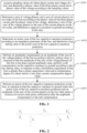
- the application provides a method for low capacitive reactance protection, as shown in FIG. 1 , the method includes the following operations A101 to A105.
- sampling values of a three-phase current and voltage of a line are acquired, and a phasor value of the three-phase current and a phasor value of the voltage are determined according to the sampling values.
- a sum of voltage phasors and a sum of current phasors on two sides of the line are determined according to the phasor value of the three-phase current and the phasor value of the voltage, a ratio of the sum of the voltage phasors to the sum of the current phasors on the two sides is determined, and a capacitive reactance to ground is determined according to the ratio.
- an action zone of the low capacitive reactance protection is determined according to an impedance parameter of the line, and a key setting value in the action zone of the low capacitive reactance protection is determined.
- an amplitude compensation is performed on an amplitude of the sum of the voltage phasors of the line according to the key setting value, in response to that the amplitude of the sum of the voltage phasors of the line is less than a preset amplitude value; a soft compensation is performed on the capacitive reactance to ground according to the key setting value, in response to that a distribution capacitance of the line is greater than a preset capacitance value and a compensation degree of a shunt reactor is less than a preset compensation degree value.
- an action of the low capacitive reactance protection is performed on the line, in response to that the capacitive reactance to ground enters the action zone of the low capacitive reactance protection and an amplitude of the sum of the current phasors on the two sides meets a criterion of current multi-point confirmation after the amplitude compensation or the soft compensation.
- the key setting value includes at least one of a reactance line setting value, a capacitive reactance line intercept setting value, a capacitive reactance line setting value, a resistance line setting value, or a negative resistance line setting value.
- the sum of the voltage phasors is determined according to phasor values of three-phase voltages on the two sides of the line, in response to that a Potential Transformer (PT) disconnection does not occur to the line; and the sum of the voltage phasors is determined according to an inherent parameter of the line and a phasor value of a voltage on one side of the line, in response to that the PT disconnection occurs on another side of the line.
- PT Potential Transformer
- the current multi-point confirmation is performed using an inverse time logic.
- the criterion of the current multi-point confirmation includes that a number of points for the current multi-point confirmation is determined according to the amplitude of the sum of the current phasors.
- a voltage phasor and a current phasor are calculated by a recursive algorithm for sampling values.
- f T ( t k ) is a sampling value at moment t k
- f T ( t k - N ) is a sampling value at moment t k-N
- N is a number of sampling points in one cycle of power frequency
- a k is a real part of a phasor calculated by the recursive algorithm for sampling values
- b k is an imaginary part of a phasor calculated by the recursive algorithm for sampling values
- ⁇ k is a phasor value calculated by the recursive algorithm for sampling values.
- sampling values of three-phase voltages on two sides of the line are u a ( t ), u b ( t ) and u c ( t ), and phasor values calculated by a Fourier recursive algorithm for sampling values are U ⁇ A , U ⁇ B and U ⁇ C .
- sampling values of three-phase currents on two sides of the line are i a ( t ), i b ( t ) and i c ( t ), and phasor values calculated by the Fourier recursive algorithm for sampling values are ⁇ A , ⁇ B and ⁇ C .
- a capacitive reactance to ground of an inherent parameter of the line is calculated as follows.
- U ⁇ 1 and U ⁇ 2 are voltages on two sides of the line
- U ⁇ ⁇ is a sum of voltage phasors on two sides of the line
- ⁇ 1 and ⁇ 2 are currents on two sides of the line
- ⁇ ⁇ is a sum of current phasors on two sides of the line
- Y b is an admittance of the line to ground
- Y 12 is an admittance of the line.
- a capacitive reactance to ground is indicated by the following formula:
- Z ⁇ is an impedance to ground
- R ⁇ is a real part of the impedance to ground, expressed as a resistance
- X ⁇ is an imaginary part of the impedance to ground, expressed as a reactance or capacitance.
- a reactance to ground is an inherent parameter of the line 2 X c during normal operation or an external fault
- X c is a capacitive reactance of the line.
- a protection action zone of the line is constructed as follows. An action zone of the low capacitive reactance protection is shown in FIG. 3 , and five key setting values in the action zone are X set- 1 , X set- 2 , X C , R set- 1 and R set- 2 .
- Z L 1 is an amplitude of impedance of the line
- k xset is a setting coefficient of the impedance of the line
- R xset is a margin setting value of a reactance line.
- R cset is a margin setting value of a capacitive reactance intercept
- k cset is a coefficient of the capacitive reactance intercept
- the third key setting value i.e., the capacitive reactance line setting values X C 3 and X C 4 are calculated by the following formula, where slope setting values are k 3 and k 4 , k 3 is a slope of the capacitive reactance line in a third quadrant; and k 4 is a slope of the capacitive reactance line in a fourth quadrant.
- slope setting values are k 3 and k 4
- k 3 is a slope of the capacitive reactance line in a third quadrant
- k 4 is a slope of the capacitive reactance line in a fourth quadrant.
- ⁇ X C 3 X set ⁇ 2 ⁇ k 3 R ⁇
- ⁇ X C 4 X set ⁇ 2 + k 4 R ⁇
- U ⁇
- is an amplitude of a sum of voltage phasors
- I min set is a minimum current for an identifiable fault
- R rset is a margin setting value of the resistance line.
- R set- 2 an absolute value of R set- 2 is the same as the reactance line setting value.
- the above setting values may be solidified in a relay protection device without manual setting.
- a process of voltage adaptive compensation is as follows.
- U N is a rated voltage
- k uset is a low voltage coefficient. While voltage compensation is performed adaptively, the action zone of the low capacitive reactance protection is adjusted adaptively, that is, value of X set -2 is adjusted adaptively, X set -2 is set according to the line shown in FIG. 4 .
- a process of current multi-point confirmation is as follows.
- logic of the current multi-point confirmation is constructed using an inverse time logic, the current confirmation is shown in FIG. 5 , and a criterion thereof is: I ⁇ ⁇ > I set
- the criterion of the current multi-point confirmation is tenable when the current confirmation criterion is met at N consecutive points.
- N When the setting value of the current confirmation criterion is large, there is a small number of confirmation points, that is, N is small.
- N When the setting value of the current confirmation criterion is small, there is a large number of confirmation points, that is, N is large.
- the current confirmation criterion is an action with consecutive 24 cumulative points.
- a process of soft compensation is as follows.
- a distribution capacitance of the line is too large and a compensation degree of a shunt reactor is low, a soft compensation technology is adopted to improve an identification ability of the low capacitive reactance protection.
- X c is a value of a capacitive reactance to ground before compensation
- jX L is a soft compensation reactance
- Z ' ⁇ is a capacitive reactance to ground after compensation.
- a treatment process of PT disconnection is as follows.
- U ⁇ 1 is a voltage on a side without disconnection
- k u is a voltage replacement setting value when PT disconnection occurs
- k u 0.9.
- a principle of a low capacitive reactance protection logic is shown in FIG. 6 .
- the capacitive reactance to ground Z' ⁇ enters the action zone of the low capacitive reactance protection after a fault occurs and compensation is performed by the soft compensation technology, and the criterion of the current multi-point confirmation is met, then an action of the low capacitive reactance protection is performed.
- the low capacitive reactance protection enters the action zone at 1.67ms when a three-phase fault occurs during system oscillation. 3-point confirmation is made to a current, and thus the low capacitive reactance protection functions at 3.33ms then exits.
- the result is shown in FIG. 11 .
- a simulation is performed for the AC transmission line with a series compensation capacitor installed.
- the low capacitive reactance protection enters the action zone at 2.5ms, 2-point confirmation is made to a current, and the low capacitive reactance protection functions at 3.33ms then exits.
- the result is shown in FIG. 14 .
- a simulation is performed for the AC transmission line where the new energy is transmitted through the flexible direct island mode, when an internal fault occurs, the low capacitive reactance protection enters the action zone at 4.17ms, a current multi-point confirmation is a 1-point confirmation, and thus the protection functions at 4.17ms then exits.
- the result is shown in FIG. 15 .
- the low capacitive reactance protection When a fault occurs to the transmission line through an 80052 transition resistor, the low capacitive reactance protection enters the action zone at 10.83ms, with a current of 0.6kA at this time, 12-point confirmation is made to the current, and the low capacitive reactance protection functions at 20ms then exits. The result is shown in FIG. 17 .
- the application further provides a system 200 for low capacitive reactance protection, as shown in FIG. 18 , the system includes a sampling part 201, a calculation part 202, a key setting value determination part 203, a compensation control part 204 and an action control part 205.
- the sampling part 201 is configured to acquire sampling values of a three-phase current and voltage of a line, and determine a phasor value of the three-phase current and a phasor value of the voltage according to the sampling values.
- the calculation part 202 is configured to determine a sum of voltage phasors and a sum of current phasors on two sides of the line according to the phasor value of the three-phase current and the phasor value of the voltage, determine a ratio of the sum of the voltage phasors to the sum of the current phasors on the two sides, and determine a capacitive reactance to ground according to the ratio.
- the key setting value determination part 203 is configured to determine an action zone of the low capacitive reactance protection according to an impedance parameter of the line, and determine a key setting value in the action zone of the low capacitive reactance protection.
- the compensation control part 204 is configured to perform an amplitude compensation on an amplitude of the sum of the voltage phasors of the line according to the key setting value, in response to that the amplitude of the sum of the voltage phasors of the line is less than a preset amplitude value; perform a soft compensation on the capacitive reactance to ground according to the key setting value, in response to that a distribution capacitance of the line is greater than a preset capacitance value and a compensation degree of a shunt reactor is less than a preset compensation degree value.
- the action control part 205 is configured to perform an action of the low capacitive reactance protection on the line, in response to that the capacitive reactance to ground enters the action zone of the low capacitive reactance protection and an amplitude of the sum of the current phasors on the two sides meets a criterion of current multi-point confirmation after the amplitude compensation or the soft compensation.
- the key setting value includes at least one of a reactance line setting value, a capacitive reactance line intercept setting value, a capacitive reactance line setting value, a resistance line setting value, or a negative resistance line setting value.
- the calculation part is further configured to: determine the sum of the voltage phasors according to phasor values of three-phase voltages on the two sides of the line, in response to that PT disconnection does not occur to the line; and determine the sum of the voltage phasors according to an inherent parameter of the line and a phasor value of a voltage on one side of the line, in response to that the PT disconnection occurs on another side of the line.
- the current multi-point confirmation of the action control part is performed using an inverse time logic.
- the criterion of the current multi-point confirmation of the action control part includes that a number of points for the current multi-point confirmation is determined according to the amplitude of the sum of the current phasors.
- the method of the application may accurately and quickly identify line faults and improve reliability of line protection, has a simple protection principle, a fast action speed and high sensitivity, and is not affected by system operation modes and fault types, and reliability and sensitivity of the method are superior to existing protection.
- the embodiments of the application may be provided as methods, systems or computer program products. Therefore, the application may take forms of embodiments with entirely hardware, embodiments with entirely software, or embodiments combining software with hardware aspects. Furthermore, the application may take a form of a computer program product implemented on one or more computer-available storage media (including, but not limited to a disk storage, a Compact Disk Read Only Memory (CD-ROM), an optical storage, etc.) containing computer-available program codes therein.
- the solutions in the embodiments of the application may be implemented in various computer languages, such as an object-oriented programming language Java, an interpreted script language JavaScript, etc.
- These computer program instructions may also be stored in a computer-readable memory which may guide a computer or other programmable data processing devices to operate in a specific manner, such that the instructions stored in the computer-readable memory generate a manufactured product including instruction devices, and the instruction devices implement functions specified in one or more flows of the flowcharts and/or one or more blocks of the block diagrams.
- These computer program instructions may also be loaded onto a computer or other programmable data processing devices, such that a series of operations are executed on the computer or other programmable devices to generate computer-implemented processing, and thus the instructions executed on the computer or other programmable devices provide operations for implementing functions specified in one or more flows of the flowcharts and/or one or more blocks of the block diagrams.
- the embodiment of the application provides a method and system for low capacitive reactance protection, a computer-readable storage medium, and a computer program product.
- the method includes the following operations. Sampling values of a three-phase current and voltage of a line are acquired, and a phasor value of the three-phase current and a phasor value of the voltage are determined according to the sampling values. A capacitive reactance to ground is determined according to a ratio. An action zone of the low capacitive reactance protection is determined according to an impedance parameter of the line, and a key setting value in the action zone of the low capacitive reactance protection is determined. An amplitude compensation or a soft compensation is performed.
- An action of the low capacitive reactance protection is performed on the line, in response to that the capacitive reactance to ground enters the action zone of the low capacitive reactance protection and an amplitude of the sum of the current phasors on two sides meets a criterion of current multi-point confirmation after the amplitude compensation or the soft compensation.
- the method of the embodiments of the application may accurately and quickly identify line faults, and improve reliability of line protection.
Landscapes
- Emergency Protection Circuit Devices (AREA)
Abstract
Description
- This application is filed based on and claims priority to
Chinese Patent application No. 202110235447.7 filed on March 3, 2021 - The application relates to the field of relay protection in a power system, and in particularly to a method and system for low capacitive reactance protection, a computer-readable storage medium, and a computer program product.
- With access of new energies and power electronics to a power grid, the power grid in China is facing serious challenges.
- First challenge: after the new energy is accessed, a short-circuit current is limited. Due to an influence of a control system strategy after a fault occurs to a new energy power supply, a fault current presents a characteristic of limited amplitude, which greatly reduces a sensitivity of a traditional protection principle which identifies the fault using characteristics of the fault current.
- Second challenge: when a flexible direct current (DC) is connected to an alternating current (AC) system, a fault current will present a draw-out characteristic, which will increase a braking current and weaken fault characteristics. The increase of the braking current and weakening of the fault characteristics will reduce a sensitivity of an existing protection, which will lead to the protection failing to operate and inability to quickly remove the fault, seriously affecting reliability of the power supply and stability of the system.
- Third challenge: in order to adapt to access and transmission of large-scale new energies such as wind power, photovoltaic or the like, and to solve prominent problems such as reactive power balance, voltage control or the like, a large number of power electronic devices with various kinds are adopted in the power grid, such as a Unified Power Flow Control (UPFC) device, a controllable shunt reactor, etc. A high proportion of power electronic devices are accessed to the power grid, which leads to significant changes in a structure of the power grid and fault characteristics, greatly reduces reliability of protection, leads to malfunction of the protection, and affects stability of the system.
- Existing transmission lines adopt a principle of current differential protection, which has the following shortcomings.
- Access of the new energies and the power electronic devices has changed the structure of the power grid. Furthermore, due to an influence of the device's own bearing capacity and characteristics of a control system thereof, fault characteristics of the power grid are weakened and the short-circuit current after the fault occurs is greatly reduced; when a fault occurs through a high transition resistor, a fault current will be less than a load current, the principle of current differential protection is difficult to adapt to complex and variable application scenarios of the power grid, an ability of fault identification is greatly reduced, and a sensitivity of the current differential protection is reduced.
- When the line is used as an outgoing line of a flexible direct system, due to functions of a flexible direct control system, the flexible direct system provides a draw-out short-circuit current when an internal fault occurs to the line, which increases the braking current and decreases an action current, presenting characteristics of an external fault. When series compensation is overcompensated, the same problems exist, and the principle of current differential protection is difficult to identify the fault with the draw-out characteristic, which leads to the differential protection failing to operate and reduction of reliability of the current differential protection in severe cases.
- In order to eliminate an influence of a capacitive current on the transmission line, the current differential protection must introduce a voltage to compensate the capacitive current. When the controllable shunt reactor is adopted in the line, a compensation method of the capacitive current is difficult to adapt to different control tap positions of the controllable shunt reactor, which will cause an action current of a part of the tap positions to be not equal to zero when the external fault occurs, generating a risk of malfunction, and reducing selectivity of the current differential protection.
- When a fault of a single-phase grounding through a transition resistance occurs to the line, a phase selector is difficult to identify the fault phase due to an influence of the load current, and there is a problem of tripping a three-phase line due to the fault of the single-phase.
- The application provides a method for low capacitive reactance protection, including the following operations.
- Sampling values of a three-phase current and voltage of a line are acquired, and a phasor value of the three-phase current and a phasor value of the voltage are determined according to the sampling values.
- A sum of voltage phasors and a sum of current phasors on two sides of the line are determined according to the phasor value of the three-phase current and the phasor value of the voltage, a ratio of the sum of the voltage phasors to the sum of the current phasors on the two sides is determined, and a capacitive reactance to ground is determined according to the ratio.
- An action zone of the low capacitive reactance protection is determined according to an impedance parameter of the line, and a key setting value in the action zone of the low capacitive reactance protection is determined.
- An amplitude compensation is performed on an amplitude of the sum of the voltage phasors of the line according to the key setting value, in response to that the amplitude of the sum of the voltage phasors of the line is less than a preset amplitude value; a soft compensation is performed on the capacitive reactance to ground according to the key setting value, in response to that a distribution capacitance of the line is greater than a preset capacitance value and a compensation degree of a shunt reactor is less than a preset compensation degree value.
- An action of the low capacitive reactance protection is performed on the line, in response to that the capacitive reactance to ground enters the action zone of the low capacitive reactance protection and an amplitude of the sum of the current phasors on the two sides meets a criterion of current multi-point confirmation after the amplitude compensation or the soft compensation.
- In some embodiments of the application, the key setting value may include at least one of a reactance line setting value, a capacitive reactance line intercept setting value, a capacitive reactance line setting value, a resistance line setting value, or a negative resistance line setting value.
- In some embodiments of the application, the sum of the voltage phasors may be determined according to phasor values of three-phase voltages on the two sides of the line, in response to that a Potential Transformer (PT) disconnection does not occur to the line; and the sum of the voltage phasors may be determined according to an inherent parameter of the line and a phasor value of a voltage on one side of the line, in response to that the PT disconnection occurs on another side of the line.
- In some embodiments of the application, the current multi-point confirmation may be performed using an inverse time logic.
- In some embodiments of the application, the criterion of the current multi-point confirmation may include that a number of points for the current multi-point confirmation is determined according to the amplitude of the sum of the current phasors.
- The application further provides a system for low capacitive reactance protection, including a sampling unit, a calculation part, a key setting value determination part, a compensation control part and an action control part.
- The sampling unit is configured to acquire sampling values of a three-phase current and voltage of a line, and determine a phasor value of the three-phase current and a phasor value of the voltage according to the sampling values.
- The calculation part is configured to determine a sum of voltage phasors and a sum of current phasors on two sides of the line according to the phasor value of the three-phase current and the phasor value of the voltage, determine a ratio of the sum of the voltage phasors to the sum of the current phasors on the two sides, and determine a capacitive reactance to ground according to the ratio.
- The key setting value determination part is configured to determine an action zone of the low capacitive reactance protection according to an impedance parameter of the line, and determine a key setting value in the action zone of the low capacitive reactance protection.
- The compensation control part is configured to perform an amplitude compensation on an amplitude of the sum of the voltage phasors of the line according to the key setting value, in response to that the amplitude of the sum of the voltage phasors of the line is less than a preset amplitude value; perform a soft compensation on the capacitive reactance to ground according to the key setting value, in response to that a distribution capacitance of the line is greater than a preset capacitance value and a compensation degree of a shunt reactor is less than a preset compensation degree value.
- The action control part is configured to perform an action of the low capacitive reactance protection on the line, in response to that the capacitive reactance to ground enters the action zone of the low capacitive reactance protection and an amplitude of the sum of the current phasors on the two sides meets a criterion of current multi-point confirmation after the amplitude compensation or the soft compensation.
- In some embodiments of the application, the key setting value may include at least one of a reactance line setting value, a capacitive reactance line intercept setting value, a capacitive reactance line setting value, a resistance line setting value, or a negative resistance line setting value.
- In some embodiments of the application, the calculation part may be further configured to: determine the sum of the voltage phasors according to phasor values of three-phase voltages on the two sides of the line, in response to that PT disconnection does not occur to the line; and determine the sum of the voltage phasors according to an inherent parameter of the line and a phasor value of a voltage on one side of the line, in response to that the PT disconnection occurs on another side of the line.
- In some embodiments of the application, the current multi-point confirmation of the action control part may be performed using an inverse time logic.
- In some embodiments of the application, the criterion of the current multi-point confirmation of the action control part may include that a number of points for the current multi-point confirmation is determined according to the amplitude of the sum of the current phasors.
- The method of the application has a simple principle, may accurately and quickly identify line faults and improve reliability of line protection, has a simple protection principle, a fast action speed and high sensitivity, and is not affected by system operation modes and fault types, and reliability and sensitivity of the method are superior to existing protection.
- An embodiment of the application provides a computer program product, including a computer program or instruction. Any one of the methods for low capacitive reactance protection is implemented when the computer program or instruction is executed by a processor.
- An embodiment of the application provides a computer-readable storage medium, having stored thereon a computer program. The computer program includes a program instruction, and the program instruction allows a processor to execute any one of the methods for low capacitive reactance protection when the program instruction is executed by the processor.
- The embodiments of the application have the following advantageous effects.
- The embodiments of the application provide a method and system for low capacitive reactance protection, a computer-readable storage medium, and a computer program product. The method includes the following operations. Sampling values of a three-phase current and voltage of a line are acquired, and a phasor value of the three-phase current and a phasor value of the voltage are determined according to the sampling values. A capacitive reactance to ground is determined according to a ratio. An action zone of the low capacitive reactance protection is determined according to an impedance parameter of the line, and a key setting value in the action zone of the low capacitive reactance protection is determined. An amplitude compensation or a soft compensation is performed. An action of the low capacitive reactance protection is performed on the line, in response to that the capacitive reactance to ground enters the action zone of the low capacitive reactance protection and an amplitude of the sum of the current phasors on two sides meets a criterion of current multi-point confirmation after the amplitude compensation or the soft compensation. In the method, the capacitive reactance to ground is determined according to the determined phasor value of the three-phase current and the determined phasor value of the voltage, the action zone of the low capacitive reactance protection is determined according to the impedance parameter of the line, the key setting value in the action zone of the low capacitive reactance protection is determined, and the action of the low capacitive reactance protection is performed on the line after compensation and meeting a condition, so that line faults are accurately and quickly identified, and reliability of line protection is improved.
-
-
FIG. 1 is a flowchart of a method for low capacitive reactance protection according to the application. -
FIG. 2 is an equivalent diagram of a transmission line of a method for low capacitive reactance protection according to the application. -
FIG. 3 is a line diagram of an action zone of low capacitive reactance protection of a method for low capacitive reactance protection according to the application. -
FIG. 4 is a line diagram of determining a capacitive reactance line intercept setting value by a method for low capacitive reactance protection according to the application. -
FIG. 5 is a diagram of current multi-point confirmation of a method for low capacitive reactance protection according to the application. -
FIG. 6 is a logic diagram of low capacitive reactance protection of a method for low capacitive reactance protection according to the application. -
FIG. 7 is a line diagram of an action result of low capacitive reactance protection for an internal fault by a method for low capacitive reactance protection according to the application. -
FIG. 8 is a line diagram of an action result of low capacitive reactance protection for an external fault by a method for low capacitive reactance protection according to the application. -
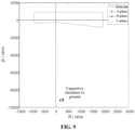
FIG. 9 is a line diagram of an action result of low capacitive reactance protection for normal operation by a method for low capacitive reactance protection according to the application. -
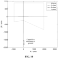
FIG. 10 is a line diagram of an action result of low capacitive reactance protection for system oscillation by a method for low capacitive reactance protection according to the application. -
FIG. 11 is a line diagram of an action result of low capacitive reactance protection for an internal fault occurred during system oscillation, by a method for low capacitive reactance protection according to the application. -
FIG. 12 is a line diagram of an action result of low capacitive reactance protection for an internal fault occurred when a controllable reactor is 100% put into operation, by a method for low capacitive reactance protection according to the application. -
FIG. 13 is a line diagram of an action result of low capacitive reactance protection for an internal fault occurred when a controllable reactor is 67% put into operation, by a method for low capacitive reactance protection according to the application. -
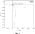
FIG. 14 is a line diagram of an action result of low capacitive reactance protection for an internal fault occurred to a line with a series compensation capacitor installed, by a method for low capacitive reactance protection according to the application. -
FIG. 15 is a line diagram of an action result of low capacitive reactance protection for a fault occurred to an AC transmission line where a new energy is transmitted through a flexible direct island mode, by a method for low capacitive reactance protection according to the application. -
FIG. 16 is a line diagram of an action result of low capacitive reactance protection for an internal fault occurred to a disconnection phase when PT single-phase disconnection occurs to a line, by a method for low capacitive reactance protection according to the application. -
FIG. 17 is a line diagram of an action result of low capacitive reactance protection for a fault occurred to phase A through an 800Ω transition resistor, by a method for low capacitive reactance protection according to the application. -
FIG. 18 is a structural diagram of a system for low capacitive reactance protection according to the application. - In order to make the purpose, technical solutions and advantages of the embodiments of the application clearer, the technical solutions of the embodiments of the application will be clearly and completely described below with reference to the drawings in the embodiments of the application. It is apparent that the described embodiments are only part of the embodiments of the application, rather than all of the embodiments. Components of the embodiments of the application generally described and shown in the drawings here may be arranged and designed in various different configurations. Therefore, the following detailed descriptions of the embodiments of the application provided in the drawings are not intended to limit the scope of protection of the application, instead, only intended to represent selected embodiments of the application. Based on the embodiments of the application, all other embodiments obtained by those skilled in the art without paying any creative work fall within the scope of protection of the application.
- Exemplary embodiments of the application are described with reference to the drawings. However, the application may be implemented in many different forms and is not limited to the embodiments described here. These embodiments are provided to thoroughly and completely disclose the application and fully convey the scope of the application to those skilled in the art. Terms in the exemplary embodiments represented in the drawings are not limitations of the application. In the drawings, the same units/components are marked with the same reference symbol.
- Unless otherwise specified, terms used here (including technological terms) have meanings commonly understood by those skilled in the art. Furthermore, it may be understood that terms defined in commonly used dictionaries should be understood as having meanings consistent with the context of their relevant fields, and should not be understood as having idealistic or overly formal meanings.
- The application provides a method for low capacitive reactance protection, as shown in
FIG. 1 , the method includes the following operations A101 to A105. - At A101, sampling values of a three-phase current and voltage of a line are acquired, and a phasor value of the three-phase current and a phasor value of the voltage are determined according to the sampling values.
- At A102, a sum of voltage phasors and a sum of current phasors on two sides of the line are determined according to the phasor value of the three-phase current and the phasor value of the voltage, a ratio of the sum of the voltage phasors to the sum of the current phasors on the two sides is determined, and a capacitive reactance to ground is determined according to the ratio.
- At A103, an action zone of the low capacitive reactance protection is determined according to an impedance parameter of the line, and a key setting value in the action zone of the low capacitive reactance protection is determined.
- At A104, an amplitude compensation is performed on an amplitude of the sum of the voltage phasors of the line according to the key setting value, in response to that the amplitude of the sum of the voltage phasors of the line is less than a preset amplitude value; a soft compensation is performed on the capacitive reactance to ground according to the key setting value, in response to that a distribution capacitance of the line is greater than a preset capacitance value and a compensation degree of a shunt reactor is less than a preset compensation degree value.
- At A105, an action of the low capacitive reactance protection is performed on the line, in response to that the capacitive reactance to ground enters the action zone of the low capacitive reactance protection and an amplitude of the sum of the current phasors on the two sides meets a criterion of current multi-point confirmation after the amplitude compensation or the soft compensation.
- In some embodiments of the application, the key setting value includes at least one of a reactance line setting value, a capacitive reactance line intercept setting value, a capacitive reactance line setting value, a resistance line setting value, or a negative resistance line setting value.
- In some embodiments of the application, the sum of the voltage phasors is determined according to phasor values of three-phase voltages on the two sides of the line, in response to that a Potential Transformer (PT) disconnection does not occur to the line; and the sum of the voltage phasors is determined according to an inherent parameter of the line and a phasor value of a voltage on one side of the line, in response to that the PT disconnection occurs on another side of the line.
- In some embodiments of the application, the current multi-point confirmation is performed using an inverse time logic.
- In some embodiments of the application, the criterion of the current multi-point confirmation includes that a number of points for the current multi-point confirmation is determined according to the amplitude of the sum of the current phasors.
- In some embodiments of the application, the application is further described below in conjunction with the embodiments: a voltage phasor and a current phasor are calculated by a recursive algorithm for sampling values. The recursive algorithm for sampling values is indicated by the following formulas:


- In formula (1) and formula (2), fT (tk ) is a sampling value at moment tk , fT (t k-N ) is a sampling value at moment tk-N , N is a number of sampling points in one cycle of power frequency, ak is a real part of a phasor calculated by the recursive algorithm for sampling values, bk is an imaginary part of a phasor calculated by the recursive algorithm for sampling values, and Ẋk is a phasor value calculated by the recursive algorithm for sampling values.
- In some embodiments of the application, sampling values of three-phase voltages on two sides of the line are ua (t), ub (t) and uc (t), and phasor values calculated by a Fourier recursive algorithm for sampling values are U̇A, U̇B and U̇C .
- In some embodiments of the application, sampling values of three-phase currents on two sides of the line are ia (t), ib (t) and ic (t), and phasor values calculated by the Fourier recursive algorithm for sampling values are İA, İB and İC.
- In some embodiments of the application, a capacitive reactance to ground of an inherent parameter of the line is calculated as follows. By equivalence of a transmission line as shown in
FIG. 2 , it may obtain the following formula:
- In formula (4), U̇ 1 and U̇ 2 are voltages on two sides of the line, U̇ε is a sum of voltage phasors on two sides of the line, İ 1 and İ 2 are currents on two sides of the line, İε is a sum of current phasors on two sides of the line, Yb is an admittance of the line to ground, and Y 12 is an admittance of the line.
- In some embodiments of the application, a capacitive reactance to ground is indicated by the following formula:

- In formula (5), Zε is an impedance to ground; Rε is a real part of the impedance to ground, expressed as a resistance; and Xε is an imaginary part of the impedance to ground, expressed as a reactance or capacitance. A reactance to ground is an inherent parameter of the line 2Xc during normal operation or an external fault, and Xc is a capacitive reactance of the line.
- In some embodiments of the application, a protection action zone of the line is constructed as follows. An action zone of the low capacitive reactance protection is shown in
FIG. 3 , and five key setting values in the action zone are X set-1 , X set-2 , XC, R set-1 and R set-2. - In some embodiments of the application, the first key setting value, i.e., the reactance line setting value X set-1 is calculated by the following formula:

- In formula (5-1), Z L1 is an amplitude of impedance of the line; kxset is a setting coefficient of the impedance of the line; and Rxset is a margin setting value of a reactance line.
- In some embodiments of the application, the second key setting value, i.e., the capacitive reactance line intercept setting value X set-2 is calculated by the following formula:

- In formula (5-2), Rcset is a margin setting value of a capacitive reactance intercept; and kcset is a coefficient of the capacitive reactance intercept.
- In some embodiments of the application, the third key setting value, i.e., the capacitive reactance line setting values X C3 and X C4 are calculated by the following formula, where slope setting values are k 3 and k 4, k 3 is a slope of the capacitive reactance line in a third quadrant; and k 4 is a slope of the capacitive reactance line in a fourth quadrant.

- In some embodiments of the application, the fourth key setting value, i.e., the resistance line setting value R set-1 is calculated by the following formula:

- In formula (5-4), U Σ = |U Σ| is an amplitude of a sum of voltage phasors; Imin set is a minimum current for an identifiable fault; and Rrset is a margin setting value of the resistance line.
- In some embodiments of the application, the fifth key setting value, i.e., the negative resistance line setting value R set-2 is calculated by the following formula:

- It may be understood that an absolute value of R set-2 is the same as the reactance line setting value. The above setting values may be solidified in a relay protection device without manual setting.
- In some embodiments of the application, a process of voltage adaptive compensation is as follows. In order to prevent protection malfunction caused by a too small voltage of an external fault of a single power line, an adaptive compensation is performed on the sum of the voltage phasors when an amplitude of the sum of the voltage phasors is too low, and the compensation method is indicated by the following formula:

- In formula (6), UN is a rated voltage, and kuset is a low voltage coefficient. While voltage compensation is performed adaptively, the action zone of the low capacitive reactance protection is adjusted adaptively, that is, value of X set-2 is adjusted adaptively, X set-2 is set according to the line shown in
FIG. 4 . - That is, when |U Σ| = 0,


- In some embodiments of the application, a process of current multi-point confirmation is as follows. In order to prevent protection malfunction in a transient process of an external fault, logic of the current multi-point confirmation is constructed using an inverse time logic, the current confirmation is shown in
FIG. 5 , and a criterion thereof is:
- In formula (7), |İε | is an amplitude of the sum of current phasors, and Iset is a setting value of the current confirmation criterion.
- In some embodiments of the application, the criterion of the current multi-point confirmation is tenable when the current confirmation criterion is met at N consecutive points. When the setting value of the current confirmation criterion is large, there is a small number of confirmation points, that is, N is small. When the setting value of the current confirmation criterion is small, there is a large number of confirmation points, that is, N is large.
- In some embodiments of the application, the current confirmation criterion is an action with consecutive 24 cumulative points.
- When the amplitude of the sum of the current phasors is greater than 3kA, 1 point is counted as 24 cumulative points.
- When the amplitude of the sum of the current phasors is greater than 2kA, 1 point is counted as 12 cumulative points.
- When the amplitude of the sum of the current phasors is greater than 1kA, 1 point is counted as 6 cumulative points.
- When the amplitude of the sum of the current phasors is greater than 0.8 kA, 1 point is counted as 3 cumulative points.
- When the amplitude of the sum of the current phasors is greater than 0.6 kA, 1 point is counted as 2 cumulative points.
- When the amplitude of the sum of the current phasors is less than 0.6 kA, 1 point is counted as 1 cumulative point.
- In some embodiments of the application, a process of soft compensation is as follows. When a distribution capacitance of the line is too large and a compensation degree of a shunt reactor is low, a soft compensation technology is adopted to improve an identification ability of the low capacitive reactance protection. The compensation method is indicated by the following formula:

- In formula (8), Xc is a value of a capacitive reactance to ground before compensation, X'c is an expected value of a capacitive reactance to ground after the soft compensation, preferably X'c = 4kΩ, jXL is a soft compensation reactance, and Z' ε is a capacitive reactance to ground after compensation.
- In some embodiments of the application, a treatment process of PT disconnection is as follows. When PT disconnection occurs on one side of the line, a voltage on this side is replaced by a voltage which is ku times the rated voltage. That is, when PT disconnection occurs on one side of the line, a sum of the voltage phasors is calculated by the following formula:

- In formula (9), U̇ 1 is a voltage on a side without disconnection, and ku is a voltage replacement setting value when PT disconnection occurs, ku = 0.9.
- In some embodiments of the application, a principle of a low capacitive reactance protection logic is shown in
FIG. 6 . When the capacitive reactance to ground Z'ε enters the action zone of the low capacitive reactance protection after a fault occurs and compensation is performed by the soft compensation technology, and the criterion of the current multi-point confirmation is met, then an action of the low capacitive reactance protection is performed. - In some embodiments of the application, examples are provided below for detailed explanations.
- 1. Normal operation of a conventional transmission line, an internal fault occurs to a line and an external fault occurs to the line.
- When an internal fault occurs to a conventional transmission line, low capacitive reactance protection is simulated, and the low capacitive reactance protection enters the action zone at 1.67ms. 3-point confirmation is made to a current, and the protection functions at 3.33ms then exits. The result is shown in
FIG. 7 . - When an external fault occurs to a conventional transmission line, low capacitive reactance protection is far away from the action zone, and the protection does not function. The result is shown in
FIG. 8 . - When a conventional transmission line operates normally, a calculation result of a capacitive reactance to ground is -j9000 Ω. Low capacitive reactance protection is far away from the action zone, and the protection does not function. The result is shown in
FIG. 9 . - 2. System oscillation and a fault occurs to a line during oscillation.
- A simulation is performed for a 400km line (without a shunt reactor installed), a capacitive reactance to ground is j2000S2 during normal operation. When system oscillation occurs, the capacitive reactance to ground remains unchanged at j2000S2. The low capacitive reactance protection does not function. The result is shown in
FIG. 10 . - A simulation is performed for a 400km line (without a shunt reactor installed). The low capacitive reactance protection enters the action zone at 1.67ms when a three-phase fault occurs during system oscillation. 3-point confirmation is made to a current, and thus the low capacitive reactance protection functions at 3.33ms then exits. The result is shown in
FIG. 11 . - 3. Fault occurs to an AC transmission line with a controllable shunt reactor installed.
- (3.1) A simulation is performed for a line with a controllable reactor. When the controllable reactor is 100% put into operation, an internal fault occurs to the transmission line, and the low capacitive reactance protection enters the action zone at 2.5ms. 2-point confirmation is made to a current, and the low capacitive reactance protection functions at 3.33ms then exits. The result is shown in
FIG. 12 . - (3.2) A simulation is performed for a line with a controllable reactor. When the controllable reactor is 67% put into operation, an internal fault occurs to the transmission line, and the low capacitive reactance protection enters the action zone at 2.5ms. 2-point confirmation is made to a current, and the low capacitive reactance protection functions at 3.33ms then exits. The result is shown in
FIG. 13 . - 4. Fault occurs to an AC transmission line with a series compensation capacitor installed.
- A simulation is performed for the AC transmission line with a series compensation capacitor installed. When an internal fault occurs, the low capacitive reactance protection enters the action zone at 2.5ms, 2-point confirmation is made to a current, and the low capacitive reactance protection functions at 3.33ms then exits. The result is shown in
FIG. 14 . - 5. Fault occurs to an AC transmission line where a new energy is transmitted through a flexible direct island mode.
- A simulation is performed for the AC transmission line where the new energy is transmitted through the flexible direct island mode, when an internal fault occurs, the low capacitive reactance protection enters the action zone at 4.17ms, a current multi-point confirmation is a 1-point confirmation, and thus the protection functions at 4.17ms then exits. The result is shown in
FIG. 15 . - 6. Performance of low capacitive reactance protection in case of PT disconnection.
- When PT single-phase disconnection occurs on one side of the transmission line, an internal fault occurs to the disconnection phase, the low capacitive reactance protection enters the action zone at 1.67ms, 3-point confirmation is made to a current, and the low capacitive reactance protection functions at 3.33ms then exits. The result is shown in
FIG. 16 . - 7. Performance of low capacitive reactance protection in case of a fault occurred through a high transition resistor.
- When a fault occurs to the transmission line through an 80052 transition resistor, the low capacitive reactance protection enters the action zone at 10.83ms, with a current of 0.6kA at this time, 12-point confirmation is made to the current, and the low capacitive reactance protection functions at 20ms then exits. The result is shown in
FIG. 17 . - The application further provides a
system 200 for low capacitive reactance protection, as shown inFIG. 18 , the system includes asampling part 201, acalculation part 202, a key settingvalue determination part 203, acompensation control part 204 and anaction control part 205. - The
sampling part 201 is configured to acquire sampling values of a three-phase current and voltage of a line, and determine a phasor value of the three-phase current and a phasor value of the voltage according to the sampling values. - The
calculation part 202 is configured to determine a sum of voltage phasors and a sum of current phasors on two sides of the line according to the phasor value of the three-phase current and the phasor value of the voltage, determine a ratio of the sum of the voltage phasors to the sum of the current phasors on the two sides, and determine a capacitive reactance to ground according to the ratio. - The key setting
value determination part 203 is configured to determine an action zone of the low capacitive reactance protection according to an impedance parameter of the line, and determine a key setting value in the action zone of the low capacitive reactance protection. - The
compensation control part 204 is configured to perform an amplitude compensation on an amplitude of the sum of the voltage phasors of the line according to the key setting value, in response to that the amplitude of the sum of the voltage phasors of the line is less than a preset amplitude value; perform a soft compensation on the capacitive reactance to ground according to the key setting value, in response to that a distribution capacitance of the line is greater than a preset capacitance value and a compensation degree of a shunt reactor is less than a preset compensation degree value. - The
action control part 205 is configured to perform an action of the low capacitive reactance protection on the line, in response to that the capacitive reactance to ground enters the action zone of the low capacitive reactance protection and an amplitude of the sum of the current phasors on the two sides meets a criterion of current multi-point confirmation after the amplitude compensation or the soft compensation. - In some embodiments of the application, the key setting value includes at least one of a reactance line setting value, a capacitive reactance line intercept setting value, a capacitive reactance line setting value, a resistance line setting value, or a negative resistance line setting value.
- In some embodiments of the application, the calculation part is further configured to: determine the sum of the voltage phasors according to phasor values of three-phase voltages on the two sides of the line, in response to that PT disconnection does not occur to the line; and determine the sum of the voltage phasors according to an inherent parameter of the line and a phasor value of a voltage on one side of the line, in response to that the PT disconnection occurs on another side of the line.
- In some embodiments of the application, the current multi-point confirmation of the action control part is performed using an inverse time logic.
- In some embodiments of the application, the criterion of the current multi-point confirmation of the action control part includes that a number of points for the current multi-point confirmation is determined according to the amplitude of the sum of the current phasors.
- The method of the application may accurately and quickly identify line faults and improve reliability of line protection, has a simple protection principle, a fast action speed and high sensitivity, and is not affected by system operation modes and fault types, and reliability and sensitivity of the method are superior to existing protection.
- It may be understood by those skilled in the art that the embodiments of the application may be provided as methods, systems or computer program products. Therefore, the application may take forms of embodiments with entirely hardware, embodiments with entirely software, or embodiments combining software with hardware aspects. Furthermore, the application may take a form of a computer program product implemented on one or more computer-available storage media (including, but not limited to a disk storage, a Compact Disk Read Only Memory (CD-ROM), an optical storage, etc.) containing computer-available program codes therein. The solutions in the embodiments of the application may be implemented in various computer languages, such as an object-oriented programming language Java, an interpreted script language JavaScript, etc.
- The application is described with reference to flowcharts and/or block diagrams of methods, devices (systems) and computer program products according to the embodiments of the application. It should be understood that computer program instructions may implement each flow and/or block in the flowcharts and/or the block diagrams, as well as combinations of flows and/or blocks in the flowcharts and/or the block diagrams. These computer program instructions may be provided to processors of a general purpose computer, a specialized computer, an embedded processor or other programmable data processing devices to generate a machine, such that instructions executed by the processors of the computer or other programmable data processing devices generate a device configured to implement functions specified in one or more flows of the flowcharts and/or one or more blocks of the block diagrams.
- These computer program instructions may also be stored in a computer-readable memory which may guide a computer or other programmable data processing devices to operate in a specific manner, such that the instructions stored in the computer-readable memory generate a manufactured product including instruction devices, and the instruction devices implement functions specified in one or more flows of the flowcharts and/or one or more blocks of the block diagrams.
- These computer program instructions may also be loaded onto a computer or other programmable data processing devices, such that a series of operations are executed on the computer or other programmable devices to generate computer-implemented processing, and thus the instructions executed on the computer or other programmable devices provide operations for implementing functions specified in one or more flows of the flowcharts and/or one or more blocks of the block diagrams.
- Although preferred embodiments of the application have been described, those skilled in the art may make additional changes and modifications to these embodiments once they have knowledge of basic inventive concepts. Therefore, the appended claims are intended to be interpreted to include the preferred embodiments and all changes and modifications falling within the scope of the application.
- It is apparent that those skilled in the art may make various modifications and variations to the application without departing from the spirit and scope of the application. In this way, when these modifications and variations of the application fall within the scope of the claims of the application and their equivalent technologies, the application also intends to include these modifications and variations.
- The embodiment of the application provides a method and system for low capacitive reactance protection, a computer-readable storage medium, and a computer program product. The method includes the following operations. Sampling values of a three-phase current and voltage of a line are acquired, and a phasor value of the three-phase current and a phasor value of the voltage are determined according to the sampling values. A capacitive reactance to ground is determined according to a ratio. An action zone of the low capacitive reactance protection is determined according to an impedance parameter of the line, and a key setting value in the action zone of the low capacitive reactance protection is determined. An amplitude compensation or a soft compensation is performed. An action of the low capacitive reactance protection is performed on the line, in response to that the capacitive reactance to ground enters the action zone of the low capacitive reactance protection and an amplitude of the sum of the current phasors on two sides meets a criterion of current multi-point confirmation after the amplitude compensation or the soft compensation. The method of the embodiments of the application may accurately and quickly identify line faults, and improve reliability of line protection.
Claims (12)
- A method for low capacitive reactance protection, comprising:acquiring sampling values of a three-phase current and voltage of a line, and determining a phasor value of the three-phase current and a phasor value of the voltage according to the sampling values;determining a sum of voltage phasors and a sum of current phasors on two sides of the line according to the phasor value of the three-phase current and the phasor value of the voltage, determining a ratio of the sum of the voltage phasors to the sum of the current phasors on the two sides, and determining a capacitive reactance to ground according to the ratio;determining an action zone of the low capacitive reactance protection according to an impedance parameter of the line, and determining a key setting value in the action zone of the low capacitive reactance protection;performing an amplitude compensation on an amplitude of the sum of the voltage phasors of the line according to the key setting value, in response to that the amplitude of the sum of the voltage phasors of the line is less than a preset amplitude value; performing a soft compensation on the capacitive reactance to ground according to the key setting value, in response to that a distribution capacitance of the line is greater than a preset capacitance value and a compensation degree of a shunt reactor is less than a preset compensation degree value; andperforming an action of the low capacitive reactance protection on the line, in response to that the capacitive reactance to ground enters the action zone of the low capacitive reactance protection and an amplitude of the sum of the current phasors on the two sides meets a criterion of current multi-point confirmation after the amplitude compensation or the soft compensation.
- The method of claim 1, wherein the key setting value comprises at least one of a reactance line setting value, a capacitive reactance line intercept setting value, a capacitive reactance line setting value, a resistance line setting value, or a negative resistance line setting value.
- The method of claim 1, wherein the sum of the voltage phasors is determined according to phasor values of three-phase voltages on the two sides of the line, in response to that a Potential Transformer (PT) disconnection does not occur to the line; and the sum of the voltage phasors is determined according to an inherent parameter of the line and a phasor value of a voltage on one side of the line, in response to that the PT disconnection occurs on another side of the line.
- The method of claim 1, wherein the current multi-point confirmation is performed using an inverse time logic.
- The method of claim 1, wherein the criterion of the current multi-point confirmation is specifically that a number of points for the current multi-point confirmation is determined according to the amplitude of the sum of the current phasors.
- A system for low capacitive reactance protection, comprising:a sampling unit, configured to acquire sampling values of a three-phase current and voltage of a line, and determine a phasor value of the three-phase current and a phasor value of the voltage according to the sampling values;a calculation part, configured to determine a sum of voltage phasors and a sum of current phasors on two sides of the line according to the phasor value of the three-phase current and the phasor value of the voltage, determine a ratio of the sum of the voltage phasors to the sum of the current phasors on the two sides, and determine a capacitive reactance to ground according to the ratio;a key setting value determination part, configured to determine an action zone of the low capacitive reactance protection according to an impedance parameter of the line, and determine a key setting value in the action zone of the low capacitive reactance protection;a compensation control part, configured to perform an amplitude compensation on an amplitude of the sum of the voltage phasors of the line according to the key setting value, in response to that the amplitude of the sum of the voltage phasors of the line is less than a preset amplitude value; perform a soft compensation on the capacitive reactance to ground according to the key setting value, in response to that a distribution capacitance of the line is greater than a preset capacitance value and a compensation degree of a shunt reactor is less than a preset compensation degree value; andan action control part, configured to perform an action of the low capacitive reactance protection on the line, in response to that the capacitive reactance to ground enters the action zone of the low capacitive reactance protection and an amplitude of the sum of the current phasors on the two sides meets a criterion of current multi-point confirmation after the amplitude compensation or the soft compensation.
- The system of claim 6, wherein the key setting value comprises at least one of a reactance line setting value, a capacitive reactance line intercept setting value, a capacitive reactance line setting value, a resistance line setting value, or a negative resistance line setting value.
- The system of claim 6, wherein the calculation part is further configured to:determine the sum of the voltage phasors according to phasor values of three-phase voltages on the two sides of the line, in response to that a Potential Transformer (PT) disconnection does not occur to the line; anddetermine the sum of the voltage phasors according to an inherent parameter of the line and a phasor value of a voltage on one side of the line, in response to that the PT disconnection occurs on another side of the line.
- The system of claim 6, wherein the action control part is configured to perform the current multi-point confirmation using an inverse time logic.
- The system of claim 6, wherein the criterion of the current multi-point confirmation is specifically that a number of points for the current multi-point confirmation is determined according to the amplitude of the sum of the current phasors.
- A computer program product, comprising a computer program or instruction, wherein the method of any one of claims 1 to 5 is implemented when the computer program or instruction is executed by a processor.
- A computer-readable storage medium, having stored thereon a computer program, the computer program comprising a program instruction, and the program instruction allowing a processor to execute the method of any one of claims 1 to 5 when the program instruction is executed by the processor.
Applications Claiming Priority (2)
| Application Number | Priority Date | Filing Date | Title |
|---|---|---|---|
| CN202110235447.7A CN113131447B (en) | 2021-03-03 | 2021-03-03 | Low capacitive reactance protection method and system |
| PCT/CN2022/075394 WO2022183885A1 (en) | 2021-03-03 | 2022-02-07 | Low-capacitive-reactance protection method and system, and computer-readable storage medium and computer program product |
Publications (3)
| Publication Number | Publication Date |
|---|---|
| EP4297218A1 true EP4297218A1 (en) | 2023-12-27 |
| EP4297218A4 EP4297218A4 (en) | 2024-09-25 |
| EP4297218B1 EP4297218B1 (en) | 2025-12-10 |
Family
ID=76772485
Family Applications (1)
| Application Number | Title | Priority Date | Filing Date |
|---|---|---|---|
| EP22762352.7A Active EP4297218B1 (en) | 2021-03-03 | 2022-02-07 | Low-capacitive-reactance protection method and system, and computer-readable storage medium and computer program product |
Country Status (3)
| Country | Link |
|---|---|
| EP (1) | EP4297218B1 (en) |
| CN (1) | CN113131447B (en) |
| WO (1) | WO2022183885A1 (en) |
Families Citing this family (4)
| Publication number | Priority date | Publication date | Assignee | Title |
|---|---|---|---|---|
| CN113131447B (en) * | 2021-03-03 | 2022-11-25 | 中国电力科学研究院有限公司 | Low capacitive reactance protection method and system |
| CN115902336A (en) * | 2022-03-01 | 2023-04-04 | 中国电力科学研究院有限公司 | A method and system for calculating line capacitive reactance based on compensation voltage |
| CN116111564A (en) * | 2022-07-22 | 2023-05-12 | 中国电力科学研究院有限公司 | Line differential protection method and system for vertical and horizontal hybrid braking |
| CN119253548B (en) * | 2024-09-06 | 2025-11-18 | 中国电力科学研究院有限公司 | An adaptive differential protection method and system for new energy grid-connected lines |
Family Cites Families (8)
| Publication number | Priority date | Publication date | Assignee | Title |
|---|---|---|---|---|
| US5796258A (en) * | 1997-01-30 | 1998-08-18 | Abb Power T&D Company, Inc. | Adaptive quadrilateral characteristic distance relay |
| CN100574035C (en) * | 2008-01-25 | 2009-12-23 | 烟台东方电子信息产业股份有限公司 | A Judgment Method for Transmission Line Pilot Protection Based on Synthetic Impedance |
| CN101478147B (en) * | 2009-01-15 | 2012-04-18 | 烟台东方电子信息产业股份有限公司 | Zero sequence comprehensive impedance longitudinal protection judgment method |
| CN101593970B (en) * | 2009-06-24 | 2011-05-11 | 河南省电力公司新乡供电公司 | Method for compensating time-domain capacitive current for double-circuit line on same pole |
| CN101741070B (en) * | 2010-01-11 | 2012-04-25 | 山东大学 | Line longitudinal protection method based on current and voltage at both ends |
| JP5537318B2 (en) * | 2010-07-26 | 2014-07-02 | 株式会社東芝 | Accident section discrimination means for distribution lines |
| US20170227595A1 (en) * | 2016-02-08 | 2017-08-10 | General Electric Company | Systems and Methods for Determining a Fault Location in a Three-Phase Series-Compensated Power Transmission Line |
| CN113131447B (en) * | 2021-03-03 | 2022-11-25 | 中国电力科学研究院有限公司 | Low capacitive reactance protection method and system |
-
2021
- 2021-03-03 CN CN202110235447.7A patent/CN113131447B/en active Active
-
2022
- 2022-02-07 EP EP22762352.7A patent/EP4297218B1/en active Active
- 2022-02-07 WO PCT/CN2022/075394 patent/WO2022183885A1/en not_active Ceased
Also Published As
| Publication number | Publication date |
|---|---|
| WO2022183885A1 (en) | 2022-09-09 |
| CN113131447A (en) | 2021-07-16 |
| EP4297218A4 (en) | 2024-09-25 |
| EP4297218B1 (en) | 2025-12-10 |
| CN113131447B (en) | 2022-11-25 |
Similar Documents
| Publication | Publication Date | Title |
|---|---|---|
| EP4297218B1 (en) | Low-capacitive-reactance protection method and system, and computer-readable storage medium and computer program product | |
| US11002780B1 (en) | Renewable energy source system having a high-frequency fault component based distance protection system | |
| US12348036B2 (en) | Adaptive arc suppression method for ground faults in a combined active and passive distribution network | |
| Musa et al. | A covariance indices based method for fault detection and classification in a power transmission system during power swing | |
| CN112467733B (en) | A kind of active power injection full compensation arc suppression coil active withdrawal method | |
| WO2023245866A1 (en) | Fault identification method and system based on full-time-domain abrupt change information, electronic device, and computer-readable storage medium | |
| Jalilian et al. | Distance protection of transmission lines in presence of inverter-based resources: A new earth fault detection scheme during asymmetrical power swings | |
| Chabanloo et al. | An accurate method for overcurrent–distance relays coordination in the presence of transient states of fault currents | |
| CN117110783A (en) | Fault direction identification method and system based on current waveform distortion characteristics | |
| Lin et al. | Electromagnetic transient analysis and novel protective relaying techniques for power transformers | |
| Thakur et al. | Modal voltage decomposition-based passive method for islanding detection using variational mode decomposition in active distribution network | |
| Samal et al. | A novel sequence component based fault detection index for microgrid protection | |
| Samal et al. | A new differential index-based fault detection scheme for microgrids | |
| Samet et al. | Evaluation of directional relay algorithms in presence of wind turbines and fault current limiters | |
| US20250192547A1 (en) | Arc suppression method, system, and medium for distribution network faults based on closed-loop self-healing control | |
| EP4350918B1 (en) | Method and system for identifying dominant overvoltage of a high-proportion new energy power system, electronic device, storage medium, and computer program product | |
| Shalash et al. | C. B interrupt duty reduction based controlling TRV and symmetrical breaking current | |
| Patel et al. | Transmission line protection philosophy | |
| Ayvaz | An investigation of the impact of distributed generation penetration on directional overcurrent relay coordination in a distribution network | |
| Gao et al. | Flexible DC transmission line fault type identification scheme based on Pearson correlation coefficient | |
| Liu et al. | Analysis of the Depth of Positive Sequence Voltage Sags in Distribution Network Faults and Their Effects on New Energy-Type Equipment | |
| Cao et al. | Improving performances of distance protection for centralized DFIG wind plant using the resistive-type SFCL | |
| Ansari et al. | A data driven based adaptive unit protection for transmission line integrated with large penetrated wind farms | |
| CN115728591B (en) | Fault phase selection method suitable for high-voltage transmission line of high-proportion new energy system | |
| CN119492955B (en) | A method for determining the direction of power grid short-circuit fault based on current variation characteristics |
Legal Events
| Date | Code | Title | Description |
|---|---|---|---|
| STAA | Information on the status of an ep patent application or granted ep patent |
Free format text: STATUS: THE INTERNATIONAL PUBLICATION HAS BEEN MADE |
|
| PUAI | Public reference made under article 153(3) epc to a published international application that has entered the european phase |
Free format text: ORIGINAL CODE: 0009012 |
|
| STAA | Information on the status of an ep patent application or granted ep patent |
Free format text: STATUS: REQUEST FOR EXAMINATION WAS MADE |
|
| 17P | Request for examination filed |
Effective date: 20230922 |
|
| AK | Designated contracting states |
Kind code of ref document: A1 Designated state(s): AL AT BE BG CH CY CZ DE DK EE ES FI FR GB GR HR HU IE IS IT LI LT LU LV MC MK MT NL NO PL PT RO RS SE SI SK SM TR |
|
| DAV | Request for validation of the european patent (deleted) | ||
| DAX | Request for extension of the european patent (deleted) | ||
| REG | Reference to a national code |
Ref legal event code: R079 Free format text: PREVIOUS MAIN CLASS: H02H0007260000 Ref country code: DE Ref legal event code: R079 Ref document number: 602022026638 Country of ref document: DE Free format text: PREVIOUS MAIN CLASS: H02H0007260000 Ipc: H02H0003400000 |
|
| A4 | Supplementary search report drawn up and despatched |
Effective date: 20240826 |
|
| RIC1 | Information provided on ipc code assigned before grant |
Ipc: H02J 3/12 20060101ALI20240820BHEP Ipc: H02H 3/40 20060101AFI20240820BHEP |
|
| GRAP | Despatch of communication of intention to grant a patent |
Free format text: ORIGINAL CODE: EPIDOSNIGR1 |
|
| STAA | Information on the status of an ep patent application or granted ep patent |
Free format text: STATUS: GRANT OF PATENT IS INTENDED |
|
| INTG | Intention to grant announced |
Effective date: 20250707 |
|
| GRAS | Grant fee paid |
Free format text: ORIGINAL CODE: EPIDOSNIGR3 |
|
| GRAA | (expected) grant |
Free format text: ORIGINAL CODE: 0009210 |
|
| STAA | Information on the status of an ep patent application or granted ep patent |
Free format text: STATUS: THE PATENT HAS BEEN GRANTED |
|
| AK | Designated contracting states |
Kind code of ref document: B1 Designated state(s): AL AT BE BG CH CY CZ DE DK EE ES FI FR GB GR HR HU IE IS IT LI LT LU LV MC MK MT NL NO PL PT RO RS SE SI SK SM TR |
|
| REG | Reference to a national code |
Ref country code: CH Ref legal event code: F10 Free format text: ST27 STATUS EVENT CODE: U-0-0-F10-F00 (AS PROVIDED BY THE NATIONAL OFFICE) Effective date: 20251210 Ref country code: GB Ref legal event code: FG4D |
|
| REG | Reference to a national code |
Ref country code: DE Ref legal event code: R096 Ref document number: 602022026638 Country of ref document: DE |
|
| REG | Reference to a national code |
Ref country code: IE Ref legal event code: FG4D |
|
| PG25 | Lapsed in a contracting state [announced via postgrant information from national office to epo] |
Ref country code: ES Free format text: LAPSE BECAUSE OF FAILURE TO SUBMIT A TRANSLATION OF THE DESCRIPTION OR TO PAY THE FEE WITHIN THE PRESCRIBED TIME-LIMIT Effective date: 20251210 |
|
| REG | Reference to a national code |
Ref country code: LT Ref legal event code: MG9D |
|
| PG25 | Lapsed in a contracting state [announced via postgrant information from national office to epo] |
Ref country code: NO Free format text: LAPSE BECAUSE OF FAILURE TO SUBMIT A TRANSLATION OF THE DESCRIPTION OR TO PAY THE FEE WITHIN THE PRESCRIBED TIME-LIMIT Effective date: 20260310 |
|
| PGFP | Annual fee paid to national office [announced via postgrant information from national office to epo] |
Ref country code: DE Payment date: 20260225 Year of fee payment: 5 |
|
| PG25 | Lapsed in a contracting state [announced via postgrant information from national office to epo] |
Ref country code: FI Free format text: LAPSE BECAUSE OF FAILURE TO SUBMIT A TRANSLATION OF THE DESCRIPTION OR TO PAY THE FEE WITHIN THE PRESCRIBED TIME-LIMIT Effective date: 20251210 Ref country code: HR Free format text: LAPSE BECAUSE OF FAILURE TO SUBMIT A TRANSLATION OF THE DESCRIPTION OR TO PAY THE FEE WITHIN THE PRESCRIBED TIME-LIMIT Effective date: 20251210 |
|
| PGFP | Annual fee paid to national office [announced via postgrant information from national office to epo] |
Ref country code: AT Payment date: 20260301 Year of fee payment: 5 |
|
| REG | Reference to a national code |
Ref country code: NL Ref legal event code: MP Effective date: 20251210 |
|
| PG25 | Lapsed in a contracting state [announced via postgrant information from national office to epo] |
Ref country code: RS Free format text: LAPSE BECAUSE OF FAILURE TO SUBMIT A TRANSLATION OF THE DESCRIPTION OR TO PAY THE FEE WITHIN THE PRESCRIBED TIME-LIMIT Effective date: 20260310 |
|
| PG25 | Lapsed in a contracting state [announced via postgrant information from national office to epo] |
Ref country code: LV Free format text: LAPSE BECAUSE OF FAILURE TO SUBMIT A TRANSLATION OF THE DESCRIPTION OR TO PAY THE FEE WITHIN THE PRESCRIBED TIME-LIMIT Effective date: 20251210 |
|
| PG25 | Lapsed in a contracting state [announced via postgrant information from national office to epo] |
Ref country code: BG Free format text: LAPSE BECAUSE OF FAILURE TO SUBMIT A TRANSLATION OF THE DESCRIPTION OR TO PAY THE FEE WITHIN THE PRESCRIBED TIME-LIMIT Effective date: 20251210 |