EP4297197A2 - Hearing aid connector - Google Patents
Hearing aid connector Download PDFInfo
- Publication number
- EP4297197A2 EP4297197A2 EP23207666.1A EP23207666A EP4297197A2 EP 4297197 A2 EP4297197 A2 EP 4297197A2 EP 23207666 A EP23207666 A EP 23207666A EP 4297197 A2 EP4297197 A2 EP 4297197A2
- Authority
- EP
- European Patent Office
- Prior art keywords
- connector
- hearing aid
- connector plug
- aid according
- socket
- Prior art date
- Legal status (The legal status is an assumption and is not a legal conclusion. Google has not performed a legal analysis and makes no representation as to the accuracy of the status listed.)
- Pending
Links
Images


Classifications
-
- H—ELECTRICITY
- H04—ELECTRIC COMMUNICATION TECHNIQUE
- H04R—LOUDSPEAKERS, MICROPHONES, GRAMOPHONE PICK-UPS OR LIKE ACOUSTIC ELECTROMECHANICAL TRANSDUCERS; ELECTRIC HEARING AIDS; PUBLIC ADDRESS SYSTEMS
- H04R25/00—Electric hearing aids
- H04R25/60—Mounting or interconnection of hearing aid parts, e.g. inside tips, housings or to ossicles
-
- H—ELECTRICITY
- H04—ELECTRIC COMMUNICATION TECHNIQUE
- H04R—LOUDSPEAKERS, MICROPHONES, GRAMOPHONE PICK-UPS OR LIKE ACOUSTIC ELECTROMECHANICAL TRANSDUCERS; ELECTRIC HEARING AIDS; PUBLIC ADDRESS SYSTEMS
- H04R25/00—Electric hearing aids
- H04R25/55—Electric hearing aids using an external connection, either wireless or wired
- H04R25/556—External connectors, e.g. plugs or modules
-
- H—ELECTRICITY
- H01—ELECTRIC ELEMENTS
- H01R—ELECTRICALLY-CONDUCTIVE CONNECTIONS; STRUCTURAL ASSOCIATIONS OF A PLURALITY OF MUTUALLY-INSULATED ELECTRICAL CONNECTING ELEMENTS; COUPLING DEVICES; CURRENT COLLECTORS
- H01R13/00—Details of coupling devices of the kinds covered by groups H01R12/70 or H01R24/00 - H01R33/00
- H01R13/62—Means for facilitating engagement or disengagement of coupling parts or for holding them in engagement
-
- H—ELECTRICITY
- H04—ELECTRIC COMMUNICATION TECHNIQUE
- H04R—LOUDSPEAKERS, MICROPHONES, GRAMOPHONE PICK-UPS OR LIKE ACOUSTIC ELECTROMECHANICAL TRANSDUCERS; ELECTRIC HEARING AIDS; PUBLIC ADDRESS SYSTEMS
- H04R1/00—Details of transducers, loudspeakers or microphones
- H04R1/10—Earpieces; Attachments therefor ; Earphones; Monophonic headphones
- H04R1/1016—Earpieces of the intra-aural type
-
- H—ELECTRICITY
- H04—ELECTRIC COMMUNICATION TECHNIQUE
- H04R—LOUDSPEAKERS, MICROPHONES, GRAMOPHONE PICK-UPS OR LIKE ACOUSTIC ELECTROMECHANICAL TRANSDUCERS; ELECTRIC HEARING AIDS; PUBLIC ADDRESS SYSTEMS
- H04R25/00—Electric hearing aids
- H04R25/65—Housing parts, e.g. shells, tips or moulds, or their manufacture
-
- H—ELECTRICITY
- H01—ELECTRIC ELEMENTS
- H01R—ELECTRICALLY-CONDUCTIVE CONNECTIONS; STRUCTURAL ASSOCIATIONS OF A PLURALITY OF MUTUALLY-INSULATED ELECTRICAL CONNECTING ELEMENTS; COUPLING DEVICES; CURRENT COLLECTORS
- H01R13/00—Details of coupling devices of the kinds covered by groups H01R12/70 or H01R24/00 - H01R33/00
- H01R13/62—Means for facilitating engagement or disengagement of coupling parts or for holding them in engagement
- H01R13/639—Additional means for holding or locking coupling parts together, after engagement, e.g. separate keylock, retainer strap
-
- H—ELECTRICITY
- H04—ELECTRIC COMMUNICATION TECHNIQUE
- H04R—LOUDSPEAKERS, MICROPHONES, GRAMOPHONE PICK-UPS OR LIKE ACOUSTIC ELECTROMECHANICAL TRANSDUCERS; ELECTRIC HEARING AIDS; PUBLIC ADDRESS SYSTEMS
- H04R2225/00—Details of deaf aids covered by H04R25/00, not provided for in any of its subgroups
- H04R2225/021—Behind the ear [BTE] hearing aids
-
- H—ELECTRICITY
- H04—ELECTRIC COMMUNICATION TECHNIQUE
- H04R—LOUDSPEAKERS, MICROPHONES, GRAMOPHONE PICK-UPS OR LIKE ACOUSTIC ELECTROMECHANICAL TRANSDUCERS; ELECTRIC HEARING AIDS; PUBLIC ADDRESS SYSTEMS
- H04R2225/00—Details of deaf aids covered by H04R25/00, not provided for in any of its subgroups
- H04R2225/021—Behind the ear [BTE] hearing aids
- H04R2225/0213—Constructional details of earhooks, e.g. shape, material
Definitions
- the purpose of the present invention is therefore to provide a hearing aid providing that more maintenance of the hearing aid can be done, e.g. by the user without dedicated tools and by using only few replacement parts especially for exchanging the connector with e.g. a worn out receiver.
- the separate deadbolt may advantageously comprise a spring, such as a leaf spring, being arranged for urging the deadbolt to slide to its extended position.
- a spring such as a leaf spring
- Fig. 1 , 2 and 3 are all perspective drawings showing parts of a hearing aid according to the invention.
- the hearing aid is of the BTE-RIE type, where the hearing aid comprises two separate units, namely an ear plug with at least a receiver to be arranged in the ear of the user, and a hearing aid housing comprising most of the remaining electronics, such as a microphone, a battery and a processing unit, that are necessary for the functionality of the hearing aid.
- the connector comprises a set of electrical conductors/wiring adapted for electrical connection between the electronics, such as the receiver in the ear plug, and the remaining electronics in the hearing aid housing.
- the principle of the present invention will be applicable to any such hearing aid, and the skilled person would easily be able to suggest many different arrangements of the electronics of the hearing aid.
- the present invention may also be applicable to hearing aids where all the necessary electronics, or at least the receiver, is arranged in the hearing aid housing, and in such embodiments of the invention the connector may comprise a sound tube leading sound to the ear plug from the receiver arranged in the hearing aid housing.
- Figure 2 and 3 shows the connector plug 4 as shown in figure 1 but in more detail.
- the connector plug 4 has a front end 11 and a rear end 12 from which the earpiece connector 3 extends.
- a deadbolt 6 is slidably arranged in the slot 13 arranged between the front end 11 and the rear end 12 of the connector plug 4, and the deadbolt has a release knob 10 that extends out from the free surface 8 of the connector plug 4 so that it is possible for a user to slide the release knob 10 in the knob channel 16 and there slide the deadbolt 6 in the slot 13.
- the deadbolt is made from a thermoplastic material by injection molding and has projections extending out from the rear end 12 of the connector plug 4 and at the opposite end it has integrally molded leaf spring 14 arranged such that when the leaf spring 14 is compressed then it urges the deadbolt 6 to slide in the slot 13 to the position shown in figure 2 and 3 , where its projections 19 extends out from the rear end 12 of the connector plug 4 and engages with undercuts 18 arranged in the hearing aid housing 1 as shown in figure 4 .
Landscapes
- Engineering & Computer Science (AREA)
- Physics & Mathematics (AREA)
- Signal Processing (AREA)
- Acoustics & Sound (AREA)
- General Health & Medical Sciences (AREA)
- Otolaryngology (AREA)
- Neurosurgery (AREA)
- Health & Medical Sciences (AREA)
- Computer Networks & Wireless Communication (AREA)
- Manufacturing & Machinery (AREA)
- Details Of Connecting Devices For Male And Female Coupling (AREA)
- Telephone Set Structure (AREA)
- Connector Housings Or Holding Contact Members (AREA)
Abstract
Description
- The present invention relates to hearing aids, and more specifically to hearing aids comprising a hearing aid housing and a connector socket arranged in the hearing aid housing, and an earpiece connector with a connector plug, and where the connector socket and the connector plug are configured such that the connector plug is releasably attached in the connector socket for connecting the connector to the hearing aid housing
- Hearing aids of the above mentioned kind are known in a lot of different embodiments, where the purpose of having the hearing aid housing and the connector as separate units that may be releasably interconnected, is to ensure that the user can exchange parts without necessarily having to exchange the complete hearing aid.
- This is especially important in relation to hearing aids of the BTE kind where the hearing aid housing is to be placed "Behind The Ear" and where the connector is connection the hearing aid housing and an ear plug, such as an ear plug comprising a receiver of the RIE kind that can be arranged "In The Ear".
- In this relation there is an ongoing re-search and development with respect to provide RIE hearing aids being easy and cost efficient to maintain in the best possible condition in order to keep optimal sound quality and performance of the hearing aid.
- The purpose of the present invention is therefore to provide a hearing aid providing that more maintenance of the hearing aid can be done, e.g. by the user without dedicated tools and by using only few replacement parts especially for exchanging the connector with e.g. a worn out receiver.
- This is obtained with the hearing aid mentioned in the introduction and wherein the connector plug comprises a connector plug body having a separate deadbolt movably arranged in the connector plug body.
- In a preferred embodiment the connector plug has a front end and a oppositely arranged rear end and a free surface extending between the front end and the rear and facing away from the hearing aid housing when the connector plug is attached in the connector socket, and wherein the earpiece connector extends from the rear end of the connector plug
- In this relation the connector socket may preferably comprise a rear undercut arranged outside the rear end of the connector plug when it is attached in the connector socket, and the separate deadbolt may have one or more projections arranged such that it can be moved in the connector plug body between a retracted position where the one or more projections are retracted into the connector plug body and an extended position where the one or more projections extends from the rear end of the connector plug body and into engagement with the rear undercut in the connector socket.
- The connector plug may further comprise a spring element urging the deadbolt to be moved to its extended position.
- In a further preferred embodiment the distal end of the one or more projections has sloping surfaces arranged such that the one or more projections can snap into and/or out of engagement with the rear undercut.
- Furthermore the connector plug may advantageously have a front extension projecting outwardly from the front end of the connector plug and the connector socket may have a front undercut arranged such that the front extension engages with the front undercut when the connector plug is attached in the connector socket.
- The separate deadbolt may preferably be arranged in a slot formed in the connector plug body at a distance below the free surface and being configured so that the deadbolt can slide between its extended position relatively far away from the front end of the connector plug, and its retracted position closest to the front end of the connector plug.
- In this relation the separate deadbolt may advantageously comprise a spring, such as a leaf spring, being arranged for urging the deadbolt to slide to its extended position.
- The deadbolt may further comprise a release knob extending through a knob channel in the connector plug body and a distance above the free surface, and where the knob channel is configured such that it allows that a user, just by pushing the release knob in a direction along the free surface, can slide the deadbolt in a direction against the force of the spring and into its retracted position, where the connection plug is released from engagement with the hearing aid housing.
- The present invention is useful for various kinds of hearing aids, such as hearing aids where the connector is a simple sound tube connecting the hearing aid housing with an ear plug, but in the preferred embodiment the hearing aid housing is adapted for being carried behind the ear "BTE" of a hearing aid user, and the connector socket is connected to, or configured for being connected to a receiver adapted for being arranged in the ear "RIE" of the hearing aid user. In this case the connector comprises the necessary electrical wiring for connecting the receiver in the ear of the user, with the electrical components arranged in the hearing aid housing, and the connector plug body as well as the connector socket comprises the necessary electrical contacts adapted for that purpose.
- In the following, the invention will be described in greater detail with reference to embodiments shown by the enclosed figures. It should be emphasized that the embodiments shown are used for example purposes only and should not be used to limit the scope of the invention.
-
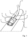
Fig. 1 : Is a perspective drawing showing a part of a hearing aid according to the invention. -
Fig. 2 and 3 : Are different perspectives of the connector as shown onfigure 1 , and with a connector plug according to the invention. -
Fig. 4 : Is a principle drawing showing a cross section of an alternative embodiment of a hearing aid according to the invention, -
Fig. 1 ,2 and 3 are all perspective drawings showing parts of a hearing aid according to the invention. In this embodiment the hearing aid is of the BTE-RIE type, where the hearing aid comprises two separate units, namely an ear plug with at least a receiver to be arranged in the ear of the user, and a hearing aid housing comprising most of the remaining electronics, such as a microphone, a battery and a processing unit, that are necessary for the functionality of the hearing aid. In this relation the connector comprises a set of electrical conductors/wiring adapted for electrical connection between the electronics, such as the receiver in the ear plug, and the remaining electronics in the hearing aid housing. The principle of the present invention, however, will be applicable to any such hearing aid, and the skilled person would easily be able to suggest many different arrangements of the electronics of the hearing aid. Furthermore the present invention may also be applicable to hearing aids where all the necessary electronics, or at least the receiver, is arranged in the hearing aid housing, and in such embodiments of the invention the connector may comprise a sound tube leading sound to the ear plug from the receiver arranged in the hearing aid housing. -
Figure 1 shows an assembled hearing aid according to the invention with thehearing aid housing 1 having anearpiece connector 3 having an ear plug with a receiver arranged at it free end (not shown) and being connected to thehearing aid housing 1 via aconnector plug 4 arranged in theconnector socket 2. Theearpiece connector 3 extends from theconnector plug body 5 through astress relieving channel 7. Theconnector plug 4 has an upperfree surface 8 being flush with the outer surface of thehearing aid housing 1 and has aconvex surface area 9 allowing a user to release theconnector plug 4 from the connector socket in thehearing aid housing 1 just by sliding e.g. a nail along theconvex surface area 9 and against therelease knob 10 having an upper surface being flush with the upperfree surface 8 of theconnector plug 4. The necessity of using a dedicated tool for releasing theconnector plug body 5 from the connector socket in the hearing aid housing is thereby avoided. -
Figure 2 and 3 shows theconnector plug 4 as shown infigure 1 but in more detail. According to this embodiment of the invention theconnector plug 4 has afront end 11 and arear end 12 from which theearpiece connector 3 extends. Adeadbolt 6 is slidably arranged in theslot 13 arranged between thefront end 11 and therear end 12 of theconnector plug 4, and the deadbolt has arelease knob 10 that extends out from thefree surface 8 of theconnector plug 4 so that it is possible for a user to slide therelease knob 10 in theknob channel 16 and there slide thedeadbolt 6 in theslot 13. - In this embodiment the deadbolt is made from a thermoplastic material by injection molding and has projections extending out from the
rear end 12 of theconnector plug 4 and at the opposite end it has integrally moldedleaf spring 14 arranged such that when theleaf spring 14 is compressed then it urges thedeadbolt 6 to slide in theslot 13 to the position shown infigure 2 and 3 , where itsprojections 19 extends out from therear end 12 of theconnector plug 4 and engages withundercuts 18 arranged in thehearing aid housing 1 as shown infigure 4 . - The front end of the connector plug is provided with a
fixed extension 15 arranged at thefront end 11 of theconnector plug 4 where it engages with theundercut 17 arranged in thehearing aid housing 1 as shown infigure 4 . Due to the fact that the deadbolt has lower andupper sloping surfaces projections 19 then it is easy for the user to attach theconnector plug 4 in the hearing aid housing just by first positioning thefixed extension 15 on thefront end 11 of theconnector plug 4 in theundercut 17 in the hearing aid housing, and thereafter pressing theconnector plug 4 into theconnector socket 2 in the hearing aid housing so that thelower sloping surface 20 urges thedeadbolt 6 to slide against the force of theleaf spring 14 and when theprojection 19 of thedeadbolt 6 aligns with theundercuts 18 in the hearing aid housing then the leaf spring urges thedeadbolt 6 to slide back so that theprojections 19 engages with theundercuts 18. - In this position the connector plug is firmly attached to the connector socket in the hearing aid housing, and any electrical contacts and/or sound tubes (not shown) are aligned to ensure proper functionality of the hearing aid. In this position, however, if the
earpiece connector 3 is exposed to a significant pulling force, then the design of theupper sloping surface 21 is made so that theprojections 19 of thedeadbolt 6 automatically disengages from theundercuts 18 in thehearing aid housing 1 before the earpiece connector is pulled out of theconnector plug 4. - Although some embodiments have been described and shown in detail, the invention is not restricted to them, but may also be embodied in other ways within the scope of the subject matter defined in the following claims. In particular, it is to be understood that other embodiments may be utilized and structural and functional modifications may be made without departing from the scope of the present invention. As mentioned above it will e.g. be apparent to the skilled person that the invention may also be used in relation to hearing aids of another type than the above mentioned BTE-RIE type, even though the advantages provided by the invention is especially relevant to the BTE-RIE type hearing aids.
- In device claims enumerating several features, several of these features can be embodied by one and the same item of hardware. The mere fact that certain measures are recited in mutually different dependent claims or described in different embodiments does not indicate that a combination of these measures cannot be used to advantage.
- It should be emphasized that the term "comprises/comprising" when used in this specification is taken to specify the presence of stated features, integers, steps or components but does not preclude the presence or addition of one or more other features, integers, steps, components or groups thereof.
Claims (13)
- A hearing aid comprising a hearing aid housing with a connector socket and an earpiece connector with a connector plug, and where the connector socket and the connector plug are configured such that the connector plug is releasably attached in the connector socket for connecting the connector to the hearing aid housing, and wherein the connector plug comprises a connector plug body having a separate deadbolt movably arranged in the connector plug body.
- A hearing aid according to claim 1, wherein the separate deadbolt is spring activated.
- A hearing aid according to claim 1 or 2, wherein the connector plug comprises a spring configured for providing a spring force.
- A hearing aid according to claim 1, 2 or 3, wherein the separate deadbolt comprises a release knob configured such that it allows that a user, by manipulating the release knob, can slide the separate deadbolt in a direction against the force of the spring.
- A hearing aid according to claim 1, wherein the connector plug has a front end and a oppositely arranged rear end and a free surface extending between the front end and the rear and facing away from the hearing aid housing when the connector plug is attached in the connector socket, and wherein the earpiece connector extends from the rear end of the connector plug.
- A hearing aid according to claim 1, wherein the separate deadbolt has one or more projections arranged such that it can be moved in the connector plug body between a retracted position where the one or more projections are retracted into the connector plug body and an extended position where the one or more projections extends from the connector plug body and into engagement with the connector socket.
- A hearing aid according to claim 1 or 5, wherein the connector socket comprises a rear undercut arranged outside the rear end of the connector plug when it is attached in the connector socket, and where the separate deadbolt has one or more projections arranged such that it can be moved in the connector plug body between a retracted position where the one or more projections are retracted into the connector plug body and an extended position where the one or more projections extends from the rear end of the connector plug body and into engagement with the rear undercut in the connector socket.
- A hearing aid according to claim 6 or 7, wherein the connector plug further comprises a spring element urging the separate deadbolt to be moved to the extended position.
- A hearing aid according to claim 6, 7 or 8, wherein the distal end of the one or more projections has sloping surfaces arranged such that the one or more projections can snap into and/or out of engagement with the rear undercut.
- A hearing aid according to anyone of claims 5-9, wherein the connector plug has a front extension projecting outwardly from the front end of the connector plug and where the connector socket has a front undercut arranged such that the front extension engages with the front undercut when the connector plug is attached in the connector socket.
- A hearing aid according to anyone of the preceding claims, wherein the separate deadbolt is arranged in a slot arranged in the connector plug body at a distance below the free surface and configured so that the separate deadbolt can slide between its extended position away from the front end of the connector plug, and its retracted position closer to the front end of the connector plug.
- A hearing aid according to anyone or more of the claims 5 - 11, wherein the separate deadbolt comprises a release knob extending through a knob channel in the connector plug body and a distance above the free surface, and where the knob channel is configured such that it allows that a user, by pushing the release knob, can slide the separate deadbolt in a direction against the force of the spring.
- A hearing aid according to any one or more of the preceding claims,
wherein the hearing aid housing is adapted for being carried behind the ear BTE of a hearing aid user, and the connector socket, the connector plug and the earpiece connector is connected to, or configured for being connected to a receiver adapted for being arranged in the ear RIE of the hearing aid user.
Priority Applications (1)
| Application Number | Priority Date | Filing Date | Title |
|---|---|---|---|
| EP23207666.1A EP4297197A3 (en) | 2017-12-22 | 2017-12-22 | Hearing aid connector |
Applications Claiming Priority (2)
| Application Number | Priority Date | Filing Date | Title |
|---|---|---|---|
| EP23207666.1A EP4297197A3 (en) | 2017-12-22 | 2017-12-22 | Hearing aid connector |
| EP17210378.0A EP3503587B1 (en) | 2017-12-22 | 2017-12-22 | Hearing aid connector |
Related Parent Applications (1)
| Application Number | Title | Priority Date | Filing Date |
|---|---|---|---|
| EP17210378.0A Division EP3503587B1 (en) | 2017-12-22 | 2017-12-22 | Hearing aid connector |
Publications (2)
| Publication Number | Publication Date |
|---|---|
| EP4297197A2 true EP4297197A2 (en) | 2023-12-27 |
| EP4297197A3 EP4297197A3 (en) | 2024-03-06 |
Family
ID=60811918
Family Applications (2)
| Application Number | Title | Priority Date | Filing Date |
|---|---|---|---|
| EP23207666.1A Pending EP4297197A3 (en) | 2017-12-22 | 2017-12-22 | Hearing aid connector |
| EP17210378.0A Active EP3503587B1 (en) | 2017-12-22 | 2017-12-22 | Hearing aid connector |
Family Applications After (1)
| Application Number | Title | Priority Date | Filing Date |
|---|---|---|---|
| EP17210378.0A Active EP3503587B1 (en) | 2017-12-22 | 2017-12-22 | Hearing aid connector |
Country Status (4)
| Country | Link |
|---|---|
| US (1) | US10715938B2 (en) |
| EP (2) | EP4297197A3 (en) |
| JP (1) | JP7092654B2 (en) |
| CN (1) | CN110035370B (en) |
Families Citing this family (6)
| Publication number | Priority date | Publication date | Assignee | Title |
|---|---|---|---|---|
| EP3817400B1 (en) * | 2019-10-28 | 2025-07-02 | GN Hearing A/S | A hearing device comprising a connector and a locking element |
| DE102020205439A1 (en) * | 2020-04-29 | 2021-11-04 | Sivantos Pte. Ltd. | Hearing aid |
| DK180901B1 (en) * | 2020-08-18 | 2022-06-21 | Gn Hearing As | Socket connector for a hearing aid |
| US12294827B2 (en) * | 2021-08-31 | 2025-05-06 | Starkey Laboratories, Inc. | Cable retention features in a custom-fitted hearing device shell |
| EP4156718A1 (en) * | 2021-09-27 | 2023-03-29 | Sonova AG | Hearing device plug connector and hearing device |
| US20250220332A1 (en) * | 2023-12-28 | 2025-07-03 | Knowles Electronics, Llc | Hearing device component with electrical cable or sound tube |
Family Cites Families (12)
| Publication number | Priority date | Publication date | Assignee | Title |
|---|---|---|---|---|
| US7142926B2 (en) * | 2002-08-30 | 2006-11-28 | Advanced Bionics Corporation | Quick connect earhook system for BTE devices |
| CN1764018A (en) * | 2004-10-22 | 2006-04-26 | 英保达股份有限公司 | A portable electronic device |
| US7684579B2 (en) * | 2006-02-06 | 2010-03-23 | Phonak Ag | Connector system for receivers of hearing devices |
| US8385573B2 (en) * | 2007-09-19 | 2013-02-26 | Starkey Laboratories, Inc. | System for hearing assistance device including receiver in the canal |
| US9295848B2 (en) * | 2008-03-28 | 2016-03-29 | Cochlear Limited | Antenna for behind-the-ear (BTE) devices |
| WO2011101041A1 (en) * | 2010-02-22 | 2011-08-25 | Siemens Medical Instruments Pte. Ltd. | Connector for a hearing instrument and hearing instrument |
| WO2012149963A1 (en) * | 2011-05-04 | 2012-11-08 | Phonak Ag | Hearing device comprising a locking mechanism for an external connector and method thereof |
| US20140119586A1 (en) * | 2012-10-25 | 2014-05-01 | Sonion A/S | Hearing aid assembly |
| DE202013000547U1 (en) * | 2013-01-18 | 2013-02-25 | Siemens Medical Instruments Pte. Ltd. | Hearing instrument housing with plug connection |
| EP3709676B1 (en) * | 2015-07-09 | 2025-04-16 | Oticon A/s | Hearing device with detachable speaker unit |
| US20170064469A1 (en) * | 2015-08-31 | 2017-03-02 | Oticon A/S | Hearing device |
| CN206452547U (en) * | 2016-12-26 | 2017-08-29 | 重庆金康特智能穿戴技术研究院有限公司 | Intelligent worn device with function of hearing aid |
-
2017
- 2017-12-22 EP EP23207666.1A patent/EP4297197A3/en active Pending
- 2017-12-22 EP EP17210378.0A patent/EP3503587B1/en active Active
-
2018
- 2018-12-12 US US16/218,221 patent/US10715938B2/en active Active
- 2018-12-19 JP JP2018237601A patent/JP7092654B2/en active Active
- 2018-12-20 CN CN201811561453.6A patent/CN110035370B/en active Active
Also Published As
| Publication number | Publication date |
|---|---|
| EP3503587C0 (en) | 2023-11-08 |
| US20190200145A1 (en) | 2019-06-27 |
| EP4297197A3 (en) | 2024-03-06 |
| US10715938B2 (en) | 2020-07-14 |
| JP2019169933A (en) | 2019-10-03 |
| CN110035370A (en) | 2019-07-19 |
| EP3503587A1 (en) | 2019-06-26 |
| JP7092654B2 (en) | 2022-06-28 |
| CN110035370B (en) | 2022-04-29 |
| EP3503587B1 (en) | 2023-11-08 |
Similar Documents
| Publication | Publication Date | Title |
|---|---|---|
| EP3503587B1 (en) | Hearing aid connector | |
| US10805743B2 (en) | Connector for a hearing instrument, and hearing instrument | |
| US7541539B2 (en) | Wall box mounting apparatus | |
| CN102158790B (en) | Hearing aid with removable attached earpiece | |
| US7110562B1 (en) | BTE/CIC auditory device and modular connector system therefor | |
| US8469734B2 (en) | Retainer system for electric cable couplers | |
| US20120195455A1 (en) | Headphone | |
| US9247360B2 (en) | Hearing instrument housing having a plug-in connection, plug and hearing instrument | |
| CN212463478U (en) | Earphone set | |
| US8290191B2 (en) | Adapter shoe and a combination of adapter shoe and hearing aid | |
| US8077895B2 (en) | Behind-the-ear hearing aid with audio shoe which can be pushed-on linearly, and appropriate mounting method | |
| US11134332B2 (en) | Acoustic receiver-in-canal ear tip | |
| EP2521378B1 (en) | Behind the ear hearing aid with receiver in the ear | |
| CN202565463U (en) | Hearing aid and conduction device used for the same | |
| CN202103845U (en) | Tool for installing and disassembling hearing aid earphone | |
| CN212259334U (en) | Hearing aid with a housing and a reversibly connectable ear piece | |
| CN104796834A (en) | BTE hearing instrument with housing and sound tube | |
| US20090022348A1 (en) | Hearing apparatus with a fastening facility for attaching an audio shoe and corresponding audio shoe | |
| US20150296314A1 (en) | Receiver/loudspeaker | |
| CN216355100U (en) | Earphone socket | |
| EP2930948A1 (en) | Hearing aid | |
| JP2022554228A (en) | Hearing device with connector and locking element | |
| EP2930949A1 (en) | A hearing aid | |
| GB2536895A (en) | Camera battery | |
| DK201470202A1 (en) | A hearing aid with receiver |
Legal Events
| Date | Code | Title | Description |
|---|---|---|---|
| PUAI | Public reference made under article 153(3) epc to a published international application that has entered the european phase |
Free format text: ORIGINAL CODE: 0009012 |
|
| STAA | Information on the status of an ep patent application or granted ep patent |
Free format text: STATUS: THE APPLICATION HAS BEEN PUBLISHED |
|
| AC | Divisional application: reference to earlier application |
Ref document number: 3503587 Country of ref document: EP Kind code of ref document: P |
|
| AK | Designated contracting states |
Kind code of ref document: A2 Designated state(s): AL AT BE BG CH CY CZ DE DK EE ES FI FR GB GR HR HU IE IS IT LI LT LU LV MC MK MT NL NO PL PT RO RS SE SI SK SM TR |
|
| REG | Reference to a national code |
Ref country code: DE Ref legal event code: R079 Free format text: PREVIOUS MAIN CLASS: H01R0013639000 Ipc: H04R0025000000 |
|
| PUAL | Search report despatched |
Free format text: ORIGINAL CODE: 0009013 |
|
| AK | Designated contracting states |
Kind code of ref document: A3 Designated state(s): AL AT BE BG CH CY CZ DE DK EE ES FI FR GB GR HR HU IE IS IT LI LT LU LV MC MK MT NL NO PL PT RO RS SE SI SK SM TR |
|
| RIC1 | Information provided on ipc code assigned before grant |
Ipc: H01R 13/639 20060101ALN20240126BHEP Ipc: H04R 25/00 20060101AFI20240126BHEP |
|
| STAA | Information on the status of an ep patent application or granted ep patent |
Free format text: STATUS: REQUEST FOR EXAMINATION WAS MADE |
|
| 17P | Request for examination filed |
Effective date: 20241127 |
|
| RBV | Designated contracting states (corrected) |
Designated state(s): AL AT BE BG CH CY CZ DE DK EE ES FI FR GB GR HR HU IE IS IT LI LT LU LV MC MK MT NL NO PL PT RO RS SE SI SK SM TR |
|
| GRAP | Despatch of communication of intention to grant a patent |
Free format text: ORIGINAL CODE: EPIDOSNIGR1 |
|
| STAA | Information on the status of an ep patent application or granted ep patent |
Free format text: STATUS: GRANT OF PATENT IS INTENDED |
|
| RIC1 | Information provided on ipc code assigned before grant |
Ipc: H04R 25/00 20060101AFI20260115BHEP Ipc: H01R 13/639 20060101ALN20260115BHEP |
|
| RIC1 | Information provided on ipc code assigned before grant |
Ipc: H04R 25/00 20060101AFI20260120BHEP Ipc: H01R 13/639 20060101ALN20260120BHEP |
|
| INTG | Intention to grant announced |
Effective date: 20260130 |