EP4297193A1 - Electrical connector assembly with flexible and rigid terminal locking features - Google Patents
Electrical connector assembly with flexible and rigid terminal locking features Download PDFInfo
- Publication number
- EP4297193A1 EP4297193A1 EP23169717.8A EP23169717A EP4297193A1 EP 4297193 A1 EP4297193 A1 EP 4297193A1 EP 23169717 A EP23169717 A EP 23169717A EP 4297193 A1 EP4297193 A1 EP 4297193A1
- Authority
- EP
- European Patent Office
- Prior art keywords
- terminal
- opening
- electrical
- cavity
- retainer
- Prior art date
- Legal status (The legal status is an assumption and is not a legal conclusion. Google has not performed a legal analysis and makes no representation as to the accuracy of the status listed.)
- Pending
Links
Images





Classifications
-
- H—ELECTRICITY
- H01—ELECTRIC ELEMENTS
- H01R—ELECTRICALLY-CONDUCTIVE CONNECTIONS; STRUCTURAL ASSOCIATIONS OF A PLURALITY OF MUTUALLY-INSULATED ELECTRICAL CONNECTING ELEMENTS; COUPLING DEVICES; CURRENT COLLECTORS
- H01R13/00—Details of coupling devices of the kinds covered by groups H01R12/70 or H01R24/00 - H01R33/00
- H01R13/40—Securing contact members in or to a base or case; Insulating of contact members
- H01R13/42—Securing in a demountable manner
- H01R13/424—Securing in base or case composed of a plurality of insulating parts having at least one resilient insulating part
-
- H—ELECTRICITY
- H01—ELECTRIC ELEMENTS
- H01R—ELECTRICALLY-CONDUCTIVE CONNECTIONS; STRUCTURAL ASSOCIATIONS OF A PLURALITY OF MUTUALLY-INSULATED ELECTRICAL CONNECTING ELEMENTS; COUPLING DEVICES; CURRENT COLLECTORS
- H01R13/00—Details of coupling devices of the kinds covered by groups H01R12/70 or H01R24/00 - H01R33/00
- H01R13/40—Securing contact members in or to a base or case; Insulating of contact members
- H01R13/42—Securing in a demountable manner
- H01R13/422—Securing in resilient one-piece base or case, e.g. by friction; One-piece base or case formed with resilient locking means
- H01R13/4223—Securing in resilient one-piece base or case, e.g. by friction; One-piece base or case formed with resilient locking means comprising integral flexible contact retaining fingers
-
- H—ELECTRICITY
- H01—ELECTRIC ELEMENTS
- H01R—ELECTRICALLY-CONDUCTIVE CONNECTIONS; STRUCTURAL ASSOCIATIONS OF A PLURALITY OF MUTUALLY-INSULATED ELECTRICAL CONNECTING ELEMENTS; COUPLING DEVICES; CURRENT COLLECTORS
- H01R13/00—Details of coupling devices of the kinds covered by groups H01R12/70 or H01R24/00 - H01R33/00
- H01R13/46—Bases; Cases
- H01R13/52—Dustproof, splashproof, drip-proof, waterproof, or flameproof cases
- H01R13/5202—Sealing means between parts of housing or between housing part and a wall, e.g. sealing rings
-
- H—ELECTRICITY
- H01—ELECTRIC ELEMENTS
- H01R—ELECTRICALLY-CONDUCTIVE CONNECTIONS; STRUCTURAL ASSOCIATIONS OF A PLURALITY OF MUTUALLY-INSULATED ELECTRICAL CONNECTING ELEMENTS; COUPLING DEVICES; CURRENT COLLECTORS
- H01R43/00—Apparatus or processes specially adapted for manufacturing, assembling, maintaining, or repairing of line connectors or current collectors or for joining electric conductors
- H01R43/20—Apparatus or processes specially adapted for manufacturing, assembling, maintaining, or repairing of line connectors or current collectors or for joining electric conductors for assembling or disassembling contact members with insulating base, case or sleeve
-
- H—ELECTRICITY
- H01—ELECTRIC ELEMENTS
- H01R—ELECTRICALLY-CONDUCTIVE CONNECTIONS; STRUCTURAL ASSOCIATIONS OF A PLURALITY OF MUTUALLY-INSULATED ELECTRICAL CONNECTING ELEMENTS; COUPLING DEVICES; CURRENT COLLECTORS
- H01R13/00—Details of coupling devices of the kinds covered by groups H01R12/70 or H01R24/00 - H01R33/00
- H01R13/46—Bases; Cases
- H01R13/502—Bases; Cases composed of different pieces
- H01R13/506—Bases; Cases composed of different pieces assembled by snap action of the parts
-
- H—ELECTRICITY
- H01—ELECTRIC ELEMENTS
- H01R—ELECTRICALLY-CONDUCTIVE CONNECTIONS; STRUCTURAL ASSOCIATIONS OF A PLURALITY OF MUTUALLY-INSULATED ELECTRICAL CONNECTING ELEMENTS; COUPLING DEVICES; CURRENT COLLECTORS
- H01R13/00—Details of coupling devices of the kinds covered by groups H01R12/70 or H01R24/00 - H01R33/00
- H01R13/46—Bases; Cases
- H01R13/52—Dustproof, splashproof, drip-proof, waterproof, or flameproof cases
- H01R13/5205—Sealing means between cable and housing, e.g. grommet
-
- H—ELECTRICITY
- H01—ELECTRIC ELEMENTS
- H01R—ELECTRICALLY-CONDUCTIVE CONNECTIONS; STRUCTURAL ASSOCIATIONS OF A PLURALITY OF MUTUALLY-INSULATED ELECTRICAL CONNECTING ELEMENTS; COUPLING DEVICES; CURRENT COLLECTORS
- H01R13/00—Details of coupling devices of the kinds covered by groups H01R12/70 or H01R24/00 - H01R33/00
- H01R13/46—Bases; Cases
- H01R13/52—Dustproof, splashproof, drip-proof, waterproof, or flameproof cases
- H01R13/5219—Sealing means between coupling parts, e.g. interfacial seal
-
- H—ELECTRICITY
- H01—ELECTRIC ELEMENTS
- H01R—ELECTRICALLY-CONDUCTIVE CONNECTIONS; STRUCTURAL ASSOCIATIONS OF A PLURALITY OF MUTUALLY-INSULATED ELECTRICAL CONNECTING ELEMENTS; COUPLING DEVICES; CURRENT COLLECTORS
- H01R2103/00—Two poles
Definitions
- This disclosure is directed to an electrical connector assembly having flexible and rigid terminal locking features.
- Connector bodies for electrical connectors used in automotive wiring harnesses have included a terminal lock nib and a flexible cantilever beam located opposite the terminal lock nib that is configured to push a terminal against a wall in the connector and into retaining engagement with the terminal lock nib.
- An example of such an electrical connector may be found in U.S. Pat. No. 9,071,016 .
- the lock nibs of connector bodies manufactured of unreinforced thermoplastics may be sheared off by forces exerted by the terminal that are less than the terminal retention force required by standards set by automotive manufacturers or organizations such as the United States Council for Automotive Research (USCAR).
- the lock nibs of connector bodies manufactured from glass fiber reinforced thermoplastics may have sufficient shear strength to meet terminal retention requirements; however, the flexible cantilever beams of these connector bodies are too stiff to provide an acceptable insertion force for inserting the terminal into the terminal cavity.
- the present invention provides alternatives to and advantages over the prior art.
- an electrical connector assembly includes an electrical terminal defining a pair of retaining ridges, a connector housing having a terminal cavity extending therethrough from a first opening to a second opening and a fixed terminal lock nib that projects inwardly into the terminal cavity from a rigid first wall to engage a first ridge of the pair of retaining ridges of the electrical terminal, and a terminal retainer inserted within the connector housing proximate the first opening and removably retained to the connector housing by a flexible retaining arm.
- the terminal retainer further includes a flexible terminal lock arm having a moveable terminal lock nib that projects inwardly into the terminal cavity from the flexible terminal lock arm to engage a second ridge of the pair of retaining ridges of the electrical terminal, thereby inhibiting removal of the electrical terminal from the terminal cavity through the second opening.
- the terminal retainer partially blocks the first opening, thereby inhibiting removal of the electrical terminal from the terminal cavity through the first opening.
- the first ridge is arranged opposite the second ridge.
- the moveable terminal lock nib is arranged opposite the fixed terminal lock nib when the terminal retainer is fully inserted within the connector housing.
- the retaining arm is a cantilevered arm and the movable terminal lock nib is arranged proximate a free end of the retaining arm.
- the assembly further includes a compliant seal surrounding the terminal cavity within the connector housing.
- the terminal retainer is further configured to retain the seal within the connector housing.
- the terminal retainer has a generally cylindrical shape.
- the terminal retainer defines a portal through which a continuity probe may be inserted to verify proper placement of the electrical terminal within the terminal cavity.
- a method of assembling an electrical connector includes the steps of:
- the steps of the method are performed in the order listed.
- the terminal retainer partially blocks the first opening, thereby inhibiting removal of the electrical terminal from the terminal cavity through the first opening.
- the method further includes the step of:
- the terminal retainer is further configured to retain the seal within the connector housing.
- an electrical connector assembly includes an electrical terminal defining a pair of retaining ridges, a connector housing having a terminal cavity extending therethrough from a first opening to a second opening and a fixed terminal lock nib that projects inwardly into the terminal cavity from a rigid first wall configured to engage a first ridge of the pair of retaining ridges and a flexible terminal lock arm having a moveable terminal lock nib that projects inwardly into the terminal cavity from the flexible terminal lock arm and configured to engage a second ridge of the pair of retaining ridges of the electrical terminal, thereby inhibiting removal of the electrical terminal from the terminal cavity through the second opening, and a terminal retainer inserted within the connector housing located proximate the first opening and removably retained to the connector housing by a flexible retaining arm.
- the terminal retainer further includes a blocking member inserted between the flexible terminal lock arm and the connector housing, thereby inhibiting disengagement of the movable terminal lock nib from the second ridge.
- the terminal retainer partially blocks the first opening, thereby inhibiting removal of the electrical terminal from the terminal cavity through the first opening.
- the terminal retainer defines a portal configured to receive a tool to disengage the movable terminal lock nib from the second ridge.
- Figs. 1 and 2 show an electrical connector assembly, e.g., a miniature coaxial connector assembly as may be used in an automotive application.
- the connector assembly includes a female connector assembly 100 and a male connector assembly 200.
- the female connector assembly 100 includes a shielded terminal 102 attached to a coaxial cable 104 that is secured within a female connector housing 106.
- the male connector assembly 200 includes a mating shielded terminal 202 attached to another coaxial cable 204 that is secured within a male connector housing 206.
- the female and male connector assemblies 100, 200 also each include a terminal retainer 108, 208 that are configured to retainer the shielded terminals 102, 202 within the connector housings 106, 206.
- the female connector assembly 100 also includes a compliant connector seal 110 that seals the interface between the connector housings 106, 206.
- the female connector assembly 100 further includes a connector position assurance (CPA) device 112 that is configured to maintain engagement of the female connector assembly 100 with the male connector assembly 200 after they are properly mated as shown in Fig. 3 .
- CPA connector position assurance
- the shielded terminal 102 defines a pair of retaining ridges 114A, 114B.
- the connector housing 106 has a terminal cavity 116 extending therethrough from a first opening 118 to a second opening 120.
- a fixed terminal lock nib 122 projects inwardly into the terminal cavity 116 from a rigid first wall 124 of the connector housing 106 to engage a first ridge 114A of the pair of retaining ridges of the shielded terminal 102.
- a terminal retainer 108 is inserted within the connector housing 106 in a location that is proximate the first opening 118.
- the terminal retainer 108 is removably retained to the connector housing 106 by a pair of flexible retaining arms 126.
- removably retained means that the terminal retainer 108 can be attached to the connector housing 106, detached from the connector housing 106, and then attached to the connector housing 106.
- the terminal retainer 108 has a generally cylindrical shape.
- the terminal retainer 108 further includes a flexible terminal lock arm 128 having a moveable terminal lock nib 130 that projects inwardly into the terminal cavity 116 from the flexible terminal lock arm 128 to engage a second ridge 114B of the pair of retaining ridges of the shielded terminal 102, thereby inhibiting removal of the shielded terminal 102 from the terminal cavity 116 through the second opening 120.
- the terminal lock arm 128 is a cantilevered arm.
- the moveable terminal lock nib 130 is arranged proximate a free end 132 of the terminal lock arm 128.
- the terminal retainer 108 includes a wall 134 that partially blocks the first opening 118.
- the wall 134 inhibits removal of the shielded terminal 102 from the terminal cavity 116 through the first opening 118.
- the first ridge 114A is arranged on the shielded terminal 102 generally opposite the second ridge 114B.
- the moveable terminal lock nib 130 is arranged opposite the fixed terminal lock nib 122 when the terminal retainer 108 is fully inserted within the connector housing 106.
- the connector seal 110 surrounds the terminal cavity 116 within the connector housing 106.
- the connector seal 110 is configured to seal the interface between the female connector assembly 100 and the male connector assembly 200 and inhibit the ingress of environmental contaminants, such as water or dust, into the terminal cavity 116 that may degrade the connection between the shielded terminals 102, 202.
- the terminal retainer 108 is further configured to retain the connector seal 110 within the connector housing 106.
- the female connector assembly 100 may also include a cable seal 138 and cable seal retainer 140 that is configured to seal the coaxial cable 104 to the connector housing 106 and inhibit the ingress of environmental contaminants into the terminal cavity 116.
- the terminal retainer 108 defines a portal 142, shown in Fig. 8A , through which a continuity probe (not shown) may be inserted to verify proper placement of the shielded terminal 102 within the terminal cavity 116.
- the shielded terminal 202 of the male connector assembly 200 defines a pair of retaining ridges 214A, 214B.
- the connector housing 206 defines a terminal cavity 216 extending from a first opening 218 to a second opening 220 and a fixed terminal lock nib 222 that projects inwardly into the terminal cavity 216 from a rigid first wall 224 to engage a first ridge 214A of the pair of retaining ridges of the shielded terminal 202.
- the connector housing 206 also defines a flexible terminal lock arm 228 having a moveable terminal lock nib 230 that projects inwardly into the terminal cavity 216 from the flexible terminal lock arm 228 to engage a second ridge 214B of the pair of retaining ridges of the shielded terminal 202.
- the moveable terminal lock nib 230 inhibits removal of the shielded terminal 202 from the terminal cavity 216 through the second opening220.
- the male connector assembly 200 also includes a terminal retainer 208 that is inserted within the connector housing 206 in a location that is proximate the first opening 218 and removably retained to the connector housing 206 by a pair of flexible retaining arms 226.
- the terminal retainer 208 includes a wall 234 that partially blocks the first opening 218.
- the wall 234 inhibits removal of the shielded terminal 202 from the terminal cavity 216 through the first opening 218.
- the first ridge 214A is arranged on the shielded terminal 202 opposite the second ridge 214B.
- the moveable terminal lock nib 230 is arranged opposite the fixed terminal lock nib 222.
- the terminal retainer 208 further includes a blocking member 244 extending generally perpendicular from the wall 234.
- the blocking member 244 is inserted between the flexible terminal lock arm 228 and the connector housing 206 and inhibits disengagement of the moveable terminal lock nib 230 from the second ridge 214B.
- the terminal retainer 208 is configured to be movable to a position where the blocking member 244 is not inserted between the flexible terminal lock arm 228 and the connector housing 206 while the terminal retainer 208 is still attached to the connector housing 206.
- the terminal retainer 208 defines a portal 242 through which a tool (not shown) may be inserted to pry the flexible terminal lock arm 228 to disengage the moveable terminal lock nib 230 from the second ridge 214B.
- Fig. 14 illustrates a method 300 of assembling the female connector assembly 100 that includes at least the steps of:
- a method 300 may also include the step of:
- 'one or more' includes a function being performed by one element, a function being performed by more than one element, e.g., in a distributed fashion, several functions being performed by one element, several functions being performed by several elements, or any combination of the above.
- first, second, etc. are, in some instances, used herein to describe various elements, these elements should not be limited by these terms. These terms are only used to distinguish one element from another.
- a first contact could be termed a second contact, and, similarly, a second contact could be termed a first contact, without departing from the scope of the various described embodiments.
- the first contact and the second contact are both contacts, but they are not the same contact.
- the term “if' is, optionally, construed to mean “when” or “upon” or “in response to determining” or “in response to detecting,” depending on the context.
- the phrase “if it is determined” or “if [a stated condition or event] is detected” is, optionally, construed to mean “upon determining” or “in response to determining” or “upon detecting [the stated condition or event]” or “in response to detecting [the stated condition or event],” depending on the context.
Landscapes
- Engineering & Computer Science (AREA)
- Manufacturing & Machinery (AREA)
- Connector Housings Or Holding Contact Members (AREA)
Abstract
Description
- This disclosure is directed to an electrical connector assembly having flexible and rigid terminal locking features.
- Connector bodies for electrical connectors used in automotive wiring harnesses have included a terminal lock nib and a flexible cantilever beam located opposite the terminal lock nib that is configured to push a terminal against a wall in the connector and into retaining engagement with the terminal lock nib. An example of such an electrical connector may be found in
U.S. Pat. No. 9,071,016 - According to an embodiment, an electrical connector assembly is provided. The electrical connector assembly includes an electrical terminal defining a pair of retaining ridges, a connector housing having a terminal cavity extending therethrough from a first opening to a second opening and a fixed terminal lock nib that projects inwardly into the terminal cavity from a rigid first wall to engage a first ridge of the pair of retaining ridges of the electrical terminal, and a terminal retainer inserted within the connector housing proximate the first opening and removably retained to the connector housing by a flexible retaining arm. The terminal retainer further includes a flexible terminal lock arm having a moveable terminal lock nib that projects inwardly into the terminal cavity from the flexible terminal lock arm to engage a second ridge of the pair of retaining ridges of the electrical terminal, thereby inhibiting removal of the electrical terminal from the terminal cavity through the second opening.
- In one or more embodiments of the electrical connector assembly according to the previous paragraph, the terminal retainer partially blocks the first opening, thereby inhibiting removal of the electrical terminal from the terminal cavity through the first opening.
- In one or more embodiments of the electrical connector assembly according to any one of the previous paragraphs, the first ridge is arranged opposite the second ridge.
- In one or more embodiments of the electrical connector assembly according to any one of the previous paragraphs, the moveable terminal lock nib is arranged opposite the fixed terminal lock nib when the terminal retainer is fully inserted within the connector housing.
- In one or more embodiments of the electrical connector assembly according to any one of the previous paragraphs, the retaining arm is a cantilevered arm and the movable terminal lock nib is arranged proximate a free end of the retaining arm.
- In one or more embodiments of the electrical connector assembly according to any one of the previous paragraphs, the assembly further includes a compliant seal surrounding the terminal cavity within the connector housing.
- In one or more embodiments of the electrical connector assembly according to any one of the previous paragraphs, the terminal retainer is further configured to retain the seal within the connector housing.
- In one or more embodiments of the electrical connector assembly according to any one of the previous paragraphs, the terminal retainer has a generally cylindrical shape.
- In one or more embodiments of the electrical connector assembly according to any one of the previous paragraphs, the terminal retainer defines a portal through which a continuity probe may be inserted to verify proper placement of the electrical terminal within the terminal cavity.
- According to an embodiment, a method of assembling an electrical connector is provided. The method includes the steps of:
- providing a connector housing having a terminal cavity extending therethrough from a first opening to a second opening and a fixed terminal lock nib that projects inwardly into the terminal cavity from a rigid first wall;
- inserting a terminal retainer within the connector housing and arranging it proximate the first opening, wherein the terminal retainer includes a flexible terminal lock arm having a moveable terminal lock nib that projects inwardly into the terminal cavity from the flexible terminal lock arm;
- removably attaching the terminal retainer to the to the connector housing via a flexible retaining arm;
- inserting an electrical terminal defining a pair of retaining ridges into the terminal cavity though the second opening; and
- engaging a first ridge of the pair of retaining ridges with the fixed terminal lock and engaging a second ridge of the pair of retaining ridges with the moveable terminal lock nib, thereby inhibiting removal of the electrical terminal from the terminal cavity through the second opening.
- In one or more embodiments of the method according to the previous paragraph, the steps of the method are performed in the order listed.
- In one or more embodiments of the method according to any one of the previous paragraphs, the terminal retainer partially blocks the first opening, thereby inhibiting removal of the electrical terminal from the terminal cavity through the first opening.
- In one or more embodiments of the method according to any one of the previous paragraphs, the method further includes the step of:
- inserting a compliant seal within the connector housing such that it surrounds the terminal cavity, wherein this step is performed prior to the step of inserting the terminal retainer within the connector housing.
- In one or more embodiments of the method according to any one of the previous paragraphs, the terminal retainer is further configured to retain the seal within the connector housing.
- According to an embodiment, an electrical connector assembly is provided. The electrical connector assembly includes an electrical terminal defining a pair of retaining ridges, a connector housing having a terminal cavity extending therethrough from a first opening to a second opening and a fixed terminal lock nib that projects inwardly into the terminal cavity from a rigid first wall configured to engage a first ridge of the pair of retaining ridges and a flexible terminal lock arm having a moveable terminal lock nib that projects inwardly into the terminal cavity from the flexible terminal lock arm and configured to engage a second ridge of the pair of retaining ridges of the electrical terminal, thereby inhibiting removal of the electrical terminal from the terminal cavity through the second opening, and a terminal retainer inserted within the connector housing located proximate the first opening and removably retained to the connector housing by a flexible retaining arm. The terminal retainer further includes a blocking member inserted between the flexible terminal lock arm and the connector housing, thereby inhibiting disengagement of the movable terminal lock nib from the second ridge.
- In one or more embodiments of the electrical connector assembly according to the previous paragraph, the terminal retainer partially blocks the first opening, thereby inhibiting removal of the electrical terminal from the terminal cavity through the first opening.
- In one or more embodiments of the electrical connector assembly according to any one of the previous paragraphs, the terminal retainer defines a portal configured to receive a tool to disengage the movable terminal lock nib from the second ridge.
- The present invention will now be described by way of example with reference to the accompanying drawings, in which:
-
Fig. 1 illustrates an exploded view of an electrical connector assembly according to some embodiments; -
Fig. 2 illustrates a cross section of the exploded view of the electrical connector assembly ofFig. 1 according to some embodiments; -
Fig. 3 illustrates a cross section side view of the electrical connector assembly ofFig. 1 according to some embodiments; -
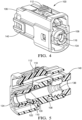
Fig. 4 illustrates a perspective view of a female connector subassembly of the electrical connector assembly ofFig. 1 according to some embodiments; -
Fig. 5 illustrates a cross section perspective view of the female connector subassembly ofFig. 4 according to some embodiments; -
Fig. 6 illustrates a cross section side view of the female connector subassembly ofFig. 4 according to some embodiments; -
Fig. 7 illustrates a cross section side view of a female connector assembly of the electrical connector assembly ofFig. 1 according to some embodiments; -
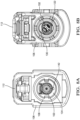
Fig. 8A illustrates a front view of the female connector assembly ofFig. 7 according to some embodiments; -
Fig. 8B illustrates a rear view of the female connector assembly ofFig. 7 according to some embodiments; -
Fig. 9A illustrates a front view of a male connector assembly of the electrical connector assembly ofFig. 1 according to some embodiments; -
Fig. 9B illustrates a rear view of the male connector assembly ofFig. 9A according to some embodiments; -
Fig. 10 illustrates a cross section side view of the male connector assembly ofFig. 9A according to some embodiments; -
Fig. 11 illustrates a perspective view of a terminal retainer of the female connector assembly ofFig. 7 according to some embodiments; -
Fig. 12 illustrates a perspective view of a terminal retainer of the male connector assembly ofFig. 9A according to some embodiments; -
Fig. 13 illustrates an alternative perspective view of the terminal retainer ofFig. 12 according to some embodiments; and -
Fig. 14 illustrates a method of assembling an electrical connector according to some embodiments. -
Figs. 1 and2 show an electrical connector assembly, e.g., a miniature coaxial connector assembly as may be used in an automotive application. The connector assembly includes afemale connector assembly 100 and amale connector assembly 200. Thefemale connector assembly 100 includes a shieldedterminal 102 attached to acoaxial cable 104 that is secured within afemale connector housing 106. Themale connector assembly 200 includes a mating shieldedterminal 202 attached to anothercoaxial cable 204 that is secured within amale connector housing 206. The female andmale connector assemblies terminal retainer terminals connector housings female connector assembly 100 also includes acompliant connector seal 110 that seals the interface between theconnector housings female connector assembly 100 further includes a connector position assurance (CPA)device 112 that is configured to maintain engagement of thefemale connector assembly 100 with themale connector assembly 200 after they are properly mated as shown inFig. 3 . - The shielded
terminal 102 defines a pair of retainingridges connector housing 106 has aterminal cavity 116 extending therethrough from afirst opening 118 to asecond opening 120. A fixedterminal lock nib 122 projects inwardly into theterminal cavity 116 from a rigidfirst wall 124 of theconnector housing 106 to engage afirst ridge 114A of the pair of retaining ridges of the shieldedterminal 102. - A
terminal retainer 108 is inserted within theconnector housing 106 in a location that is proximate thefirst opening 118. Theterminal retainer 108 is removably retained to theconnector housing 106 by a pair of flexible retainingarms 126. As used herein "removably retained" means that theterminal retainer 108 can be attached to theconnector housing 106, detached from theconnector housing 106, and then attached to theconnector housing 106. Theterminal retainer 108 has a generally cylindrical shape. Theterminal retainer 108 further includes a flexibleterminal lock arm 128 having a moveableterminal lock nib 130 that projects inwardly into theterminal cavity 116 from the flexibleterminal lock arm 128 to engage asecond ridge 114B of the pair of retaining ridges of the shieldedterminal 102, thereby inhibiting removal of the shielded terminal 102 from theterminal cavity 116 through thesecond opening 120. Theterminal lock arm 128 is a cantilevered arm. The moveableterminal lock nib 130 is arranged proximate afree end 132 of theterminal lock arm 128. - The
terminal retainer 108 includes awall 134 that partially blocks thefirst opening 118. Thewall 134 inhibits removal of the shielded terminal 102 from theterminal cavity 116 through thefirst opening 118. Thefirst ridge 114A is arranged on the shielded terminal 102 generally opposite thesecond ridge 114B. The moveableterminal lock nib 130 is arranged opposite the fixedterminal lock nib 122 when theterminal retainer 108 is fully inserted within theconnector housing 106. - The
connector seal 110 surrounds theterminal cavity 116 within theconnector housing 106. Theconnector seal 110 is configured to seal the interface between thefemale connector assembly 100 and themale connector assembly 200 and inhibit the ingress of environmental contaminants, such as water or dust, into theterminal cavity 116 that may degrade the connection between the shieldedterminals terminal retainer 108 is further configured to retain theconnector seal 110 within theconnector housing 106. As shown inFigs. 5 to 7 , thefemale connector assembly 100 may also include acable seal 138 andcable seal retainer 140 that is configured to seal thecoaxial cable 104 to theconnector housing 106 and inhibit the ingress of environmental contaminants into theterminal cavity 116. - The
terminal retainer 108 defines a portal 142, shown inFig. 8A , through which a continuity probe (not shown) may be inserted to verify proper placement of the shieldedterminal 102 within theterminal cavity 116. - As shown in
Fig. 10 , the shieldedterminal 202 of themale connector assembly 200 defines a pair of retainingridges connector housing 206 defines aterminal cavity 216 extending from afirst opening 218 to asecond opening 220 and a fixedterminal lock nib 222 that projects inwardly into theterminal cavity 216 from a rigidfirst wall 224 to engage afirst ridge 214A of the pair of retaining ridges of the shieldedterminal 202. Theconnector housing 206 also defines a flexibleterminal lock arm 228 having a moveableterminal lock nib 230 that projects inwardly into theterminal cavity 216 from the flexibleterminal lock arm 228 to engage asecond ridge 214B of the pair of retaining ridges of the shieldedterminal 202. The moveableterminal lock nib 230 inhibits removal of the shielded terminal 202 from theterminal cavity 216 through the second opening220. - The
male connector assembly 200 also includes aterminal retainer 208 that is inserted within theconnector housing 206 in a location that is proximate thefirst opening 218 and removably retained to theconnector housing 206 by a pair of flexible retainingarms 226. Theterminal retainer 208 includes awall 234 that partially blocks thefirst opening 218. Thewall 234 inhibits removal of the shielded terminal 202 from theterminal cavity 216 through thefirst opening 218. Thefirst ridge 214A is arranged on the shielded terminal 202 opposite thesecond ridge 214B. The moveableterminal lock nib 230 is arranged opposite the fixedterminal lock nib 222. Theterminal retainer 208 further includes a blockingmember 244 extending generally perpendicular from thewall 234. The blockingmember 244 is inserted between the flexibleterminal lock arm 228 and theconnector housing 206 and inhibits disengagement of the moveableterminal lock nib 230 from thesecond ridge 214B. Theterminal retainer 208 is configured to be movable to a position where the blockingmember 244 is not inserted between the flexibleterminal lock arm 228 and theconnector housing 206 while theterminal retainer 208 is still attached to theconnector housing 206. - As shown in
Figs. 9A and12 , theterminal retainer 208 defines a portal 242 through which a tool (not shown) may be inserted to pry the flexibleterminal lock arm 228 to disengage the moveableterminal lock nib 230 from thesecond ridge 214B. -
Fig. 14 illustrates amethod 300 of assembling thefemale connector assembly 100 that includes at least the steps of: -
STEP 302, providing theconnector housing 106 having theterminal cavity 116 extending through theconnector housing 106 from afirst opening 118 to asecond opening 120 and a fixedterminal lock nib 122 that projects inwardly into theterminal cavity 116 from a rigidfirst wall 124; -
STEP 306, inserting aterminal retainer 108 within theconnector housing 106 and arranging it proximate thefirst opening 118. Theterminal retainer 108 includes a flexibleterminal lock arm 128 having a moveableterminal lock nib 130 that projects inwardly into theterminal cavity 116 from the flexibleterminal lock arm 128; -
STEP 308, removably attaching theterminal retainer 108 to the to theconnector housing 106 via a pair of flexible retainingarms 126; -
STEP 310, inserting a shielded terminal 102 defining a pair of retainingridges terminal cavity 116 though thesecond opening 120; and -
STEP 312, engaging afirst ridge 114A of the pair of retaining ridges with the fixedterminal lock nib 122 and engaging asecond ridge 114B of the pair of retaining ridges with the moveableterminal lock nib 130, thereby inhibiting removal of the shielded terminal 102 from theterminal cavity 116 through thesecond opening 120. - The steps of the method are preferably performed in the order listed above.
- A
method 300 may also include the step of: -
STEP 304, inserting acompliant seal 110 within theconnector housing 106 such that it surrounds theterminal cavity 116. - While the invention has been described with reference to an exemplary embodiment(s), it will be understood by those skilled in the art that various changes may be made, and equivalents may be substituted for elements thereof without departing from the scope of the invention. In addition, many modifications may be made to adapt a particular situation or material to the teachings of the invention without departing from the essential scope thereof. Therefore, it is intended that the invention is not limited to the disclosed embodiment(s), but that the invention will include all embodiments falling within the scope of the appended claims.
- As used herein, 'one or more' includes a function being performed by one element, a function being performed by more than one element, e.g., in a distributed fashion, several functions being performed by one element, several functions being performed by several elements, or any combination of the above.
- It will also be understood that, although the terms first, second, etc. are, in some instances, used herein to describe various elements, these elements should not be limited by these terms. These terms are only used to distinguish one element from another. For example, a first contact could be termed a second contact, and, similarly, a second contact could be termed a first contact, without departing from the scope of the various described embodiments. The first contact and the second contact are both contacts, but they are not the same contact.
- The terminology used in the description of the various described embodiments herein is for the purpose of describing particular embodiments only and is not intended to be limiting. As used in the description of the various described embodiments and the appended claims, the singular forms "a", "an" and "the" are intended to include the plural forms as well, unless the context clearly indicates otherwise. It will also be understood that the term "and/or" as used herein refers to and encompasses any and all possible combinations of one or more of the associated listed items. It will be further understood that the terms "includes," "including," "comprises," and/or "comprising," when used in this specification, specify the presence of stated features, integers, steps, operations, elements, and/or components, but do not preclude the presence or addition of one or more other features, integers, steps, operations, elements, components, and/or groups thereof.
- As used herein, the term "if' is, optionally, construed to mean "when" or "upon" or "in response to determining" or "in response to detecting," depending on the context. Similarly, the phrase "if it is determined" or "if [a stated condition or event] is detected" is, optionally, construed to mean "upon determining" or "in response to determining" or "upon detecting [the stated condition or event]" or "in response to detecting [the stated condition or event]," depending on the context.
- Additionally, while terms of ordinance or orientation may be used herein these elements should not be limited by these terms. All terms of ordinance or orientation, unless stated otherwise, are used for purposes distinguishing one element from another, and do not denote any particular order, order of operations, direction or orientation unless stated otherwise.
Claims (15)
Applications Claiming Priority (2)
| Application Number | Priority Date | Filing Date | Title |
|---|---|---|---|
| US202263353959P | 2022-06-21 | 2022-06-21 | |
| US17/896,344 US12237608B2 (en) | 2022-06-21 | 2022-08-26 | Electrical connector assembly with flexible and rigid terminal locking features |
Publications (1)
| Publication Number | Publication Date |
|---|---|
| EP4297193A1 true EP4297193A1 (en) | 2023-12-27 |
Family
ID=86227013
Family Applications (1)
| Application Number | Title | Priority Date | Filing Date |
|---|---|---|---|
| EP23169717.8A Pending EP4297193A1 (en) | 2022-06-21 | 2023-04-25 | Electrical connector assembly with flexible and rigid terminal locking features |
Country Status (2)
| Country | Link |
|---|---|
| US (1) | US12237608B2 (en) |
| EP (1) | EP4297193A1 (en) |
Cited By (1)
| Publication number | Priority date | Publication date | Assignee | Title |
|---|---|---|---|---|
| EP4723390A1 (en) * | 2024-08-28 | 2026-04-08 | TE Connectivity Solutions GmbH | Electrical connector having contacts with polarizing features |
Families Citing this family (1)
| Publication number | Priority date | Publication date | Assignee | Title |
|---|---|---|---|---|
| CN120237463A (en) * | 2023-12-29 | 2025-07-01 | 泰科电子科技(苏州工业园区)有限公司 | Connector housing and connector |
Citations (7)
| Publication number | Priority date | Publication date | Assignee | Title |
|---|---|---|---|---|
| US5820411A (en) * | 1996-06-10 | 1998-10-13 | Yazaki Corporation | Connector |
| US20020076995A1 (en) * | 2000-12-20 | 2002-06-20 | Sumitomo Wiring Systems, Ltd | Connector |
| US20040192108A1 (en) * | 2003-03-25 | 2004-09-30 | Tyco Electronics Corporation | Contact stabilization by means of a primary latch reinforcement component |
| US20060292928A1 (en) * | 2005-06-23 | 2006-12-28 | Morello John R | Electrical connector |
| US20110256751A1 (en) * | 2010-04-20 | 2011-10-20 | Yazaki Corporation | Connector |
| US20140335717A1 (en) * | 2011-11-21 | 2014-11-13 | Compagnie Deutsch Gmbh | Connector assembly |
| US9071016B2 (en) | 2013-10-03 | 2015-06-30 | Delphi Technologies, Inc. | Electrical connector with a sliding flexible cantilever beam terminal retainer |
Family Cites Families (6)
| Publication number | Priority date | Publication date | Assignee | Title |
|---|---|---|---|---|
| US4973268A (en) * | 1989-10-10 | 1990-11-27 | Amp Incorporated | Multi-contact electrical connector with secondary lock |
| US5439397A (en) * | 1990-10-01 | 1995-08-08 | Yazaki Corporation | Connector |
| US5116236A (en) * | 1990-11-05 | 1992-05-26 | Molex Incorporated | Electrical connector with terminal position assurance component |
| US6036521A (en) * | 1998-03-20 | 2000-03-14 | Electrical Wiring And Connectors Application | Isolating circuits in electrical connector systems |
| US5964621A (en) * | 1998-06-25 | 1999-10-12 | The Whitaker Corporation | Connector assembly for multi-pocket header |
| US7396255B2 (en) | 2006-09-19 | 2008-07-08 | Delphi Technologies, Inc. | Electrical connector |
-
2022
- 2022-08-26 US US17/896,344 patent/US12237608B2/en active Active
-
2023
- 2023-04-25 EP EP23169717.8A patent/EP4297193A1/en active Pending
Patent Citations (7)
| Publication number | Priority date | Publication date | Assignee | Title |
|---|---|---|---|---|
| US5820411A (en) * | 1996-06-10 | 1998-10-13 | Yazaki Corporation | Connector |
| US20020076995A1 (en) * | 2000-12-20 | 2002-06-20 | Sumitomo Wiring Systems, Ltd | Connector |
| US20040192108A1 (en) * | 2003-03-25 | 2004-09-30 | Tyco Electronics Corporation | Contact stabilization by means of a primary latch reinforcement component |
| US20060292928A1 (en) * | 2005-06-23 | 2006-12-28 | Morello John R | Electrical connector |
| US20110256751A1 (en) * | 2010-04-20 | 2011-10-20 | Yazaki Corporation | Connector |
| US20140335717A1 (en) * | 2011-11-21 | 2014-11-13 | Compagnie Deutsch Gmbh | Connector assembly |
| US9071016B2 (en) | 2013-10-03 | 2015-06-30 | Delphi Technologies, Inc. | Electrical connector with a sliding flexible cantilever beam terminal retainer |
Cited By (1)
| Publication number | Priority date | Publication date | Assignee | Title |
|---|---|---|---|---|
| EP4723390A1 (en) * | 2024-08-28 | 2026-04-08 | TE Connectivity Solutions GmbH | Electrical connector having contacts with polarizing features |
Also Published As
| Publication number | Publication date |
|---|---|
| US12237608B2 (en) | 2025-02-25 |
| US20230411892A1 (en) | 2023-12-21 |
Similar Documents
| Publication | Publication Date | Title |
|---|---|---|
| KR101973894B1 (en) | Electrical connector with a terminal position assurance device | |
| US5695368A (en) | Electrical terminal with protected locking lance and a connector therefor | |
| US5145356A (en) | Electrical connector housings | |
| US20190173220A1 (en) | Electrical connector with terminal position assurance member | |
| EP2819248B1 (en) | Electrical connector with integrated moveable terminal stabilizer | |
| CN109616829B (en) | Connector with a locking member | |
| US5273456A (en) | Mate sensing connector system | |
| KR100382174B1 (en) | Electrical connector assembly having a terminal retention system | |
| EP0519577A2 (en) | A latching system | |
| EP0272804A1 (en) | Mounting means and method for rack and panel connector | |
| US5088938A (en) | Terminal locking block for electrical connectors | |
| US12237608B2 (en) | Electrical connector assembly with flexible and rigid terminal locking features | |
| US11502444B2 (en) | Electrical connector assembly having a male blade stabilizer with integrated primary lock reinforcement | |
| EP0704938A2 (en) | Reinforced connector latch | |
| EP2812951A1 (en) | Electrical connector latch | |
| EP4228100B1 (en) | Connector assembly with an unseated terminal detection feature | |
| EP1091452A1 (en) | Electrical connector with exposed molded latches | |
| CN111834788B (en) | Electrical terminal housing with terminal lock | |
| EP1701414B1 (en) | Electrical connector | |
| EP4507138A1 (en) | Right-angled connector with terminal retention features and method of assembling thereof | |
| EP4311037A1 (en) | Connector assembly with terminal position assurance and blocking feature | |
| CN117276944A (en) | Electrical connector assembly with flexible and rigid terminal locking features | |
| US20180026387A1 (en) | Cable assembly | |
| JP2557741B2 (en) | Connector lock detection method and connector using the same | |
| US9923303B2 (en) | Electrical connector with terminal centering system |
Legal Events
| Date | Code | Title | Description |
|---|---|---|---|
| PUAI | Public reference made under article 153(3) epc to a published international application that has entered the european phase |
Free format text: ORIGINAL CODE: 0009012 |
|
| STAA | Information on the status of an ep patent application or granted ep patent |
Free format text: STATUS: THE APPLICATION HAS BEEN PUBLISHED |
|
| AK | Designated contracting states |
Kind code of ref document: A1 Designated state(s): AL AT BE BG CH CY CZ DE DK EE ES FI FR GB GR HR HU IE IS IT LI LT LU LV MC ME MK MT NL NO PL PT RO RS SE SI SK SM TR |
|
| RAP1 | Party data changed (applicant data changed or rights of an application transferred) |
Owner name: APTIV TECHNOLOGIES AG |
|
| STAA | Information on the status of an ep patent application or granted ep patent |
Free format text: STATUS: REQUEST FOR EXAMINATION WAS MADE |
|
| 17P | Request for examination filed |
Effective date: 20240625 |
|
| RBV | Designated contracting states (corrected) |
Designated state(s): AL AT BE BG CH CY CZ DE DK EE ES FI FR GB GR HR HU IE IS IT LI LT LU LV MC ME MK MT NL NO PL PT RO RS SE SI SK SM TR |
|
| RAP3 | Party data changed (applicant data changed or rights of an application transferred) |
Owner name: APTIV TECHNOLOGIES AG |
|
| STAA | Information on the status of an ep patent application or granted ep patent |
Free format text: STATUS: EXAMINATION IS IN PROGRESS |
|
| 17Q | First examination report despatched |
Effective date: 20251223 |