EP4297048A1 - Duplex twisted shielded cable, and wire harness - Google Patents
Duplex twisted shielded cable, and wire harness Download PDFInfo
- Publication number
- EP4297048A1 EP4297048A1 EP23173326.2A EP23173326A EP4297048A1 EP 4297048 A1 EP4297048 A1 EP 4297048A1 EP 23173326 A EP23173326 A EP 23173326A EP 4297048 A1 EP4297048 A1 EP 4297048A1
- Authority
- EP
- European Patent Office
- Prior art keywords
- film
- shielded cable
- metal foil
- duplex
- twisted shielded
- Prior art date
- Legal status (The legal status is an assumption and is not a legal conclusion. Google has not performed a legal analysis and makes no representation as to the accuracy of the status listed.)
- Withdrawn
Links
Images





Classifications
-
- H—ELECTRICITY
- H01—ELECTRIC ELEMENTS
- H01B—CABLES; CONDUCTORS; INSULATORS; SELECTION OF MATERIALS FOR THEIR CONDUCTIVE, INSULATING OR DIELECTRIC PROPERTIES
- H01B7/00—Insulated conductors or cables characterised by their form
- H01B7/17—Protection against damage caused by external factors, e.g. sheaths or armouring
-
- H—ELECTRICITY
- H01—ELECTRIC ELEMENTS
- H01B—CABLES; CONDUCTORS; INSULATORS; SELECTION OF MATERIALS FOR THEIR CONDUCTIVE, INSULATING OR DIELECTRIC PROPERTIES
- H01B11/00—Communication cables or conductors
- H01B11/02—Cables with twisted pairs or quads
- H01B11/06—Cables with twisted pairs or quads with means for reducing effects of electromagnetic or electrostatic disturbances, e.g. screens
- H01B11/10—Screens specially adapted for reducing interference from external sources
- H01B11/1033—Screens specially adapted for reducing interference from external sources composed of a wire-braided conductor
-
- H—ELECTRICITY
- H01—ELECTRIC ELEMENTS
- H01B—CABLES; CONDUCTORS; INSULATORS; SELECTION OF MATERIALS FOR THEIR CONDUCTIVE, INSULATING OR DIELECTRIC PROPERTIES
- H01B11/00—Communication cables or conductors
- H01B11/02—Cables with twisted pairs or quads
- H01B11/06—Cables with twisted pairs or quads with means for reducing effects of electromagnetic or electrostatic disturbances, e.g. screens
- H01B11/10—Screens specially adapted for reducing interference from external sources
- H01B11/1025—Screens specially adapted for reducing interference from external sources composed of a helicoidally wound tape-conductor
-
- H—ELECTRICITY
- H01—ELECTRIC ELEMENTS
- H01B—CABLES; CONDUCTORS; INSULATORS; SELECTION OF MATERIALS FOR THEIR CONDUCTIVE, INSULATING OR DIELECTRIC PROPERTIES
- H01B11/00—Communication cables or conductors
- H01B11/02—Cables with twisted pairs or quads
- H01B11/06—Cables with twisted pairs or quads with means for reducing effects of electromagnetic or electrostatic disturbances, e.g. screens
-
- H—ELECTRICITY
- H01—ELECTRIC ELEMENTS
- H01B—CABLES; CONDUCTORS; INSULATORS; SELECTION OF MATERIALS FOR THEIR CONDUCTIVE, INSULATING OR DIELECTRIC PROPERTIES
- H01B13/00—Apparatus or processes specially adapted for manufacturing conductors or cables
- H01B13/06—Insulating conductors or cables
-
- H—ELECTRICITY
- H01—ELECTRIC ELEMENTS
- H01B—CABLES; CONDUCTORS; INSULATORS; SELECTION OF MATERIALS FOR THEIR CONDUCTIVE, INSULATING OR DIELECTRIC PROPERTIES
- H01B13/00—Apparatus or processes specially adapted for manufacturing conductors or cables
- H01B13/22—Sheathing; Armouring; Screening; Applying other protective layers
-
- H—ELECTRICITY
- H01—ELECTRIC ELEMENTS
- H01B—CABLES; CONDUCTORS; INSULATORS; SELECTION OF MATERIALS FOR THEIR CONDUCTIVE, INSULATING OR DIELECTRIC PROPERTIES
- H01B7/00—Insulated conductors or cables characterised by their form
- H01B7/0045—Cable-harnesses
-
- H—ELECTRICITY
- H01—ELECTRIC ELEMENTS
- H01B—CABLES; CONDUCTORS; INSULATORS; SELECTION OF MATERIALS FOR THEIR CONDUCTIVE, INSULATING OR DIELECTRIC PROPERTIES
- H01B7/00—Insulated conductors or cables characterised by their form
- H01B7/02—Disposition of insulation
-
- H—ELECTRICITY
- H01—ELECTRIC ELEMENTS
- H01B—CABLES; CONDUCTORS; INSULATORS; SELECTION OF MATERIALS FOR THEIR CONDUCTIVE, INSULATING OR DIELECTRIC PROPERTIES
- H01B7/00—Insulated conductors or cables characterised by their form
- H01B7/17—Protection against damage caused by external factors, e.g. sheaths or armouring
- H01B7/18—Protection against damage caused by wear, mechanical force or pressure; Sheaths; Armouring
Definitions
- the present disclosure relates to a duplex twisted shielded cable and a wire harness.
- duplex twisted shielded cable that is a duplex shielded cable for high-speed digital signal transmission for the purpose of improving characteristics of a leakage attenuation amount at the time when a differential signal is applied (see JP2017-183178A ).
- the duplex twisted shielded cable includes a twisted pair formed by twisting two insulated wires together, a metal foil shield provided around the twisted pair, a metal braid on the metal foil shield, and a sheath provided on the metal braid.
- a signal to be transmitted in such a duplex twisted shielded cable has a high frequency, and considering a skin effect and a return current, it is effective for the duplex twisted shielded cable to have a metal foil shield having a smooth surface.
- the present disclosure provides a duplex twisted shielded cable and a wire harness capable of suppressing deterioration of transmission characteristics.
- a duplex twisted shielded cable includes: two insulated wires that are twisted together, each having a conductor and an insulator covering the conductor; a film wound spirally on the two insulated wires such that parts of the film overlap each other; a metal foil shield wound spirally on the film such that parts of the metal foil shield overlap each other; a metal braid provided on an outer periphery of the metal foil shield; and a sheath provided on an outer periphery of the metal braid.
- the film and the metal foil shield are provided as a separate member.
- a wire harness includes: the duplex twisted shielded cable according to the above aspect 1 or 2; and another member adjacent to the duplex twisted shielded cable.
- FIG. 1 is a perspective view of a wire harness including a duplex twisted shielded cable according to an embodiment of the present disclosure.
- a wire harness WH includes a duplex twisted shielded cable 1 and another cable (another member) 100.
- the other cable 100 is, for example, a thick electric wire such as a power line or a thin electric wire such as another signal line, and includes a conductor 101 and an insulator 102 covering a periphery of the conductor 101.
- a resin tape RT is wound around the duplex twisted shielded cable 1 and the other cable 100, or a corrugated tube (not shown), a terminal (not shown), a connector, or the like is attached to the duplex twisted shielded cable 1 and the other cable 100.
- FIG. 2 is a perspective view illustrating the duplex twisted shielded cable 1 shown in FIG. 1
- FIG. 3 is a cross-sectional view illustrating the duplex twisted shielded cable 1 shown in FIG. 1 .
- the duplex twisted shielded cable 1 includes two insulated wires 10, a film 20, a metal foil shield 30, a metal braid 40, and a sheath 50.
- the insulated wires 10 each include a conductor 11 and an insulator 12 on the conductor 11, and are twisted so as to be helical with respect to each other.
- a soft copper wire, a silver-plated soft copper wire, a tin-plated soft copper wire, a tin-plated copper alloy wire, or the like is used as the conductor 11, a soft copper wire, a silver-plated soft copper wire, a tin-plated soft copper wire, a tin-plated copper alloy wire, or the like is used.
- the conductor 11 is implemented by a twisted wire obtained by twisting two or more (specifically, seven) wires in the embodiment, the present disclosure is not particularly limited thereto.
- the conductor 11 may be implemented by one single wire.
- a cross-sectional area of the conductor 11 is assumed to be 0.22 sq ("sq" is a unit for indicating square millimeter) or less, the present disclosure is not particularly limited thereto.
- the insulator 12 is a member covering the conductor 11.
- As the insulator 12 polyethylene (PE), polypropylene (PP), or the like is used.
- the insulator 12 has a dielectric constant of 3.0 or less.
- the film 20 is a non-conductive resin film and is made of polyethylene terephthalate (PET) resin.
- PET polyethylene terephthalate
- the metal foil shield 30 has a three-layer structure including a film layer, an adhesive layer, and a metal layer, the adhesive layer integrally bonding the film layer and the metal layer.
- the film 20 is not provided as a part of the metal foil shield 30, but is provided as a separate member.
- the film layer of the metal foil shield 30 is a non-conductive resin film, and is made of, for example, PET resin.
- the metal layer is a conductive metal layer and is made of a metal such as copper or aluminum. From the viewpoint of ensuring shielding performance, the metal layer preferably has a thickness of 8 ⁇ m or more when made of copper, and preferably has a thickness of 10 ⁇ m or more when made of aluminum.
- the metal foil shield 30 is wound on the two insulated wires 10 to overlap the parts of the film 20 to each other, so that the metal layer is on an outer side.
- the metal braid 40 is formed by weaving bundles of metal wires such as a soft copper wire, a silver-plated soft copper wire, a tin-plated soft copper wire, or a tin-plated copper alloy wire, each bundle including a plurality of the metal wires.
- the metal wire may be a plated fiber obtained by applying a metal plating on a fiber.
- the metal braid 40 may be formed by weaving a flat bundle obtained by collectively applying a plating to a plurality of metal wires.
- the sheath 50 is an insulator that covers an outer periphery of the metal braid 40.
- the sheath 50 is in a stuffing state on an outer peripheral side of the metal braid 40. That is, the sheath 50 is provided in a so-called solid state rather than in a tube form having a void inside.
- the sheath 50 is made of, for example, PE, PP, and polyvinyl chloride (PVC).
- the sheath 50 is not limited to the solid state, and may be implemented in a tube shape and disposed in a state in which a void is provided at some parts with respect to the inner metal braid 40, or any other inclusion may be separately provided in the void.
- FIG. 4 is a table illustrating duplex twisted shielded cables according to Examples 1 to 4 and Comparative Examples 1 and 2.
- a conductor was a twisted wire formed by twisting seven soft copper wires together, and had a cross-sectional area of 0.13 sq and an outer diameter of 0.48 mm.
- An insulator was made of polyolefin having a thickness of 0.37 mm, and had an outer diameter of 1.22 mm as a result of covering the conductor.
- An outer shield 1 was formed of a metal foil shield, in which a thickness of a metal layer was 10 ⁇ m and a thickness of a film layer was 6 ⁇ m, and was provided by winding the metal foil shield with respect to two insulated wires.
- An outer shield 2 was formed of a braided shield formed of a metal wire.
- a sheath was made of polyolefin.
- a film serving as a wrapping member was made of the PET resin, and a thickness thereof was 4 ⁇ m in Comparative Example 1, 6 ⁇ m in Example 1, 12 ⁇ m in Example 2, 20 ⁇ m in Example 3, and 25 ⁇ m in Example 4.
- the wrapping member is used by winding the wrapping member.
- the film serving as a wrapping member was not used.
- Comparative Example 1 since the film was actually broken due to being too thin, it was not possible to manufacture the duplex twisted shielded cable having the film.
- FIG. 5 is a graph illustrating long conversion transfer losses (LCTL) of the duplex twisted shielded cables according to Examples 1, 3, and 4 and Comparative Example 2.
- LCTL long conversion transfer losses
- FIG. 6 is a graph illustrating insertion losses of the duplex twisted shielded cables according to Examples 1, 3, and 4 and Comparative Example 2. As illustrated in FIG. 6 , regarding the insertion loss, a standard value was satisfied in all of Examples 1, 3, and 4 and Comparative Example 2. Regarding Example 2 that was not illustrated, an intermediate result between Example 1 and Example 3 was obtained similarly to the above.
- the duplex twisted shielded cables according to Examples 1 to 4 and Comparative Example 2 satisfied standard values for the characteristic impedance and the reflection loss. Accordingly, it was found that the duplex twisted shielded cables according to Examples 1 to 4 were superior to the duplex twisted shielded cable according to Comparative Example 2 in LCTL, and had good transmission characteristics. Furthermore, it was found that the duplex twisted shielded cables according to Examples 1 to 3, in which the thickness of the film was 6 ⁇ m or more and 20 ⁇ m or less, were superior to the duplex twisted shielded cable according to Example 4, in which the thickness of the film was 25 ⁇ m, in terms of LCTL, and had better transmission characteristics.
- duplex twisted shielded cables according to Examples 1 to 3 were superior to the duplex twisted shielded cable according to Example 4 in the characteristic impedance at the time of cable bending.
- FIG. 7A is a cross-sectional view illustrating the duplex twisted shielded cables at the time of bending according to Examples 1 to 3.
- FIG. 7B is a cross-sectional view illustrating the duplex twisted shielded cable at the time of bending according to Example 4.
- the duplex twisted shielded cable shown in FIG. 7A has a film of 20 ⁇ m or less. Therefore, the film is relatively thin, and is wound around the two insulated wires in a state where an ellipticity in value is small.
- the duplex twisted shielded cable is bent in an elliptical short-axis direction, the duplex twisted shielded cable is flattened, and a distance between the metal foil shield and the two insulated wires is reduced by D1.
- the duplex twisted shielded cable shown in FIG. 7B has a film thickness of 25 ⁇ m. Therefore, the film is relatively thick, and is wound around the two insulated wires in a state where an ellipticity in value is large.
- the duplex twisted shielded cable is bent in the elliptical short-axis direction, the duplex twisted shielded cable is flattened, and a distance between the metal foil shield and the two insulated wires is reduced by D2 (> D1).
- FIG. 8 is a graph illustrating a characteristic impedance of the duplex twisted shielded cable at the time of bending.
- broken lines indicate standard values.
- the characteristic impedance decreases to the vicinity of a characteristic impedance standard value (95 S2).
- the characteristic impedance does not fall outside the standard value, but when the amount of change in the distance between the metal foil shield and the two insulated wires increases, the characteristic impedance may fall outside the standard value.
- FIG. 9 is a table illustrating characteristic impedances of the duplex twisted shielded cables at the time of bending.
- a result of measuring the characteristic impedance of the duplex twisted shielded cable in a straight state is shown, with the number of samples being five.
- a result of measuring the characteristic impedance when bending by 180° is performed with a cable outer diameter as the diameter is shown, with the number of samples being five.
- a decrease width indicates a difference between the results.
- Numerical values in parentheses indicate a minimum value and a maximum value, and a numerical value outside the parentheses indicate a median value. Further, the bending by 180° of own diameter is assumed to be a worst condition in mounting on a vehicle.
- the decrease width is about 6 ⁇ , and the characteristic impedance does not fall below 95 S2, which is the standard value, even after bending.
- the decrease width reaches 9.8 Q, and the characteristic impedance falls below the standard value of 95 ⁇ after bending. Therefore, regarding the characteristic impedance at the time of cable bending, it was found that the duplex twisted shielded cables according to Examples 1 to 3 were superior to the duplex twisted shielded cable according to Example 4.
- the duplex twisted shielded cable 1 of the embodiment includes the film 20 wound spirally on the two insulated wires 10 to overlap the parts of the film 20 to each other and the metal foil shield 30 wound spirally on the film 20 to overlap the parts of the metal foil shield 30 to each other, and the film 20 and the metal foil shield 30 are provided as a separate member.
- the film 20 and the metal foil shield 30, which are provided as a separate member are each wound spirally to overlap the parts of the film 20 and the parts of the metal foil shield 30, respectively, it is possible to wind the film 20 and the metal foil shield 30 without causing wrinkles even in a space S (see FIG.
- the metal foil shield 30 is wound in a state where the film 20 exists at an inner side, the metal foil shield 30 is wound in a state where the space S between the two insulated wires 10 is filled with the film 20. Accordingly, the occurrence of wrinkles in the metal foil shield 30 is further suppressed, and the position of the metal foil shield 30 with respect to the two insulated wires 10 can be easily stabilized. Accordingly, it is possible to provide the duplex twisted shielded cable 1 capable of suppressing deterioration of the transmission characteristics.
- the thickness of the film 20 is a range of 6 ⁇ m or more and 20 ⁇ m or less, it is possible to easily prevent breakage at the time of manufacturing the duplex twisted shielded cable 1 and to easily satisfy a standard value (of June in 2022).
- the wire harness WH of the embodiment it is possible to provide the wire harness WH capable of suppressing deterioration of transmission characteristics.
- the metal foil shield 30 is disposed such that the metal layer faces an outer side in the duplex twisted shielded cable 1 in the above-described embodiments, the present disclosure is not limited thereto, and the metal foil shield 30 may face an inner side.
- the metal braid 40 is attached to a shielded connector.
- the attachment target may not be a shielded connector.
- a duplex twisted shielded cable (1) includes: two insulated wires (10) that are twisted together, each having a conductor (11) and an insulator (12) covering the conductor (11); a film (20) wound spirally on the two insulated wires (10) such that parts of the film (20) overlap each other; a metal foil shield (30) wound spirally on the film (20) such that parts of the metal foil shield (30) overlap each other; a metal braid (40) provided on an outer periphery of the metal foil shield (30); and a sheath (50) provided on an outer periphery of the metal braid (40).
- the film (20) and the metal foil shield (30) are provided as a separate member.
- the film (20) may have a thickness of 6 ⁇ m or more and 20 ⁇ m or less.
- a wire harness may include: the duplex twisted shielded cable (1) according to the aspect 1 or 2; and another member (100) adjacent to the duplex twisted shielded cable (1).
Landscapes
- Physics & Mathematics (AREA)
- Electromagnetism (AREA)
- Engineering & Computer Science (AREA)
- Manufacturing & Machinery (AREA)
- Insulated Conductors (AREA)
- Communication Cables (AREA)
Abstract
Description
- The present disclosure relates to a duplex twisted shielded cable and a wire harness.
- In the related art, there has been proposed a duplex twisted shielded cable that is a duplex shielded cable for high-speed digital signal transmission for the purpose of improving characteristics of a leakage attenuation amount at the time when a differential signal is applied (see
JP2017-183178A - The duplex twisted shielded cable includes a twisted pair formed by twisting two insulated wires together, a metal foil shield provided around the twisted pair, a metal braid on the metal foil shield, and a sheath provided on the metal braid.
- A signal to be transmitted in such a duplex twisted shielded cable has a high frequency, and considering a skin effect and a return current, it is effective for the duplex twisted shielded cable to have a metal foil shield having a smooth surface.
- However, in the duplex twisted shielded cable disclosed in
JP2017-183178A - The present disclosure provides a duplex twisted shielded cable and a wire harness capable of suppressing deterioration of transmission characteristics.
- According to an illustrative aspect of the present disclosure, a duplex twisted shielded cable includes: two insulated wires that are twisted together, each having a conductor and an insulator covering the conductor; a film wound spirally on the two insulated wires such that parts of the film overlap each other; a metal foil shield wound spirally on the film such that parts of the metal foil shield overlap each other; a metal braid provided on an outer periphery of the metal foil shield; and a sheath provided on an outer periphery of the metal braid. The film and the metal foil shield are provided as a separate member.
- According to another illustrative aspect of the present disclosure, a wire harness includes: the duplex twisted shielded cable according to the
above aspect -
-
FIG. 1 is a perspective view of a wire harness including a duplex twisted shielded cable according to an embodiment of the present disclosure; -
FIG. 2 is a perspective view illustrating the duplex twisted shielded cable shown inFIG. 1 ; -
FIG. 3 is a cross-sectional view illustrating the duplex twisted shielded cable shown inFIG. 1 ; -
FIG. 4 is a table illustrating duplex twisted shielded cables according to Examples 1 to 4 and Comparative Examples 1 and 2; -
FIG. 5 is a graph illustrating LCTL of the duplex twisted shielded cables according to Examples 1, 3, and 4 and Comparative Example 2; -
FIG. 6 is a graph illustrating insertion losses of the duplex twisted shielded cables according to Examples 1, 3, and 4 and Comparative Example 2; -
FIG. 7A is a cross-sectional view illustrating the duplex twisted shielded cables at the time of bending according to Examples 1 to 3; -
FIG. 7B is a cross-sectional view illustrating the duplex twisted shielded cable at the time of bending according to Example 4; -
FIG. 8 is a graph illustrating a characteristic impedance of the duplex twisted shielded cable at the time of bending; and -
FIG. 9 is a table illustrating characteristic impedances of the duplex twisted shielded cables at the time of bending. - Hereinafter, the present disclosure will be described with reference to preferred embodiments. It should be noted that the present disclosure is not limited to the following embodiments, and modifications can be appropriately made without departing from the gist of the present disclosure. In addition, in the embodiments described below, although there are portions in which illustration and description of a part of the configuration are omitted, it is needless to say that a publicly known or well-known technique is appropriately applied to the details of the omitted technique within a range in which no contradiction with the contents described below occurs.
-
FIG. 1 is a perspective view of a wire harness including a duplex twisted shielded cable according to an embodiment of the present disclosure. As illustrated inFIG. 1 , a wire harness WH includes a duplex twisted shieldedcable 1 and another cable (another member) 100. - The
other cable 100 is, for example, a thick electric wire such as a power line or a thin electric wire such as another signal line, and includes aconductor 101 and aninsulator 102 covering a periphery of theconductor 101. A resin tape RT is wound around the duplex twisted shieldedcable 1 and theother cable 100, or a corrugated tube (not shown), a terminal (not shown), a connector, or the like is attached to the duplex twisted shieldedcable 1 and theother cable 100. -
FIG. 2 is a perspective view illustrating the duplex twisted shieldedcable 1 shown inFIG. 1 , andFIG. 3 is a cross-sectional view illustrating the duplex twisted shieldedcable 1 shown inFIG. 1 . As illustrated inFIGS. 2 and3 , the duplex twisted shieldedcable 1 includes two insulatedwires 10, afilm 20, ametal foil shield 30, ametal braid 40, and asheath 50. - The
insulated wires 10 each include aconductor 11 and aninsulator 12 on theconductor 11, and are twisted so as to be helical with respect to each other. As theconductor 11, a soft copper wire, a silver-plated soft copper wire, a tin-plated soft copper wire, a tin-plated copper alloy wire, or the like is used. Although theconductor 11 is implemented by a twisted wire obtained by twisting two or more (specifically, seven) wires in the embodiment, the present disclosure is not particularly limited thereto. Theconductor 11 may be implemented by one single wire. Further, although a cross-sectional area of theconductor 11 is assumed to be 0.22 sq ("sq" is a unit for indicating square millimeter) or less, the present disclosure is not particularly limited thereto. - The
insulator 12 is a member covering theconductor 11. As theinsulator 12, polyethylene (PE), polypropylene (PP), or the like is used. Theinsulator 12 has a dielectric constant of 3.0 or less. - The
film 20 is a non-conductive resin film and is made of polyethylene terephthalate (PET) resin. Thefilm 20 is wound spirally on the two insulatedwires 10 and parts of thefilm 20 overlap each other. - The
metal foil shield 30 has a three-layer structure including a film layer, an adhesive layer, and a metal layer, the adhesive layer integrally bonding the film layer and the metal layer. Themetal foil shield 30 wound spirally on thefilm 20 and parts of themetal foil shield 30 overlap each other. Thefilm 20 is not provided as a part of themetal foil shield 30, but is provided as a separate member. - The film layer of the
metal foil shield 30 is a non-conductive resin film, and is made of, for example, PET resin. The metal layer is a conductive metal layer and is made of a metal such as copper or aluminum. From the viewpoint of ensuring shielding performance, the metal layer preferably has a thickness of 8 µm or more when made of copper, and preferably has a thickness of 10 µm or more when made of aluminum. Themetal foil shield 30 is wound on the two insulatedwires 10 to overlap the parts of thefilm 20 to each other, so that the metal layer is on an outer side. - The
metal braid 40 is formed by weaving bundles of metal wires such as a soft copper wire, a silver-plated soft copper wire, a tin-plated soft copper wire, or a tin-plated copper alloy wire, each bundle including a plurality of the metal wires. The metal wire may be a plated fiber obtained by applying a metal plating on a fiber. Further, themetal braid 40 may be formed by weaving a flat bundle obtained by collectively applying a plating to a plurality of metal wires. - The
sheath 50 is an insulator that covers an outer periphery of themetal braid 40. Thesheath 50 is in a stuffing state on an outer peripheral side of themetal braid 40. That is, thesheath 50 is provided in a so-called solid state rather than in a tube form having a void inside. By solid extrusion with respect to a component formed of theinsulated wires 10, thefilm 20, themetal foil shield 30, and themetal braid 40, thesheath 50 is provided around theinsulated wires 10, thefilm 20, themetal foil shield 30, and themetal braid 40. Thesheath 50 is made of, for example, PE, PP, and polyvinyl chloride (PVC). Thesheath 50 is not limited to the solid state, and may be implemented in a tube shape and disposed in a state in which a void is provided at some parts with respect to theinner metal braid 40, or any other inclusion may be separately provided in the void. - Next, examples and comparative examples of the duplex twisted shielded
cable 1 according to the embodiment will be described.FIG. 4 is a table illustrating duplex twisted shielded cables according to Examples 1 to 4 and Comparative Examples 1 and 2. In the duplex twisted shielded cables according to Examples 1 to 4 and Comparative Examples 1 and 2, a conductor was a twisted wire formed by twisting seven soft copper wires together, and had a cross-sectional area of 0.13 sq and an outer diameter of 0.48 mm. An insulator was made of polyolefin having a thickness of 0.37 mm, and had an outer diameter of 1.22 mm as a result of covering the conductor. - An
outer shield 1 was formed of a metal foil shield, in which a thickness of a metal layer was 10 µm and a thickness of a film layer was 6 µm, and was provided by winding the metal foil shield with respect to two insulated wires. Anouter shield 2 was formed of a braided shield formed of a metal wire. A sheath was made of polyolefin. With the above configuration, the duplex twisted shielded cables according to Examples 1 to 4 and Comparative Examples 1 and 2 had a finished outer diameter of 3.8 mm. - A film serving as a wrapping member was made of the PET resin, and a thickness thereof was 4 µm in Comparative Example 1, 6 µm in Example 1, 12 µm in Example 2, 20 µm in Example 3, and 25 µm in Example 4. The wrapping member is used by winding the wrapping member. In Comparative Example 2, the film serving as a wrapping member was not used.
- In Comparative Example 1, since the film was actually broken due to being too thin, it was not possible to manufacture the duplex twisted shielded cable having the film.
-
FIG. 5 is a graph illustrating long conversion transfer losses (LCTL) of the duplex twisted shielded cables according to Examples 1, 3, and 4 and Comparative Example 2. As illustrated inFIG. 5 , regarding Examples 1 and 3, a result was shown that a standard value was satisfied in the entire frequency range from 0.01 GHz to 0.5 GHz. Regarding Example 4, the standard value was not satisfied in some frequency ranges but was satisfied in the remaining majority of frequency ranges, and it was found that Example 4 was usable depending on a frequency band of a signal to be received and transmitted. In contrast, regarding Comparative Example 2, a result was shown that the standard value was not satisfied in a range from less than 0.05 GHz to less than about 0.4 GHz. This is because the duplex twisted shielded cable according to Comparative Example 2 did not have a film and a position of the metal foil shield was unstable. Although Example 2 was not illustrated, an intermediate result between those of Example 1 and Example 3 was confirmed. -
FIG. 6 is a graph illustrating insertion losses of the duplex twisted shielded cables according to Examples 1, 3, and 4 and Comparative Example 2. As illustrated inFIG. 6 , regarding the insertion loss, a standard value was satisfied in all of Examples 1, 3, and 4 and Comparative Example 2. Regarding Example 2 that was not illustrated, an intermediate result between Example 1 and Example 3 was obtained similarly to the above. - Further, although not illustrated, the duplex twisted shielded cables according to Examples 1 to 4 and Comparative Example 2 satisfied standard values for the characteristic impedance and the reflection loss. Accordingly, it was found that the duplex twisted shielded cables according to Examples 1 to 4 were superior to the duplex twisted shielded cable according to Comparative Example 2 in LCTL, and had good transmission characteristics. Furthermore, it was found that the duplex twisted shielded cables according to Examples 1 to 3, in which the thickness of the film was 6 µm or more and 20 µm or less, were superior to the duplex twisted shielded cable according to Example 4, in which the thickness of the film was 25 µm, in terms of LCTL, and had better transmission characteristics.
- In addition, it was found that the duplex twisted shielded cables according to Examples 1 to 3 were superior to the duplex twisted shielded cable according to Example 4 in the characteristic impedance at the time of cable bending.
-
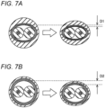
FIG. 7A is a cross-sectional view illustrating the duplex twisted shielded cables at the time of bending according to Examples 1 to 3.FIG. 7B is a cross-sectional view illustrating the duplex twisted shielded cable at the time of bending according to Example 4. - The duplex twisted shielded cable shown in
FIG. 7A has a film of 20 µm or less. Therefore, the film is relatively thin, and is wound around the two insulated wires in a state where an ellipticity in value is small. When such a duplex twisted shielded cable is bent in an elliptical short-axis direction, the duplex twisted shielded cable is flattened, and a distance between the metal foil shield and the two insulated wires is reduced by D1. - On the other hand, the duplex twisted shielded cable shown in
FIG. 7B has a film thickness of 25 µm. Therefore, the film is relatively thick, and is wound around the two insulated wires in a state where an ellipticity in value is large. When such a duplex twisted shielded cable is bent in the elliptical short-axis direction, the duplex twisted shielded cable is flattened, and a distance between the metal foil shield and the two insulated wires is reduced by D2 (> D1). - As described above, in the duplex twisted shielded cable having a thick film, a change in the distance between the metal foil shield and the two insulated wires is large at the time of bending, and the transmission characteristics are easily deteriorated.
-
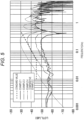
FIG. 8 is a graph illustrating a characteristic impedance of the duplex twisted shielded cable at the time of bending. InFIG. 8 , broken lines indicate standard values. As illustrated inFIG. 8 , in a case where a bent portion is present, the distance between the metal foil shield and the two insulated wires changes, and therefore, as shown at a time-point of 9 ns, the characteristic impedance decreases to the vicinity of a characteristic impedance standard value (95 S2). Here, in the example illustrated inFIG. 8 , the characteristic impedance does not fall outside the standard value, but when the amount of change in the distance between the metal foil shield and the two insulated wires increases, the characteristic impedance may fall outside the standard value. -
FIG. 9 is a table illustrating characteristic impedances of the duplex twisted shielded cables at the time of bending. First, in the table shown inFIG. 9 , in a column of initial stage, a result of measuring the characteristic impedance of the duplex twisted shielded cable in a straight state is shown, with the number of samples being five. Similarly, in a column of after bending (by 180° of own diameter), a result of measuring the characteristic impedance when bending by 180° is performed with a cable outer diameter as the diameter is shown, with the number of samples being five. A decrease width indicates a difference between the results. Numerical values in parentheses indicate a minimum value and a maximum value, and a numerical value outside the parentheses indicate a median value. Further, the bending by 180° of own diameter is assumed to be a worst condition in mounting on a vehicle. - As illustrated in
FIG. 9 , regarding Examples 1 to 3, the decrease width is about 6Ω, and the characteristic impedance does not fall below 95 S2, which is the standard value, even after bending. On the other hand, in Example 4, the decrease width reaches 9.8 Q, and the characteristic impedance falls below the standard value of 95 Ω after bending. Therefore, regarding the characteristic impedance at the time of cable bending, it was found that the duplex twisted shielded cables according to Examples 1 to 3 were superior to the duplex twisted shielded cable according to Example 4. - In this way, the duplex twisted shielded
cable 1 of the embodiment includes thefilm 20 wound spirally on the twoinsulated wires 10 to overlap the parts of thefilm 20 to each other and themetal foil shield 30 wound spirally on thefilm 20 to overlap the parts of themetal foil shield 30 to each other, and thefilm 20 and themetal foil shield 30 are provided as a separate member. As described above, since thefilm 20 and themetal foil shield 30, which are provided as a separate member, are each wound spirally to overlap the parts of thefilm 20 and the parts of themetal foil shield 30, respectively, it is possible to wind thefilm 20 and themetal foil shield 30 without causing wrinkles even in a space S (seeFIG. 3 ) between the twoinsulated wires 10 because of a characteristic of a spiral winding and overlapping of the parts. In addition, since themetal foil shield 30 is wound in a state where thefilm 20 exists at an inner side, themetal foil shield 30 is wound in a state where the space S between the twoinsulated wires 10 is filled with thefilm 20. Accordingly, the occurrence of wrinkles in themetal foil shield 30 is further suppressed, and the position of themetal foil shield 30 with respect to the twoinsulated wires 10 can be easily stabilized. Accordingly, it is possible to provide the duplex twisted shieldedcable 1 capable of suppressing deterioration of the transmission characteristics. - In addition, since the thickness of the
film 20 is a range of 6 µm or more and 20 µm or less, it is possible to easily prevent breakage at the time of manufacturing the duplex twisted shieldedcable 1 and to easily satisfy a standard value (of June in 2022). - In addition, according to the wire harness WH of the embodiment, it is possible to provide the wire harness WH capable of suppressing deterioration of transmission characteristics.
- Although the present disclosure has been described above based on the embodiments, the present disclosure is not limited to the above embodiments. Modifications may be made without departing from the gist of the present disclosure and publicly known or well-known techniques may be appropriately combined.
- For example, although the
metal foil shield 30 is disposed such that the metal layer faces an outer side in the duplex twisted shieldedcable 1 in the above-described embodiments, the present disclosure is not limited thereto, and themetal foil shield 30 may face an inner side. - In addition, in the duplex twisted shielded
cable 1 according to the embodiment, it is assumed that themetal braid 40 is attached to a shielded connector. Alternatively, the attachment target may not be a shielded connector. - According to an
aspect 1 of the present disclosure, a duplex twisted shielded cable (1) includes: two insulated wires (10) that are twisted together, each having a conductor (11) and an insulator (12) covering the conductor (11); a film (20) wound spirally on the two insulated wires (10) such that parts of the film (20) overlap each other; a metal foil shield (30) wound spirally on the film (20) such that parts of the metal foil shield (30) overlap each other; a metal braid (40) provided on an outer periphery of the metal foil shield (30); and a sheath (50) provided on an outer periphery of the metal braid (40). The film (20) and the metal foil shield (30) are provided as a separate member. - According to an
aspect 2 of the present disclosure, the film (20) may have a thickness of 6 µm or more and 20 µm or less. - According to an
aspect 3 of the present disclosure, a wire harness (WH) may include: the duplex twisted shielded cable (1) according to theaspect - According to the present disclosure, it is possible to provide a duplex twisted shielded cable and a wire harness capable of suppressing deterioration of transmission characteristics.
Claims (3)
- A duplex twisted shielded cable (1) comprising:two insulated wires (10) that are twisted together, each having a conductor (11) and an insulator (12) covering the conductor (11);a film (20) wound spirally on the two insulated wires (10) such that parts of the film (20) overlap each other;a metal foil shield (30) wound spirally on the film (20) such that parts of the metal foil shield (30) overlap each other;a metal braid (40) provided on an outer periphery of the metal foil shield (30); anda sheath (50) provided on an outer periphery of the metal braid (40), whereinthe film (20) and the metal foil shield (30) are provided as a separate member.
- The duplex twisted shielded cable (1) according to claim 1, wherein the film (20) has a thickness of 6 µm or more and 20 µm or less.
- A wire harness (WH) comprising:the duplex twisted shielded cable (1) according to claim 1 or 2; andanother member (100) adjacent to the duplex twisted shielded cable (1).
Applications Claiming Priority (1)
| Application Number | Priority Date | Filing Date | Title |
|---|---|---|---|
| JP2022098652A JP7562602B2 (en) | 2022-06-20 | 2022-06-20 | 2-core twisted shielded cable and wire harness |
Publications (1)
| Publication Number | Publication Date |
|---|---|
| EP4297048A1 true EP4297048A1 (en) | 2023-12-27 |
Family
ID=86382896
Family Applications (1)
| Application Number | Title | Priority Date | Filing Date |
|---|---|---|---|
| EP23173326.2A Withdrawn EP4297048A1 (en) | 2022-06-20 | 2023-05-15 | Duplex twisted shielded cable, and wire harness |
Country Status (4)
| Country | Link |
|---|---|
| US (1) | US20230411044A1 (en) |
| EP (1) | EP4297048A1 (en) |
| JP (1) | JP7562602B2 (en) |
| CN (1) | CN117275809A (en) |
Citations (5)
| Publication number | Priority date | Publication date | Assignee | Title |
|---|---|---|---|---|
| US20110139485A1 (en) * | 2009-12-10 | 2011-06-16 | Sumitomo Electric Industries, Ltd. | Multi-core cable |
| JP2017183178A (en) | 2016-03-31 | 2017-10-05 | 株式会社オートネットワーク技術研究所 | Shield wire for communication |
| WO2019058437A1 (en) * | 2017-09-19 | 2019-03-28 | 株式会社オートネットワーク技術研究所 | Shielded communication cable |
| US20190096547A1 (en) * | 2017-09-25 | 2019-03-28 | Yazaki Corporation | Differential transmission cable and wire harness |
| EP3882931A1 (en) * | 2020-03-18 | 2021-09-22 | Gebauer & Griller Kabelwerke Gesellschaft m.b.H. | Cable |
Family Cites Families (1)
| Publication number | Priority date | Publication date | Assignee | Title |
|---|---|---|---|---|
| WO2022138900A1 (en) | 2020-12-24 | 2022-06-30 | 昭和電線ケーブルシステム株式会社 | Communication cable and manufacturing method therefor |
-
2022
- 2022-06-20 JP JP2022098652A patent/JP7562602B2/en active Active
-
2023
- 2023-05-15 CN CN202310543060.7A patent/CN117275809A/en active Pending
- 2023-05-15 EP EP23173326.2A patent/EP4297048A1/en not_active Withdrawn
- 2023-05-15 US US18/317,867 patent/US20230411044A1/en active Pending
Patent Citations (5)
| Publication number | Priority date | Publication date | Assignee | Title |
|---|---|---|---|---|
| US20110139485A1 (en) * | 2009-12-10 | 2011-06-16 | Sumitomo Electric Industries, Ltd. | Multi-core cable |
| JP2017183178A (en) | 2016-03-31 | 2017-10-05 | 株式会社オートネットワーク技術研究所 | Shield wire for communication |
| WO2019058437A1 (en) * | 2017-09-19 | 2019-03-28 | 株式会社オートネットワーク技術研究所 | Shielded communication cable |
| US20190096547A1 (en) * | 2017-09-25 | 2019-03-28 | Yazaki Corporation | Differential transmission cable and wire harness |
| EP3882931A1 (en) * | 2020-03-18 | 2021-09-22 | Gebauer & Griller Kabelwerke Gesellschaft m.b.H. | Cable |
Also Published As
| Publication number | Publication date |
|---|---|
| JP7562602B2 (en) | 2024-10-07 |
| JP2024000098A (en) | 2024-01-05 |
| US20230411044A1 (en) | 2023-12-21 |
| CN117275809A (en) | 2023-12-22 |
Similar Documents
| Publication | Publication Date | Title |
|---|---|---|
| KR102548464B1 (en) | Shield cable | |
| US20140299349A1 (en) | High-speed signal transmission cable | |
| US20110247856A1 (en) | Shielded cable | |
| US10818415B2 (en) | Shielded communication cable | |
| US20180268965A1 (en) | Data cable for high speed data transmissions and method of manufacturing the data cable | |
| US20190096546A1 (en) | 2-core shielded cable and wire harness | |
| US11798710B2 (en) | Cable having a pair of inner conductors and an inner insulating layer extrusion molded around the pair of inner conductors | |
| US20220215987A1 (en) | Cable | |
| US20210012928A1 (en) | Multicore cable | |
| JP7339042B2 (en) | Differential transmission cable and wire harness | |
| JP7476767B2 (en) | Composite Cable | |
| US20240079161A1 (en) | Two-core twisted shielded cable and wire harness | |
| EP3594970B1 (en) | Routing structure of two-core parallel shielded electric wire | |
| US20230411044A1 (en) | Duplex twisted shielded cable, and wire harness | |
| KR20220164689A (en) | coax | |
| EP3905281B1 (en) | Communication cable and wire harness | |
| US12512235B2 (en) | Duplex twisted shielded cable, and wire harness | |
| CN217544182U (en) | Cable with a flexible connection | |
| JP2024148544A (en) | Composite Cable | |
| EP4730365A1 (en) | Highly shielded ethernet cable for vehicle, and manufacturing method thereof | |
| JP2017139189A (en) | Differential signal transmission cable |
Legal Events
| Date | Code | Title | Description |
|---|---|---|---|
| PUAI | Public reference made under article 153(3) epc to a published international application that has entered the european phase |
Free format text: ORIGINAL CODE: 0009012 |
|
| STAA | Information on the status of an ep patent application or granted ep patent |
Free format text: STATUS: REQUEST FOR EXAMINATION WAS MADE |
|
| 17P | Request for examination filed |
Effective date: 20230515 |
|
| AK | Designated contracting states |
Kind code of ref document: A1 Designated state(s): AL AT BE BG CH CY CZ DE DK EE ES FI FR GB GR HR HU IE IS IT LI LT LU LV MC ME MK MT NL NO PL PT RO RS SE SI SK SM TR |
|
| STAA | Information on the status of an ep patent application or granted ep patent |
Free format text: STATUS: EXAMINATION IS IN PROGRESS |
|
| 17Q | First examination report despatched |
Effective date: 20240229 |
|
| STAA | Information on the status of an ep patent application or granted ep patent |
Free format text: STATUS: THE APPLICATION IS DEEMED TO BE WITHDRAWN |
|
| 18D | Application deemed to be withdrawn |
Effective date: 20250812 |