EP4296990A1 - Assisted driving method, stop recess, chip, electronic device, and storage medium - Google Patents
Assisted driving method, stop recess, chip, electronic device, and storage medium Download PDFInfo
- Publication number
- EP4296990A1 EP4296990A1 EP21927165.7A EP21927165A EP4296990A1 EP 4296990 A1 EP4296990 A1 EP 4296990A1 EP 21927165 A EP21927165 A EP 21927165A EP 4296990 A1 EP4296990 A1 EP 4296990A1
- Authority
- EP
- European Patent Office
- Prior art keywords
- vehicle
- flying apparatus
- preset
- flying
- target distance
- Prior art date
- Legal status (The legal status is an assumption and is not a legal conclusion. Google has not performed a legal analysis and makes no representation as to the accuracy of the status listed.)
- Granted
Links
Images



Classifications
-
- G—PHYSICS
- G08—SIGNALLING
- G08G—TRAFFIC CONTROL SYSTEMS
- G08G1/00—Traffic control systems for road vehicles
- G08G1/01—Detecting movement of traffic to be counted or controlled
- G08G1/0104—Measuring and analyzing of parameters relative to traffic conditions
- G08G1/0108—Measuring and analyzing of parameters relative to traffic conditions based on the source of data
- G08G1/012—Measuring and analyzing of parameters relative to traffic conditions based on the source of data from other sources than vehicle or roadside beacons, e.g. mobile networks
-
- G—PHYSICS
- G08—SIGNALLING
- G08G—TRAFFIC CONTROL SYSTEMS
- G08G1/00—Traffic control systems for road vehicles
- G08G1/16—Anti-collision systems
- G08G1/167—Driving aids for lane monitoring, lane changing, e.g. blind spot detection
-
- B—PERFORMING OPERATIONS; TRANSPORTING
- B60—VEHICLES IN GENERAL
- B60L—PROPULSION OF ELECTRICALLY-PROPELLED VEHICLES; SUPPLYING ELECTRIC POWER FOR AUXILIARY EQUIPMENT OF ELECTRICALLY-PROPELLED VEHICLES; ELECTRODYNAMIC BRAKE SYSTEMS FOR VEHICLES IN GENERAL; MAGNETIC SUSPENSION OR LEVITATION FOR VEHICLES; MONITORING OPERATING VARIABLES OF ELECTRICALLY-PROPELLED VEHICLES; ELECTRIC SAFETY DEVICES FOR ELECTRICALLY-PROPELLED VEHICLES
- B60L53/00—Methods of charging batteries, specially adapted for electric vehicles; Charging stations or on-board charging equipment therefor; Exchange of energy storage elements in electric vehicles
- B60L53/10—Methods of charging batteries, specially adapted for electric vehicles; Charging stations or on-board charging equipment therefor; Exchange of energy storage elements in electric vehicles characterised by the energy transfer between the charging station and the vehicle
- B60L53/14—Conductive energy transfer
-
- G—PHYSICS
- G08—SIGNALLING
- G08G—TRAFFIC CONTROL SYSTEMS
- G08G1/00—Traffic control systems for road vehicles
- G08G1/01—Detecting movement of traffic to be counted or controlled
- G08G1/04—Detecting movement of traffic to be counted or controlled using optical or ultrasonic detectors
-
- G—PHYSICS
- G08—SIGNALLING
- G08G—TRAFFIC CONTROL SYSTEMS
- G08G1/00—Traffic control systems for road vehicles
- G08G1/09—Arrangements for giving variable traffic instructions
- G08G1/0962—Arrangements for giving variable traffic instructions having an indicator mounted inside the vehicle, e.g. giving voice messages
-
- G—PHYSICS
- G08—SIGNALLING
- G08G—TRAFFIC CONTROL SYSTEMS
- G08G1/00—Traffic control systems for road vehicles
- G08G1/09—Arrangements for giving variable traffic instructions
- G08G1/0962—Arrangements for giving variable traffic instructions having an indicator mounted inside the vehicle, e.g. giving voice messages
- G08G1/0967—Systems involving transmission of highway information, e.g. weather, speed limits
- G08G1/096766—Systems involving transmission of highway information, e.g. weather, speed limits where the system is characterised by the origin of the information transmission
- G08G1/096791—Systems involving transmission of highway information, e.g. weather, speed limits where the system is characterised by the origin of the information transmission where the origin of the information is another vehicle
-
- B—PERFORMING OPERATIONS; TRANSPORTING
- B60—VEHICLES IN GENERAL
- B60L—PROPULSION OF ELECTRICALLY-PROPELLED VEHICLES; SUPPLYING ELECTRIC POWER FOR AUXILIARY EQUIPMENT OF ELECTRICALLY-PROPELLED VEHICLES; ELECTRODYNAMIC BRAKE SYSTEMS FOR VEHICLES IN GENERAL; MAGNETIC SUSPENSION OR LEVITATION FOR VEHICLES; MONITORING OPERATING VARIABLES OF ELECTRICALLY-PROPELLED VEHICLES; ELECTRIC SAFETY DEVICES FOR ELECTRICALLY-PROPELLED VEHICLES
- B60L2200/00—Type of vehicles
- B60L2200/10—Air crafts
-
- G—PHYSICS
- G08—SIGNALLING
- G08G—TRAFFIC CONTROL SYSTEMS
- G08G5/00—Traffic control systems for aircraft
- G08G5/20—Arrangements for acquiring, generating, sharing or displaying traffic information
- G08G5/26—Transmission of traffic-related information between aircraft and ground stations
-
- G—PHYSICS
- G08—SIGNALLING
- G08G—TRAFFIC CONTROL SYSTEMS
- G08G5/00—Traffic control systems for aircraft
- G08G5/50—Navigation or guidance aids
- G08G5/55—Navigation or guidance aids for a single aircraft
-
- G—PHYSICS
- G08—SIGNALLING
- G08G—TRAFFIC CONTROL SYSTEMS
- G08G5/00—Traffic control systems for aircraft
- G08G5/50—Navigation or guidance aids
- G08G5/57—Navigation or guidance aids for unmanned aircraft
-
- G—PHYSICS
- G08—SIGNALLING
- G08G—TRAFFIC CONTROL SYSTEMS
- G08G5/00—Traffic control systems for aircraft
- G08G5/70—Arrangements for monitoring traffic-related situations or conditions
- G08G5/72—Arrangements for monitoring traffic-related situations or conditions for monitoring traffic
- G08G5/723—Arrangements for monitoring traffic-related situations or conditions for monitoring traffic from the aircraft
-
- Y—GENERAL TAGGING OF NEW TECHNOLOGICAL DEVELOPMENTS; GENERAL TAGGING OF CROSS-SECTIONAL TECHNOLOGIES SPANNING OVER SEVERAL SECTIONS OF THE IPC; TECHNICAL SUBJECTS COVERED BY FORMER USPC CROSS-REFERENCE ART COLLECTIONS [XRACs] AND DIGESTS
- Y02—TECHNOLOGIES OR APPLICATIONS FOR MITIGATION OR ADAPTATION AGAINST CLIMATE CHANGE
- Y02T—CLIMATE CHANGE MITIGATION TECHNOLOGIES RELATED TO TRANSPORTATION
- Y02T10/00—Road transport of goods or passengers
- Y02T10/60—Other road transportation technologies with climate change mitigation effect
- Y02T10/70—Energy storage systems for electromobility, e.g. batteries
-
- Y—GENERAL TAGGING OF NEW TECHNOLOGICAL DEVELOPMENTS; GENERAL TAGGING OF CROSS-SECTIONAL TECHNOLOGIES SPANNING OVER SEVERAL SECTIONS OF THE IPC; TECHNICAL SUBJECTS COVERED BY FORMER USPC CROSS-REFERENCE ART COLLECTIONS [XRACs] AND DIGESTS
- Y02—TECHNOLOGIES OR APPLICATIONS FOR MITIGATION OR ADAPTATION AGAINST CLIMATE CHANGE
- Y02T—CLIMATE CHANGE MITIGATION TECHNOLOGIES RELATED TO TRANSPORTATION
- Y02T10/00—Road transport of goods or passengers
- Y02T10/60—Other road transportation technologies with climate change mitigation effect
- Y02T10/7072—Electromobility specific charging systems or methods for batteries, ultracapacitors, supercapacitors or double-layer capacitors
-
- Y—GENERAL TAGGING OF NEW TECHNOLOGICAL DEVELOPMENTS; GENERAL TAGGING OF CROSS-SECTIONAL TECHNOLOGIES SPANNING OVER SEVERAL SECTIONS OF THE IPC; TECHNICAL SUBJECTS COVERED BY FORMER USPC CROSS-REFERENCE ART COLLECTIONS [XRACs] AND DIGESTS
- Y02—TECHNOLOGIES OR APPLICATIONS FOR MITIGATION OR ADAPTATION AGAINST CLIMATE CHANGE
- Y02T—CLIMATE CHANGE MITIGATION TECHNOLOGIES RELATED TO TRANSPORTATION
- Y02T90/00—Enabling technologies or technologies with a potential or indirect contribution to GHG emissions mitigation
- Y02T90/10—Technologies relating to charging of electric vehicles
- Y02T90/14—Plug-in electric vehicles
Definitions
- This application relates to the field of intelligent driving, and specifically, to an assisted driving method, a parking slot, a chip, an electronic device, and a computer-readable storage medium.
- a blind spot blocks a driver's field of view or a sensing range of a sensor configured on a vehicle.
- a sensor configured for a driver or a vehicle cannot obtain enough environment information, and therefore the driver cannot make a timely and reasonable decision, causing a traffic accident.
- a side vehicle blocks the line of sight, due to existence of a blind spot, the driver may not have time to brake when facing a pedestrian or a rider who suddenly rushes out, which may cause a traffic accident.
- a blind spot may also affect traffic efficiency. For example, when following a high vehicle during driving, a driver may not be able to observe a status of a traffic light in front of the vehicle. As a result, the driver cannot make the most reasonable driving decision. When a plurality of lanes are travelable, because a driver usually cannot observe a status of each lane ahead, the driver cannot make the most reasonable lane selection decision.
- a method of adding a liquid crystal display to the rear of a vehicle is proposed.
- the vehicle ahead displays information about traffic ahead on the display of the vehicle ahead in real time, so that a driver of the rear vehicle can observe whether a pedestrian is crossing a road ahead, whether a condition for overtaking is met, and the like.
- this method is costly and difficult to popularize.
- it is difficult to install a display on a trunk of a passenger car, and it is not easy to be accepted by consumers.
- a first aspect of the embodiments of this application discloses an assisted driving method, including: receiving a startup instruction, where the startup instruction is used to start a flying apparatus, and a camera is disposed on the flying apparatus; controlling the flying apparatus to enter a self-test mode when power of the flying apparatus meets a preset power requirement and a vehicle speed of a vehicle meets a preset vehicle speed requirement; obtaining vehicle speed information of the vehicle when the flying apparatus succeeds in the self-test; obtaining information about a position of the flying apparatus relative to the vehicle; controlling, based on the vehicle speed information and the position information, the flying apparatus to fly; and transmitting, to the vehicle, a road condition image shot by the camera.
- the flying apparatus is used to obtain the road condition image around the vehicle in real time, and transmit the road condition image to the vehicle, so as to improve driving safety of the vehicle and road traffic efficiency.
- the controlling the flying apparatus to enter a self-test mode when power of the flying apparatus meets a preset power requirement and a vehicle speed of a vehicle meets a preset vehicle speed requirement includes: when remaining power of the flying apparatus is greater than preset power, the vehicle speed of the vehicle is lower than a preset vehicle speed, and communication between the flying apparatus and the vehicle is normal, controlling the flying apparatus to enter the self-test mode; or when remaining power of the flying apparatus is greater than preset power, the vehicle speed of the vehicle is lower than a preset vehicle speed, a rainfall in a flight environment of the flying apparatus is less than a preset rainfall, and communication between the flying apparatus and the vehicle is normal, controlling the flying apparatus to enter the self-test mode.
- the flying apparatus enters a take-off preparation phase only when the flying apparatus receives the startup instruction and a preset take-off policy is met, so as to prevent the flying apparatus from flying in an inappropriate flight condition.
- the flying apparatus includes a plurality of rotary wings, and that the flying apparatus succeeds in the self-test includes: each of the rotary wings rotates at a preset rotation speed in a take-off preparation mode.
- the assisted driving method further includes: when the flying apparatus and/or the vehicle meet/meets a preset landing condition, controlling the flying apparatus to enter a return-for-landing mode, where the preset landing condition includes at least one of the following: the flying apparatus receives a return instruction; the remaining power of the flying apparatus is less than a preset threshold; the vehicle speed of the vehicle is higher than the preset vehicle speed for a first preset time; the rainfall in the flight environment of the flying apparatus is greater than the preset rainfall for a second preset time; and a communication exception occurs between the flying apparatus and the vehicle for a third preset time.
- the preset landing condition includes at least one of the following: the flying apparatus receives a return instruction; the remaining power of the flying apparatus is less than a preset threshold; the vehicle speed of the vehicle is higher than the preset vehicle speed for a first preset time; the rainfall in the flight environment of the flying apparatus is greater than the preset rainfall for a second preset time; and a communication exception occurs between the flying apparatus and the
- the flying apparatus when a preset return policy is met during flight of the flying apparatus, the flying apparatus may be controlled to return for landing.
- the vehicle is provided with a parking slot for parking the flying apparatus
- the controlling the flying apparatus to enter a return-for-landing mode includes: controlling the flying apparatus to track a center point of the parking slot by using the camera, and adjusting a speed and a position of the flying apparatus in an X-axis direction and a speed and a position of the flying apparatus in a Y-axis direction, so that the center point of the parking slot is in a same vertical direction as a center point of the flying apparatus; and adjusting a flight height of the flying apparatus to land in the parking slot.
- the flying apparatus in a process of returning for landing, the flying apparatus lands in the parking slot by tracking the center point of the parking slot and adjusting the flight height.
- the vehicle is provided with a parking slot for parking the flying apparatus, an air blowing inlet is provided on a side wall of the parking slot, and the assisted driving method further includes: when the flying apparatus fails in the self-test, blowing air to the flying apparatus by using the air blowing inlet; or when the flying apparatus succeeds in the self-test within a preset blowing time, obtaining the vehicle speed information of the vehicle; or when the flying apparatus still fails in the self-test within the preset blowing time, outputting preset prompt information to the vehicle.
- the flying apparatus when the flying apparatus fails in the self-test, air is blown to the flying apparatus by using a preset error correction policy.
- the flying apparatus may take off normally; or when the error correction fails, the driver is reminded to assist in resolving the problem.
- the parking slot is switched from a locked state to a loosened state.
- the parking slot releases the flying apparatus, so that the flying apparatus can take off.
- a vehicle coordinate system is defined for the vehicle, and the obtaining information about a position of the flying apparatus relative to the vehicle includes: obtaining a first actual distance of the flying apparatus relative to a coordinate origin of the vehicle coordinate system in an X-axis direction, a second actual distance of the flying apparatus relative to a coordinate origin of the vehicle coordinate system in a Y-axis direction, and a third actual distance of the flying apparatus relative to a coordinate origin of the vehicle coordinate system in a Z-axis direction.
- a first target distance relative to the coordinate origin of the vehicle coordinate system in the X-axis direction, a second target distance relative to the coordinate origin of the vehicle coordinate system in the Y-axis direction, and a third target distance relative to the coordinate origin of the vehicle coordinate system in the Z-axis direction are set for the flying apparatus, and the controlling, based on the vehicle speed information and the position information, the flying apparatus to fly includes: controlling, based on the vehicle speed information, a difference between the first target distance and the first actual distance, a difference between the second target distance and the second actual distance, and a difference between the third target distance and the third actual distance, the flying apparatus to fly.
- a target position and an actual position of the flying apparatus are obtained, and a flight distance of the flying apparatus relative to the vehicle is controlled based on the vehicle speed and a difference between the target position and the actual position.
- the assisted driving method further includes: setting the first target distance according to a vehicle speed, an acceleration, and a steering wheel rotation angle that are of the vehicle, where the first target distance is positively correlated with the vehicle speed and the acceleration of the vehicle, and the first target distance is negatively correlated with the steering wheel rotation angle of the vehicle; setting the second target distance according to a preset time constant and the vehicle speed, the acceleration, and the steering wheel rotation angle that are of the vehicle, where the second target distance is positively correlated with the vehicle speed and the acceleration of the vehicle, and the second target distance is negatively correlated with the steering wheel rotation angle of the vehicle; and when it is determined, based on the road condition image, that there is a height limit sign in front of the vehicle, setting the third target distance according to a height marked by the height limit sign and a preset safe height.
- the distances of the flying apparatus relative to the vehicle on the X axis and the Y axis can be determined based on the vehicle speed, the acceleration, and the steering wheel rotation angle that are of the vehicle, and the distance of the flying apparatus relative to the vehicle on the Z axis can be determined based on the height limit sign and the preset safe height.
- the assisted driving method further includes: when it is determined, based on the road condition image, that there is a height limit sign and an obstacle vehicle in front of the vehicle, setting the third target distance according to the height marked by the height limit sign and a height of the obstacle vehicle; or when it is determined, based on the road condition image, that there is an obstacle vehicle in front of the vehicle, setting the third target distance according to a height of the obstacle vehicle and the preset safe height; or when it is determined, based on the road condition image, that there is neither a height limit sign nor an obstacle vehicle in front of the vehicle, setting the third target distance as the preset safe height.
- a second aspect of the embodiments of this application discloses an assisted driving method, including: sending a startup instruction to a flying apparatus, where the startup instruction is used to start the flying apparatus, and a camera is disposed on the flying apparatus; receiving a road condition image that is transmitted by the flying apparatus and that is shot by the camera; performing coordinate transformation on the road condition image, and displaying the road condition image on an in-vehicle display apparatus of a vehicle; obtaining information about a position of the flying apparatus relative to the vehicle; and controlling, based on the position information, the flying apparatus to fly.
- the flying apparatus is used to obtain the road condition image around the vehicle in real time, and transmit the road condition image to the vehicle; and the vehicle performs flight control on the flying apparatus, and performs coordinate transformation on the received road condition image, so as to display the road condition image on the in-vehicle display apparatus, thereby improving driving safety of the vehicle and road traffic efficiency.
- a vehicle coordinate system is defined for the vehicle, and the obtaining information about a position of the flying apparatus relative to the vehicle includes: obtaining a first actual distance of the flying apparatus relative to a coordinate origin of the vehicle coordinate system in an X-axis direction, a second actual distance of the flying apparatus relative to a coordinate origin of the vehicle coordinate system in a Y-axis direction, and a third actual distance of the flying apparatus relative to a coordinate origin of the vehicle coordinate system in a Z-axis direction.
- a first target distance relative to the coordinate origin of the vehicle coordinate system in the X-axis direction, a second target distance relative to the coordinate origin of the vehicle coordinate system in the Y-axis direction, and a third target distance relative to the coordinate origin of the vehicle coordinate system in the Z-axis direction are set for the flying apparatus
- the controlling, based on the position information, the flying apparatus to fly includes: determining a control value for the flying apparatus in the X-axis direction based on a difference between the first target distance and the first actual distance, so that the difference between the first target distance and the first actual distance falls within a first preset range; determining a control value for the flying apparatus in the Y-axis direction based on a difference between the second target distance and the second actual distance, so that the difference between the second target distance and the second actual distance falls within a second preset range; and determining a control value for the flying apparatus in the Z-axis direction based on a difference between the third target distance and the third actual distance, so that
- a target position and an actual position of the flying apparatus are obtained, and the control values for the flying apparatus on an X axis, a Y axis, and a Z axis are determined based on a difference between the target position and the actual position, so as to control a flight distance of the flying apparatus relative to the vehicle.
- the assisted driving method further includes: setting the first target distance according to a vehicle speed, an acceleration, and a steering wheel rotation angle that are of the vehicle, where the first target distance is positively correlated with the vehicle speed and the acceleration of the vehicle, and the first target distance is negatively correlated with the steering wheel rotation angle of the vehicle; setting the second target distance according to a preset time constant and the vehicle speed, the acceleration, and the steering wheel rotation angle that are of the vehicle, where the second target distance is positively correlated with the vehicle speed and the acceleration of the vehicle, and the second target distance is negatively correlated with the steering wheel rotation angle of the vehicle; and when it is determined, based on the road condition image, that there is a height limit sign in front of the vehicle, setting the third target distance according to a height marked by the height limit sign and a preset safe height.
- the distances of the flying apparatus relative to the vehicle on the X axis and the Y axis can be determined based on the vehicle speed, the acceleration, and the steering wheel rotation angle that are of the vehicle, and the distance of the flying apparatus relative to the vehicle on the Z axis can be determined based on the height limit sign and the preset safe height.
- the assisted driving method further includes: when it is determined, based on the road condition image, that there is a height limit sign and an obstacle vehicle in front of the vehicle, setting the third target distance according to the height marked by the height limit sign and a height of the obstacle vehicle; or when it is determined, based on the road condition image, that there is an obstacle vehicle in front of the vehicle, setting the third target distance according to a height of the obstacle vehicle and the preset safe height; or when it is determined, based on the road condition image, that there is neither a height limit sign nor an obstacle vehicle in front of the vehicle, setting the third target distance as the preset safe height.
- a flying apparatus coordinate system is defined for the flying apparatus, and the performing coordinate transformation on the road condition image includes: performing first coordinate transformation on the road condition image to obtain the road condition image in the flying apparatus coordinate system; and performing second coordinate transformation on the road condition image in the flying apparatus coordinate system, to obtain a road condition image in the vehicle coordinate system.
- coordinate transformation may be performed on a road condition image shot by a camera, to obtain the road condition image in the vehicle coordinate system, so as to display the road condition image on an in-vehicle display device.
- the flying apparatus is further provided with a wireless module, and the obtaining a first actual distance of the flying apparatus relative to a coordinate origin of the vehicle coordinate system in an X-axis direction, a second actual distance of the flying apparatus relative to a coordinate origin of the vehicle coordinate system in a Y-axis direction, and a third actual distance of the flying apparatus relative to a coordinate origin of the vehicle coordinate system in a Z-axis direction includes: measuring a radio signal strength of the wireless module, and obtaining, based on the radio signal strength, a first actual distance of the flying apparatus relative to the coordinate origin of the vehicle coordinate system in the X-axis direction, a second actual distance of the flying apparatus relative to the coordinate origin of the vehicle coordinate system in the Y-axis direction, and a third actual distance of the flying apparatus relative to the coordinate origin of the vehicle coordinate system in the Z-axis direction.
- the actual position of the flying apparatus may be obtained, through measurement, in a radio signal positioning manner.
- the vehicle is provided with a parking slot for parking the flying apparatus
- the parking slot is provided with a fastener and a first circuit
- the assisted driving method further includes: when it is detected that the first circuit is in a connected state, determining that the flying apparatus has landed in the parking slot; controlling the fastener to lock the flying apparatus in the parking slot; and when it is detected that the fastener successfully locks the flying apparatus, outputting landing success prompt information.
- it may be determined, by determining whether the first circuit is connected and whether the fastener successfully locks the flying apparatus, whether the flying apparatus successfully lands in the parking slot.
- the assisted driving method further includes: when the flying apparatus successfully lands, power of the flying apparatus is less than first preset power, and power of the vehicle is greater than second preset power, charging the flying apparatus in a first charging mode; or when a charging control instruction is received, charging the flying apparatus according to the charging control instruction, where the charging control instruction includes the first charging mode or a second charging mode, and a charging current of the second charging mode is greater than a charging current of the first charging mode.
- the flying apparatus when the flying apparatus meets a preset charging condition, the flying apparatus may be charged by using different charging policies.
- a third aspect of the embodiments of this application discloses a parking slot, disposed on a vehicle and configured to lock a flying apparatus, where the parking slot includes a bottom wall and a side wall, a flow guiding slot and a wireless charging base are disposed on the bottom wall, the wireless charging base is configured to charge the flying apparatus, a direction of the flow guiding slot is substantially parallel to a front direction of the vehicle, a fastener is further disposed on the bottom wall, the fastener is further disposed to lock the flying apparatus, and/or the bottom wall and/or the side wall are/is provided with a slot, so as to connect inside and outside of the parking slot.
- a parking slot is disposed on a vehicle, to lock the flying apparatus that lands in the parking slot, so as to prevent the flying apparatus from being stolen or falling off when the vehicle is traveling.
- a shape of the flow guiding slot is any one of a straight line type, a fold line type, or a wave type, and the fastener is of a "J" type structure.
- an air blowing inlet is further provided on the side wall, and the air blowing inlet is connected to an air outlet of the vehicle.
- the air blowing inlet is provided in the parking slot, so that the flying apparatus can be blown when the flying apparatus is in an error correction phase.
- a first circuit is further disposed on the bottom wall, a connection portion is disposed at the bottom of the flying apparatus, and when the flying apparatus lands in the parking slot, the first circuit forms a closed loop by using the connection portion.
- it may be determined, by determining whether the first circuit is in a connected state, whether the flying apparatus lands in the parking slot.
- an embodiment of this application provides a computer-readable storage medium, including computer instructions.
- the computer instructions When the computer instructions are run on an electronic device, the electronic device is enabled to perform the assisted driving method according to the first aspect or perform the assisted driving method according to the second aspect.
- an embodiment of this application provides an electronic device.
- the electronic device includes a processor and a memory, the memory is configured to store instructions, and the processor is configured to invoke the instructions in the memory, so that the electronic device performs the assisted driving method according to the first aspect or performs the assisted driving method according to the second aspect.
- an embodiment of this application provides a computer program product.
- the computer program product runs on a computer, the computer is enabled to perform the assisted driving method according to the first aspect or perform the assisted driving method according to the second aspect.
- an embodiment of this application provides an apparatus.
- the apparatus has a function of implementing behavior of the electronic device in the method according to the first aspect or the second aspect.
- the function may be implemented by hardware, or may be implemented by hardware executing corresponding software.
- the hardware or software includes one or more modules corresponding to the foregoing function.
- the computer-readable storage medium according to the fourth aspect, the electronic device according to the fifth aspect, the computer program product according to the sixth aspect, and the apparatus according to the seventh aspect all correspond to the method according to the first aspect or the second aspect. Therefore, for beneficial effects that can be achieved by the storage medium, the electronic device, the computer program product, and the apparatus, refer to beneficial effects in the corresponding methods provided above, and details are not described herein again.
- Vehicle to X (Vehicle to X, V2X) is information exchange between a vehicle and the outside.
- This technology is the ultimate ideal form of the future Internet of Vehicles (IoV) and connects vehicles to vehicles, vehicles to infrastructure, vehicles to pedestrians, and the like.
- the vehicle may communicate with traffic infrastructure (for example, a camera on a road) to observe information about a vehicle and a pedestrian in each direction, and a blind spot basically disappears, so that a problem caused by the blind spot can be avoided.
- traffic infrastructure for example, a camera on a road
- a blind spot basically disappears, so that a problem caused by the blind spot can be avoided.
- the V2X technology requires a large amount of investment in implementation, and infrastructure construction requires a large amount of capital investment, the deployment period is long, and the V2X technology cannot be popularized in a short time.
- This application provides an assisted driving method.
- a flying apparatus may be used as a "pilot".
- the flying apparatus is equipped with one or more high-definition cameras, and sends, in real time by flying in front of a vehicle, a photographed traffic road condition to the vehicle for display, to resolve a traffic safety problem caused by a blind spot.
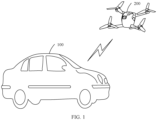
- the vehicle 100 may communicate with the flying apparatus 200 in a wireless manner.
- the vehicle 100 may communicate with the flying apparatus 200 in a manner such as ZigBee, Bluetooth, or Wi-Fi.
- the vehicle 100 may be a family car, a truck, a bus, or the like. This is not limited herein.
- the flying apparatus 200 may be a small rotary-wing unmanned aerial vehicle, for example, a four-rotary-wing unmanned aerial vehicle.
- One or more cameras may be disposed on the flying apparatus 200. Definition and an angle of view of each camera may be selected based on an actual requirement, for example, the camera is a high-definition camera or an ultra-high-definition camera.
- the flying apparatus 200 includes a front-view camera, a top-view camera, and a rear-view camera.
- the front-view camera may be configured to identify traffic information on each lane in front of the vehicle 100, status information of a traffic light, and the like.
- the top-view camera may be configured to identify information such as a pedestrian and a vehicle in an area into which the vehicle 100 is about to travel.
- the rear-view camera may be configured to provide traffic information on each lane behind the vehicle 100.
- a driver or a passenger of the vehicle 100 may enable the flying apparatus 200 in a manner such as a voice, a button operation, or a touchscreen operation.
- the parking slot 110 is disposed on the vehicle 100.
- the parking slot 110 is disposed on the top of the vehicle 100, that is, the recessed parking slot 110 is disposed at a position that is on the top of the vehicle and that is away from a vehicle sunroof.
- the parking slot 110 includes a bottom wall 112 and a side wall 114.
- a flow guiding slot 1121 and a wireless charging base 1122 are disposed on the bottom wall 112.
- a wireless charging receiver is correspondingly disposed at the bottom of the flying apparatus 200. When the wireless charging receiver of the flying apparatus 200 is attached to the wireless charging base 1122, a charging condition may be met, so that the vehicle 100 can charge the flying apparatus 200.
- the flow guiding slot 1121 disposed on the bottom wall 112 may facilitate heat dissipation of the flying apparatus 200 in a charging process.
- a direction of the flow guiding slot 1121 is basically the same as a direction in front of the vehicle 100.
- the direction of the flow guiding slot 1121 is basically parallel to the direction in front of the vehicle 100.
- the flow guiding slot 1121 may be of a straight line type, a fold line type, a wave type, or the like.
- the bottom wall 112 is further provided with a fastener 1123 and a slot 1124.
- a shape of the fastener 1123 is a "J" structure, and the fastener 1123 is configured to lock the flying apparatus 200.
- the slot 1124 is configured to connect inside and outside of the parking slot 110.
- rainwater may flow out along the slot 1124, so that the rainwater may be prevented from flooding the flying apparatus 200 and causing damage to a component of the flying apparatus 200.
- the slot 1124 passes through the interior of the vehicle top, and appearance does not affect a shape of the vehicle top.
- the parking slot 110 is disposed close to a C-pillar of the vehicle 100, and the slot 1124 is connected to the outside of a rear windshield, so that rainwater may flow out along the rear windshield.
- a contour of the parking slot 110 may also be similar to that of the flying apparatus 200, and may be slightly larger than a contour of the flying apparatus 200.
- the fastener 1123 may automatically lock the flying apparatus 200, so that the flying apparatus 200 does not move relative to the vehicle 100.
- the flying apparatus 200 may control the fastener 1123 to be loosened, so that the flying apparatus 200 meets a take-off condition.
- the fastener 1123 has a self-locking function. When the vehicle 100 is powered off, the fastener 1123 is locked, to prevent the flying apparatus 200 from being stolen. The fastener 1123 is opened only when the vehicle 100 is started and the flying apparatus 200 meets the take-off condition.
- a first circuit may be further disposed on the bottom wall 112, and a connection portion is disposed at the bottom of the flying apparatus 200. When the flying apparatus 200 lands in the parking slot 110, the first circuit forms a closed loop by using the connection portion, that is, the first circuit is connected, so that it can be determined that the flying apparatus 200 successfully lands in the parking slot 110. The flying apparatus 200 may send landing success information to the vehicle 100, to prompt the driver.
- the first circuit is an in-vehicle low-voltage circuit, for example, an in-vehicle 12 V circuit or an in-vehicle 24 V circuit.
- a slot 1124 may also be disposed on the side wall 114, so that the flying apparatus 200 dissipates heat in a charging process, and the flying apparatus 200 can also be prevented from being flooded by rainwater.
- the slot 1124 may also be a through hole, and the through hole is connected to inside and outside of the parking slot 110.
- one or more air blowing inlets 1125 are further provided on the side wall 114, and the air blowing inlets 1125 are connected to the air outlet of the vehicle 100.
- a rotation speed of a rotary wing is abnormal and is significantly lower than that of another rotary wing, the rotary wing may be entangled by some tree branches and leaves, and error correction is attempted on the flying apparatus 200.
- the air blowing inlet 1125 is opened, and air is blown to the flying apparatus 200 by using a circulating fan of the vehicle 100 until a rotation speed of each rotary wing is normal.
- the air blowing inlet 1125 In a normal state, the air blowing inlet 1125 is in a closed state, and no air is blown to the flying apparatus 200.
- the driver may be reminded, by using a voice or an in-vehicle display, that the flying apparatus 200 cannot take off normally, and the driver needs to assist in resolving the problem.
- the flying apparatus 200 When the flying apparatus 200 and the vehicle 100 meet a first preset condition, and the flying apparatus 200 receives a startup instruction sent by the vehicle 100, the flying apparatus 200 enters a self-test mode.
- the flying apparatus 200 may receive a startup instruction sent by the vehicle 100.
- take-off condition detection may be performed, that is, it is determined whether the flying apparatus 200 and the vehicle 100 meet the first preset condition, to determine whether the flying apparatus 200 may enter the self-test mode.
- the flying apparatus 200 and the vehicle 100 meet the first preset condition, it indicates that the flying apparatus 200 meets the take-off condition, and the flying apparatus 200 may enter the self-test mode.
- that the flying apparatus 200 and the vehicle 100 meet the first preset condition may be that power of the flying apparatus 200 meets a preset power requirement and a vehicle speed of the vehicle 100 meets a preset vehicle speed requirement.
- that the flying apparatus 200 and the vehicle 100 meet the first preset condition may alternatively be: remaining power of the flying apparatus 200 is greater than preset power, a vehicle speed of the vehicle 100 is lower than a preset vehicle speed, and the flying apparatus 200 communicates with the vehicle 100 normally.
- the remaining power of the flying apparatus 200 is greater than 50%, or the state of charge (State of Charge, SOC) of the flying apparatus 200 is greater than 0.5, and the vehicle speed of the vehicle 100 is lower than 70 km/h.
- That the flying apparatus 200 and the vehicle 100 meet the first preset condition may alternatively be: remaining power of the flying apparatus 200 is greater than preset power, a vehicle speed of the vehicle 100 is lower than a preset vehicle speed, a rainfall in a flight environment of the flying apparatus 200 is less than a preset rainfall, and the flying apparatus 200 communicates with the vehicle 100 normally.
- the remaining power of the flying apparatus 200 and the vehicle speed of the vehicle 100 may be obtained by using a known measurement method.
- the rainfall in the flight environment may be measured by using a rainfall sensor, or the rainfall in the flight environment may be obtained by obtaining a gear of a windshield wiper of the vehicle 100.
- the flying apparatus 200 when the flying apparatus 200 enters the self-test mode, the flying apparatus 200 performs self-test. In this case, the flying apparatus 200 is still locked in the parking slot 110 by the fastener 1123, and each rotary wing of the flying apparatus 200 may rotate at a relatively low preset rotation speed. It is determined, by detecting whether a rotation speed of each rotary wing is normal, whether the flying apparatus 200 succeeds in the self-test. For example, if a rotation speed of each rotary wing is a preset rotation speed, it is determined that the flying apparatus 200 succeeds in the self-test. If it is detected that a rotation speed of a rotary wing is abnormal or is significantly lower than that of another rotary wing, it is determined that the flying apparatus 200 fails in the self-test.
- the flying apparatus 200 obtains vehicle speed information of the vehicle 100.
- each rotary wing of the flying apparatus 200 rotates at a preset speed in the self-test mode, or each rotary wing rotates at a basically same speed in the self-test mode, for example, a speed difference falls within a preset percentage (for example, 5%).
- a preset percentage for example, 5%.
- the fastener 1123 before the flying apparatus 200 takes off, the fastener 1123 is in a locked state, and the flying apparatus 200 is locked in the parking slot 110.
- the fastener 1123 releases the flying apparatus 200, so that the flying apparatus 200 can take off from the parking slot 110.
- the flying apparatus 200 in the self-test mode, it is determined that the flying apparatus 200 fails in the self-test, and error correction may be attempted on the flying apparatus 200.
- the air blowing inlet 1125 is opened, and air is blown to the flying apparatus 200 by using a circulating fan of the vehicle 100.
- the preset prompt information may be output by using a voice or an in-vehicle display, to inform the driver that the flying apparatus 200 cannot take off normally, and the driver needs to assist in resolving the problem.
- a rotary wing when a rotary wing is entangled by tree branches or leaves, it cannot be ensured that the speeds of the rotary wings are the same by blowing air through the air blowing inlet 1125, and the driver needs to be instructed to assist in resolving the problem.
- the rotary wing or a rotary wing driving motor is abnormal, and consequently the speeds of the rotary wings are different, and the driver needs to be instructed to assist in resolving the problem.
- the flying apparatus 200 when the flying apparatus 200 succeeds in the self-test within a preset blowing time, it indicates that error correction on the flying apparatus 200 succeeds, the flying apparatus 200 meets the take-off condition, and the flying apparatus 200 may obtain the vehicle speed information of the vehicle 100.
- the information about the position of the flying apparatus 200 relative to the vehicle 100 may be obtained in real time.
- a wireless module is disposed on the flying apparatus 200, and the vehicle 100 may obtain the information about the position of the flying apparatus 200 relative to the vehicle 100 by measuring a radio signal strength of the wireless module.
- the flying apparatus 200 may be controlled, based on a current vehicle speed of the vehicle 100 and a current position of the flying apparatus 200 relative to the vehicle 100, to fly, so that a flight speed at which the flying apparatus 200 fly in front of the vehicle 100 is basically the same as the vehicle speed, and a specific relative position is maintained between the flying apparatus 200 and the vehicle.
- the flying apparatus 200 transmits, to the vehicle 100, a road condition image shot by a camera.
- the flying apparatus 200 keeps wireless communication with the vehicle 100.
- the flying apparatus 200 may transmit, to the vehicle 100 in real time, the road condition image shot by the camera.
- the road condition image received by the vehicle 100 may be displayed by using an in-vehicle display apparatus such as an in-vehicle display or a head-up display (Head-Up Display, HUD), or may be transmitted to an autonomous driving system for autonomous driving analysis.
- an in-vehicle display apparatus such as an in-vehicle display or a head-up display (Head-Up Display, HUD)
- HUD head-up display
- a first three-dimensional coordinate system S1 (flying apparatus coordinate system S1) is defined for the flying apparatus 200, where an X axis of the first three-dimensional coordinate system S1 is a front direction of the vehicle 100, a Y axis is a direction perpendicular to the X axis on a horizontal plane, and a Z axis is an upward direction perpendicular to an XY plane.
- a second three-dimensional coordinate system S2 vehicle coordinate system S2 having same directions as the first three-dimensional coordinate system S1 is defined for the vehicle 100; and a third three-dimensional coordinate system S3 having same directions as the first three-dimensional coordinate system S1 is defined for the camera.
- a three-dimensional coordinate system may be defined for each camera.
- a third three-dimensional coordinate system S3 is defined for the camera, and the road condition image is an image shot in the third three-dimensional coordinate system S3, that is, an image in an angle of view of the camera, and is not suitable for being directly displayed on the in-vehicle display apparatus.
- the vehicle 100 may first transform the road condition image shot by the camera into an image in an angle of view of the flying apparatus 200, that is, perform coordinate transformation on the road condition image shot in the third three-dimensional coordinate system S3, to obtain the first image in the flying apparatus coordinate system S1.
- coordinate transformation may be performed on a road condition image obtained by each camera (for example, a front-view camera, a top-view camera, or a rear-view camera) to obtain a plurality of first images in the flying apparatus coordinate system S1. Because the camera of the flying apparatus 200 is installed at a fixed position, a rule for coordinate transformation between each camera and the flying apparatus 200 may be defined based on an installation position of each camera.
- a first coordinate transformation rule for transforming a road condition image shot by the front-view camera into a road condition image in the flying apparatus coordinate system S1 may be defined based on an installation position of the front-view camera, so that coordinate transformation may be performed on the road condition image shot by the front-view camera according to the first coordinate transformation rule, to obtain an image in the flying apparatus coordinate system S1.
- a second coordinate transformation rule may be defined based on an installation position of the rear-view camera to transform a road condition image shot by the rear-view camera into the road condition image in the flying apparatus coordinate system, so that coordinate transformation may be performed on the road condition image shot by the rear-view camera according to the second coordinate transformation rule, to obtain another image in the flying apparatus coordinate system S1.
- the first image is an image in an angle of view of the flying apparatus 200 and is still not suitable for being displayed on the in-vehicle display apparatus, and coordinate transformation may be performed on the first image to obtain a second image in the vehicle coordinate system S2, that is, an image in an angle of view of the vehicle 100.
- coordinate transformation may be performed on the first image based on an actual position of the flying apparatus 200 in the vehicle coordinate system S2, to obtain the second image in the vehicle coordinate system S2.
- a coordinate position of a target object A1 in the flying apparatus coordinate system S1 is S 1,obj (x i , y i , z i )
- an actual position of the flying apparatus 200 in the vehicle coordinate system S2 is S 2,real (x 1 , y 1 , z 1 ).
- a coordinate position of the target object A1 in the vehicle coordinate system S2 may be obtained through conversion: S 2,real (x 1 , y 1 , z 1 ) + S 1,obj (x i , y i , z i ).
- the vehicle 100 may directly obtain, through measurement, the actual position of the flying apparatus 200 in the vehicle coordinate system S2.
- the actual position of the flying apparatus 200 in the vehicle coordinate system S2 may be obtained through measurement by using a positioning method based on a differential signal, a Bluetooth signal, and a Wi-Fi signal.
- a wireless module is disposed on the flying apparatus 200, and a radio signal detection module is disposed on the vehicle 100.
- the vehicle 100 measures a radio signal strength of the wireless module, and obtains, based on the radio signal strength, a first actual distance x 1 of the flying apparatus 200 relative to the coordinate origin of the vehicle coordinate system in the X-axis direction, a second actual distance yi of the flying apparatus 200 relative to the coordinate origin of the vehicle coordinate system in the Y-axis direction, and a third actual distance zi of the flying apparatus 200 relative to the coordinate origin of the vehicle coordinate system in the Z-axis direction.
- the second image in the vehicle coordinate system S2 when the second image in the vehicle coordinate system S2 is obtained, the second image may be displayed on the in-vehicle display apparatus, so that image information around the vehicle is obtained by using the flying apparatus 200, so that the driver makes an intelligent decision. For example, a pedestrian or a rider that is to rush out may be observed by using the top-view camera of the flying apparatus 200, so that the driver or an intelligent driving module makes a response in advance, thereby reducing traffic accidents.
- Information about a traffic light in front of the flying apparatus 200 may be displayed on the in-vehicle display apparatus by using the front-view camera of the flying apparatus 200, so that the driver is not blocked by a vehicle in front of the flying apparatus and can see the traffic light.
- traffic information of each lane may be displayed on the in-vehicle display apparatus in advance by using the front-view camera of the flying apparatus 200, so that the driver makes a lane change decision in advance, thereby improving traffic efficiency of the driver.
- the rear-view camera of the flying apparatus 200 may display information about a rear vehicle and a pedestrian on the in-vehicle display apparatus, so that the driver can make a safe driving decision.
- a road condition image shot by the flying apparatuses 200 may be shared, so that vehicle driving safety and road traffic efficiency can be further improved.
- the flying apparatus 200 and/or the vehicle 100 meet/meets a preset landing condition the flying apparatus 200 enters a return-for-landing mode.
- the flying apparatus 200 when the flying apparatus 200 and/or the vehicle 100 meet/meets a preset landing condition, the flying apparatus 200 enters a return-for-landing mode, to land in the parking slot 110.
- the preset landing condition may include at least one of the following: the flying apparatus 200 receives a return instruction sent by the vehicle 100, remaining power of the flying apparatus 200 is less than a preset threshold, a vehicle speed of the vehicle 100 is higher than a preset vehicle speed for a first preset time, a rainfall in a flight environment of the flying apparatus 200 is greater than a preset rainfall for a second preset time, and a communication exception occurs between the flying apparatus 200 and the vehicle 100 for a third preset time.
- the driver may control, by using a voice, a button operation, or a touchscreen operation, the vehicle 100 to send the return instruction to the flying apparatus 200 when the remaining power of the flying apparatus 200 is less than 10%, an SOC of the flying apparatus 200 is less than 0.1, a vehicle speed of the vehicle 100 is higher than 70 km/h for 30 seconds, and the rainfall in the flight environment is greater than the preset rainfall for 10 seconds (being greater than the preset rainfall may mean that the rainfall is greater than 15 mm, a wiping speed of the automatic windshield wiper is higher than a preset speed), or a communication exception occurs between the flying apparatus 200 and the vehicle 100 for 10 seconds.
- the flying apparatus 200 enters the return-for-landing mode, and the flying apparatus 200 tracks a center point of the parking slot 110 by using a camera, and adjusts a speed and a position of the flying apparatus 200 in the X-axis direction and a speed and a position of the flying apparatus 200 in the Y-axis direction, so that the center point of the parking slot 110 is in a same vertical direction as a center point of the flying apparatus 200, and a flight height of the flying apparatus 200 gradually decreases to a vehicle body height of the vehicle 100, so that the flying apparatus 200 lands in the parking slot 110.
- the vehicle 100 may determine that the flying apparatus 200 has landed in the parking slot 110.
- the vehicle 100 may control the fastener 1123 to lock the flying apparatus 200 in the parking slot 110, to prevent the flying apparatus 200 from being falling off or stolen.
- the in-vehicle display apparatus may output landing success prompt information, to prompt the driver.
- the flying apparatus 200 when the flying apparatus 200 stays in the parking slot 110, a locking signal of the fastener 1123 is normal, and the first circuit is in the connected state, it indicates that the flying apparatus 200 meets a charging condition.
- the driver may select the first charging mode (slow charging) or the second charging mode (fast charging) by using a voice, a button operation, a touch operation, or the like.
- the charging mode is the first charging mode, and a charging current in the second charging mode is greater than a charging current of the first charging mode.
- the flying apparatus 200 meets a charging condition, and remaining power of the flying apparatus 200 is less than a specific value (for example, less than 50%), the flying apparatus 200 is automatically charged in the first charging mode.
- the remaining power of the vehicle 100 is less than a specific value (for example, less than 20%), it may be determined that the power of the vehicle 100 is insufficient, a power consumption requirement of the vehicle 100 is preferentially considered, and automatic charging of the flying apparatus 200 is canceled, but the driver is allowed to forcibly enable a function of charging the flying apparatus 200.
- a specific value for example, less than 20%
- the wireless charging function is automatically disabled, and the flying apparatus 200 is in a sleep state.
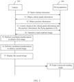
- the assisted driving method includes the following steps:
- the flying apparatus 200 may receive a startup instruction transmitted by the vehicle 100, where the start instruction is used to start the flying apparatus 200.
- the flying apparatus is provided with a camera for shooting a road condition image.
- the flying apparatus 200 when the power of the flying apparatus 200 meets the preset power requirement and the vehicle speed of the vehicle 100 meets the preset vehicle speed requirement, the flying apparatus 200 may be controlled to enter the self-test mode. For example, when the remaining power of the flying apparatus 200 is greater than 50%, and the vehicle speed of the vehicle 100 is lower than 70 km/h, the flying apparatus 200 may be controlled to enter the self-test mode. For another example, when the remaining power of the flying apparatus 200 is greater than 50%, the rainfall in the flight environment is less than 15 mm/1d, and the vehicle speed of the vehicle 100 is lower than 70 km/h, the flying apparatus 200 may be controlled to enter the self-test mode.
- that the flying apparatus 200 succeeds in the self-test means that each rotary wing of the flying apparatus 200 rotates at a preset rotation speed in the self-test mode, or each rotary wing rotates at a basically same rotation speed in the self-test mode (for example, a rotation speed difference is within 5%).
- the flying apparatus 200 succeeds in the self-test, it indicates that the flying apparatus 200 meets the take-off condition, and the flying apparatus 200 may communicate with the vehicle 100 to obtain the vehicle speed information of the vehicle 100.
- 506 Obtain information about a position of the flying apparatus 200 relative to the vehicle 100.
- the information about the position of the flying apparatus 200 relative to the vehicle 100 may be obtained in real time.
- a wireless module is disposed on the vehicle 100, and the flying apparatus 200 may obtain the information about the position of the flying apparatus 200 relative to the vehicle 100 by measuring a radio signal strength of the wireless module.
- Control based on the vehicle speed information and the position information, the flying apparatus 200 to fly.
- the flying apparatus 200 may be controlled, based on a current vehicle speed of the vehicle 100 and a current position of the flying apparatus 200 relative to the vehicle 100, to fly, so that a flight speed at which the flying apparatus 200 fly in front of the vehicle 100 is basically the same as the vehicle speed, and a specific relative position is maintained between the flying apparatus 200 and the vehicle.
- the flying apparatus 200 keeps wireless communication with the vehicle 100.
- the flying apparatus 200 may transmit, to the vehicle 100 in real time, the road condition image shot by the camera.
- the road condition image received by the vehicle 100 may be displayed by using an in-vehicle display apparatus such as an in-vehicle display or an HUD, or may be transmitted to an autonomous driving system for autonomous driving analysis.
- the flying apparatus 200 when the flying apparatus 200 and/or the vehicle 100 meet/meets the preset landing condition, the flying apparatus 200 may be controlled to enter the return-for-landing mode, to land in the parking slot 110.
- the preset landing condition may include at least one of the following: the flying apparatus 200 receives a return instruction sent by the vehicle 100, remaining power of the flying apparatus 200 is less than a preset threshold, a vehicle speed of the vehicle 100 is higher than a preset vehicle speed for a first preset time, a rainfall in a flight environment of the flying apparatus 200 is greater than a preset rainfall for a second preset time, and a communication exception occurs between the flying apparatus 200 and the vehicle 100 for a third preset time.
- the flying apparatus 200 is used to obtain the road condition image around the vehicle in real time, and transmit the road condition image to the vehicle for display or autonomous driving decision-making, so that driving safety of the vehicle and road traffic efficiency can be improved.
- the assisted driving method includes the following steps:
- a driver may control, by using a voice, a button operation, or a touchscreen operation, a vehicle 100 to send a startup instruction to the flying apparatus 200, where the startup instruction is used to start the flying apparatus 200.
- the flying apparatus is provided with a camera for shooting a road condition image.
- the flying apparatus 200 keeps wireless communication with the vehicle 100, and the vehicle 100 may receive the road condition image transmitted by the flying apparatus 200.
- 604 Perform coordinate transformation on the road condition image, and display the road condition image on an in-vehicle display apparatus of the vehicle 100.
- a first three-dimensional coordinate system S 1 is defined for the flying apparatus 200; a second three-dimensional coordinate system S2 having same directions as the first three-dimensional coordinate system S 1 is defined for the vehicle 100; and a third three-dimensional coordinate system S3 having same directions as the first three-dimensional coordinate system S 1 is defined for the camera.
- the vehicle 100 may perform coordinate transformation on the road condition image that is shot based on the third three-dimensional coordinate system S3 to obtain a first image in the first three-dimensional coordinate system S 1, perform coordinate transformation on the first image to obtain a second image in the second three-dimensional coordinate system S2, and display the second image on the in-vehicle display apparatus.
- the road condition image is an image shot in the third three-dimensional coordinate system S3, that is, an image in an angle of view of the camera, and is not suitable for being directly displayed on the in-vehicle display apparatus.
- the vehicle 100 may first transform the road condition image shot by the camera into an image at the angle of view of the flying apparatus 200, that is, perform coordinate transformation on the road condition image shot in the third three-dimensional coordinate system S3, to obtain a first image in the flying apparatus coordinate system S 1, and then perform coordinate transformation on the first image to obtain a second image in the vehicle coordinate system S2, that is, an image at the angle of view of the vehicle 100.
- the second image in the vehicle coordinate system S2 is obtained, the second image may be displayed on the in-vehicle display apparatus, so that image information around the vehicle is obtained by using the flying apparatus 200, so that the driver makes an intelligent decision.
- 606 Obtain information about a position of the flying apparatus 200 relative to the vehicle 100.
- the information about the position of the flying apparatus 200 relative to the vehicle 100 may be obtained in real time.
- a wireless module is disposed on the flying apparatus 200, and the vehicle 100 may obtain the information about the position of the flying apparatus 200 relative to the vehicle 100 by measuring a radio signal strength of the wireless module.
- Control based on the position information, the flying apparatus 200 to fly.
- the flying apparatus 200 may be controlled, based on a current position of the flying apparatus 200 relative to the vehicle 100, to fly, so that the flying apparatus 200 fly in front of the vehicle 100, and a specific relative position is maintained between the flying apparatus 200 and the vehicle.
- the flying apparatus 200 when the flying apparatus 200 and/or the vehicle 100 meet/meets a preset landing condition, the flying apparatus 200 is controlled to enter the return-for-landing mode, to land in the parking slot 110.
- the preset landing condition may include at least one of the following: the flying apparatus 200 receives a return instruction sent by the vehicle 100, remaining power of the flying apparatus 200 is less than a preset threshold, a vehicle speed of the vehicle 100 is higher than a preset vehicle speed for a first preset time, a rainfall in a flight environment of the flying apparatus 200 is greater than a preset rainfall for a second preset time, and a communication exception occurs between the flying apparatus 200 and the vehicle 100 for a third preset time.
- the flying apparatus 200 may optionally fly in front of the vehicle 100.
- a first target distance x des relative to an origin O1 of the vehicle coordinate system in the X-axis direction, a second target distance y des relative to an origin O1 of the vehicle coordinate system in the Y-axis direction, and a third target distance z des relative to an origin O1 of the vehicle coordinate system in the Z-axis direction are set for the flying apparatus 200.
- the first target distance x des may be represented as a function of a vehicle speed, an acceleration, and a steering wheel rotation angle, that is, the first target distance x des is determined based on a current vehicle speed, a current acceleration, and a current steering wheel rotation angle that are of the vehicle 100.
- the second target distance y des may be represented as a function of a preset time constant, a vehicle speed, an acceleration, and a steering wheel rotation angle, that is, the second target distance y des is determined based on the preset time constant, a current vehicle speed, a current acceleration, and a current steering wheel rotation angle that are of the vehicle 100.
- the preset time constant is t
- the third target distance z des may meet the following expression: z 2 + z 0 ⁇ z des ⁇ z 1 ⁇ z 0 .
- the flying apparatus 200 may determine a third target distance z des based on a height z 2 of the obstacle vehicle and the preset safe height z 0 .
- the flying apparatus 200 may determine a third target distance z des based on a height zi indicated by the height limit sign and a height z 2 of the obstacle vehicle.
- the vehicle 100 may obtain the first actual distance x 1 , the second actual distance yi, and the third actual distance zi that are of the flying apparatus 200 in the vehicle coordinate system S2 by measuring the radio signal strength of the wireless module of the flying apparatus 200.
- the first target distance x des , the second target distance y des , and the third target distance z des at the moment t i may be obtained based on the current vehicle speed, the current acceleration, and the current steering wheel rotation angle that are of the vehicle 100.
- a difference between the target position and the actual position may be calculated to obtain control values for the flying apparatus 200 in the X-axis direction, the Y-axis direction, and the Z-axis direction.
- a control value for the flying apparatus 200 in the X-axis direction is determined based on a difference between the first target distance x des and the first actual distance x 1 , so that the difference between the first target distance x de s and the first actual distance x 1 falls within a first preset range; and a control value for the flying apparatus 200 in the Y-axis direction is determined based on a difference between the second target distance y des and the second actual distance yi, so that the difference between the second target distance y des and the second actual distance yi falls within a second preset range; and a control value for the flying apparatus 200 in the Z-axis direction is determined based on a difference between the third target distance z des and the third actual distance zi, so that the difference between the third target distance z des and the third actual distance zi falls within a third preset range.
- the first preset range, the second preset range, and the third preset range may all be set according to an actual requirement.
- parameters v, a, ⁇ , zi, and z 2 will change, that is, the first target distance x des , the second target distance y des , and the third target distance z des may be adjusted at any time.
- a current actual position of the flying apparatus 200 is obtained to dynamically adjust flight of the flying apparatus 200 in real time, so that the difference between the first target distance x des and the first actual distance x 1 falls within the first preset range, the difference between the second target distance y des and the second actual distance yi falls within the second preset range, and the difference between the third target distance z des and the third actual distance zi falls within the third preset range.
- control values for the flying apparatus 200 in the X-axis direction, the Y-axis direction, and the Z-axis direction may be obtained through calculation according to the following formulas: S 2,des (x des , y des , z des )-S 2,real (x 1 , y 1 , z 1 ).
- FIG. 9 is a schematic diagram of functional modules of a first assisted driving apparatus 300 according to an embodiment of this application.
- the first assisted driving apparatus 300 may be applied to the flying apparatus 200, and the flying apparatus 200 is in communication connection to the vehicle 100.
- the first assisted driving apparatus 300 may include a first receiving module 301, a first control module 302, a first obtaining module 303, a second control module 304, and a transmission module 305.
- the module described in the embodiments of the present invention may be a program segment for completing a specific function, and is more suitable for describing an execution process of software in a processor than a program.
- the one or more modules may be stored in the memory and configured to be executed by one or more processors.
- the first receiving module 301 is configured to receive a startup instruction.
- the startup instruction is used to start the flying apparatus 200.
- the first control module 302 is configured to: when the power of the flying apparatus 200 meets a preset power requirement and a vehicle speed of the vehicle 100 meets a preset vehicle speed requirement, control the flying apparatus 200 to enter a self-test mode.
- the first obtaining module 303 is configured to obtain vehicle speed information of the vehicle 100 when the flying apparatus 200 succeeds in the self-test.
- the first obtaining module 303 is further configured to obtain information about a position of the flying apparatus 200 relative to the vehicle 100.
- the second control module 304 is configured to control, based on the vehicle speed information and the position information, the flying apparatus 200 to fly.
- the transmission module 305 is configured to transmit, to the vehicle 100, a road condition image shot by a camera.
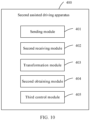
- FIG. 10 is a schematic diagram of functional modules of a second assisted driving apparatus 400 according to an embodiment of this application.
- the second assisted driving apparatus 400 may be applied to the vehicle 100, and the flying apparatus 200 is in communication connection to the vehicle 100.
- the second assisted driving apparatus 400 may include a sending module 401, a second receiving module 402, a transformation module 403, a second obtaining module 404, and a third control module 405.
- the module described in the embodiments of the present invention may be a program segment for completing a specific function, and is more suitable for describing an execution process of software in a processor than a program.
- the one or more modules may be stored in the memory and configured to be executed by one or more processors.
- the sending module 401 is configured to send a startup instruction to the flying apparatus 200, where the startup instruction is used to start the flying apparatus 200.
- a camera is disposed on the flying apparatus 200.
- the second receiving module 402 is configured to receive a road condition image that is transmitted by the flying apparatus 200 and that is shot by a camera.
- the transformation module 403 is configured to perform coordinate transformation on the road condition image, and display the road condition image on the in-vehicle display apparatus of the vehicle 100.
- the second obtaining module 404 is configured to obtain information about a position of the flying apparatus 200 relative to the vehicle 100.
- the third control module 405 is configured to control, based on the position information, the flying apparatus 200 to fly.
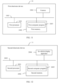
- FIG. 11 is a schematic diagram of a hardware structure of a first electronic device 10 according to an embodiment of this application.
- the first electronic device 10 may include a first processor 1001, a first memory 1002, a first communication bus 1003, and a camera 1004.
- the first memory 1002 is configured to store one or more first computer programs 1005.
- the one or more first computer programs 1005 are configured to be executed by the first processor 1001.
- the one or more first computer programs 1005 include instructions, and the instructions may be used to perform the assisted driving method shown in FIG. 5 in the first electronic device 10.
- the structure shown in this embodiment does not constitute a specific limitation on the first electronic device 10.
- the first electronic device 10 may include more or fewer components than those shown in the figure, or combine some components, or split some components, or have different component arrangements.
- FIG. 12 is a schematic diagram of a hardware structure of a second electronic device 11 according to an embodiment of this application.
- the second electronic device 11 may include a second processor 2001, a second memory 2002, a second communication bus 2003, and an in-vehicle display apparatus 2004.
- the second memory 2002 is configured to store one or more second computer programs 2005.
- the one or more second computer programs 2005 are configured to be executed by the second processor 2001.
- the one or more second computer programs 2005 include instructions, and the instructions may be used to perform the assisted driving method shown in FIG. 6 in the second electronic device 11.
- the structure shown in this embodiment does not constitute a specific limitation on the second electronic device 11.
- the second electronic device 11 may include more or fewer components than those shown in the figure, or combine some components, or split some components, or have different component arrangements.
- Both the first processor 1001 and the second processor 2001 may include one or more processing units.
- the first processor 1001 may include an application processor (application processor, AP), a modem, a graphics processing unit (graphics processing unit, GPU), an image signal processor (image signal processor, ISP), a controller, a video codec, a digital signal processor (digital signal processor, DSP), a baseband processor, a neural network processor (neural-network processing unit, NPU), and/or the like.
- Different processing units may be independent components, or may be integrated into one or more processors.
- the first processor 1001 and the second processor 2001 may be further provided with a memory, configured to store instructions and data.
- memories in the first processor 1001 and the second processor 2001 are caches.
- the memory may store instructions or data that is just used or cyclically used by the first processor 1001 (the second processor 2001). If the first processor 1001 (the second processor 2001) needs to use the instructions or the data again, the instructions or the data may be directly invoked from the memory. This avoids repeated access and reduces a waiting time of the first processor 1001 (the second processor 2001), thereby improving system efficiency.
- both the first processor 1001 and the second processor 2001 may include one or more interfaces.
- the interface may include an inter-integrated circuit (inter-integrated circuit, I2C) interface, an inter-integrated circuit sound (inter-integrated circuit sound, I2S) interface, a pulse code modulation (pulse code modulation, PCM) interface, a universal asynchronous receiver/transmitter (universal asynchronous receiver/transmitter, UART) interface, a mobile industry processor interface (mobile industry processor interface, MIPI), a general-purpose input/output (general-purpose input/output, GPIO) interface, a SIM interface, a USB interface, and/or the like.
- I2C inter-integrated circuit
- I2S inter-integrated circuit sound
- PCM pulse code modulation
- PCM pulse code modulation
- UART universal asynchronous receiver/transmitter
- MIPI mobile industry processor interface
- GPIO general-purpose input/output
- both the first memory 1002 and the second memory 2002 may include a high-speed random access memory, and may further include a non-volatile memory, for example, a hard disk, a memory, a plug-in hard disk, a smart memory card (Smart Media Card, SMC), a secure digital (Secure Digital, SD) card, a flash card (Flash Card), at least one magnetic disk storage device, a flash memory device, or another volatile solid-state storage device.
- a non-volatile memory for example, a hard disk, a memory, a plug-in hard disk, a smart memory card (Smart Media Card, SMC), a secure digital (Secure Digital, SD) card, a flash card (Flash Card), at least one magnetic disk storage device, a flash memory device, or another volatile solid-state storage device.
- a non-volatile memory for example, a hard disk, a memory, a plug-in hard disk, a smart memory card (Smart Media Card, SMC), a secure digital (S
- An embodiment further provides a computer storage medium.
- the computer storage medium stores computer instructions.
- the computer instructions When the computer instructions are run on an electronic device, the electronic device is enabled to perform the foregoing related method steps to implement the assisted driving methods in the foregoing embodiments.
- An embodiment further provides a computer program product.
- the computer program product runs on a computer, the computer is enabled to perform the foregoing related steps, to implement the assisted driving methods in the foregoing embodiments.
- an embodiment of this application further provides an apparatus.
- the apparatus may be specifically a chip, a component, or a module, and the apparatus may include a processor and a memory that are connected.
- the memory is configured to store computer-executable instructions.
- the processor may execute the computer-executable instructions stored in the memory, to enable a chip to perform the assisted driving methods in the foregoing method embodiments.
- the first electronic device, the second electronic device, the computer storage medium, the computer program product, or the chip provided in embodiments is configured to perform the corresponding methods provided above. Therefore, for beneficial effects that can be achieved, refer to the beneficial effects of the corresponding methods provided above. Details are not described herein again.
- the disclosed apparatus and method may be implemented in other manners.
- the described apparatus embodiment is an example.
- division into modules or units is logical function division and may be another division manner in actual implementation.
- a plurality of units or components may be combined or integrated into another apparatus, or some features may be ignored or not performed.
- the displayed or discussed mutual couplings or direct couplings or communication connections may be implemented by using some interfaces.
- the indirect couplings or communication connections between the apparatuses or units may be implemented in electronic, mechanical, or other forms.
- the units described as separate parts may or may not be physically separate, and parts displayed as units may be one or more physical units, may be located in one place, or may be distributed on different places. Some or all of the units may be selected according to an actual requirement to achieve the objectives of the solutions of embodiments.
- functional units in embodiments of this application may be integrated into one processing unit, each of the units may exist alone physically, or two or more units are integrated into one unit.
- the integrated unit may be implemented in a form of hardware, or may be implemented in a form of a software functional unit.
- the integrated unit When the integrated unit is implemented in a form of a software functional unit and sold or used as an independent product, the integrated unit may be stored in a readable storage medium.
- the technical solutions in embodiments of this application essentially, or the part contributing to the conventional technology, or all or some of the technical solutions may be implemented in the form of a software product.
- the software product is stored in a storage medium and includes several instructions for instructing a device (which may be a single-chip microcomputer, a chip, or the like) or a processor (processor) to perform all or some of the steps of the methods described in embodiments of this application.
- the foregoing storage medium includes any medium that can store program code, such as a USB flash drive, a removable hard disk, a read-only memory (Read-Only Memory, ROM), a random access memory (Random Access Memory, RAM), a magnetic disk, or an optical disc.
- program code such as a USB flash drive, a removable hard disk, a read-only memory (Read-Only Memory, ROM), a random access memory (Random Access Memory, RAM), a magnetic disk, or an optical disc.
Landscapes
- Physics & Mathematics (AREA)
- General Physics & Mathematics (AREA)
- Engineering & Computer Science (AREA)
- Power Engineering (AREA)
- Transportation (AREA)
- Mechanical Engineering (AREA)
- Chemical & Material Sciences (AREA)
- Analytical Chemistry (AREA)
- Life Sciences & Earth Sciences (AREA)
- Atmospheric Sciences (AREA)
- Traffic Control Systems (AREA)
Abstract
Description
- This application relates to the field of intelligent driving, and specifically, to an assisted driving method, a parking slot, a chip, an electronic device, and a computer-readable storage medium.
- In a traffic scenario, traffic accidents are often caused because a blind spot blocks a driver's field of view or a sensing range of a sensor configured on a vehicle. For example, in an urban traffic scenario, when a vehicle is blocked by another vehicle, building, or facility, a sensor configured for a driver or a vehicle cannot obtain enough environment information, and therefore the driver cannot make a timely and reasonable decision, causing a traffic accident. When a side vehicle blocks the line of sight, due to existence of a blind spot, the driver may not have time to brake when facing a pedestrian or a rider who suddenly rushes out, which may cause a traffic accident. When a vehicle turns right at an intersection, pedestrians and riders on the right non-motor lane cannot be observed at a specific position due to existence of a blind spot in the rear-view mirror, which may also cause a traffic accident. A blind spot may also affect traffic efficiency. For example, when following a high vehicle during driving, a driver may not be able to observe a status of a traffic light in front of the vehicle. As a result, the driver cannot make the most reasonable driving decision. When a plurality of lanes are travelable, because a driver usually cannot observe a status of each lane ahead, the driver cannot make the most reasonable lane selection decision. When a driver is driving on a two-way lane and a vehicle ahead is high, if the driver needs to overtake, the driver may need to frequently change to the opposite lane to try to overtake. If the driver finds that there is no vehicle on the opposite lane and a condition for overtaking is met, the driver performs overtaking, which affects traffic efficiency.
- In a conventional technology, for this case, a method of adding a liquid crystal display to the rear of a vehicle is proposed. The vehicle ahead displays information about traffic ahead on the display of the vehicle ahead in real time, so that a driver of the rear vehicle can observe whether a pedestrian is crossing a road ahead, whether a condition for overtaking is met, and the like. However, this method is costly and difficult to popularize. In addition, it is difficult to install a display on a trunk of a passenger car, and it is not easy to be accepted by consumers.
- In view of the foregoing content, it is necessary to provide an assisted driving method, an apparatus, a computer device, and a computer-readable storage medium, so as to collect road conditions ahead by using a flying apparatus that communicates with a vehicle, and send the road conditions back to the vehicle for display.
- A first aspect of the embodiments of this application discloses an assisted driving method, including: receiving a startup instruction, where the startup instruction is used to start a flying apparatus, and a camera is disposed on the flying apparatus; controlling the flying apparatus to enter a self-test mode when power of the flying apparatus meets a preset power requirement and a vehicle speed of a vehicle meets a preset vehicle speed requirement; obtaining vehicle speed information of the vehicle when the flying apparatus succeeds in the self-test; obtaining information about a position of the flying apparatus relative to the vehicle; controlling, based on the vehicle speed information and the position information, the flying apparatus to fly; and transmitting, to the vehicle, a road condition image shot by the camera.
- According to this technical solution, the flying apparatus is used to obtain the road condition image around the vehicle in real time, and transmit the road condition image to the vehicle, so as to improve driving safety of the vehicle and road traffic efficiency.
- In a possible implementation, the controlling the flying apparatus to enter a self-test mode when power of the flying apparatus meets a preset power requirement and a vehicle speed of a vehicle meets a preset vehicle speed requirement includes: when remaining power of the flying apparatus is greater than preset power, the vehicle speed of the vehicle is lower than a preset vehicle speed, and communication between the flying apparatus and the vehicle is normal, controlling the flying apparatus to enter the self-test mode; or when remaining power of the flying apparatus is greater than preset power, the vehicle speed of the vehicle is lower than a preset vehicle speed, a rainfall in a flight environment of the flying apparatus is less than a preset rainfall, and communication between the flying apparatus and the vehicle is normal, controlling the flying apparatus to enter the self-test mode.
- According to this technical solution, the flying apparatus enters a take-off preparation phase only when the flying apparatus receives the startup instruction and a preset take-off policy is met, so as to prevent the flying apparatus from flying in an inappropriate flight condition.
- In a possible implementation, the flying apparatus includes a plurality of rotary wings, and that the flying apparatus succeeds in the self-test includes: each of the rotary wings rotates at a preset rotation speed in a take-off preparation mode.
- According to this technical solution, when the flying apparatus enters the take-off preparation phase, self-test is performed on the rotary wings, so as to avoid a flight exception of the flying apparatus.
- In a possible implementation, the assisted driving method further includes: when the flying apparatus and/or the vehicle meet/meets a preset landing condition, controlling the flying apparatus to enter a return-for-landing mode, where the preset landing condition includes at least one of the following: the flying apparatus receives a return instruction; the remaining power of the flying apparatus is less than a preset threshold; the vehicle speed of the vehicle is higher than the preset vehicle speed for a first preset time; the rainfall in the flight environment of the flying apparatus is greater than the preset rainfall for a second preset time; and a communication exception occurs between the flying apparatus and the vehicle for a third preset time.
- According to this technical solution, when a preset return policy is met during flight of the flying apparatus, the flying apparatus may be controlled to return for landing.
- In a possible implementation, the vehicle is provided with a parking slot for parking the flying apparatus, and the controlling the flying apparatus to enter a return-for-landing mode includes: controlling the flying apparatus to track a center point of the parking slot by using the camera, and adjusting a speed and a position of the flying apparatus in an X-axis direction and a speed and a position of the flying apparatus in a Y-axis direction, so that the center point of the parking slot is in a same vertical direction as a center point of the flying apparatus; and adjusting a flight height of the flying apparatus to land in the parking slot.
- According to this technical solution, in a process of returning for landing, the flying apparatus lands in the parking slot by tracking the center point of the parking slot and adjusting the flight height.
- In a possible implementation, the vehicle is provided with a parking slot for parking the flying apparatus, an air blowing inlet is provided on a side wall of the parking slot, and the assisted driving method further includes: when the flying apparatus fails in the self-test, blowing air to the flying apparatus by using the air blowing inlet; or when the flying apparatus succeeds in the self-test within a preset blowing time, obtaining the vehicle speed information of the vehicle; or when the flying apparatus still fails in the self-test within the preset blowing time, outputting preset prompt information to the vehicle.
- According to this technical solution, when the flying apparatus fails in the self-test, air is blown to the flying apparatus by using a preset error correction policy. When the error correction succeeds, the flying apparatus may take off normally; or when the error correction fails, the driver is reminded to assist in resolving the problem.
- In a possible implementation, when the flying apparatus succeeds in the self-test, the parking slot is switched from a locked state to a loosened state.
- According to this technical solution, when the flying apparatus succeeds in the self-test, the parking slot releases the flying apparatus, so that the flying apparatus can take off.
- In a possible implementation, a vehicle coordinate system is defined for the vehicle, and the obtaining information about a position of the flying apparatus relative to the vehicle includes: obtaining a first actual distance of the flying apparatus relative to a coordinate origin of the vehicle coordinate system in an X-axis direction, a second actual distance of the flying apparatus relative to a coordinate origin of the vehicle coordinate system in a Y-axis direction, and a third actual distance of the flying apparatus relative to a coordinate origin of the vehicle coordinate system in a Z-axis direction.
- In a possible implementation, a first target distance relative to the coordinate origin of the vehicle coordinate system in the X-axis direction, a second target distance relative to the coordinate origin of the vehicle coordinate system in the Y-axis direction, and a third target distance relative to the coordinate origin of the vehicle coordinate system in the Z-axis direction are set for the flying apparatus, and the controlling, based on the vehicle speed information and the position information, the flying apparatus to fly includes: controlling, based on the vehicle speed information, a difference between the first target distance and the first actual distance, a difference between the second target distance and the second actual distance, and a difference between the third target distance and the third actual distance, the flying apparatus to fly.
- According to this technical solution, in the vehicle coordinate system, a target position and an actual position of the flying apparatus are obtained, and a flight distance of the flying apparatus relative to the vehicle is controlled based on the vehicle speed and a difference between the target position and the actual position.
- In a possible implementation, the assisted driving method further includes: setting the first target distance according to a vehicle speed, an acceleration, and a steering wheel rotation angle that are of the vehicle, where the first target distance is positively correlated with the vehicle speed and the acceleration of the vehicle, and the first target distance is negatively correlated with the steering wheel rotation angle of the vehicle; setting the second target distance according to a preset time constant and the vehicle speed, the acceleration, and the steering wheel rotation angle that are of the vehicle, where the second target distance is positively correlated with the vehicle speed and the acceleration of the vehicle, and the second target distance is negatively correlated with the steering wheel rotation angle of the vehicle; and when it is determined, based on the road condition image, that there is a height limit sign in front of the vehicle, setting the third target distance according to a height marked by the height limit sign and a preset safe height.
- According to this technical solution, the distances of the flying apparatus relative to the vehicle on the X axis and the Y axis can be determined based on the vehicle speed, the acceleration, and the steering wheel rotation angle that are of the vehicle, and the distance of the flying apparatus relative to the vehicle on the Z axis can be determined based on the height limit sign and the preset safe height.
- In a possible implementation, the assisted driving method further includes: when it is determined, based on the road condition image, that there is a height limit sign and an obstacle vehicle in front of the vehicle, setting the third target distance according to the height marked by the height limit sign and a height of the obstacle vehicle; or when it is determined, based on the road condition image, that there is an obstacle vehicle in front of the vehicle, setting the third target distance according to a height of the obstacle vehicle and the preset safe height; or when it is determined, based on the road condition image, that there is neither a height limit sign nor an obstacle vehicle in front of the vehicle, setting the third target distance as the preset safe height.
- A second aspect of the embodiments of this application discloses an assisted driving method, including: sending a startup instruction to a flying apparatus, where the startup instruction is used to start the flying apparatus, and a camera is disposed on the flying apparatus; receiving a road condition image that is transmitted by the flying apparatus and that is shot by the camera; performing coordinate transformation on the road condition image, and displaying the road condition image on an in-vehicle display apparatus of a vehicle; obtaining information about a position of the flying apparatus relative to the vehicle; and controlling, based on the position information, the flying apparatus to fly.
- According to this technical solution, the flying apparatus is used to obtain the road condition image around the vehicle in real time, and transmit the road condition image to the vehicle; and the vehicle performs flight control on the flying apparatus, and performs coordinate transformation on the received road condition image, so as to display the road condition image on the in-vehicle display apparatus, thereby improving driving safety of the vehicle and road traffic efficiency.
- In a possible implementation, a vehicle coordinate system is defined for the vehicle, and the obtaining information about a position of the flying apparatus relative to the vehicle includes: obtaining a first actual distance of the flying apparatus relative to a coordinate origin of the vehicle coordinate system in an X-axis direction, a second actual distance of the flying apparatus relative to a coordinate origin of the vehicle coordinate system in a Y-axis direction, and a third actual distance of the flying apparatus relative to a coordinate origin of the vehicle coordinate system in a Z-axis direction.
- In a possible implementation, a first target distance relative to the coordinate origin of the vehicle coordinate system in the X-axis direction, a second target distance relative to the coordinate origin of the vehicle coordinate system in the Y-axis direction, and a third target distance relative to the coordinate origin of the vehicle coordinate system in the Z-axis direction are set for the flying apparatus, and the controlling, based on the position information, the flying apparatus to fly includes: determining a control value for the flying apparatus in the X-axis direction based on a difference between the first target distance and the first actual distance, so that the difference between the first target distance and the first actual distance falls within a first preset range; determining a control value for the flying apparatus in the Y-axis direction based on a difference between the second target distance and the second actual distance, so that the difference between the second target distance and the second actual distance falls within a second preset range; and determining a control value for the flying apparatus in the Z-axis direction based on a difference between the third target distance and the third actual distance, so that the difference between the third target distance and the third actual distance falls within a third preset range.
- According to this technical solution, in the vehicle coordinate system, a target position and an actual position of the flying apparatus are obtained, and the control values for the flying apparatus on an X axis, a Y axis, and a Z axis are determined based on a difference between the target position and the actual position, so as to control a flight distance of the flying apparatus relative to the vehicle.
- In a possible implementation, the assisted driving method further includes: setting the first target distance according to a vehicle speed, an acceleration, and a steering wheel rotation angle that are of the vehicle, where the first target distance is positively correlated with the vehicle speed and the acceleration of the vehicle, and the first target distance is negatively correlated with the steering wheel rotation angle of the vehicle; setting the second target distance according to a preset time constant and the vehicle speed, the acceleration, and the steering wheel rotation angle that are of the vehicle, where the second target distance is positively correlated with the vehicle speed and the acceleration of the vehicle, and the second target distance is negatively correlated with the steering wheel rotation angle of the vehicle; and when it is determined, based on the road condition image, that there is a height limit sign in front of the vehicle, setting the third target distance according to a height marked by the height limit sign and a preset safe height.
- According to this technical solution, the distances of the flying apparatus relative to the vehicle on the X axis and the Y axis can be determined based on the vehicle speed, the acceleration, and the steering wheel rotation angle that are of the vehicle, and the distance of the flying apparatus relative to the vehicle on the Z axis can be determined based on the height limit sign and the preset safe height.
- In a possible implementation, the assisted driving method further includes: when it is determined, based on the road condition image, that there is a height limit sign and an obstacle vehicle in front of the vehicle, setting the third target distance according to the height marked by the height limit sign and a height of the obstacle vehicle; or when it is determined, based on the road condition image, that there is an obstacle vehicle in front of the vehicle, setting the third target distance according to a height of the obstacle vehicle and the preset safe height; or when it is determined, based on the road condition image, that there is neither a height limit sign nor an obstacle vehicle in front of the vehicle, setting the third target distance as the preset safe height.
- In a possible implementation, a flying apparatus coordinate system is defined for the flying apparatus, and the performing coordinate transformation on the road condition image includes: performing first coordinate transformation on the road condition image to obtain the road condition image in the flying apparatus coordinate system; and performing second coordinate transformation on the road condition image in the flying apparatus coordinate system, to obtain a road condition image in the vehicle coordinate system.
- According to this technical solution, coordinate transformation may be performed on a road condition image shot by a camera, to obtain the road condition image in the vehicle coordinate system, so as to display the road condition image on an in-vehicle display device.
- In a possible implementation, the flying apparatus is further provided with a wireless module, and the obtaining a first actual distance of the flying apparatus relative to a coordinate origin of the vehicle coordinate system in an X-axis direction, a second actual distance of the flying apparatus relative to a coordinate origin of the vehicle coordinate system in a Y-axis direction, and a third actual distance of the flying apparatus relative to a coordinate origin of the vehicle coordinate system in a Z-axis direction includes: measuring a radio signal strength of the wireless module, and obtaining, based on the radio signal strength, a first actual distance of the flying apparatus relative to the coordinate origin of the vehicle coordinate system in the X-axis direction, a second actual distance of the flying apparatus relative to the coordinate origin of the vehicle coordinate system in the Y-axis direction, and a third actual distance of the flying apparatus relative to the coordinate origin of the vehicle coordinate system in the Z-axis direction.
- According to this technical solution, the actual position of the flying apparatus may be obtained, through measurement, in a radio signal positioning manner.
- In a possible implementation, the vehicle is provided with a parking slot for parking the flying apparatus, the parking slot is provided with a fastener and a first circuit, and the assisted driving method further includes: when it is detected that the first circuit is in a connected state, determining that the flying apparatus has landed in the parking slot; controlling the fastener to lock the flying apparatus in the parking slot; and when it is detected that the fastener successfully locks the flying apparatus, outputting landing success prompt information.
- According to this technical solution, it may be determined, by determining whether the first circuit is connected and whether the fastener successfully locks the flying apparatus, whether the flying apparatus successfully lands in the parking slot.
- In a possible implementation, the assisted driving method further includes: when the flying apparatus successfully lands, power of the flying apparatus is less than first preset power, and power of the vehicle is greater than second preset power, charging the flying apparatus in a first charging mode; or when a charging control instruction is received, charging the flying apparatus according to the charging control instruction, where the charging control instruction includes the first charging mode or a second charging mode, and a charging current of the second charging mode is greater than a charging current of the first charging mode.
- According to this technical solution, when the flying apparatus meets a preset charging condition, the flying apparatus may be charged by using different charging policies.
- A third aspect of the embodiments of this application discloses a parking slot, disposed on a vehicle and configured to lock a flying apparatus, where the parking slot includes a bottom wall and a side wall, a flow guiding slot and a wireless charging base are disposed on the bottom wall, the wireless charging base is configured to charge the flying apparatus, a direction of the flow guiding slot is substantially parallel to a front direction of the vehicle, a fastener is further disposed on the bottom wall, the fastener is further disposed to lock the flying apparatus, and/or the bottom wall and/or the side wall are/is provided with a slot, so as to connect inside and outside of the parking slot.
- According to this technical solution, a parking slot is disposed on a vehicle, to lock the flying apparatus that lands in the parking slot, so as to prevent the flying apparatus from being stolen or falling off when the vehicle is traveling.
- In a possible implementation, a shape of the flow guiding slot is any one of a straight line type, a fold line type, or a wave type, and the fastener is of a "J" type structure.
- In a possible implementation, an air blowing inlet is further provided on the side wall, and the air blowing inlet is connected to an air outlet of the vehicle.
- According to this technical solution, the air blowing inlet is provided in the parking slot, so that the flying apparatus can be blown when the flying apparatus is in an error correction phase.
- In a possible implementation, a first circuit is further disposed on the bottom wall, a connection portion is disposed at the bottom of the flying apparatus, and when the flying apparatus lands in the parking slot, the first circuit forms a closed loop by using the connection portion.
- According to this technical solution, it may be determined, by determining whether the first circuit is in a connected state, whether the flying apparatus lands in the parking slot.
- According to a fourth aspect, an embodiment of this application provides a computer-readable storage medium, including computer instructions. When the computer instructions are run on an electronic device, the electronic device is enabled to perform the assisted driving method according to the first aspect or perform the assisted driving method according to the second aspect.
- According to a fifth aspect, an embodiment of this application provides an electronic device. The electronic device includes a processor and a memory, the memory is configured to store instructions, and the processor is configured to invoke the instructions in the memory, so that the electronic device performs the assisted driving method according to the first aspect or performs the assisted driving method according to the second aspect.
- According to a sixth aspect, an embodiment of this application provides a computer program product. When the computer program product runs on a computer, the computer is enabled to perform the assisted driving method according to the first aspect or perform the assisted driving method according to the second aspect.
- According to a seventh aspect, an embodiment of this application provides an apparatus. The apparatus has a function of implementing behavior of the electronic device in the method according to the first aspect or the second aspect. The function may be implemented by hardware, or may be implemented by hardware executing corresponding software. The hardware or software includes one or more modules corresponding to the foregoing function.
- It may be understood that the computer-readable storage medium according to the fourth aspect, the electronic device according to the fifth aspect, the computer program product according to the sixth aspect, and the apparatus according to the seventh aspect all correspond to the method according to the first aspect or the second aspect. Therefore, for beneficial effects that can be achieved by the storage medium, the electronic device, the computer program product, and the apparatus, refer to beneficial effects in the corresponding methods provided above, and details are not described herein again.
-
-
FIG. 1 is a diagram of an application scenario of an assisted driving method according to an embodiment of this application; -
FIG. 2 is a schematic diagram of a possible structure of a parking slot according to an embodiment of this application; -
FIG. 3 is a schematic diagram of data exchange between a vehicle and a flying apparatus according to an embodiment of this application; -
FIG. 4 is a schematic flowchart of performing coordinate transformation on a first image according to an embodiment of this application; -
FIG. 5 is a schematic flowchart of an assisted driving method according to an embodiment of this application; -
FIG. 6 is a schematic flowchart of an assisted driving method according to another embodiment of this application; -
FIG. 7 is a schematic diagram of target distances of a flying apparatus in all directions in a vehicle coordinate system according to an embodiment of this application; -
FIG. 8 is a schematic flowchart of calculating a control value for a flying apparatus in each direction in a vehicle coordinate system according to an embodiment of this application; -
FIG. 9 is a schematic diagram of functional modules of a first assisted driving apparatus according to an embodiment of this application; -
FIG. 10 is a schematic diagram of functional modules of a second assisted driving apparatus according to an embodiment of this application; -
FIG. 11 is a schematic diagram of a possible structure of a first electronic device according to an embodiment of this application; and -
FIG. 12 is a schematic diagram of a possible structure of a second electronic device according to an embodiment of this application. - To better understand the foregoing objectives, features, and advantages of this application, the following describes this application in detail with reference to the accompanying drawings and specific embodiments. It should be noted that embodiments of this application and the features in embodiments may be combined with each other provided that no conflict occurs.
- It should be noted that, in this application, "at least one" means one or more, and "a plurality of" means two or more. "And/or" describes an association relationship between associated objects, and represents that three relationships may exist. For example, A and/or B may represent the following cases: Only A exists, both A and B exist, and only B exists, where A and B may be singular or plural. In this specification, claims, and accompanying drawings of this application, terms "first", "second", "third", "fourth", and the like (if existent) are intended to distinguish between similar objects but do not necessarily indicate a specific order or sequence.
- Vehicle to X (Vehicle to X, V2X) is information exchange between a vehicle and the outside. This technology is the ultimate ideal form of the future Internet of Vehicles (IoV) and connects vehicles to vehicles, vehicles to infrastructure, vehicles to pedestrians, and the like. In this case, the vehicle may communicate with traffic infrastructure (for example, a camera on a road) to observe information about a vehicle and a pedestrian in each direction, and a blind spot basically disappears, so that a problem caused by the blind spot can be avoided. However, the V2X technology requires a large amount of investment in implementation, and infrastructure construction requires a large amount of capital investment, the deployment period is long, and the V2X technology cannot be popularized in a short time. This application provides an assisted driving method. A flying apparatus may be used as a "pilot". The flying apparatus is equipped with one or more high-definition cameras, and sends, in real time by flying in front of a vehicle, a photographed traffic road condition to the vehicle for display, to resolve a traffic safety problem caused by a blind spot.
- With reference to
FIG. 1 , the following describes an example of an application scenario diagram of an assisted driving method provided in an embodiment of this application. - The
vehicle 100 may communicate with the flyingapparatus 200 in a wireless manner. For example, thevehicle 100 may communicate with the flyingapparatus 200 in a manner such as ZigBee, Bluetooth, or Wi-Fi. Thevehicle 100 may be a family car, a truck, a bus, or the like. This is not limited herein. The flyingapparatus 200 may be a small rotary-wing unmanned aerial vehicle, for example, a four-rotary-wing unmanned aerial vehicle. One or more cameras may be disposed on the flyingapparatus 200. Definition and an angle of view of each camera may be selected based on an actual requirement, for example, the camera is a high-definition camera or an ultra-high-definition camera. - In some embodiments, the flying
apparatus 200 includes a front-view camera, a top-view camera, and a rear-view camera. The front-view camera may be configured to identify traffic information on each lane in front of thevehicle 100, status information of a traffic light, and the like. The top-view camera may be configured to identify information such as a pedestrian and a vehicle in an area into which thevehicle 100 is about to travel. The rear-view camera may be configured to provide traffic information on each lane behind thevehicle 100. A driver or a passenger of thevehicle 100 may enable the flyingapparatus 200 in a manner such as a voice, a button operation, or a touchscreen operation. - The following describes, with reference to
FIG. 2 , an example of a schematic diagram of a structure of a parking slot according to an embodiment of this application. - The
parking slot 110 is disposed on thevehicle 100. For example, theparking slot 110 is disposed on the top of thevehicle 100, that is, the recessedparking slot 110 is disposed at a position that is on the top of the vehicle and that is away from a vehicle sunroof. Theparking slot 110 includes abottom wall 112 and a side wall 114. Aflow guiding slot 1121 and awireless charging base 1122 are disposed on thebottom wall 112. A wireless charging receiver is correspondingly disposed at the bottom of the flyingapparatus 200. When the wireless charging receiver of the flyingapparatus 200 is attached to thewireless charging base 1122, a charging condition may be met, so that thevehicle 100 can charge the flyingapparatus 200. - The
flow guiding slot 1121 disposed on thebottom wall 112 may facilitate heat dissipation of the flyingapparatus 200 in a charging process. A direction of theflow guiding slot 1121 is basically the same as a direction in front of thevehicle 100. For example, the direction of theflow guiding slot 1121 is basically parallel to the direction in front of thevehicle 100. Theflow guiding slot 1121 may be of a straight line type, a fold line type, a wave type, or the like. Thebottom wall 112 is further provided with afastener 1123 and aslot 1124. Optionally, a shape of thefastener 1123 is a "J" structure, and thefastener 1123 is configured to lock the flyingapparatus 200. Theslot 1124 is configured to connect inside and outside of theparking slot 110. For example, when it is raining, rainwater may flow out along theslot 1124, so that the rainwater may be prevented from flooding the flyingapparatus 200 and causing damage to a component of the flyingapparatus 200. Optionally, theslot 1124 passes through the interior of the vehicle top, and appearance does not affect a shape of the vehicle top. For example, theparking slot 110 is disposed close to a C-pillar of thevehicle 100, and theslot 1124 is connected to the outside of a rear windshield, so that rainwater may flow out along the rear windshield. - In some embodiments, a contour of the
parking slot 110 may also be similar to that of the flyingapparatus 200, and may be slightly larger than a contour of the flyingapparatus 200. When the flyingapparatus 200 lands in theparking slot 110, thefastener 1123 may automatically lock the flyingapparatus 200, so that the flyingapparatus 200 does not move relative to thevehicle 100. When the flyingapparatus 200 prepares to take off, the flyingapparatus 200 may control thefastener 1123 to be loosened, so that the flyingapparatus 200 meets a take-off condition. - In some embodiments, the
fastener 1123 has a self-locking function. When thevehicle 100 is powered off, thefastener 1123 is locked, to prevent the flyingapparatus 200 from being stolen. Thefastener 1123 is opened only when thevehicle 100 is started and the flyingapparatus 200 meets the take-off condition. A first circuit may be further disposed on thebottom wall 112, and a connection portion is disposed at the bottom of the flyingapparatus 200. When the flyingapparatus 200 lands in theparking slot 110, the first circuit forms a closed loop by using the connection portion, that is, the first circuit is connected, so that it can be determined that the flyingapparatus 200 successfully lands in theparking slot 110. The flyingapparatus 200 may send landing success information to thevehicle 100, to prompt the driver. Optionally, the first circuit is an in-vehicle low-voltage circuit, for example, an in-vehicle 12 V circuit or an in-vehicle 24 V circuit. - In some embodiments, a
slot 1124 may also be disposed on the side wall 114, so that the flyingapparatus 200 dissipates heat in a charging process, and the flyingapparatus 200 can also be prevented from being flooded by rainwater. Theslot 1124 may also be a through hole, and the through hole is connected to inside and outside of theparking slot 110. - In some embodiments, one or more
air blowing inlets 1125 are further provided on the side wall 114, and theair blowing inlets 1125 are connected to the air outlet of thevehicle 100. When the flyingapparatus 200 prepares to take off, if the flyingapparatus 200 is performing wireless charging, in this case, wireless charging is disabled; or if wireless charging is not performed, the flyingapparatus 200 enters a take-off preparation phase. In the take-off preparation phase, the flyingapparatus 200 performs self-test, and each rotary wing of the flyingapparatus 200 rotate at a relatively low preset rotation speed. If a rotation speed of a rotary wing is abnormal and is significantly lower than that of another rotary wing, the rotary wing may be entangled by some tree branches and leaves, and error correction is attempted on the flyingapparatus 200. In an error correction phase, theair blowing inlet 1125 is opened, and air is blown to the flyingapparatus 200 by using a circulating fan of thevehicle 100 until a rotation speed of each rotary wing is normal. In a normal state, theair blowing inlet 1125 is in a closed state, and no air is blown to the flyingapparatus 200. When the speeds of the rotary wings are still different after the error correction is attempted within the preset time, the driver may be reminded, by using a voice or an in-vehicle display, that the flyingapparatus 200 cannot take off normally, and the driver needs to assist in resolving the problem. - The following describes, with reference to
FIG. 3 , an example of a schematic diagram of data exchange between avehicle 100 and a flyingapparatus 200 according to an embodiment of this application. - 30: When the flying
apparatus 200 and thevehicle 100 meet a first preset condition, and the flyingapparatus 200 receives a startup instruction sent by thevehicle 100, the flyingapparatus 200 enters a self-test mode. - In some embodiments, when the driver enables the flying
apparatus 200 by using a voice, a button operation, or a touchscreen operation, the flyingapparatus 200 may receive a startup instruction sent by thevehicle 100. Before the flyingapparatus 200 takes off, take-off condition detection may be performed, that is, it is determined whether the flyingapparatus 200 and thevehicle 100 meet the first preset condition, to determine whether the flyingapparatus 200 may enter the self-test mode. When the flyingapparatus 200 and thevehicle 100 meet the first preset condition, it indicates that the flyingapparatus 200 meets the take-off condition, and the flyingapparatus 200 may enter the self-test mode. - In some embodiments, that the flying
apparatus 200 and thevehicle 100 meet the first preset condition may be that power of the flyingapparatus 200 meets a preset power requirement and a vehicle speed of thevehicle 100 meets a preset vehicle speed requirement. - In some embodiments, that the flying
apparatus 200 and thevehicle 100 meet the first preset condition may alternatively be: remaining power of the flyingapparatus 200 is greater than preset power, a vehicle speed of thevehicle 100 is lower than a preset vehicle speed, and the flyingapparatus 200 communicates with thevehicle 100 normally. For example, the remaining power of the flyingapparatus 200 is greater than 50%, or the state of charge (State of Charge, SOC) of the flyingapparatus 200 is greater than 0.5, and the vehicle speed of thevehicle 100 is lower than 70 km/h. That the flyingapparatus 200 and thevehicle 100 meet the first preset condition may alternatively be: remaining power of the flyingapparatus 200 is greater than preset power, a vehicle speed of thevehicle 100 is lower than a preset vehicle speed, a rainfall in a flight environment of the flyingapparatus 200 is less than a preset rainfall, and the flyingapparatus 200 communicates with thevehicle 100 normally. The remaining power of the flyingapparatus 200 and the vehicle speed of thevehicle 100 may be obtained by using a known measurement method. The rainfall in the flight environment may be measured by using a rainfall sensor, or the rainfall in the flight environment may be obtained by obtaining a gear of a windshield wiper of thevehicle 100. - In some embodiments, when the flying
apparatus 200 enters the self-test mode, the flyingapparatus 200 performs self-test. In this case, the flyingapparatus 200 is still locked in theparking slot 110 by thefastener 1123, and each rotary wing of the flyingapparatus 200 may rotate at a relatively low preset rotation speed. It is determined, by detecting whether a rotation speed of each rotary wing is normal, whether the flyingapparatus 200 succeeds in the self-test. For example, if a rotation speed of each rotary wing is a preset rotation speed, it is determined that the flyingapparatus 200 succeeds in the self-test. If it is detected that a rotation speed of a rotary wing is abnormal or is significantly lower than that of another rotary wing, it is determined that the flyingapparatus 200 fails in the self-test. - 31: When the flying
apparatus 200 succeeds in the self-test, the flyingapparatus 200 obtains vehicle speed information of thevehicle 100. - In some embodiments, optionally, that the flying
apparatus 200 succeeds in the self-test may be: each rotary wing of the flyingapparatus 200 rotates at a preset speed in the self-test mode, or each rotary wing rotates at a basically same speed in the self-test mode, for example, a speed difference falls within a preset percentage (for example, 5%). When the flyingapparatus 200 succeeds in the self-test, it indicates that the flyingapparatus 200 meets a take-off condition, and the flyingapparatus 200 may communicate with thevehicle 100 to obtain vehicle speed information of thevehicle 100, so that the flyingapparatus 200 can subsequently fly based on the vehicle speed information. - In some embodiments, before the flying
apparatus 200 takes off, thefastener 1123 is in a locked state, and the flyingapparatus 200 is locked in theparking slot 110. When the flyingapparatus 200 passes the self-test, thefastener 1123 releases the flyingapparatus 200, so that the flyingapparatus 200 can take off from theparking slot 110. - In some embodiments, in the self-test mode, it is determined that the flying
apparatus 200 fails in the self-test, and error correction may be attempted on the flyingapparatus 200. In this case, theair blowing inlet 1125 is opened, and air is blown to the flyingapparatus 200 by using a circulating fan of thevehicle 100. When the speeds of the rotary wings are still different after the error correction is attempted within the preset time, the preset prompt information may be output by using a voice or an in-vehicle display, to inform the driver that the flyingapparatus 200 cannot take off normally, and the driver needs to assist in resolving the problem. For example, when a rotary wing is entangled by tree branches or leaves, it cannot be ensured that the speeds of the rotary wings are the same by blowing air through theair blowing inlet 1125, and the driver needs to be instructed to assist in resolving the problem. For another example, the rotary wing or a rotary wing driving motor is abnormal, and consequently the speeds of the rotary wings are different, and the driver needs to be instructed to assist in resolving the problem. - In some embodiments, when the flying
apparatus 200 succeeds in the self-test within a preset blowing time, it indicates that error correction on the flyingapparatus 200 succeeds, the flyingapparatus 200 meets the take-off condition, and the flyingapparatus 200 may obtain the vehicle speed information of thevehicle 100. - 32: Obtain information about a position of the flying
apparatus 200 relative to thevehicle 100. - In some embodiments, when the flying
apparatus 200 succeeds in the self-test or is in a flight process, the information about the position of the flyingapparatus 200 relative to thevehicle 100 may be obtained in real time. For example, a wireless module is disposed on the flyingapparatus 200, and thevehicle 100 may obtain the information about the position of the flyingapparatus 200 relative to thevehicle 100 by measuring a radio signal strength of the wireless module. - 33: Control, based on the vehicle speed information and the position information, the flying
apparatus 200 to fly. - In some embodiments, the flying
apparatus 200 may be controlled, based on a current vehicle speed of thevehicle 100 and a current position of the flyingapparatus 200 relative to thevehicle 100, to fly, so that a flight speed at which the flyingapparatus 200 fly in front of thevehicle 100 is basically the same as the vehicle speed, and a specific relative position is maintained between the flyingapparatus 200 and the vehicle. - 34: The flying
apparatus 200 transmits, to thevehicle 100, a road condition image shot by a camera. - In some embodiments, the flying
apparatus 200 keeps wireless communication with thevehicle 100. The flyingapparatus 200 may transmit, to thevehicle 100 in real time, the road condition image shot by the camera. The road condition image received by thevehicle 100 may be displayed by using an in-vehicle display apparatus such as an in-vehicle display or a head-up display (Head-Up Display, HUD), or may be transmitted to an autonomous driving system for autonomous driving analysis. - In some embodiments, as shown in
FIG. 1 , a first three-dimensional coordinate system S1 (flying apparatus coordinate system S1) is defined for the flyingapparatus 200, where an X axis of the first three-dimensional coordinate system S1 is a front direction of thevehicle 100, a Y axis is a direction perpendicular to the X axis on a horizontal plane, and a Z axis is an upward direction perpendicular to an XY plane. A second three-dimensional coordinate system S2 (vehicle coordinate system S2) having same directions as the first three-dimensional coordinate system S1 is defined for thevehicle 100; and a third three-dimensional coordinate system S3 having same directions as the first three-dimensional coordinate system S1 is defined for the camera. When a plurality of cameras are disposed on the flyingapparatus 200, a three-dimensional coordinate system may be defined for each camera. - 35: Perform coordinate transformation on the road condition image that is shot based on the third three-dimensional coordinate system S3, to obtain a first image in the first three-dimensional coordinate system S1.
- In some embodiments, a third three-dimensional coordinate system S3 is defined for the camera, and the road condition image is an image shot in the third three-dimensional coordinate system S3, that is, an image in an angle of view of the camera, and is not suitable for being directly displayed on the in-vehicle display apparatus. When receiving the road condition image transmitted by the flying
apparatus 200, thevehicle 100 may first transform the road condition image shot by the camera into an image in an angle of view of the flyingapparatus 200, that is, perform coordinate transformation on the road condition image shot in the third three-dimensional coordinate system S3, to obtain the first image in the flying apparatus coordinate system S1. - In some embodiments, coordinate transformation may be performed on a road condition image obtained by each camera (for example, a front-view camera, a top-view camera, or a rear-view camera) to obtain a plurality of first images in the flying apparatus coordinate system S1. Because the camera of the flying
apparatus 200 is installed at a fixed position, a rule for coordinate transformation between each camera and the flyingapparatus 200 may be defined based on an installation position of each camera. For example, for the front-view camera, a first coordinate transformation rule for transforming a road condition image shot by the front-view camera into a road condition image in the flying apparatus coordinate system S1 may be defined based on an installation position of the front-view camera, so that coordinate transformation may be performed on the road condition image shot by the front-view camera according to the first coordinate transformation rule, to obtain an image in the flying apparatus coordinate system S1. For the rear-view camera, a second coordinate transformation rule may be defined based on an installation position of the rear-view camera to transform a road condition image shot by the rear-view camera into the road condition image in the flying apparatus coordinate system, so that coordinate transformation may be performed on the road condition image shot by the rear-view camera according to the second coordinate transformation rule, to obtain another image in the flying apparatus coordinate system S1. - 36: Perform coordinate transformation on the first image to obtain a second image in the second three-dimensional coordinate system S2.
- In some embodiments, the first image is an image in an angle of view of the flying
apparatus 200 and is still not suitable for being displayed on the in-vehicle display apparatus, and coordinate transformation may be performed on the first image to obtain a second image in the vehicle coordinate system S2, that is, an image in an angle of view of thevehicle 100. - As shown in
FIG. 4 , coordinate transformation may be performed on the first image based on an actual position of the flyingapparatus 200 in the vehicle coordinate system S2, to obtain the second image in the vehicle coordinate system S2. For example, a coordinate position of a target object A1 in the flying apparatus coordinate system S1 is S1,obj (xi, yi, zi), and an actual position of the flyingapparatus 200 in the vehicle coordinate system S2 is S2,real(x1, y1, z1). In this case, a coordinate position of the target object A1 in the vehicle coordinate system S2 may be obtained through conversion: S2,real(x1, y1, z1) + S1,obj(xi, yi, zi). - In some embodiments, the
vehicle 100 may directly obtain, through measurement, the actual position of the flyingapparatus 200 in the vehicle coordinate system S2. For example, the actual position of the flyingapparatus 200 in the vehicle coordinate system S2 may be obtained through measurement by using a positioning method based on a differential signal, a Bluetooth signal, and a Wi-Fi signal. A wireless module is disposed on the flyingapparatus 200, and a radio signal detection module is disposed on thevehicle 100. Thevehicle 100 measures a radio signal strength of the wireless module, and obtains, based on the radio signal strength, a first actual distance x1 of the flyingapparatus 200 relative to the coordinate origin of the vehicle coordinate system in the X-axis direction, a second actual distance yi of the flyingapparatus 200 relative to the coordinate origin of the vehicle coordinate system in the Y-axis direction, and a third actual distance zi of the flyingapparatus 200 relative to the coordinate origin of the vehicle coordinate system in the Z-axis direction. - 37: Display the second image on the in-vehicle display apparatus.
- In some embodiments, when the second image in the vehicle coordinate system S2 is obtained, the second image may be displayed on the in-vehicle display apparatus, so that image information around the vehicle is obtained by using the flying
apparatus 200, so that the driver makes an intelligent decision. For example, a pedestrian or a rider that is to rush out may be observed by using the top-view camera of the flyingapparatus 200, so that the driver or an intelligent driving module makes a response in advance, thereby reducing traffic accidents. Information about a traffic light in front of the flyingapparatus 200 may be displayed on the in-vehicle display apparatus by using the front-view camera of the flyingapparatus 200, so that the driver is not blocked by a vehicle in front of the flying apparatus and can see the traffic light. When a traffic accident or traffic congestion occurs on a lane ahead, traffic information of each lane may be displayed on the in-vehicle display apparatus in advance by using the front-view camera of the flyingapparatus 200, so that the driver makes a lane change decision in advance, thereby improving traffic efficiency of the driver. When the driver is ready to change a lane or turn, the rear-view camera of the flyingapparatus 200 may display information about a rear vehicle and a pedestrian on the in-vehicle display apparatus, so that the driver can make a safe driving decision. - In some embodiments, for a plurality of
vehicles 100 and a plurality of flyingapparatuses 200 on a road, a road condition image shot by the flyingapparatuses 200 may be shared, so that vehicle driving safety and road traffic efficiency can be further improved. - 38: When the flying
apparatus 200 and/or thevehicle 100 meet/meets a preset landing condition, the flyingapparatus 200 enters a return-for-landing mode. - In some embodiments, when the flying
apparatus 200 and/or thevehicle 100 meet/meets a preset landing condition, the flyingapparatus 200 enters a return-for-landing mode, to land in theparking slot 110. The preset landing condition may include at least one of the following: the flyingapparatus 200 receives a return instruction sent by thevehicle 100, remaining power of the flyingapparatus 200 is less than a preset threshold, a vehicle speed of thevehicle 100 is higher than a preset vehicle speed for a first preset time, a rainfall in a flight environment of the flyingapparatus 200 is greater than a preset rainfall for a second preset time, and a communication exception occurs between the flyingapparatus 200 and thevehicle 100 for a third preset time. - For example, the driver may control, by using a voice, a button operation, or a touchscreen operation, the
vehicle 100 to send the return instruction to the flyingapparatus 200 when the remaining power of the flyingapparatus 200 is less than 10%, an SOC of the flyingapparatus 200 is less than 0.1, a vehicle speed of thevehicle 100 is higher than 70 km/h for 30 seconds, and the rainfall in the flight environment is greater than the preset rainfall for 10 seconds (being greater than the preset rainfall may mean that the rainfall is greater than 15 mm, a wiping speed of the automatic windshield wiper is higher than a preset speed), or a communication exception occurs between the flyingapparatus 200 and thevehicle 100 for 10 seconds. When one of the foregoing scenarios occurs, the flyingapparatus 200 enters the return-for-landing mode, and the flyingapparatus 200 tracks a center point of theparking slot 110 by using a camera, and adjusts a speed and a position of the flyingapparatus 200 in the X-axis direction and a speed and a position of the flyingapparatus 200 in the Y-axis direction, so that the center point of theparking slot 110 is in a same vertical direction as a center point of the flyingapparatus 200, and a flight height of the flyingapparatus 200 gradually decreases to a vehicle body height of thevehicle 100, so that the flyingapparatus 200 lands in theparking slot 110. - In some embodiments, when detecting that the first circuit is in the connected state, the
vehicle 100 may determine that the flyingapparatus 200 has landed in theparking slot 110. Thevehicle 100 may control thefastener 1123 to lock the flyingapparatus 200 in theparking slot 110, to prevent the flyingapparatus 200 from being falling off or stolen. When thevehicle 100 detects that thefastener 1123 successfully locks the flyingapparatus 200, the in-vehicle display apparatus may output landing success prompt information, to prompt the driver. - In some embodiments, when the flying
apparatus 200 stays in theparking slot 110, a locking signal of thefastener 1123 is normal, and the first circuit is in the connected state, it indicates that the flyingapparatus 200 meets a charging condition. The driver may select the first charging mode (slow charging) or the second charging mode (fast charging) by using a voice, a button operation, a touch operation, or the like. By default, the charging mode is the first charging mode, and a charging current in the second charging mode is greater than a charging current of the first charging mode. When the driver does not deliver a charging instruction, the flyingapparatus 200 meets a charging condition, and remaining power of the flyingapparatus 200 is less than a specific value (for example, less than 50%), the flyingapparatus 200 is automatically charged in the first charging mode. When the remaining power of thevehicle 100 is less than a specific value (for example, less than 20%), it may be determined that the power of thevehicle 100 is insufficient, a power consumption requirement of thevehicle 100 is preferentially considered, and automatic charging of the flyingapparatus 200 is canceled, but the driver is allowed to forcibly enable a function of charging the flyingapparatus 200. When the flyingapparatus 200 is fully charged, the wireless charging function is automatically disabled, and the flyingapparatus 200 is in a sleep state. - Refer to
FIG. 5 . An embodiment of this application provides an assisted driving method. In this embodiment, the assisted driving method includes the following steps: - 500: Receive a startup instruction, where the startup instruction is used to start the flying
apparatus 200. - In some embodiments, when the flying
apparatus 200 establishes a communication connection to thevehicle 100, the flyingapparatus 200 may receive a startup instruction transmitted by thevehicle 100, where the start instruction is used to start the flyingapparatus 200. The flying apparatus is provided with a camera for shooting a road condition image. - 502: When power of the flying
apparatus 200 meets a preset power requirement and a vehicle speed of thevehicle 100 meets a preset vehicle speed requirement, control the flyingapparatus 200 to enter a self-test mode. - In some embodiments, when the power of the flying
apparatus 200 meets the preset power requirement and the vehicle speed of thevehicle 100 meets the preset vehicle speed requirement, the flyingapparatus 200 may be controlled to enter the self-test mode. For example, when the remaining power of the flyingapparatus 200 is greater than 50%, and the vehicle speed of thevehicle 100 is lower than 70 km/h, the flyingapparatus 200 may be controlled to enter the self-test mode. For another example, when the remaining power of the flyingapparatus 200 is greater than 50%, the rainfall in the flight environment is less than 15 mm/1d, and the vehicle speed of thevehicle 100 is lower than 70 km/h, the flyingapparatus 200 may be controlled to enter the self-test mode. - 504: Obtain vehicle speed information of the
vehicle 100 when the flyingapparatus 200 succeeds in the self-test. - In some embodiments, optionally, that the flying
apparatus 200 succeeds in the self-test means that each rotary wing of the flyingapparatus 200 rotates at a preset rotation speed in the self-test mode, or each rotary wing rotates at a basically same rotation speed in the self-test mode (for example, a rotation speed difference is within 5%). When the flyingapparatus 200 succeeds in the self-test, it indicates that the flyingapparatus 200 meets the take-off condition, and the flyingapparatus 200 may communicate with thevehicle 100 to obtain the vehicle speed information of thevehicle 100. - 506: Obtain information about a position of the flying
apparatus 200 relative to thevehicle 100. - In some embodiments, when the flying
apparatus 200 succeeds in the self-test or is in a flight process, the information about the position of the flyingapparatus 200 relative to thevehicle 100 may be obtained in real time. For example, a wireless module is disposed on thevehicle 100, and the flyingapparatus 200 may obtain the information about the position of the flyingapparatus 200 relative to thevehicle 100 by measuring a radio signal strength of the wireless module. - 508: Control, based on the vehicle speed information and the position information, the flying
apparatus 200 to fly. - In some embodiments, the flying
apparatus 200 may be controlled, based on a current vehicle speed of thevehicle 100 and a current position of the flyingapparatus 200 relative to thevehicle 100, to fly, so that a flight speed at which the flyingapparatus 200 fly in front of thevehicle 100 is basically the same as the vehicle speed, and a specific relative position is maintained between the flyingapparatus 200 and the vehicle. - 510: Transmit the road condition image shot by the camera to the
vehicle 100. - In some embodiments, the flying
apparatus 200 keeps wireless communication with thevehicle 100. The flyingapparatus 200 may transmit, to thevehicle 100 in real time, the road condition image shot by the camera. The road condition image received by thevehicle 100 may be displayed by using an in-vehicle display apparatus such as an in-vehicle display or an HUD, or may be transmitted to an autonomous driving system for autonomous driving analysis. - 512: When the flying
apparatus 200 and/or thevehicle 100 meet/meets a preset landing condition, control the flyingapparatus 200 to enter a return-for-landing mode. - In some embodiments, when the flying
apparatus 200 and/or thevehicle 100 meet/meets the preset landing condition, the flyingapparatus 200 may be controlled to enter the return-for-landing mode, to land in theparking slot 110. The preset landing condition may include at least one of the following: the flyingapparatus 200 receives a return instruction sent by thevehicle 100, remaining power of the flyingapparatus 200 is less than a preset threshold, a vehicle speed of thevehicle 100 is higher than a preset vehicle speed for a first preset time, a rainfall in a flight environment of the flyingapparatus 200 is greater than a preset rainfall for a second preset time, and a communication exception occurs between the flyingapparatus 200 and thevehicle 100 for a third preset time. - In the foregoing assisted driving method, the flying
apparatus 200 is used to obtain the road condition image around the vehicle in real time, and transmit the road condition image to the vehicle for display or autonomous driving decision-making, so that driving safety of the vehicle and road traffic efficiency can be improved. - Refer to
FIG. 6 . An embodiment of this application provides an assisted driving method. In this embodiment, the assisted driving method includes the following steps: - 600: Send a startup instruction to a flying
apparatus 200, where the startup instruction is used to start the flyingapparatus 200. - In some embodiments, a driver may control, by using a voice, a button operation, or a touchscreen operation, a
vehicle 100 to send a startup instruction to the flyingapparatus 200, where the startup instruction is used to start the flyingapparatus 200. The flying apparatus is provided with a camera for shooting a road condition image. - 602: Receive a road condition image that is transmitted by the flying
apparatus 200 and that is shot by the camera. - In some embodiments, the flying
apparatus 200 keeps wireless communication with thevehicle 100, and thevehicle 100 may receive the road condition image transmitted by the flyingapparatus 200. - 604: Perform coordinate transformation on the road condition image, and display the road condition image on an in-vehicle display apparatus of the
vehicle 100. - In some embodiments, a first three-dimensional coordinate system S 1 is defined for the flying
apparatus 200; a second three-dimensional coordinate system S2 having same directions as the first three-dimensional coordinate system S 1 is defined for thevehicle 100; and a third three-dimensional coordinate system S3 having same directions as the first three-dimensional coordinate system S 1 is defined for the camera. Thevehicle 100 may perform coordinate transformation on the road condition image that is shot based on the third three-dimensional coordinate system S3 to obtain a first image in the first three-dimensional coordinate system S 1, perform coordinate transformation on the first image to obtain a second image in the second three-dimensional coordinate system S2, and display the second image on the in-vehicle display apparatus. - In some embodiments, the road condition image is an image shot in the third three-dimensional coordinate system S3, that is, an image in an angle of view of the camera, and is not suitable for being directly displayed on the in-vehicle display apparatus. When receiving the road condition image transmitted by the flying
apparatus 200, thevehicle 100 may first transform the road condition image shot by the camera into an image at the angle of view of the flyingapparatus 200, that is, perform coordinate transformation on the road condition image shot in the third three-dimensional coordinate system S3, to obtain a first image in the flying apparatus coordinate system S 1, and then perform coordinate transformation on the first image to obtain a second image in the vehicle coordinate system S2, that is, an image at the angle of view of thevehicle 100. When the second image in the vehicle coordinate system S2 is obtained, the second image may be displayed on the in-vehicle display apparatus, so that image information around the vehicle is obtained by using the flyingapparatus 200, so that the driver makes an intelligent decision. - 606: Obtain information about a position of the flying
apparatus 200 relative to thevehicle 100. - In some embodiments, when the flying
apparatus 200 succeeds in the self-test or is in a flight process, the information about the position of the flyingapparatus 200 relative to thevehicle 100 may be obtained in real time. For example, a wireless module is disposed on the flyingapparatus 200, and thevehicle 100 may obtain the information about the position of the flyingapparatus 200 relative to thevehicle 100 by measuring a radio signal strength of the wireless module. - 608: Control, based on the position information, the flying
apparatus 200 to fly. - In some embodiments, the flying
apparatus 200 may be controlled, based on a current position of the flyingapparatus 200 relative to thevehicle 100, to fly, so that the flyingapparatus 200 fly in front of thevehicle 100, and a specific relative position is maintained between the flyingapparatus 200 and the vehicle. - 610: When the flying
apparatus 200 and/or thevehicle 100 meet/meets a preset landing condition, control the flyingapparatus 200 to enter a return-for-landing mode. - In some embodiments, when the flying
apparatus 200 and/or thevehicle 100 meet/meets a preset landing condition, the flyingapparatus 200 is controlled to enter the return-for-landing mode, to land in theparking slot 110. The preset landing condition may include at least one of the following: the flyingapparatus 200 receives a return instruction sent by thevehicle 100, remaining power of the flyingapparatus 200 is less than a preset threshold, a vehicle speed of thevehicle 100 is higher than a preset vehicle speed for a first preset time, a rainfall in a flight environment of the flyingapparatus 200 is greater than a preset rainfall for a second preset time, and a communication exception occurs between the flyingapparatus 200 and thevehicle 100 for a third preset time. - In some embodiments, to enable the flying
apparatus 200 to obtain relatively comprehensive traffic information around the vehicle 100 (for example, to help a top-view camera to detect whether a pedestrian or a non-motor vehicle crosses a road in front of the vehicle), as shown inFIG. 7 , the flyingapparatus 200 may optionally fly in front of thevehicle 100. A first target distance xdes relative to an origin O1 of the vehicle coordinate system in the X-axis direction, a second target distance ydes relative to an origin O1 of the vehicle coordinate system in the Y-axis direction, and a third target distance zdes relative to an origin O1 of the vehicle coordinate system in the Z-axis direction are set for the flyingapparatus 200. It is assumed that a vehicle speed, an acceleration, and a steering wheel rotation angle of thevehicle 100 are v, a, and θ, respectively. The first target distance xdes may be represented as a function of a vehicle speed, an acceleration, and a steering wheel rotation angle, that is, the first target distance xdes is determined based on a current vehicle speed, a current acceleration, and a current steering wheel rotation angle that are of thevehicle 100. The first target distance xdes may be represented as: xdes = f(v, a, θ), where xdes is positively correlated with v and a, that is, when a vehicle speed and acceleration are higher, a distance (that is, the first target distance xdes) from the flyingapparatus 200 to the vehicle in the X direction should also be greater; and xdes is negatively correlated with θ, that is, when θ is greater, a moving distance component of thevehicle 100 in the X direction is smaller, and the distance between the flyingapparatus 200 and the vehicle in the X direction should also be shorter. - The second target distance ydes may be represented as a function of a preset time constant, a vehicle speed, an acceleration, and a steering wheel rotation angle, that is, the second target distance ydes is determined based on the preset time constant, a current vehicle speed, a current acceleration, and a current steering wheel rotation angle that are of the
vehicle 100. For example, the preset time constant is t, and the second target distance ydes may be represented as: ydes = f(v, a, θ, t), where ydes is positively correlated with v and a, that is, when the vehicle speed and acceleration are higher, the distance between the flyingapparatus 200 and the vehicle in the Y direction (that is, the second target distance ydes) should also be greater; ydes is negatively correlated with θ, that is, when θ is greater, the distance between the flyingapparatus 200 and the vehicle in the Y direction should also be shorter; and a value of t may be preset according to an actual requirement, and a larger value of t indicates a longer second target distance ydes. - It is assumed that a height indicated by a height limit sign in front of the
vehicle 100 is zi, a height of an obstacle vehicle in front of thevehicle 100 is z2, and a preset safe height set by the flyingapparatus 200 by default is z0. The third target distance zdes may meet the following expression:
- If the flying
apparatus 200 detects that there is neither a height limit sign or nor an obstacle vehicle in front of thevehicle 100, the flyingapparatus 200 may set the third target distance zdes to the preset safe height z0, that is, zdes = z0. If the flyingapparatus 200 detects that there is a height limit sign in front of thevehicle 100, but there is no obstacle vehicle, the flyingapparatus 200 may determine a third target distance zdes based on a height zi indicated by the height limit sign and the preset safe height z0. The third target distance zdes may be represented as a function of zi and z0: zdes = f(z1-z0). If the flyingapparatus 200 detects that there is no height limit sign in front of thevehicle 100, but there is an obstacle vehicle, the flyingapparatus 200 may determine a third target distance zdes based on a height z2 of the obstacle vehicle and the preset safe height z0. The third target distance zdes may be represented as a function of z2 and z0: zdes = f(z2 + z0). If the flyingapparatus 200 detects that there is a height limit sign and an obstacle vehicle in front of thevehicle 100, the flyingapparatus 200 may determine a third target distance zdes based on a height zi indicated by the height limit sign and a height z2 of the obstacle vehicle. The third target distance zdes may be represented as a function of zi and z2: zdes = f[(z1 + z2)/2]. - In some embodiments, at any moment ti at which the
vehicle 100 travels, thevehicle 100 may obtain the first actual distance x1, the second actual distance yi, and the third actual distance zi that are of the flyingapparatus 200 in the vehicle coordinate system S2 by measuring the radio signal strength of the wireless module of the flyingapparatus 200. In addition, the first target distance xdes, the second target distance ydes, and the third target distance zdes at the moment ti may be obtained based on the current vehicle speed, the current acceleration, and the current steering wheel rotation angle that are of thevehicle 100. - When the target position and the actual position of the flying
apparatus 200 at the moment ti are obtained, a difference between the target position and the actual position may be calculated to obtain control values for the flyingapparatus 200 in the X-axis direction, the Y-axis direction, and the Z-axis direction. For example, a control value for the flyingapparatus 200 in the X-axis direction is determined based on a difference between the first target distance xdes and the first actual distance x1, so that the difference between the first target distance xdes and the first actual distance x1 falls within a first preset range; and a control value for the flyingapparatus 200 in the Y-axis direction is determined based on a difference between the second target distance ydes and the second actual distance yi, so that the difference between the second target distance ydes and the second actual distance yi falls within a second preset range; and a control value for the flyingapparatus 200 in the Z-axis direction is determined based on a difference between the third target distance zdes and the third actual distance zi, so that the difference between the third target distance zdes and the third actual distance zi falls within a third preset range. The first preset range, the second preset range, and the third preset range may all be set according to an actual requirement. For example, the first preset range, the second preset range, and the third preset range are all set to 0 cm to 50 cm. - It may be understood that, in a traveling process of the
vehicle 100, parameters v, a, θ, zi, and z2 will change, that is, the first target distance xdes, the second target distance ydes, and the third target distance zdes may be adjusted at any time. A current actual position of the flyingapparatus 200 is obtained to dynamically adjust flight of the flyingapparatus 200 in real time, so that the difference between the first target distance xdes and the first actual distance x1 falls within the first preset range, the difference between the second target distance ydes and the second actual distance yi falls within the second preset range, and the difference between the third target distance zdes and the third actual distance zi falls within the third preset range. - As shown in
FIG. 8 , it is assumed that thevehicle 100 is in a straight-line state (a steering wheel rotation angle θ is 0 degrees), an actual position of the flyingapparatus 200 in the vehicle coordinate system S2 is S2,real(x1, y1, z1), and a target position of the flyingapparatus 200 in the vehicle coordinate system S2 is S2,des(xdes, ydes, zdes). In this case, control values for the flyingapparatus 200 in the X-axis direction, the Y-axis direction, and the Z-axis direction may be obtained through calculation according to the following formulas: S2,des(xdes, ydes, zdes)-S2,real(x1, y1, z1). -
FIG. 9 is a schematic diagram of functional modules of a firstassisted driving apparatus 300 according to an embodiment of this application. The first assisted drivingapparatus 300 may be applied to the flyingapparatus 200, and the flyingapparatus 200 is in communication connection to thevehicle 100. As shown inFIG. 9 , the first assisted drivingapparatus 300 may include afirst receiving module 301, afirst control module 302, a first obtainingmodule 303, asecond control module 304, and atransmission module 305. The module described in the embodiments of the present invention may be a program segment for completing a specific function, and is more suitable for describing an execution process of software in a processor than a program. The one or more modules may be stored in the memory and configured to be executed by one or more processors. - The
first receiving module 301 is configured to receive a startup instruction. The startup instruction is used to start the flyingapparatus 200. - The
first control module 302 is configured to: when the power of the flyingapparatus 200 meets a preset power requirement and a vehicle speed of thevehicle 100 meets a preset vehicle speed requirement, control the flyingapparatus 200 to enter a self-test mode. - The first obtaining
module 303 is configured to obtain vehicle speed information of thevehicle 100 when the flyingapparatus 200 succeeds in the self-test. - The first obtaining
module 303 is further configured to obtain information about a position of the flyingapparatus 200 relative to thevehicle 100. - The
second control module 304 is configured to control, based on the vehicle speed information and the position information, the flyingapparatus 200 to fly. - The
transmission module 305 is configured to transmit, to thevehicle 100, a road condition image shot by a camera. -
FIG. 10 is a schematic diagram of functional modules of a second assisted drivingapparatus 400 according to an embodiment of this application. The second assisted drivingapparatus 400 may be applied to thevehicle 100, and the flyingapparatus 200 is in communication connection to thevehicle 100. As shown inFIG. 10 , the second assisted drivingapparatus 400 may include a sendingmodule 401, asecond receiving module 402, atransformation module 403, a second obtainingmodule 404, and athird control module 405. The module described in the embodiments of the present invention may be a program segment for completing a specific function, and is more suitable for describing an execution process of software in a processor than a program. The one or more modules may be stored in the memory and configured to be executed by one or more processors. - The sending
module 401 is configured to send a startup instruction to the flyingapparatus 200, where the startup instruction is used to start the flyingapparatus 200. A camera is disposed on the flyingapparatus 200. - The
second receiving module 402 is configured to receive a road condition image that is transmitted by the flyingapparatus 200 and that is shot by a camera. - The
transformation module 403 is configured to perform coordinate transformation on the road condition image, and display the road condition image on the in-vehicle display apparatus of thevehicle 100. - The second obtaining
module 404 is configured to obtain information about a position of the flyingapparatus 200 relative to thevehicle 100. - The
third control module 405 is configured to control, based on the position information, the flyingapparatus 200 to fly. -
FIG. 11 is a schematic diagram of a hardware structure of a firstelectronic device 10 according to an embodiment of this application. As shown inFIG. 11 , the firstelectronic device 10 may include afirst processor 1001, afirst memory 1002, afirst communication bus 1003, and acamera 1004. Thefirst memory 1002 is configured to store one or morefirst computer programs 1005. The one or morefirst computer programs 1005 are configured to be executed by thefirst processor 1001. The one or morefirst computer programs 1005 include instructions, and the instructions may be used to perform the assisted driving method shown inFIG. 5 in the firstelectronic device 10. - It may be understood that the structure shown in this embodiment does not constitute a specific limitation on the first
electronic device 10. In some other embodiments, the firstelectronic device 10 may include more or fewer components than those shown in the figure, or combine some components, or split some components, or have different component arrangements. -
FIG. 12 is a schematic diagram of a hardware structure of a secondelectronic device 11 according to an embodiment of this application. As shown inFIG. 12 , the secondelectronic device 11 may include asecond processor 2001, asecond memory 2002, asecond communication bus 2003, and an in-vehicle display apparatus 2004. Thesecond memory 2002 is configured to store one or moresecond computer programs 2005. The one or moresecond computer programs 2005 are configured to be executed by thesecond processor 2001. The one or moresecond computer programs 2005 include instructions, and the instructions may be used to perform the assisted driving method shown inFIG. 6 in the secondelectronic device 11. - It may be understood that the structure shown in this embodiment does not constitute a specific limitation on the second
electronic device 11. In some other embodiments, the secondelectronic device 11 may include more or fewer components than those shown in the figure, or combine some components, or split some components, or have different component arrangements. - Both the
first processor 1001 and thesecond processor 2001 may include one or more processing units. For example, thefirst processor 1001 may include an application processor (application processor, AP), a modem, a graphics processing unit (graphics processing unit, GPU), an image signal processor (image signal processor, ISP), a controller, a video codec, a digital signal processor (digital signal processor, DSP), a baseband processor, a neural network processor (neural-network processing unit, NPU), and/or the like. Different processing units may be independent components, or may be integrated into one or more processors. - The
first processor 1001 and thesecond processor 2001 may be further provided with a memory, configured to store instructions and data. In some embodiments, memories in thefirst processor 1001 and thesecond processor 2001 are caches. The memory may store instructions or data that is just used or cyclically used by the first processor 1001 (the second processor 2001). If the first processor 1001 (the second processor 2001) needs to use the instructions or the data again, the instructions or the data may be directly invoked from the memory. This avoids repeated access and reduces a waiting time of the first processor 1001 (the second processor 2001), thereby improving system efficiency. - In some embodiments, both the
first processor 1001 and thesecond processor 2001 may include one or more interfaces. The interface may include an inter-integrated circuit (inter-integrated circuit, I2C) interface, an inter-integrated circuit sound (inter-integrated circuit sound, I2S) interface, a pulse code modulation (pulse code modulation, PCM) interface, a universal asynchronous receiver/transmitter (universal asynchronous receiver/transmitter, UART) interface, a mobile industry processor interface (mobile industry processor interface, MIPI), a general-purpose input/output (general-purpose input/output, GPIO) interface, a SIM interface, a USB interface, and/or the like. - In some embodiments, both the
first memory 1002 and thesecond memory 2002 may include a high-speed random access memory, and may further include a non-volatile memory, for example, a hard disk, a memory, a plug-in hard disk, a smart memory card (Smart Media Card, SMC), a secure digital (Secure Digital, SD) card, a flash card (Flash Card), at least one magnetic disk storage device, a flash memory device, or another volatile solid-state storage device. - An embodiment further provides a computer storage medium. The computer storage medium stores computer instructions. When the computer instructions are run on an electronic device, the electronic device is enabled to perform the foregoing related method steps to implement the assisted driving methods in the foregoing embodiments.
- An embodiment further provides a computer program product. When the computer program product runs on a computer, the computer is enabled to perform the foregoing related steps, to implement the assisted driving methods in the foregoing embodiments.
- In addition, an embodiment of this application further provides an apparatus. The apparatus may be specifically a chip, a component, or a module, and the apparatus may include a processor and a memory that are connected. The memory is configured to store computer-executable instructions. When the apparatus runs, the processor may execute the computer-executable instructions stored in the memory, to enable a chip to perform the assisted driving methods in the foregoing method embodiments.
- The first electronic device, the second electronic device, the computer storage medium, the computer program product, or the chip provided in embodiments is configured to perform the corresponding methods provided above. Therefore, for beneficial effects that can be achieved, refer to the beneficial effects of the corresponding methods provided above. Details are not described herein again.
- The foregoing descriptions about implementations allow a person skilled in the art to understand that, for the purpose of convenient and brief description, division of the foregoing functional modules is taken as an example for illustration. During actual application, the foregoing functions can be allocated to different modules and implemented based on a requirement, that is, an inner structure of an apparatus is divided into different functional modules to implement all or some of the functions described above.
- In the several embodiments provided in this application, it should be understood that the disclosed apparatus and method may be implemented in other manners. For example, the described apparatus embodiment is an example. For example, division into modules or units is logical function division and may be another division manner in actual implementation. For example, a plurality of units or components may be combined or integrated into another apparatus, or some features may be ignored or not performed. In addition, the displayed or discussed mutual couplings or direct couplings or communication connections may be implemented by using some interfaces. The indirect couplings or communication connections between the apparatuses or units may be implemented in electronic, mechanical, or other forms.
- The units described as separate parts may or may not be physically separate, and parts displayed as units may be one or more physical units, may be located in one place, or may be distributed on different places. Some or all of the units may be selected according to an actual requirement to achieve the objectives of the solutions of embodiments.
- In addition, functional units in embodiments of this application may be integrated into one processing unit, each of the units may exist alone physically, or two or more units are integrated into one unit. The integrated unit may be implemented in a form of hardware, or may be implemented in a form of a software functional unit.
- When the integrated unit is implemented in a form of a software functional unit and sold or used as an independent product, the integrated unit may be stored in a readable storage medium. Based on such an understanding, the technical solutions in embodiments of this application essentially, or the part contributing to the conventional technology, or all or some of the technical solutions may be implemented in the form of a software product. The software product is stored in a storage medium and includes several instructions for instructing a device (which may be a single-chip microcomputer, a chip, or the like) or a processor (processor) to perform all or some of the steps of the methods described in embodiments of this application. The foregoing storage medium includes any medium that can store program code, such as a USB flash drive, a removable hard disk, a read-only memory (Read-Only Memory, ROM), a random access memory (Random Access Memory, RAM), a magnetic disk, or an optical disc.
- The foregoing descriptions are merely specific implementations of this application, but are not intended to limit the protection scope of this application. Any variation or replacement within the technical scope disclosed in this application shall fall within the protection scope of this application.
Claims (27)
- An assisted driving method, wherein the method comprises:receiving a startup instruction, wherein the startup instruction is used to start a flying apparatus, and a camera is disposed on the flying apparatus;controlling the flying apparatus to enter a self-test mode when power of the flying apparatus meets a preset power requirement and a vehicle speed of a vehicle meets a preset vehicle speed requirement;obtaining vehicle speed information of the vehicle when the flying apparatus succeeds in the self-test;obtaining information about a position of the flying apparatus relative to the vehicle;controlling, based on the vehicle speed information and the position information, the flying apparatus to fly; andtransmitting, to the vehicle, a road condition image shot by the camera.
- The assisted driving method according to claim 1, wherein the controlling the flying apparatus to enter a self-test mode when power of the flying apparatus meets a preset power requirement and a vehicle speed of a vehicle meets a preset vehicle speed requirement comprises:when remaining power of the flying apparatus is greater than preset power, the vehicle speed of the vehicle is lower than a preset vehicle speed, and communication between the flying apparatus and the vehicle is normal, controlling the flying apparatus to enter the self-test mode; orwhen remaining power of the flying apparatus is greater than preset power, the vehicle speed of the vehicle is lower than a preset vehicle speed, a rainfall in a flight environment of the flying apparatus is less than a preset rainfall, and communication between the flying apparatus and the vehicle is normal, controlling the flying apparatus to enter the self-test mode.
- The assisted driving method according to claim 1, wherein the flying apparatus comprises a plurality of rotary wings, and that the flying apparatus succeeds in the self-test comprises: each of the rotary wings rotates at a preset rotation speed in the self-test mode.
- The assisted driving method according to any one of claims 1 to 3, wherein the method further comprises:when the flying apparatus and/or the vehicle meet/meets a preset landing condition, controlling the flying apparatus to enter a return-for-landing mode, whereinthe preset landing condition comprises at least one of the following: the flying apparatus receives a return instruction; the remaining power of the flying apparatus is less than a preset threshold; the vehicle speed of the vehicle is higher than the preset vehicle speed for a first preset time; the rainfall in the flight environment of the flying apparatus is greater than the preset rainfall for a second preset time; and a communication exception occurs between the flying apparatus and the vehicle for a third preset time.
- The assisted driving method according to claim 4, wherein the vehicle is provided with a parking slot for parking the flying apparatus, and the controlling the flying apparatus to enter a return-for-landing mode comprises:controlling the flying apparatus to track a center point of the parking slot by using the camera, and adjusting a speed and a position of the flying apparatus in an X-axis direction and a speed and a position of the flying apparatus in a Y-axis direction, so that the center point of the parking slot is in a same vertical direction as a center point of the flying apparatus; andadjusting a flight height of the flying apparatus to land in the parking slot.
- The assisted driving method according to claim 1, the vehicle is provided with a parking slot for parking the flying apparatus, an air blowing inlet is provided on a side wall of the parking slot, and the method further comprises:when the flying apparatus fails in the self-test, blowing air to the flying apparatus by using the air blowing inlet; orwhen the flying apparatus succeeds in the self-test within a preset blowing time, obtaining the vehicle speed information of the vehicle; orwhen the flying apparatus still fails in the self-test within the preset blowing time, outputting preset prompt information to the vehicle.
- The assisted driving method according to claim 6, wherein when the flying apparatus succeeds in the self-test, the parking slot is switched from a locked state to a loosened state.
- The assisted driving method according to claim 1, wherein a vehicle coordinate system is defined for the vehicle, and the obtaining information about a position of the flying apparatus relative to the vehicle comprises:
obtaining a first actual distance of the flying apparatus relative to a coordinate origin of the vehicle coordinate system in an X-axis direction, a second actual distance of the flying apparatus relative to a coordinate origin of the vehicle coordinate system in a Y-axis direction, and a third actual distance of the flying apparatus relative to a coordinate origin of the vehicle coordinate system in a Z-axis direction. - The assisted driving method according to claim 8, wherein a first target distance relative to the coordinate origin of the vehicle coordinate system in the X-axis direction, a second target distance relative to the coordinate origin of the vehicle coordinate system in the Y-axis direction, and a third target distance relative to the coordinate origin of the vehicle coordinate system in the Z-axis direction are set for the flying apparatus, and the controlling, based on the vehicle speed information and the position information, the flying apparatus to fly comprises:
controlling, based on the vehicle speed information, a difference between the first target distance and the first actual distance, a difference between the second target distance and the second actual distance, and a difference between the third target distance and the third actual distance, the flying apparatus to fly. - The assisted driving method according to claim 9, wherein the method further comprises:setting the first target distance according to a vehicle speed, an acceleration, and a steering wheel rotation angle that are of the vehicle, wherein the first target distance is positively correlated with the vehicle speed and the acceleration of the vehicle, and the first target distance is negatively correlated with the steering wheel rotation angle of the vehicle;setting the second target distance according to a preset time constant and the vehicle speed, the acceleration, and the steering wheel rotation angle that are of the vehicle, wherein the second target distance is positively correlated with the vehicle speed and the acceleration of the vehicle, and the second target distance is negatively correlated with the steering wheel rotation angle of the vehicle; andwhen it is determined, based on the road condition image, that there is a height limit sign in front of the vehicle, setting the third target distance according to a height marked by the height limit sign and a preset safe height.
- The assisted driving method according to claim 10, wherein the method further comprises:when it is determined, based on the road condition image, that there is a height limit sign and an obstacle vehicle in front of the vehicle, setting the third target distance according to the height marked by the height limit sign and a height of the obstacle vehicle; orwhen it is determined, based on the road condition image, that there is an obstacle vehicle in front of the vehicle, setting the third target distance according to a height of the obstacle vehicle and the preset safe height; orwhen it is determined, based on the road condition image, that there is neither a height limit sign nor an obstacle vehicle in front of the vehicle, setting the third target distance as the preset safe height.
- An assisted driving method, wherein the method comprises:sending a startup instruction to a flying apparatus, wherein the startup instruction is used to start the flying apparatus, and a camera is disposed on the flying apparatus;receiving a road condition image that is transmitted by the flying apparatus and that is shot by the camera;performing coordinate transformation on the road condition image, and displaying the road condition image on an in-vehicle display apparatus of a vehicle;obtaining information about a position of the flying apparatus relative to the vehicle; andcontrolling, based on the position information, the flying apparatus to fly.
- The assisted driving method according to claim 12, wherein a vehicle coordinate system is defined for the vehicle, and the obtaining information about a position of the flying apparatus relative to the vehicle comprises:
obtaining a first actual distance of the flying apparatus relative to a coordinate origin of the vehicle coordinate system in an X-axis direction, a second actual distance of the flying apparatus relative to a coordinate origin of the vehicle coordinate system in a Y-axis direction, and a third actual distance of the flying apparatus relative to a coordinate origin of the vehicle coordinate system in a Z-axis direction. - The assisted driving method according to claim 13, wherein a first target distance relative to the coordinate origin of the vehicle coordinate system in the X-axis direction, a second target distance relative to the coordinate origin of the vehicle coordinate system in the Y-axis direction, and a third target distance relative to the coordinate origin of the vehicle coordinate system in the Z-axis direction are set for the flying apparatus, and the controlling, based on the position information, the flying apparatus to fly comprises:determining a control value for the flying apparatus in the X-axis direction based on a difference between the first target distance and the first actual distance, so that the difference between the first target distance and the first actual distance falls within a first preset range;determining a control value for the flying apparatus in the Y-axis direction based on a difference between the second target distance and the second actual distance, so that the difference between the second target distance and the second actual distance falls within a second preset range; anddetermining a control value for the flying apparatus in the Z-axis direction based on a difference between the third target distance and the third actual distance, so that the difference between the third target distance and the third actual distance falls within a third preset range.
- The assisted driving method according to claim 14, wherein the method further comprises:setting the first target distance according to a vehicle speed, an acceleration, and a steering wheel rotation angle that are of the vehicle, wherein the first target distance is positively correlated with the vehicle speed and the acceleration of the vehicle, and the first target distance is negatively correlated with the steering wheel rotation angle of the vehicle;setting the second target distance according to a preset time constant and the vehicle speed, the acceleration, and the steering wheel rotation angle that are of the vehicle, wherein the second target distance is positively correlated with the vehicle speed and the acceleration of the vehicle, and the second target distance is negatively correlated with the steering wheel rotation angle of the vehicle; andwhen it is determined, based on the road condition image, that there is a height limit sign in front of the vehicle, setting the third target distance according to a height marked by the height limit sign and a preset safe height.
- The assisted driving method according to claim 15, wherein the method further comprises:when it is determined, based on the road condition image, that there is a height limit sign and an obstacle vehicle in front of the vehicle, setting the third target distance according to the height marked by the height limit sign and a height of the obstacle vehicle; orwhen it is determined, based on the road condition image, that there is an obstacle vehicle in front of the vehicle, setting the third target distance according to a height of the obstacle vehicle and the preset safe height; orwhen it is determined, based on the road condition image, that there is neither a height limit sign nor an obstacle vehicle in front of the vehicle, setting the third target distance as the preset safe height.
- The assisted driving method according to claim 13, wherein a flying apparatus coordinate system is defined for the flying apparatus, and the performing coordinate transformation on the road condition image comprises:performing first coordinate transformation on the road condition image to obtain a road condition image in the flying apparatus coordinate system; andperforming second coordinate transformation on the road condition image in the flying apparatus coordinate system, to obtain a road condition image in the vehicle coordinate system.
- The assisted driving method according to claim 13, wherein the flying apparatus is further provided with a wireless module, and the obtaining a first actual distance of the flying apparatus relative to a coordinate origin of the vehicle coordinate system in an X-axis direction, a second actual distance of the flying apparatus relative to a coordinate origin of the vehicle coordinate system in a Y-axis direction, and a third actual distance of the flying apparatus relative to a coordinate origin of the vehicle coordinate system in a Z-axis direction comprises:
measuring a radio signal strength of the wireless module, and obtaining, based on the radio signal strength, a first actual distance of the flying apparatus relative to the coordinate origin of the vehicle coordinate system in the X-axis direction, a second actual distance of the flying apparatus relative to the coordinate origin of the vehicle coordinate system in the Y-axis direction, and a third actual distance of the flying apparatus relative to the coordinate origin of the vehicle coordinate system in the Z-axis direction. - The assisted driving method according to any one of claims 12 to 18, wherein the vehicle is provided with a parking slot for parking the flying apparatus, the parking slot is provided with a fastener and a first circuit, and the method further comprises:when it is detected that the first circuit is in a connected state, determining that the flying apparatus has landed in the parking slot;controlling the fastener to lock the flying apparatus in the parking slot; andwhen it is detected that the fastener successfully locks the flying apparatus, outputting landing success prompt information.
- The assisted driving method according to claim 19, wherein the method further comprises:when the flying apparatus successfully lands, power of the flying apparatus is less than first preset power, and power of the vehicle is greater than second preset power, charging the flying apparatus in a first charging mode; orwhen a charging control instruction is received, charging the flying apparatus according to the charging control instruction, wherein the charging control instruction comprises the first charging mode or a second charging mode, and a charging current in the second charging mode is greater than a charging current of the first charging mode.
- A parking slot, disposed on a vehicle and configured to lock a flying apparatus, wherein the parking slot comprises a bottom wall and a side wall, a flow guiding slot and a wireless charging base are disposed on the bottom wall, the wireless charging base is configured to charge the flying apparatus, a direction of the flow guiding slot is substantially parallel to a front direction of the vehicle, a fastener is further disposed on the bottom wall, the fastener is further disposed to lock the flying apparatus, and/or the bottom wall and/or the side wall are/is provided with a slot, so as to connect inside and outside of the parking slot.
- The parking slot according to claim 21, wherein a shape of the flow guiding slot is any one of a straight line type, a fold line type, or a wave type, and the fastener is of a "J" type structure.
- The parking slot according to claim 21, wherein an air blowing inlet is further provided on the side wall, and the air blowing inlet is connected to an air outlet of the vehicle.
- The parking slot according to claim 21, wherein a first circuit is further disposed on the bottom wall, a connection portion is disposed at the bottom of the flying apparatus, and when the flying apparatus lands in the parking slot, the first circuit forms a closed loop by using the connection portion.
- A computer-readable storage medium, wherein the computer-readable storage medium stores computer instructions, and when the computer instructions are run on an electronic device, the electronic device is enabled to perform the assisted driving method according to any one of claims 1 to 20.
- An electronic device, wherein the electronic device comprises a processor and a memory, the memory is configured to store instructions, and the processor is configured to invoke the instructions in the memory, to enable the electronic device to perform the assisted driving method according to any one of claims 1 to 20.
- A chip, coupled to a memory in an electronic device, wherein the chip is configured to control the electronic device to perform the assisted driving method according to any one of claims 1 to 20.
Applications Claiming Priority (1)
| Application Number | Priority Date | Filing Date | Title |
|---|---|---|---|
| PCT/CN2021/077690 WO2022178720A1 (en) | 2021-02-24 | 2021-02-24 | Assisted driving method, stop recess, chip, electronic device, and storage medium |
Publications (3)
| Publication Number | Publication Date |
|---|---|
| EP4296990A1 true EP4296990A1 (en) | 2023-12-27 |
| EP4296990A4 EP4296990A4 (en) | 2024-07-24 |
| EP4296990B1 EP4296990B1 (en) | 2026-01-21 |
Family
ID=76875889
Family Applications (1)
| Application Number | Title | Priority Date | Filing Date |
|---|---|---|---|
| EP21927165.7A Active EP4296990B1 (en) | 2021-02-24 | 2021-02-24 | Assisted driving method, stop recess, chip, electronic device, and storage medium |
Country Status (4)
| Country | Link |
|---|---|
| EP (1) | EP4296990B1 (en) |
| JP (1) | JP7657953B2 (en) |
| CN (1) | CN113168775B (en) |
| WO (1) | WO2022178720A1 (en) |
Families Citing this family (5)
| Publication number | Priority date | Publication date | Assignee | Title |
|---|---|---|---|---|
| CN113835440A (en) * | 2021-09-10 | 2021-12-24 | 广州小鹏汽车科技有限公司 | Control method and device for flight equipment, vehicle, flight equipment and storage medium |
| CN115468578B (en) * | 2022-11-03 | 2023-03-24 | 广汽埃安新能源汽车股份有限公司 | Path planning method, device, electronic device and computer readable medium |
| CN116320790A (en) * | 2023-03-17 | 2023-06-23 | 阿波罗智联(北京)科技有限公司 | Image processing method, device, electronic device and storage medium |
| CN116704773B (en) * | 2023-06-25 | 2025-09-30 | 南昌大学 | Ambulance-based vehicle-mounted drone rescue system and ambulance |
| CN118506300B (en) * | 2024-07-22 | 2024-10-18 | 浙江鼎奕科技发展有限公司 | Image processing system and method for automatic recognition of driving danger |
Family Cites Families (25)
| Publication number | Priority date | Publication date | Assignee | Title |
|---|---|---|---|---|
| JP6252756B2 (en) | 2014-01-30 | 2017-12-27 | 株式会社富士通ゼネラル | Image processing apparatus, driving support apparatus, navigation apparatus, and camera apparatus |
| EP3786742B1 (en) * | 2014-05-30 | 2025-02-19 | SZ DJI Technology Co., Ltd. | Systems and methods for uav docking |
| US9540121B2 (en) * | 2015-02-25 | 2017-01-10 | Cisco Technology, Inc. | Pre-flight self test for unmanned aerial vehicles (UAVs) |
| US10453348B2 (en) * | 2015-06-15 | 2019-10-22 | ImageKeeper LLC | Unmanned aerial vehicle management |
| JP2017021755A (en) | 2015-07-15 | 2017-01-26 | 三菱自動車工業株式会社 | Vehicle driving support device |
| JP6631776B2 (en) | 2015-07-23 | 2020-01-15 | 三菱自動車工業株式会社 | Vehicle driving support device |
| CN105512628B (en) * | 2015-12-07 | 2018-10-23 | 北京航空航天大学 | Vehicle environmental sensory perceptual system based on unmanned plane and method |
| CN107782308A (en) * | 2016-08-28 | 2018-03-09 | 常州星宇车灯股份有限公司 | A kind of vehicular automatically controls UAS, localization method and control method |
| US20180229852A1 (en) * | 2017-02-16 | 2018-08-16 | International Business Machines Corporation | Vehicle and uav refueling and recharging system |
| CN107247465A (en) * | 2017-05-11 | 2017-10-13 | 西安电子科技大学 | A kind of self-driving travel control system and method based on unmanned plane |
| CN109398698A (en) * | 2017-08-17 | 2019-03-01 | 钟志刚 | Roof intelligent signal flying platform |
| CN107672817B (en) * | 2017-09-21 | 2020-05-22 | 内蒙古工业大学 | An intelligent take-off and landing system for a mobile vehicle-mounted UAV |
| JP6885894B2 (en) | 2018-03-28 | 2021-06-16 | Kddi株式会社 | Containment equipment management equipment |
| CN108791054B (en) * | 2018-06-13 | 2020-06-09 | 青岛文达通科技股份有限公司 | Intelligent automobile safety protection method and system based on big data analysis |
| US11866198B2 (en) * | 2018-10-29 | 2024-01-09 | California Institute Of Technology | Long-duration, fully autonomous operation of rotorcraft unmanned aerial systems including energy replenishment |
| TWI676578B (en) * | 2018-11-14 | 2019-11-11 | 國立虎尾科技大學 | Take-off device and method for unmanned aircraft without landing gear |
| CN111186594A (en) * | 2018-11-15 | 2020-05-22 | 湖北锦翼无人机有限公司 | Unmanned aerial vehicle self-checking system |
| CN111627256A (en) * | 2019-02-28 | 2020-09-04 | 上海博泰悦臻电子设备制造有限公司 | Unmanned aerial vehicle control method, vehicle-mounted terminal and computer-readable storage medium |
| JP7240239B2 (en) | 2019-04-23 | 2023-03-15 | カワサキモータース株式会社 | MOBILITY ASSISTANCE PROGRAM, MOBILITY ASSISTANCE SYSTEM AND MOBILITY ASSISTANCE METHOD |
| CN110456013B (en) * | 2019-06-05 | 2021-02-26 | 中山大学 | River channel water quality monitoring system and method |
| US11214367B2 (en) * | 2019-06-30 | 2022-01-04 | Ford Global Technologies, Llc | Systems and methods for secure transportation and safe deployment of unmanned aerial vehicles |
| CN110422079B (en) * | 2019-07-15 | 2023-06-09 | 南京航空航天大学 | Electric quantity management and cruising control method for vehicle-mounted aircraft |
| CN110597287A (en) * | 2019-09-29 | 2019-12-20 | 中电莱斯信息系统有限公司 | Multi-functional portable unmanned aerial vehicle ground satellite station |
| CN112093050B (en) * | 2020-09-21 | 2023-07-28 | 山东指南者消防装备有限公司 | Modularized unmanned aerial vehicle fire engine |
| CN112379690A (en) * | 2020-11-05 | 2021-02-19 | 浙江点辰航空科技有限公司 | Automatic charging and cruising method for unmanned aerial vehicle and unmanned aerial vehicle system |
-
2021
- 2021-02-24 WO PCT/CN2021/077690 patent/WO2022178720A1/en not_active Ceased
- 2021-02-24 CN CN202180000464.0A patent/CN113168775B/en active Active
- 2021-02-24 EP EP21927165.7A patent/EP4296990B1/en active Active
- 2021-02-24 JP JP2023551243A patent/JP7657953B2/en active Active
Also Published As
| Publication number | Publication date |
|---|---|
| EP4296990B1 (en) | 2026-01-21 |
| JP2024508812A (en) | 2024-02-28 |
| EP4296990A4 (en) | 2024-07-24 |
| CN113168775B (en) | 2022-12-06 |
| WO2022178720A1 (en) | 2022-09-01 |
| JP7657953B2 (en) | 2025-04-07 |
| CN113168775A (en) | 2021-07-23 |
Similar Documents
| Publication | Publication Date | Title |
|---|---|---|
| EP4296990B1 (en) | Assisted driving method, stop recess, chip, electronic device, and storage medium | |
| US11097660B2 (en) | Driver assistance apparatus and control method for the same | |
| US11086335B2 (en) | Driving assistance system and vehicle comprising the same | |
| JP6350492B2 (en) | Image display device | |
| US10055650B2 (en) | Vehicle driving assistance device and vehicle having the same | |
| CN113631452B (en) | Lane change area acquisition method and device | |
| KR20210104185A (en) | Vehicle electronic device and operating method of vehicle electronic device | |
| KR20170082705A (en) | Driver Assistance Apparatus and Vehicle Having The Same | |
| JP7211127B2 (en) | Vehicle Turning Posture Control Method and Turning Posture Control Device | |
| US11891060B2 (en) | System and method in lane departure warning with full nonlinear kinematics and curvature | |
| KR101698781B1 (en) | Driver assistance apparatus and Vehicle including the same | |
| EP4102323B1 (en) | Vehicle remote control device, vehicle remote control system, vehicle remote control method, and vehicle remote control program | |
| US20210389760A1 (en) | Exploitation of automotive automated driving systems to cause motor vehicles to perform follow-me low-speed manoeuvres controllable from the outside of the motor vehicles by user terminals | |
| KR101641491B1 (en) | Driver assistance apparatus and Vehicle including the same | |
| JP7424951B2 (en) | Roadside monitoring system and vehicle running control method | |
| KR20150070832A (en) | Driver assistance apparatus and Vehicle including the same | |
| KR101822896B1 (en) | Driver assistance apparatus and control method for the same | |
| US20230022104A1 (en) | Object detection device | |
| WO2024154271A1 (en) | Driving assistance device, driving assistance method, and recording medium | |
| KR101737236B1 (en) | Driver Assistance Apparatus and Vehicle Having The Same | |
| KR20150074753A (en) | Driver assistance apparatus and Vehicle including the same | |
| CN109017787A (en) | A kind of travel control method | |
| CN121106208A (en) | A method, device, and equipment for obstacle avoidance control of a vehicle. | |
| KR20220115694A (en) | Group charging system for self driving cars | |
| CN120348147A (en) | Head-up display device, display control method and device and storage medium |
Legal Events
| Date | Code | Title | Description |
|---|---|---|---|
| STAA | Information on the status of an ep patent application or granted ep patent |
Free format text: STATUS: THE INTERNATIONAL PUBLICATION HAS BEEN MADE |
|
| PUAI | Public reference made under article 153(3) epc to a published international application that has entered the european phase |
Free format text: ORIGINAL CODE: 0009012 |
|
| STAA | Information on the status of an ep patent application or granted ep patent |
Free format text: STATUS: REQUEST FOR EXAMINATION WAS MADE |
|
| 17P | Request for examination filed |
Effective date: 20230919 |
|
| AK | Designated contracting states |
Kind code of ref document: A1 Designated state(s): AL AT BE BG CH CY CZ DE DK EE ES FI FR GB GR HR HU IE IS IT LI LT LU LV MC MK MT NL NO PL PT RO RS SE SI SK SM TR |
|
| REG | Reference to a national code |
Ref country code: DE Ref legal event code: R079 Free format text: PREVIOUS MAIN CLASS: G08G0001160000 Ipc: G08G0001040000 Ref country code: DE Ref legal event code: R079 Ref document number: 602021046548 Country of ref document: DE Free format text: PREVIOUS MAIN CLASS: G08G0001160000 Ipc: G08G0001040000 |
|
| RIC1 | Information provided on ipc code assigned before grant |
Ipc: B64U 10/13 20230101ALI20240318BHEP Ipc: G08G 5/00 20060101ALI20240318BHEP Ipc: G08G 1/0967 20060101ALI20240318BHEP Ipc: G08G 1/0962 20060101ALI20240318BHEP Ipc: G08G 1/01 20060101ALI20240318BHEP Ipc: B60L 53/14 20190101ALI20240318BHEP Ipc: G08G 1/16 20060101ALI20240318BHEP Ipc: G08G 1/04 20060101AFI20240318BHEP |
|
| DAV | Request for validation of the european patent (deleted) | ||
| DAX | Request for extension of the european patent (deleted) | ||
| RIC1 | Information provided on ipc code assigned before grant |
Ipc: B64U 10/13 20230101ALI20240613BHEP Ipc: G08G 5/00 20060101ALI20240613BHEP Ipc: G08G 1/0967 20060101ALI20240613BHEP Ipc: G08G 1/0962 20060101ALI20240613BHEP Ipc: G08G 1/01 20060101ALI20240613BHEP Ipc: B60L 53/14 20190101ALI20240613BHEP Ipc: G08G 1/16 20060101ALI20240613BHEP Ipc: G08G 1/04 20060101AFI20240613BHEP |
|
| A4 | Supplementary search report drawn up and despatched |
Effective date: 20240624 |
|
| RIC1 | Information provided on ipc code assigned before grant |
Ipc: B64U 10/13 20230101ALI20240618BHEP Ipc: G08G 5/00 20060101ALI20240618BHEP Ipc: G08G 1/0967 20060101ALI20240618BHEP Ipc: G08G 1/0962 20060101ALI20240618BHEP Ipc: G08G 1/01 20060101ALI20240618BHEP Ipc: B60L 53/14 20190101ALI20240618BHEP Ipc: G08G 1/16 20060101ALI20240618BHEP Ipc: G08G 1/04 20060101AFI20240618BHEP |
|
| RAP1 | Party data changed (applicant data changed or rights of an application transferred) |
Owner name: SHENZHEN YINWANG INTELLIGENTTECHNOLOGIES CO., LTD. |
|
| STAA | Information on the status of an ep patent application or granted ep patent |
Free format text: STATUS: EXAMINATION IS IN PROGRESS |
|
| 17Q | First examination report despatched |
Effective date: 20250805 |
|
| GRAP | Despatch of communication of intention to grant a patent |
Free format text: ORIGINAL CODE: EPIDOSNIGR1 |
|
| STAA | Information on the status of an ep patent application or granted ep patent |
Free format text: STATUS: GRANT OF PATENT IS INTENDED |
|
| INTG | Intention to grant announced |
Effective date: 20250915 |
|
| GRAS | Grant fee paid |
Free format text: ORIGINAL CODE: EPIDOSNIGR3 |
|
| GRAA | (expected) grant |
Free format text: ORIGINAL CODE: 0009210 |
|
| STAA | Information on the status of an ep patent application or granted ep patent |
Free format text: STATUS: THE PATENT HAS BEEN GRANTED |
|
| AK | Designated contracting states |
Kind code of ref document: B1 Designated state(s): AL AT BE BG CH CY CZ DE DK EE ES FI FR GB GR HR HU IE IS IT LI LT LU LV MC MK MT NL NO PL PT RO RS SE SI SK SM TR |
|
| REG | Reference to a national code |
Ref country code: CH Ref legal event code: F10 Free format text: ST27 STATUS EVENT CODE: U-0-0-F10-F00 (AS PROVIDED BY THE NATIONAL OFFICE) Effective date: 20260121 |
|
| REG | Reference to a national code |
Ref country code: DE Ref legal event code: R096 Ref document number: 602021046548 Country of ref document: DE |
|
| REG | Reference to a national code |
Ref country code: IE Ref legal event code: FG4D |
|
| PGFP | Annual fee paid to national office [announced via postgrant information from national office to epo] |
Ref country code: GB Payment date: 20260216 Year of fee payment: 6 |
|
| PGFP | Annual fee paid to national office [announced via postgrant information from national office to epo] |
Ref country code: DE Payment date: 20260218 Year of fee payment: 6 |
|
| REG | Reference to a national code |
Ref country code: CH Ref legal event code: W10 Free format text: ST27 STATUS EVENT CODE: U-0-0-W10-W00 (AS PROVIDED BY THE NATIONAL OFFICE) Effective date: 20260507 |