EP4296986A1 - Smoke sensor - Google Patents
Smoke sensor Download PDFInfo
- Publication number
- EP4296986A1 EP4296986A1 EP23179098.1A EP23179098A EP4296986A1 EP 4296986 A1 EP4296986 A1 EP 4296986A1 EP 23179098 A EP23179098 A EP 23179098A EP 4296986 A1 EP4296986 A1 EP 4296986A1
- Authority
- EP
- European Patent Office
- Prior art keywords
- board
- flange
- smoke sensor
- detection
- disposed
- Prior art date
- Legal status (The legal status is an assumption and is not a legal conclusion. Google has not performed a legal analysis and makes no representation as to the accuracy of the status listed.)
- Granted
Links
Images




Classifications
-
- G—PHYSICS
- G08—SIGNALLING
- G08B—SIGNALLING SYSTEMS, e.g. PERSONAL CALLING SYSTEMS; ORDER TELEGRAPHS; ALARM SYSTEMS
- G08B17/00—Fire alarms; Alarms responsive to explosion
- G08B17/10—Actuation by presence of smoke or gases, e.g. automatic alarm devices for analysing flowing fluid materials by the use of optical means
- G08B17/11—Actuation by presence of smoke or gases, e.g. automatic alarm devices for analysing flowing fluid materials by the use of optical means using an ionisation chamber for detecting smoke or gas
- G08B17/113—Constructional details
-
- G—PHYSICS
- G08—SIGNALLING
- G08B—SIGNALLING SYSTEMS, e.g. PERSONAL CALLING SYSTEMS; ORDER TELEGRAPHS; ALARM SYSTEMS
- G08B17/00—Fire alarms; Alarms responsive to explosion
- G08B17/10—Actuation by presence of smoke or gases, e.g. automatic alarm devices for analysing flowing fluid materials by the use of optical means
Definitions
- the present disclosure generally relates to smoke sensors. More particularly, the present disclosure relates to a smoke sensor configured to detect smoke.
- JP 2010-257258 A (hereinafter, referred to as a "Document 1”) discloses a smoke sensor.
- This smoke sensor includes a smoke sensing unit configured to optically detect smoke, using a light emitting part and a light receiving part.
- the smoke sensing unit further includes an optical base in which the light emitting part and the light receiving part are housed.
- the optical base is covered with an insect net.
- a foreign matter may enter an inside (detection space) of the smoke sensor through a gap between the optical base (board) and a detection cover where the insect net is provided. For this reason, the smoke sensor has a problem that a false detection may occur due to the foreign matter entering the inside.
- a smoke sensor includes a housing, a detecting unit, a partition, a board, a detection cover having a tubular shape with bottom, and a suppressor.
- the housing has an opening through which smoke flows into the housing from an outside of the housing.
- the detecting unit is configured to detect the smoke in a detection space provided in an inside of the housing.
- the partition is configured to divide the inside of the housing.
- On the board the detecting unit is disposed.
- the detection cover is configured to house the detecting unit.
- the suppressor is disposed at a peripheral edge of an end of the detection cover and configured to suppress a foreign matter from entering the detection space from the outside.
- the detection space is a space formed by the board and the detection cover.
- the suppressor is disposed between the board and the partition. The suppressor is at least partially in contact with the board.
- the smoke sensor 100 (refer to FIG. 1 ) according to the first embodiment is a disaster protection device that calls, when sensing smoke generated by a fire or any other event, an alert for the fire. That is to say, when the smoke is generated in response to occurrence of a disaster such as the fire, the smoke sensor 100 senses the smoke and calls the alert, for example, by outputting an alarm sound or by interconnecting with another device, using a communication function.
- the "disaster protection device” mentioned in the present disclosure may be a device installed in a facility, for example, for the purpose of preventing the disaster such as the fire, preventing the spread of damage caused by the disaster, or recovering from the disaster.
- the smoke sensor 100 is installed and used in the facility.
- the smoke sensor 100 is exemplified when used in a non-residential facility such as, for example, a hotel, an office building, a school building, a welfare facility, a commercial facility, a theme park, a hospital, or a factory.
- a non-residential facility such as, for example, a hotel, an office building, a school building, a welfare facility, a commercial facility, a theme park, a hospital, or a factory.
- the smoke sensor 100 may be used in a facility such as a multi-family dwelling house or a single-family dwelling house.
- the smoke sensor 100 may be installed in the facility with being attached to a ceiling or a wall in a place such as a room, corridor or staircase, of the facility.
- the smoke sensor 100 includes a housing 1, a detecting unit 20, a partition 3, a board 41, a detection cover 21 and a suppressor 5.
- the housing 1 has an opening 101 through which smoke flows into the housing 1 from an outside of the housing 1. That is to say, when the smoke is generated by the fire or any other event, the smoke generated is allowed to enter the housing 1 through the opening 101.
- the detecting unit 20 (refer to FIG. 3 ) is configured to detect the smoke in a detection space Sp1 (refer to FIG. 2 ) provided in an inside of the housing 1.
- the partition 3 is configured to divide the inside of the housing 1.
- the detecting unit 20 is disposed on the board 41.
- the detection cover 21 is configured to house the detecting unit 20.
- the detection cover 21 has a tubular shape with bottom.
- the suppressor 5 is disposed at a peripheral edge of an end of the detection cover 21, and configured to suppress a foreign matter from entering the detection space Sp1 from the outside.
- the detection space Sp1 is a space formed by the board 41 and the detection cover 21. As shown in FIG. 2 , the suppressor 5 is disposed between the board 41 and the partition 3. The suppressor 5 is at least partially in contact with the board 41.
- the "foreign matter” mentioned in the present disclosure is assumed to be, for example, an insect or a dust, and is a moving object larger than a smoke particle.
- the "foreign matter” is larger than a smoke particle and in particular, a living object that moves by itself, or an object that floats and moves by air flow, etc.
- the foreign matter is the insect
- the insect may rest on the ceiling or wall where the smoke sensor 100 is installed, or may enter the housing 1 through the opening 101. If the smoke sensor includes no suppressor, the insect may creep along the ceiling, wall, or inner wall of the housing to enter the detection space through a gap between the detection cover and the board.
- the detecting unit may erroneously detect the presence of smoke even though no smoke is present in the detection space.
- the smoke sensor 100 includes the suppressor 5 disposed at the peripheral edge of the end of the detection cover 21, and furthermore, the suppressor 5 is at least partially in contact with the board 41. For this reason, the suppressor 5 can reduce the chance that the foreign matter enters the detection space Sp1 through the gap between the detection cover 21 and the board 41. Accordingly, in the first embodiment, there is an advantage that the smoke sensor 100 can contribute to reducing the chance of the false detection due to the foreign matter.
- the smoke sensor 100 is assumed to be mounted on a ceiling surface A1 of the facility (refer to FIG. 2 ).
- the smoke sensor 100 is mounted on the ceiling surface A1
- directions perpendicular to (orthogonal to) the ceiling surface A1 will be described as "up-down directions”
- a direction from the smoke sensor 100 toward the ceiling surface A1 will be described as an "upward direction”
- the opposite direction will be described as a “downward direction.”
- the "Up” and “Dwn.” arrows in the drawings are shown for illustrative purposes only and are not tangible. These directions are not intended to limit the direction of use (mounting direction) of the smoke sensor 100.
- the smoke sensor 100 includes a housing 1, a detection block 2, a partition 3, a circuit block 4, a suppressor 5, a plurality (three in this embodiment) of first screws 91, a second screw 92, an insect net 93, and a sound output unit 94.
- the smoke sensor 100 further includes a battery B1.
- the battery B1 is not an essential element in the smoke sensor 100.
- the battery B1 may be omitted from the elements of the smoke sensor 100.
- the smoke sensor 100 may receive power supplied from an external power supply installed in the facility.
- the housing 1 houses therein the detection block 2, the circuit block 4, the suppressor 5, the insect net 93, and the sound output unit 94.
- the housing 1 is disk-shaped with a circular shape in planar view.
- the housing 1 is a molded product made of synthetic resin.
- the housing 1 includes a main body 10, a first cover 11, and a second cover 12.
- the housing 1 is configured by combining the first cover 11 and the second cover 12 with the main body 10.
- the housing 1 is fixed to a construction surface (in this embodiment, the ceiling surface A1 (refer to FIG. 2 )). More specifically, the housing 1 is not fixed directly to the construction surface, but is fixed indirectly to the construction surface by being attached to an attachment base (not shown) fixed to the construction surface.
- the main body 10 has a cylindrical shape.
- the partition 3 is provided on an inner surface of the main body 10.
- the main body 10 includes: a first wall projecting from a peripheral edge of an upper surface of the partition 3 so as to extend a diameter of the first wall upwardly; and a second wall projecting from a peripheral edge of a lower surface of the partition 3 to extend a diameter of the second wall downwardly.
- the main body 10 includes a plurality of openings 101 arranged in a circumferential direction of the main body 10. Each of the plurality of openings 101 has a rectangular shape long in the circumferential direction of the main body 10 and penetrates the main body 10 in a thickness direction (i.e., a radial direction) of the main body 10.
- Each of the plurality of openings 101 connects the inside of the housing 1 to the outside of the housing 1. Therefore, smoke can flow into the inside of the housing 1 from the outside of the housing 1 through any of the plurality of openings 101.
- the plurality of openings 101 are disposed above the partition 3 in the main body 10, as shown in FIG. 2 .
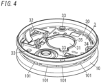
- the partition 3 partitions the inside of the housing 1 in the up-down directions. More specifically, as shown in FIG. 2 , the partition 3 divides the inside of the housing 1 into: a first space interposed between the first cover 11 and the partition 3; and a second space interposed between the second cover 12 and the partition 3 in the up-down directions. As shown in FIGS. 3 and 4 , the partition 3 includes a body portion 30 that has a first through hole 31, a second through hole 32, a plurality (three in this embodiment) of first insertion holes 33, a second insertion hole 34, and a protrusion 35.
- the body portion 30 is a disk-shaped member.
- the first through hole 31 penetrates the body portion 30 in the thickness direction (the up-down directions) and has a generally circular shape similar to an outer shape of a detection cover 21 (described later) of the detection block 2 in planar view.
- the detection cover 21 of the detection block 2 is inserted into the first through hole 31 from below.
- the second through hole 32 penetrates the body portion 30 in the thickness direction (the up-down directions) and has a generally circular shape similar to an outer shape of a battery case 114 (described later) of the first cover 11 in planar view.
- the battery case 114 of the first cover 11 is inserted into the second through hole 32 from below.
- the plurality of first insertion holes 33 and the second insertion hole 34 penetrate the body portion 30 in the thickness direction (the up-down directions) and have circular shapes in planar view.
- Each of the plurality of first insertion holes 33 faces a corresponding first boss 111 (described later) of the first cover 11 and a corresponding screw hole 121 (described later) of the second cover 12, while the first cover 11 and the second cover 12 are combined with the main body 10.
- the second insertion hole 34 faces a second boss 112 (described later) of the first cover 11 and a through hole 42 (described later) of the board 41, while the first cover 11 and the second cover 12 are combined with the main body 10.
- the protrusion 35 protrudes downward from a lower surface of the body portion 30.
- the protrusion 35 is provided along a peripheral edge of the first through hole 31.
- the dimension of the protrusion 35 in the up-down directions is 1.2 mm.
- the dimension of the protrusion 35 in the up-down directions is not required to be exactly 1.2 mm, and an error of ⁇ 0.05 mm may be allowed.
- the first cover 11 has a disk shape that is circular in planar view, and has an outer circumferential shape similar to that of the main body 10 in planar view.
- the first cover 11 includes a plurality (three in this embodiment) of first bosses 111, a second boss 112, an acoustic case 113, and a battery case 114.
- the board 41 is disposed in a region surrounded by the plurality of first bosses 111 and the second boss 112, of the first cover 11.
- Each of the plurality of first bosses 111 has a cylinder, and is provided integrally with the first cover 11 so as to project upwardly from an upper surface of the first cover 11.
- Each of the plurality of first bosses 111 has a screw hole into which a corresponding first screw 91 of the three first screws 91 is screwed.
- the second boss 112 has a tubular body that is circular in planar view and is provided integrally with the first cover 11 so as to project upwardly from the upper surface of the first cover 11.
- the second boss 112 has a screw hole into which the second screw 92 is screwed.
- the acoustic case 113 has a cylindrical body, and is provided integrally with the first cover 11 so as to project upwardly from the upper surface of the first cover 11.
- the sound output unit 94 is housed in the acoustic case 113.
- the acoustic case 113 has a sound hole that is disposed in a bottom surface of the acoustic case 113 and penetrates the first cover 11 in the thickness direction (the up-down directions).
- the sound output unit 94 outputs a sound to the outside through the sound hole.
- the sound hole is covered with a decorative plate disposed on a lower surface of the first cover 11.
- the battery case 114 has a rectangular body-shaped box, and is provided integrally with the first cover 11 so as to project upwardly from the upper surface of the first cover 11.
- the battery case 114 houses therein the battery B1 that functions as a power source for operation of the smoke sensor 100.
- the battery B1 may be a primary battery or a secondary battery.
- the second cover 12 has a disk-like shape that is circular in planar view, and has an outer circumferential shape similar to that of the main body 10 in planar view.
- the second cover 12 has a plurality (three in this embodiment) of screw holes 121.
- Each of the plurality of screw holes 121 has a circular shape in planar view and penetrates the second cover 12 in the thickness direction (the up-down directions).
- a corresponding first screw 91 of the three first screws 91 is inserted from above the second cover 12.
- the housing 1 is assembled as follows. First, the first cover 11 is combined with the main body 10 so as to close the upper opening in the main body 10. The second cover 12 is then combined with the main body 10 so as to close the lower opening in the main body 10. The plurality of first insertion holes 33 of the partition 3, the plurality of first bosses 111 of the first cover 11, and the plurality of screw holes 121 of the second cover 12 are then superimposed on each other. In this state, each of the plurality of first screws 91 is inserted and fastened into a corresponding screw hole 121 from above the second cover 12, thereby the main body 10, the first cover 11, and the second cover 12 being coupled to one another.
- the detection block 2 includes a detecting unit 20 and a detection cover 21 as shown in FIG. 3 .
- the detection cover 21 houses therein the detecting unit 20.
- the detection cover 21 has a tubular shape with bottom, and includes a bottom wall 211 and a peripheral wall 212.
- the bottom wall 211 is a plate member that has a generally circular shape in planar view. That is to say, the detection cover 21 has a cylindrical shape with bottom.
- the peripheral wall 212 is provided to project downwardly from a peripheral edge of the bottom wall 211.
- the detection space Sp1 is a space formed by the board 41 and the detection cover 21 in the inside of the housing 1.
- the detection space Sp1 is a space surrounded by the board 41 and the detection cover 21 in the inside of the housing 1.
- the detecting unit 20 is configured to detect the smoke in the detection space Sp1.
- the detecting unit 20 includes a light emitting part 201 and a light receiving part 202, and is photoelectric.
- the "photoelectric" mentioned in this disclosure means a method of sensing the smoke based on a change in the amount of light reflected by the smoke particles in the detection space Sp1, or the amount of light transmitted through the detection space Sp1, using the light emitting part 201 and the light receiving part 202.
- the light emitting part 201 emits light toward the detection space Sp1.
- the light receiving part 202 is disposed at a position not to receive direct light from the light emitting part 201 but to receive scattered light by the smoke particles in the detection space Sp1.
- the light receiving part 202 does not receive the light emitted from the light emitting part 201, but in a state in which the smoke is present in the detection space Sp1, the light receiving part 202 can receive light (i.e., scattered light) emitted from the light emitting part 201 and scattered by the smoke particles. Accordingly, the smoke sensor 100 can sense the smoke being present in the detection space Sp1 in response to the state of light reception of the light receiving part 202.
- the amount of light received by the light receiving part 202 may change depending on, for example, a concentration of the smoke in the detection space Sp1 or a type of the smoke (white smoke, black smoke, or any other smoke).
- the light receiving part 202 outputs, to the circuit block 4, an output signal corresponding to the amount of light received.
- the smoke sensor 100 further includes a flange 22 projecting from a peripheral edge of an end of the detection cover 21.
- the flange 22 is disposed between the partition 3 and the board 41 in a thickness direction D1 (up-down directions) of the board 41.
- the smoke sensor 100 further includes the flange 22 projecting from the peripheral edge of the end of the detection cover 21 between the protrusion 35 of the partition 3 and the board 41 in the thickness direction D1 of the board 41.
- the smoke sensor 100 further includes the flange 22 projecting from the peripheral edge of the end of the detection cover 21 so as to be positioned between the protrusion 35 of the partition 3 and the board 41 in the thickness direction D1 of the board 41.
- FIG. 5 is an enlarged view of a part of a cross-section shown in FIG. 2 .
- the "end of the detection cover 21" mentioned herein is an end, which is not connected to the bottom wall 211, of both ends of the peripheral wall 212 in the up-down directions (i.e., a lower end of the peripheral wall 212).
- the flange 22 is provided along the entire peripheral edge of the lower end of the peripheral wall 212. That is to say, the flange 22 has a generally circular ring shape in planar view.
- the cross-section of the flange 22 taken along the up-down directions has a rectangular shape.
- the flange 22 according to the first embodiment is disposed to project outward from the peripheral edge of the end of the detection cover 21.
- the flange 22 is disposed to project outward from a peripheral edge of a lower end of the peripheral wall 212 of the detection cover 21.
- the "projecting outward” mentioned herein means projecting, in the thickness direction (radial direction) of the peripheral wall 212, toward a direction away from the bottom wall 211 (i.e., toward a direction closer to the main body 10 (refer to FIG. 2 )). That is to say, in the first embodiment, the flange 22 and the bottom wall 211 are disposed not to overlap with each other in planar view. In other words, the flange 22 is disposed not to fit within a projection plane of the bottom wall 211 in the up-down directions. According to this configuration, the smoke sensor 100 has an advantage that the partition 3 can more stably hold the flange 22.
- the flange 22 has a first surface 221 and a second surface 222, which face each other along the thickness direction D1 of the board 41.
- the first surface 221 is a lower surface of the flange 22, and the second surface 222 is an upper surface of the flange 22.
- the first surface 221 is in contact with the board 41. More specifically, the first surface 221 is certainly in contact with the upper surface of the board 41 so as to press against the upper surface by a sufficient force.
- the second surface 222 is in contact with the partition 3. More specifically, the lower surface of the protrusion 35 of the partition 3 is certainly in contact with the second surface 222 so as to press against the second surface 222 by a sufficient force.
- the detection cover 21 includes a plurality of window holes 213 disposed in the peripheral wall 212, through which the smoke flows into the detection cover 21 (i.e., the detection space Sp1). Accordingly, the smoke is allowed to flow into the detection space Sp1 from the outside of the detection cover 21 through any of the plurality of window holes 213.
- Each of the plurality of window holes 213 has a rectangular shape in front view and penetrates the peripheral wall 212 in the thickness direction (i.e., the radial direction) thereof.
- the detection cover 21 further includes a plurality of insect nets 93 covering the plurality of window holes 213, as shown in FIGS. 2 and 3 .
- Each of the plurality of insect nets 93 has a rectangular shape in front view.
- the plurality of insect nets 93 are attached to the peripheral wall 212 to cover the plurality of window holes 213 within the detection cover 21. In this embodiment, all of the plurality of window holes 213 are covered with the plurality (two in this embodiment) of insect nets 93.
- Each insect net 93 has a number of rectangular meshes, as shown in FIG. 3 .
- the detection block 2 further includes a labyrinth structure 23 that is disposed inside the detection cover 21, as shown in FIG. 2 .
- the labyrinth structure 23 is implemented as an aggregate of a plurality of small pieces circularly arranged in the detection cover 21 to surround the detection space Sp1 in the circumferential direction of the detection cover 21.
- the labyrinth structure 23 allows the smoke to enter the detection space Sp1 through gaps between the plurality of small pieces from the outside of the detection cover 21 and to be entrapped in the detection space Sp1.
- the labyrinth structure 23, as shown in FIG. 5 has insertion portions 231 which are respectively inserted into insertion holes 411 provided in the board 41.
- the labyrinth structure 23 is fixed to the board 41 by the insertion portions 231 being inserted into the insertion holes 411.
- the circuit block 4 includes the board 41 and a plurality of electronic components including a switch(es).
- the plurality of electronic components are mounted on the board 41.
- the board 41 is, for example, a printed wiring board including a patterned conductor.
- the detecting unit 20 of the detection block 2 is electrically connected to the patterned conductor of the board 41.
- the sound output unit 94 and the battery B1 are also electrically connected to the patterned conductor of the board 41.
- the board 41 is disposed below the detection block 2 (i.e., between the detection block 2 and the first cover 11), as shown in FIG. 2 .
- the detection block 2 is disposed on one surface (upper surface) of both surfaces in the thickness direction D1, of the board 41. That is to say, the detecting unit 20 and the detection cover 21 are disposed on the one surface in the thickness direction D1, of the board 41. In other words, the detecting unit 20 and the detection cover 21 are mounted on the one surface in the thickness direction D1, of the board 41.
- the board 41 has a through hole 42.
- the through hole 42 penetrates the board 41 in the thickness direction (up-down directions) and has a circular shape in planar view.
- the upper end of the second boss 112 of the first cover 11 is inserted into the through hole 42.
- the second insertion hole 34 of the partition 3 and the second boss 112 of the first cover 11 are superimposed on each other, and the second screw 92 is inserted and fastened into the second insertion hole 34 from above, thereby the board 41 being held between the partition 3 and the first cover 11.
- the board 41 is held between the partition 3 and the first cover 11 in a state where the flange 22 provided to the detection cover 21 is disposed between the board 41 and the partition 3.
- the partition 3 holds the flange 22 to press the flange 22 against the board 41.
- the circuit block 4 further includes an antenna 43. While the shaft part of the second screw 92 is inserted into one end of the antenna 43, the second screw 92 is inserted and fastened in the through hole 42 of the first embodiment from above with the upper end of the second boss 112 of the first cover 11 being inserted in the through hole 42. Thus, the antenna 43 is fixed to the board 41 in electrical connection to the patterned conductor of the board 41.
- the antenna 43 is a part of a communication module mounted on the board 41.
- the communication module is configured to communicate wirelessly with another device (e.g., another smoke sensor, etc.).
- the circuit block 4 includes a control circuit constituted by the plurality of electronic components.
- the control circuit is configured to control the light emitting part 201, the light receiving part 202, the sound output unit 94, and any other units.
- the control circuit at least drives the light emitting part 201 and performs signal processing on the output signal of the light receiving part 202.
- the circuit block 4 compares the amount of light received by the light receiving part 202 (e.g., the magnitude of the output signal) with a threshold value to determine whether or not smoke is present in the detection space Sp1.
- the circuit block 4 determines that smoke with a concentration equal to or more than a certain level is present in the detection space Sp1.
- the circuit block 4 outputs, to the sound output unit 94, an electrical signal for driving the sound output unit 94 in response to the determination that the smoke with the concentration equal to or more than the certain level is present in the detection space Sp1.
- the sound output unit 94 is configured to output a sound (sound wave) in response to reception of the electrical signal from the circuit block 4. That is to say, the smoke sensor 100 makes the sound output unit 94 output the sound, when finding that the amount of light received by the light receiving part 202 is equal to or more than the threshold value.
- the sound output unit 94 is implemented as a speaker, a buzzer, or the like, which converts an electrical signal to the sound.
- the sound output unit 94 is generally disk-shaped with a circular shape in planar view.
- the flange 22 projects from the peripheral edge of the lower end of the peripheral wall 212 of the detection cover 21, and is disposed between the protrusion 35 of the partition 3 and the board 41 in the thickness direction D1 (the up-down directions) of the board 41.
- the first surface 221 of the flange 22 is in contact with the board 41, and the second surface 222 is in contact with the partition 3.
- the flange 22 is pressed against the board 41 by the partition 3, and can suppress generation of a gap between the protrusion 35 of the detection cover 21 and the board 41.
- the flange 22 can prevent the foreign matter from entering the detection space Sp1 from the gap between the detection cover 21 and the board 41.
- the suppressor 5 according to the first embodiment includes the flange 22. More specifically, the suppressor 5 according to the first embodiment is implemented as the flange 22.
- the smoke sensor 100 can reduce the chance that the foreign matter enters the detection space Sp1 from the outside without the smoke sensor 100 having the complicated internal structure. Accordingly, the smoke sensor 100 can contribute to reducing the chance of the false detection due to the foreign matter without the smoke sensor 100 having the complicated internal structure.
- the protrusion 35 is disposed to protrude downward from the lower surface of the main body 10.
- the partition 3 can more strongly press the flange 22 provided to the detection cover 21 against the board 41.
- the flange 22 can prevent the gap from being generated between the detection cover 21 and the board 41.
- the occurrence of intervals can be more inhibited.
- the flange 22 can further reduce the chance that the foreign matter enters the detection space Sp1 from the gap between the detection cover 21 and the board 41. Accordingly, the smoke sensor 100 can contribute to further reducing the chance of the false detection due to the foreign matter.
- the first embodiment described above is merely one of various exemplary embodiments of the present disclosure.
- the first embodiment described above may be readily modified in various manners depending on the design or any other factor, as long as the purpose of the present disclosure can be achieved.
- Each of the following variations may be implemented in combination with the other variation as appropriate.
- FIG. 6 shows a schematic cross-sectional view of an essential part of a smoke sensor 100a according to the first variation.
- the smoke sensor 100a includes a flange 22a that projects from a peripheral edge of a lower end of a peripheral wall 212 of a detection cover 21 and is disposed between a protrusion 35 of a partition 3 and a board 41 in a thickness direction D1 (up-down directions) of the board 41.
- the flange 22a projects outward to be curved downwardly from the peripheral edge of the lower end of the peripheral wall 212.
- the "outward” mentioned herein is a direction away from a bottom wall 211 in the thickness direction (radial direction) of the peripheral wall 212.
- the flange 22a has a first end 223a and a second end 224a as a pair of ends facing each other along the projecting direction of the flange 22a.
- the flange 22a projects outward while being curved downwardly such that the second end 224a is closer to the board 41 than the first end 223a is (in other words, the second end 224a is positioned below the first end 223a).
- the "first end 223a” mentioned herein is one end, which is connected to the lower end of the peripheral wall 212 of the detection cover 21, of the paired ends facing each other along the projecting direction.
- the "second end 224a” mentioned herein is the other end, which is different from the first end 223a, of the paired ends facing each other along the projecting direction. That is to say, the "second end 224a" is a tip end of the flange 22a.
- the flange 22a has a first surface 221a and a second surface 222a facing each other along the thickness direction D1 of the board 41.
- the first surface 221a is partially in contact with the board 41. More specifically, as shown in FIG. 6 , the first surface 221a includes a first region on the side of the first end 223a and a second region on the second end 224a, and the first region is separated from the board 41, but the second region is in contact with the board 41 so as to press against the board 41 by a sufficient force.
- the second surface 222a is in contact with the partition 3. In other words, the lower surface of the protrusion 35 of the partition 3 is in contact with a certain region of the second surface 222a on the side of the second end 224a so as to press against the certain region by a sufficient force.
- the flange 22a Since the detection cover 21 is mounted to the board 41 while being pressed downwardly, the flange 22a curved is deflected. As a result, the flange 22a has an elastic force to press at least a part of the first surface 221a against the board 41. More specifically, the flange 22a has an elastic force to press the second region on the side of the second end 224a, of the first surface 221a, against the board 41.
- the flange 22a is pressed against the board 41 by the partition 3, and furthermore, the flange 22a can be more certainly in contact with the board 41 by the elastic force (in other words, the adhesion between the flange 22a and the board 41 can be improved), which can further reduce the chance that the foreign matter enters the detection space Sp1 from the outside. Therefore, the smoke sensor 100a can contribute to further reducing the chance of the false detection due to the foreign matter.
- FIG. 7A shows a schematic cross-sectional view of an essential part of a smoke sensor 100b according to the second variation.
- the smoke sensor 100b includes a flange 22b that projects from a peripheral edge of a lower end of a peripheral wall 212 of a detection cover 21 and is disposed between a protrusion 35 of a partition 3 and a board 41 in a thickness direction D1 (up-down directions) of the board 41.
- the flange 22b has a generally circular ring shape in planar view and has a first surface 221b and a second surface 222, which face each other along the thickness direction D1 of the board 41.
- the flange 22b of the smoke sensor 100b includes an uneven part 24 provided in the whole of the first surface 221b.
- the uneven part 24 includes a plurality of annular-shaped protrusions 241 that protrude downward from the first surface 221b and are provided with approximately equal intervals along a radial direction of the flange 22b.
- the cross-section of each of the plurality of protrusions 241, taken along the up-down directions, has an inverted triangular shape.
- the uneven part 24 may include a plurality of conical-shaped protrusions that protrude downward from the first surface 221b and are provided with approximately equal intervals along the circumferential direction and the radial direction of the flange 22b.
- the flange 22b can be more certainly in contact with the board 41 (in other words, the adhesion between the flange 22b and the board 41 can be improved).
- the flange 22b can further reduce the chance that the foreign matter enters the detection space Sp1 from the outside.
- the smoke sensor 100b can contribute to further reducing the chance of the false detection due to the foreign matter.
- the external force applied from the flange 22b to the board 41 can be dispersed, and therefore, the smoke sensor 100b can buffer the stress generated at the board 41.
- the uneven part 24 is disposed in the whole of the first surface 221b of the flange 22b but may be disposed in a part of the first surface 221b. That is to say, the uneven part 24 may be disposed in at least a part of the first surface 221b.
- an uneven part 24 may be disposed in a second surface 222c of a flange 22c.
- the external force applied from a protrusion 35 of a partition 3 to the flange 22c can be dispersed, so that the external force applied from the flange 22c to a board 41 can be also dispersed.
- the smoke sensor 100c can buffer the stress generated at the board 41.
- FIG. 8A shows a schematic cross-sectional view of an essential part of a smoke sensor 100d according to the third variation.
- the smoke sensor 100d includes a flange 22d that projects from a peripheral edge of a lower end of a peripheral wall 212 of a detection cover 21 and is disposed between a protrusion 35 of a partition 3 and a board 41 in a thickness direction D1 (up-down directions) of the board 41.
- the flange 22d has a generally circular ring shape in planar view and has a first surface 221 and a second surface 222d, which face each other along the thickness direction D1 of the board 41.
- the smoke sensor 100d includes a resin part 61 as a buffer member 6.
- the resin part 61 is disposed between a second surface 222d of the flange 22d and the partition 3.
- the partition 3 is disposed to indirectly press the flange 22d against the board 41 through the buffer member 6 (resin part 61). That is to say, the second surface 222d of the flange 22d is not in directly contact with the partition 3, but in indirectly contact with the partition 3 through the buffer member 6.
- the buffer member 6 can buffer an external force applied from the partition 3 to the flange 22d, and can also therefore buffer an external force applied from the flange 22d to the board 41.
- the smoke sensor 100d can also contribute to reducing the stress generated at the board 41.
- the resin part 61 may be made of, for example, silicone or urethane. Alternatively, the resin part 61 may be made of photo-curable resin such as UV photon resin. Note that, the material of the resin part 61 is not limited in particular, as long as the resin part 61 can be disposed between the second surface 222d of the flange 22d and the partition 3.
- the second surface 222d of the flange 22d which is in contact with the resin part 61, is a rough surface.
- the "rough surface” mentioned herein may be, for example, a surface in which irregularities are provided, or a surface of which surface state is changed by plasma treatment or any other treatment. According to this configuration, providing the rough surface can increase the surface area of the flange 22d which is in contact with the resin part 61, and the flange 22d can therefore obtain a physical adhesive effect. That is to say, the smoke sensor 100d can also contribute to improving the adhesion between the flange 22d and the resin part 61.
- a smoke sensor 100e may include a packing member 62 as the buffer member 6.
- the packing member 62 is made of a rubber material such as a fluorine rubber or a silicone rubber. Note that, the material of the packing member 62 is not limited in particular, as long as the packing member 62 can close the gap between the second surface 222d of the flange 22d and the partition 3.
- a smoke sensor 100f may include a brush-shaped member 63 as the buffer member 6.
- the brush-shaped member 63 is implemented as an aggregate of hairs growing upwardly from the second surface 222d of the flange 22d.
- the brush-shaped member 63 is made of synthetic fibers such as polypropylene or nylon.
- the brush-shaped member 63 may be made of vegetable fibers, animal fibers, or metal fibers. Note that, the material of the brush-shaped member 63 is not limited in particular, as long as the brush-shaped member 63 can close the gap between the second surface 222d of the flange 22d and the partition 3.
- the flange 22 is disposed to project outward from the peripheral edge of the lower end of the peripheral wall 212 of the detection cover 21, but may be disposed to project inward.
- the "projecting inward” mentioned herein means projecting toward a direction away from the main body 10 in the thickness direction (the radial direction) of the peripheral wall 212. That is to say, the flange 22 and the bottom wall 211 may be disposed so as to overlap with each other in planar view. In other words, the flange 22 may be disposed to be within a projection plane of the bottom wall 211 in the up-down directions.
- the main body 10 includes the plurality of openings 101 arranged in the circumferential direction, but should not be construed as limiting.
- the main body 10 may include at least one opening 101. That is to say, a single opening 101 may be provided in the main body 10 to be arranged in the circumferential direction.
- the partition 3 according to the first embodiment described above includes the protrusion 35, but may not include the protrusion 35.
- the bottom wall 211 of the detection cover 21 is a plate member that has a generally circular shape in planar view, but may be a plate member that has a polygonal shape in planar view. That is to say, the detection cover 21 may have a tubular shape with bottom, which is polygonal-shaped in planar view.
- the detection cover 21 includes the plurality of window holes 213 in the peripheral wall 212, but should not be construed as limiting.
- the detection cover 21 may include at least one window hole 213. That is to say, the detection cover 21 may include a single window hole 213 disposed in the peripheral wall 212.
- a smoke sensor 100g according to the second embodiment will be described with reference to FIG. 9A .
- elements similar to those of the first embodiment are assigned with same reference signs, and the explanations thereof are appropriately omitted.
- the smoke sensor 100g according to the second embodiment is different from the smoke sensor 100 according to the first embodiment in that the smoke sensor 100g includes a resin part 7.
- the smoke sensor 100g according to the second embodiment is different from the smoke sensor 100 according to the first embodiment in that a suppressor 5a of the smoke sensor 100g includes a flange 22g and the resin part 7.
- the smoke sensor 100g includes the flange 22g provided to a detection cover 21, similarly to that of the first embodiment.
- the flange 22g projects outward from the whole of the peripheral edge of the end of the detection cover 21.
- the flange 22g has a first surface 221g and a second surface 222, which face along a thickness direction D1 of a board 41.
- the first surface 221g is a lower surface of the flange 22g and the second surface 222 is an upper surface of the flange 22g.
- the first surface 221g according to the second embodiment is different from the first surface 221 according to the first embodiment in that the first surface 221g is not in contact with the board 41.
- a space is provided between the first surface 221g of the flange 22g and an upper surface of the board 41 in the thickness direction D1 of the board 41.
- the second surface 222 according to the second embodiment is in contact with the partition 3, similarly to the second surface 222 according to the first embodiment. More specifically, a lower surface of a protrusion 35 of the partition 3 is certainly in contact with the second surface 222 so as to press against the second surface 222 by a sufficient force.
- the smoke sensor 100g includes the resin part 7.
- the resin part 7 is disposed to be in contact with both the flange 22g and the board 41. More specifically, the resin part 7 is in contact with both an end surface 225g of the flange 22g and the upper surface of the board 41.
- the "end surface 225g of the flange 22g" mentioned herein is an end surface, which is different from an end surface connected to the detection cover 21 (peripheral wall 212), of paired end surfaces facing each other along a projecting direction of the flange 22g. That is to say, the "end surface 225g of the flange 22g" is a tip end surface of the flange 22g.
- the flange 22g and the resin part 7 are disposed to close the gap between the detection cover 21 and the board 41.
- the flange 22g and the resin part 7 suppress a foreign matter from entering the detection space Sp1 through the gap between the detection cover 21 and the board 41. That is to say, the suppressor 5a according to the second embodiment includes the flange 22g and the resin part 7. In other words, the suppressor 5a according to the second embodiment further includes the resin part 7 in addition to the flange 22g. More specifically, the suppressor 5a according to the second embodiment is configured by the flange 22g and the resin part 7. According to this configuration, the smoke sensor 100g can further suppress the chance that the gap is generated between the flange 22g and the board 41.
- the smoke sensor 100g has an effect of further suppressing the foreign matter from entering the detection space Sp1 from the outside. Therefore, the smoke sensor 100g can contribute to reducing a chance of a false detection due to the foreign matter. Furthermore, the smoke sensor 100g has an advantage that the resin part 7 can buffer the external force applied to the board 41 from the flange 22g, and also reduce the stress generated at the board 41.
- the resin part 7 is made of, for example, silicone or urethane.
- the resin part 7 may be made of photo-curable resin such as UV photon resin.
- the material of the resin part 7 is not limited in particular, as long as the resin part 7 can be disposed to be in contact with both the flange 22g and the board 41.
- the end surface 222g of the flange 22g which is a surface in contact with the resin part 7, is a rough surface.
- the "rough surface” mentioned herein may be, for example, a surface in which irregularities are provided, or a surface of which surface state is changed by plasma treatment or any other treatment. According to this configuration, providing the rough surface can increase the surface area of the end surface 222g which is in contact with the resin part 7, and the flange 22g can therefore obtain a physical adhesive effect. That is to say, the smoke sensor 100g can also contribute to improving the adhesion between the flange 22g and the resin part 7.
- the second embodiment described above is merely one of various exemplary embodiments of the present disclosure.
- the second embodiment described above may be readily modified in various manners depending on the design or any other factor, as long as the purpose of the present disclosure can be achieved.
- Each of the following variations may be implemented in combination with the other variation as appropriate.
- the resin part 7 is disposed to be in contact with both the end surface 225g of the flange 22g and the upper surface of the board 41.
- a resin part 7a of a smoke sensor 100h may be disposed to be in contact with both a first surface 221h of a flange 22h and an upper surface of a board 41. That is to say, the position of the resin part 7a is not limited in particular, as long as the flange 22h and the resin part 7a are disposed to close the gap between the detection cover 21 and the board 41.
- the first surface 221h is partially in contact with the resin part 7a.
- the whole of the first surface 221h may be in contact with the resin part 7a.
- the first surface 221h of the flange 22h which is a surface in contact with the resin part 7a, is a rough surface. More specifically, the whole of the first surface 221h of the flange 22h (including not only a region in contact with the resin part 7a but also a region not in contact with the resin part 7a) is the rough surface. Note that, at least a part, which is in contact with the resin part 7a, of the first surface 221h may have the rough surface.
- a smoke sensor 100i according to the third embodiment will be described with reference to FIG. 10A .
- elements similar to those of the first embodiment are assigned with same reference signs, and the explanations thereof are appropriately omitted.
- the smoke sensor 100i according to the third embodiment is different from the smoke sensor 100 according to the first embodiment in that the smoke sensor 100i includes a blocking part 8.
- the smoke sensor 100i according to the third embodiment is different from the smoke sensor 100 according to the first embodiment in that a suppressor 5c of the smoke sensor 100i includes a flange 22i and the blocking part 8.
- the smoke sensor 100i includes the flange 22i provided to a detection cover 21, similarly to that of the first embodiment.
- the flange 22i projects outward from the whole of the peripheral edge of the end of the detection cover 21.
- the flange 22i has a first surface 221i and a second surface 222, which face along a thickness direction D1 of a board 41.
- the first surface 221i is a lower surface of the flange 22i and the second surface 222 is an upper surface of the flange 22i.
- the first surface 221i according to the third embodiment is different from the first surface 221 according to the first embodiment in that the first surface 221i is not in contact with the board 41.
- a space is provided between the first surface 221i of the flange 22i and an upper surface of the board 41 in the thickness direction D1 of the board 41.
- the second surface 222 according to the third embodiment is in contact with the partition 3, similarly to the second surface 222 according to the first embodiment. More specifically, a lower surface of a protrusion 35 of the partition 3 is certainly in contact with the second surface 222 so as to press against the second surface 222 by a sufficient force.
- the smoke sensor 100i according to the third embodiment includes the blocking part 8.
- the blocking part 8 is disposed to close the gap between the flange 22i and the board 41. More specifically, the blocking part 8 is disposed to close the gap between the first surface 221i of the flange 22i and the upper surface of the board 41.
- the blocking part 8 according to the third embodiment is a packing member 81 provided on the first surface 221i of the flange 22i. Since the flange 22i has a generally circular ring shape in planar view, the packing member 81 is also implemented as a member with a generally circular ring shape in planar view.
- the cross-sectional shape of the packing member 81 is a substantially inversely triangular shape, and the lower end of the packing member 81 is crushed against the board 41, which can more tightly close the gap between the flange 22i and the board 41.
- the packing member 81 is made of a rubber material such as a fluorine rubber or a silicone rubber. Note that, the material of the packing member 81 is not limited in particular, as long as the packing member 81 can close the gap between the flange 22i and the board 41.
- the flange 22i and the blocking part 8 suppress a foreign matter from entering the detection space Sp1 from the gap between the detection cover 21 and the board 41. That is to say, the suppressor 5c according to the third embodiment includes the flange 22i and the blocking part 8. In other words, the suppressor 5c according to the third embodiment further includes the blocking part 8 in addition to the flange 22i. According to this configuration, the blocking part 8 can reduce an external force applied to the board 41 from the flange 22i. Therefore, the smoke sensor 100i has an effect of further suppressing the foreign matter from entering the detection space Sp1 from the outside, while further reducing the stress generated at the board 41. Therefore, the smoke sensor 100i can contribute to reducing a chance of a false detection due to the foreign matter.
- the third embodiment described above is merely one of various exemplary embodiments of the present disclosure.
- the third embodiment described above may be readily modified in various manners depending on the design or any other factor, as long as the purpose of the present disclosure can be achieved.
- Each of the following variations may be implemented in combination with the other variation as appropriate.
- the blocking part 8 is implemented as the packing member 81, but may be implemented as a brush-shaped member 82, as shown in FIG. 10B .
- the brush-shaped member 82 is disposed on a first surface 221j of a flange 22j. More specifically, the brush-shaped member 82 is implemented as an aggregate of hairs growing downwardly from the first surface 221j of the flange 22j.
- the brush-shaped member 82 is made of synthetic fibers such as polypropylene or nylon.
- the brush-shaped member 82 may be made of vegetable fibers, animal fibers, or metal fibers. Note that, the material of the brush-shaped member 82 is not limited in particular, as long as the brush-shaped member 82 can close the gap between the flange 22j and the board 41.
- a suppressor 5d with the configuration shown in FIG. 10B includes the flange 22j and the brush-shaped member 82.
- the suppressor 5d further includes the brush-shaped member 82 in addition to the flange 22j.
- the blocking part 8 may be implemented as an adhesive tape 83, as shown in FIG. 10C .
- the adhesive tape 83 is attached to the upper surface of the board 41. More specifically, the adhesive tape 83 is attached to the upper surface of the board 41 so as to have a generally circular ring shape in planar view.
- the adhesive tape 83 and a flange 22k are disposed to overlap with each other in planar view. In other words, the adhesive tape 83 is disposed to be within a projection plane of the flange 22k in the up-down directions.
- the adhesive tape 83 has an upper surface with adhesiveness. Therefore, the adhesive tape 83 can catch the foreign matter, which passes through the gap between the flange 22k and the adhesive tape 83, on the upper surface with adhesiveness.
- a suppressor 5e with the configuration shown in FIG. 10C includes the flange 22k and the adhesive tape 83.
- the suppressor 5e further includes the adhesive tape 83 in addition to the flange 22k.
- the blocking part 8 may include at least one of the packing member 81, the brush-shaped member 82, and the adhesive tape 83. According to this configuration, the blocking part 8 can reduce the external force applied to the board 41 from the flange (22i-22k), and can also reduce the stress generated at the board 41.
- a smoke sensor (100, 100a-100k) includes a housing (1), a detecting unit (20), a partition (3), a board (41), a detection cover (21) having a tubular shape with bottom, and a suppressor (5, 5a-5e).
- the housing (1) has an opening (101) through which smoke flows into the housing (1) from an outside of the housing (1).
- the detecting unit (20) is configured to detect the smoke in a detection space (Sp1) provided in an inside of the housing (1).
- the partition (3) is configured to divide the inside of the housing (1).
- the detecting unit (20) is disposed on the board (41).
- the detection cover (21) is configured to house the detecting unit (20).
- the suppressor (5, 5a-5e) is disposed at a peripheral edge of an end of the detection cover (21), and configured to suppress a foreign matter from entering the detection space (Sp1) from the outside.
- the detection space (Sp1) is a space formed by the board (41) and the detection cover (21).
- the suppressor (5, 5a-5e) is disposed between the board (41) and the partition (3).
- the suppressor (5, 5a-5e) is at least partially in contact with the board (41).
- the smoke sensor (100, 100a-100k) can contribute to reducing the chance of a false detection due to a foreign matter.
- the detection cover (21) includes: a window hole (213) through which the smoke flows into the detection cover (21); and an insect net (93) disposed to cover the window hole (213).
- the smoke sensor (100, 100a-100k) can contribute to sensing the smoke more efficiently.
- a smoke sensor (100, 100a-100k) according to a third aspect, which may be implemented in conjunction with the first or second aspect, further includes a flange (22, 22a-22k).
- the flange (22, 22a-22k) projects from the peripheral edge of the end of the detection cover (21), the flange (22, 22a-22k) being disposed between the partition (3) and the board (41) in a thickness direction (D1) of the board (41).
- the suppressor (5, 5a-5e) includes the flange (22, 22a-22k).
- the smoke sensor (100, 100a-100k) can contribute to reducing the chance of the false detection due to the foreign matter.
- a smoke sensor (100, 100a-100k) according to a fourth aspect, which may be implemented in conjunction with the third aspect, the flange (22, 22a-22k) is disposed to project outward.
- the smoke sensor (100, 100a-100k) has the advantage that the partition (3) can more stably hold the flange (22, 22a-22k).
- the flange (22, 22a-22f) has a first surface (221, 221a, 221b) and a second surface (222), which face each other along the thickness direction (D1).
- the first surface (221, 221a, 221b) is in contact with the board (41).
- the smoke sensor (100, 100a-100f) can contribute to reducing the chance of the false detection due to the foreign matter without the smoke sensor (100, 100a-100f) having a complicated internal structure.
- the flange (22a) has an elastic force to press at least a part of the first surface (221a) against the board (41).
- the flange (22a) can be more certainly in contact with the board (41), and the smoke sensor (100a) can further reduce the chance of the false detection due to the foreign matter.
- the first surface (221b) includes an uneven part (24) that is disposed in at least a part of the first surface (221b).
- the flange (22b) can be more certainly in contact with the board (41), and the smoke sensor (100b) can further reduce the chance of the false detection due to the foreign matter. Furthermore, the smoke sensor (100b) can buffer the stress generated at the board (41).
- the suppressor (5a, 5b) further includes a resin part (7, 7a).
- the resin part (7, 7a) is disposed to be in contact with both of the flange (22g, 22h) and the board (41).
- the smoke sensor (100g, 100h) can contribute to further suppressing the foreign matter from entering the detection space (Sp1) from the outside. Furthermore, the smoke sensor (100g, 100h) can buffer the stress generated at the board (41).
- the flange (22g, 22h) has a rough surface, as a surface that is in contact with the resin part (7, 7a).
- the smoke sensor (100g, 100h) has the advantage that the flange (22g, 22h) can be more certainly in contact with the resin part (7, 7a).
- the suppressor (5c-5e) further includes a blocking part (8).
- the blocking part (8) is disposed to close a gap between the flange (22i-22k) and the board (41).
- the blocking part (8) is disposed to be in contact with the board (41).
- the smoke sensor (100i-100k) can contribute to further suppressing the foreign matter from entering the detection space (Sp1) from the outside, while reducing the stress generated at the board (41).
- the blocking part (8) includes at least one of a packing member (81), a brush-shaped member (82) and an adhesive tape (83).
- the smoke sensor (100i-100k) can contribute to further suppressing the foreign matter from entering the detection space (Sp1) from the outside, while reducing the stress generated at the board (41).
Landscapes
- Chemical & Material Sciences (AREA)
- Analytical Chemistry (AREA)
- Business, Economics & Management (AREA)
- Emergency Management (AREA)
- Physics & Mathematics (AREA)
- General Physics & Mathematics (AREA)
- Fire-Detection Mechanisms (AREA)
- Investigating Or Analysing Materials By Optical Means (AREA)
Abstract
Description
- The present disclosure generally relates to smoke sensors. More particularly, the present disclosure relates to a smoke sensor configured to detect smoke.
-
JP 2010-257258 A Document 1") discloses a smoke sensor. This smoke sensor includes a smoke sensing unit configured to optically detect smoke, using a light emitting part and a light receiving part. The smoke sensing unit further includes an optical base in which the light emitting part and the light receiving part are housed. The optical base is covered with an insect net. - In the smoke sensor disclosed in the
Document 1, a foreign matter may enter an inside (detection space) of the smoke sensor through a gap between the optical base (board) and a detection cover where the insect net is provided. For this reason, the smoke sensor has a problem that a false detection may occur due to the foreign matter entering the inside. - It is therefore an object of the present disclosure to provide a smoke sensor, which can contribute to reducing a chance of a false detection due to a foreign matter.
- A smoke sensor according to an aspect of the present disclosure includes a housing, a detecting unit, a partition, a board, a detection cover having a tubular shape with bottom, and a suppressor. The housing has an opening through which smoke flows into the housing from an outside of the housing. The detecting unit is configured to detect the smoke in a detection space provided in an inside of the housing. The partition is configured to divide the inside of the housing. On the board, the detecting unit is disposed. The detection cover is configured to house the detecting unit. The suppressor is disposed at a peripheral edge of an end of the detection cover and configured to suppress a foreign matter from entering the detection space from the outside. The detection space is a space formed by the board and the detection cover. The suppressor is disposed between the board and the partition. The suppressor is at least partially in contact with the board.
-
-
FIG. 1 is an appearance perspective view of a smoke sensor, when viewed from above, according to a first embodiment; -
FIG. 2 is a cross-sectional view of the smoke sensor; -
FIG. 3 is an exploded perspective view of the smoke sensor, when viewed from above; -
FIG. 4 is an appearance perspective view of a body portion of the smoke sensor, when viewed from below; -
FIG. 5 is a schematic cross-sectional view of an essential part of the smoke sensor; -
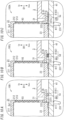
FIG. 6 is a schematic cross-sectional view of an essential part in a first variation of the smoke sensor; -
FIG. 7A is a schematic cross-sectional view of an essential part in a second variation of the smoke sensor; -
FIG. 7B is a schematic cross-sectional view of the essential part in the second variation of the smoke sensor; -
FIG. 8A is a schematic cross-sectional view of an essential part in a third variation of the smoke sensor; -
FIG. 8B is a schematic cross-sectional view of the essential part in the third variation of the smoke sensor; -
FIG. 8C is a schematic cross-sectional view of the essential part in the third variation of the smoke sensor; -
FIG. 9A is a schematic cross-sectional view of an essential part in a smoke sensor according to a second embodiment; -
FIG. 9B is a schematic cross-sectional view of an essential part in a variation of the smoke sensor; -
FIG. 10A is a schematic cross-sectional view of an essential part in a smoke sensor according to a third embodiment; -
FIG. 10B is a schematic cross-sectional view of an essential part in a variation of the smoke sensor; and -
FIG. 10C is a schematic cross-sectional view of the essential part in the variation of the smoke sensor. - A smoke sensor according to each of exemplary embodiments of the present disclosure will be described with reference to the drawings. The drawings to be referred to in the following embodiments are all schematic representations. That is to say, the ratio of the dimensions (including thicknesses) of respective constituent elements illustrated on the drawings does not always reflect their actual dimensional ratio.
- Hereinafter, an overview of a
smoke sensor 100 according to a first embodiment will be described with reference toFIGS. 1 to 3 . - The smoke sensor 100 (refer to
FIG. 1 ) according to the first embodiment is a disaster protection device that calls, when sensing smoke generated by a fire or any other event, an alert for the fire. That is to say, when the smoke is generated in response to occurrence of a disaster such as the fire, thesmoke sensor 100 senses the smoke and calls the alert, for example, by outputting an alarm sound or by interconnecting with another device, using a communication function. The "disaster protection device" mentioned in the present disclosure may be a device installed in a facility, for example, for the purpose of preventing the disaster such as the fire, preventing the spread of damage caused by the disaster, or recovering from the disaster. - The
smoke sensor 100 is installed and used in the facility. In the present embodiment, thesmoke sensor 100 is exemplified when used in a non-residential facility such as, for example, a hotel, an office building, a school building, a welfare facility, a commercial facility, a theme park, a hospital, or a factory. Of course, not limited to this example, thesmoke sensor 100 may be used in a facility such as a multi-family dwelling house or a single-family dwelling house. Thesmoke sensor 100 may be installed in the facility with being attached to a ceiling or a wall in a place such as a room, corridor or staircase, of the facility. - As shown in
FIGS 1 to 3 , thesmoke sensor 100 includes ahousing 1, a detectingunit 20, apartition 3, aboard 41, adetection cover 21 and asuppressor 5. - As shown in
FIG. 1 , thehousing 1 has anopening 101 through which smoke flows into thehousing 1 from an outside of thehousing 1. That is to say, when the smoke is generated by the fire or any other event, the smoke generated is allowed to enter thehousing 1 through theopening 101. - The detecting unit 20 (refer to
FIG. 3 ) is configured to detect the smoke in a detection space Sp1 (refer toFIG. 2 ) provided in an inside of thehousing 1. Thepartition 3 is configured to divide the inside of thehousing 1. On theboard 41, the detectingunit 20 is disposed. Thedetection cover 21 is configured to house the detectingunit 20. Thedetection cover 21 has a tubular shape with bottom. Thesuppressor 5 is disposed at a peripheral edge of an end of thedetection cover 21, and configured to suppress a foreign matter from entering the detection space Sp1 from the outside. The detection space Sp1 is a space formed by theboard 41 and thedetection cover 21. As shown inFIG. 2 , thesuppressor 5 is disposed between theboard 41 and thepartition 3. Thesuppressor 5 is at least partially in contact with theboard 41. - The "foreign matter" mentioned in the present disclosure is assumed to be, for example, an insect or a dust, and is a moving object larger than a smoke particle. In other words, the "foreign matter" is larger than a smoke particle and in particular, a living object that moves by itself, or an object that floats and moves by air flow, etc. In the example that the foreign matter is the insect, the insect (flying, creeping, or being carried in the wind) may rest on the ceiling or wall where the
smoke sensor 100 is installed, or may enter thehousing 1 through theopening 101. If the smoke sensor includes no suppressor, the insect may creep along the ceiling, wall, or inner wall of the housing to enter the detection space through a gap between the detection cover and the board. If the insect enters the detection space, light (emitted by alight emitting part 201 described later) may be reflected with the insect (i.e., the foreign matter), amount of light (received by alight receiving part 202 described later) may change, and accordingly the detecting unit may erroneously detect the presence of smoke even though no smoke is present in the detection space. - On the other hand, the
smoke sensor 100 according to the first embodiment includes thesuppressor 5 disposed at the peripheral edge of the end of thedetection cover 21, and furthermore, thesuppressor 5 is at least partially in contact with theboard 41. For this reason, thesuppressor 5 can reduce the chance that the foreign matter enters the detection space Sp1 through the gap between thedetection cover 21 and theboard 41. Accordingly, in the first embodiment, there is an advantage that thesmoke sensor 100 can contribute to reducing the chance of the false detection due to the foreign matter. - Hereinafter, a detailed configuration of the
smoke sensor 100 according to the first embodiment will be described with reference toFIGS. 1 to 5 . - As one example, the
smoke sensor 100 is assumed to be mounted on a ceiling surface A1 of the facility (refer toFIG. 2 ). Hereinafter, while thesmoke sensor 100 is mounted on the ceiling surface A1, directions perpendicular to (orthogonal to) the ceiling surface A1 will be described as "up-down directions," a direction from thesmoke sensor 100 toward the ceiling surface A1 will be described as an "upward direction," and the opposite direction will be described as a "downward direction." The "Up" and "Dwn." arrows in the drawings are shown for illustrative purposes only and are not tangible. These directions are not intended to limit the direction of use (mounting direction) of thesmoke sensor 100. - As shown in
FIGS. 1 and3 , thesmoke sensor 100 includes ahousing 1, adetection block 2, apartition 3, acircuit block 4, asuppressor 5, a plurality (three in this embodiment) offirst screws 91, asecond screw 92, aninsect net 93, and asound output unit 94. In the first embodiment, thesmoke sensor 100 further includes a battery B1. The battery B1 is not an essential element in thesmoke sensor 100. The battery B1 may be omitted from the elements of thesmoke sensor 100. In case that the battery B1 is not provided in thesmoke sensor 100, thesmoke sensor 100 may receive power supplied from an external power supply installed in the facility. - The
housing 1 houses therein thedetection block 2, thecircuit block 4, thesuppressor 5, theinsect net 93, and thesound output unit 94. Thehousing 1 is disk-shaped with a circular shape in planar view. Thehousing 1 is a molded product made of synthetic resin. - As shown in
FIG. 1 , thehousing 1 includes amain body 10, afirst cover 11, and asecond cover 12. Thehousing 1 is configured by combining thefirst cover 11 and thesecond cover 12 with themain body 10. Thehousing 1 is fixed to a construction surface (in this embodiment, the ceiling surface A1 (refer toFIG. 2 )). More specifically, thehousing 1 is not fixed directly to the construction surface, but is fixed indirectly to the construction surface by being attached to an attachment base (not shown) fixed to the construction surface. - As shown in
FIGS. 3 and4 , themain body 10 has a cylindrical shape. Thepartition 3 is provided on an inner surface of themain body 10. Themain body 10 includes: a first wall projecting from a peripheral edge of an upper surface of thepartition 3 so as to extend a diameter of the first wall upwardly; and a second wall projecting from a peripheral edge of a lower surface of thepartition 3 to extend a diameter of the second wall downwardly. Themain body 10 includes a plurality ofopenings 101 arranged in a circumferential direction of themain body 10. Each of the plurality ofopenings 101 has a rectangular shape long in the circumferential direction of themain body 10 and penetrates themain body 10 in a thickness direction (i.e., a radial direction) of themain body 10. Each of the plurality ofopenings 101 connects the inside of thehousing 1 to the outside of thehousing 1. Therefore, smoke can flow into the inside of thehousing 1 from the outside of thehousing 1 through any of the plurality ofopenings 101. In the first embodiment, the plurality ofopenings 101 are disposed above thepartition 3 in themain body 10, as shown inFIG. 2 . - The
partition 3 partitions the inside of thehousing 1 in the up-down directions. More specifically, as shown inFIG. 2 , thepartition 3 divides the inside of thehousing 1 into: a first space interposed between thefirst cover 11 and thepartition 3; and a second space interposed between thesecond cover 12 and thepartition 3 in the up-down directions. As shown inFIGS. 3 and4 , thepartition 3 includes abody portion 30 that has a first throughhole 31, a second throughhole 32, a plurality (three in this embodiment) of first insertion holes 33, asecond insertion hole 34, and aprotrusion 35. Thebody portion 30 is a disk-shaped member. - The first through
hole 31 penetrates thebody portion 30 in the thickness direction (the up-down directions) and has a generally circular shape similar to an outer shape of a detection cover 21 (described later) of thedetection block 2 in planar view. Thedetection cover 21 of thedetection block 2 is inserted into the first throughhole 31 from below. The second throughhole 32 penetrates thebody portion 30 in the thickness direction (the up-down directions) and has a generally circular shape similar to an outer shape of a battery case 114 (described later) of thefirst cover 11 in planar view. Thebattery case 114 of thefirst cover 11 is inserted into the second throughhole 32 from below. - The plurality of first insertion holes 33 and the
second insertion hole 34 penetrate thebody portion 30 in the thickness direction (the up-down directions) and have circular shapes in planar view. Each of the plurality of first insertion holes 33 faces a corresponding first boss 111 (described later) of thefirst cover 11 and a corresponding screw hole 121 (described later) of thesecond cover 12, while thefirst cover 11 and thesecond cover 12 are combined with themain body 10. On the other hand, thesecond insertion hole 34 faces a second boss 112 (described later) of thefirst cover 11 and a through hole 42 (described later) of theboard 41, while thefirst cover 11 and thesecond cover 12 are combined with themain body 10. - As shown in
FIG. 4 , theprotrusion 35 protrudes downward from a lower surface of thebody portion 30. Theprotrusion 35 is provided along a peripheral edge of the first throughhole 31. As one example, the dimension of theprotrusion 35 in the up-down directions is 1.2 mm. The dimension of theprotrusion 35 in the up-down directions is not required to be exactly 1.2 mm, and an error of ± 0.05 mm may be allowed. - As shown in
FIG. 3 , thefirst cover 11 has a disk shape that is circular in planar view, and has an outer circumferential shape similar to that of themain body 10 in planar view. Thefirst cover 11 includes a plurality (three in this embodiment) offirst bosses 111, asecond boss 112, anacoustic case 113, and abattery case 114. Theboard 41 is disposed in a region surrounded by the plurality offirst bosses 111 and thesecond boss 112, of thefirst cover 11. - Each of the plurality of
first bosses 111 has a cylinder, and is provided integrally with thefirst cover 11 so as to project upwardly from an upper surface of thefirst cover 11. Each of the plurality offirst bosses 111 has a screw hole into which a correspondingfirst screw 91 of the threefirst screws 91 is screwed. Thesecond boss 112 has a tubular body that is circular in planar view and is provided integrally with thefirst cover 11 so as to project upwardly from the upper surface of thefirst cover 11. Thesecond boss 112 has a screw hole into which thesecond screw 92 is screwed. - The
acoustic case 113 has a cylindrical body, and is provided integrally with thefirst cover 11 so as to project upwardly from the upper surface of thefirst cover 11. Thesound output unit 94 is housed in theacoustic case 113. Theacoustic case 113 has a sound hole that is disposed in a bottom surface of theacoustic case 113 and penetrates thefirst cover 11 in the thickness direction (the up-down directions). Thesound output unit 94 outputs a sound to the outside through the sound hole. The sound hole is covered with a decorative plate disposed on a lower surface of thefirst cover 11. - The
battery case 114 has a rectangular body-shaped box, and is provided integrally with thefirst cover 11 so as to project upwardly from the upper surface of thefirst cover 11. Thebattery case 114 houses therein the battery B1 that functions as a power source for operation of thesmoke sensor 100. The battery B1 may be a primary battery or a secondary battery. - The
second cover 12 has a disk-like shape that is circular in planar view, and has an outer circumferential shape similar to that of themain body 10 in planar view. Thesecond cover 12 has a plurality (three in this embodiment) of screw holes 121. Each of the plurality of screw holes 121 has a circular shape in planar view and penetrates thesecond cover 12 in the thickness direction (the up-down directions). Into each of the plurality of screw holes 121, a correspondingfirst screw 91 of the threefirst screws 91 is inserted from above thesecond cover 12. - The
housing 1 is assembled as follows. First, thefirst cover 11 is combined with themain body 10 so as to close the upper opening in themain body 10. Thesecond cover 12 is then combined with themain body 10 so as to close the lower opening in themain body 10. The plurality of first insertion holes 33 of thepartition 3, the plurality offirst bosses 111 of thefirst cover 11, and the plurality of screw holes 121 of thesecond cover 12 are then superimposed on each other. In this state, each of the plurality offirst screws 91 is inserted and fastened into acorresponding screw hole 121 from above thesecond cover 12, thereby themain body 10, thefirst cover 11, and thesecond cover 12 being coupled to one another. - The
detection block 2 includes a detectingunit 20 and adetection cover 21 as shown inFIG. 3 . - The detection cover 21 houses therein the detecting
unit 20. Thedetection cover 21 has a tubular shape with bottom, and includes abottom wall 211 and aperipheral wall 212. Thebottom wall 211 is a plate member that has a generally circular shape in planar view. That is to say, thedetection cover 21 has a cylindrical shape with bottom. Theperipheral wall 212 is provided to project downwardly from a peripheral edge of thebottom wall 211. - As shown in
FIG. 2 , the detection space Sp1 is a space formed by theboard 41 and thedetection cover 21 in the inside of thehousing 1. In other words, the detection space Sp1 is a space surrounded by theboard 41 and thedetection cover 21 in the inside of thehousing 1. - The detecting
unit 20 is configured to detect the smoke in the detection space Sp1. The detectingunit 20 includes alight emitting part 201 and alight receiving part 202, and is photoelectric. The "photoelectric" mentioned in this disclosure means a method of sensing the smoke based on a change in the amount of light reflected by the smoke particles in the detection space Sp1, or the amount of light transmitted through the detection space Sp1, using thelight emitting part 201 and thelight receiving part 202. In the first embodiment, thelight emitting part 201 emits light toward the detection space Sp1. Thelight receiving part 202 is disposed at a position not to receive direct light from thelight emitting part 201 but to receive scattered light by the smoke particles in the detection space Sp1. Thus, in a state in which no smoke is present in the detection space Sp1, thelight receiving part 202 does not receive the light emitted from thelight emitting part 201, but in a state in which the smoke is present in the detection space Sp1, thelight receiving part 202 can receive light (i.e., scattered light) emitted from thelight emitting part 201 and scattered by the smoke particles. Accordingly, thesmoke sensor 100 can sense the smoke being present in the detection space Sp1 in response to the state of light reception of thelight receiving part 202. The amount of light received by thelight receiving part 202 may change depending on, for example, a concentration of the smoke in the detection space Sp1 or a type of the smoke (white smoke, black smoke, or any other smoke). Thelight receiving part 202 outputs, to thecircuit block 4, an output signal corresponding to the amount of light received. - As shown in
FIG. 2 , thesmoke sensor 100 further includes aflange 22 projecting from a peripheral edge of an end of thedetection cover 21. Theflange 22 is disposed between thepartition 3 and theboard 41 in a thickness direction D1 (up-down directions) of theboard 41. More specifically, as shown inFIG. 5 , thesmoke sensor 100 further includes theflange 22 projecting from the peripheral edge of the end of thedetection cover 21 between theprotrusion 35 of thepartition 3 and theboard 41 in the thickness direction D1 of theboard 41. In other words, thesmoke sensor 100 further includes theflange 22 projecting from the peripheral edge of the end of thedetection cover 21 so as to be positioned between theprotrusion 35 of thepartition 3 and theboard 41 in the thickness direction D1 of theboard 41.FIG. 5 is an enlarged view of a part of a cross-section shown inFIG. 2 . The "end of thedetection cover 21" mentioned herein is an end, which is not connected to thebottom wall 211, of both ends of theperipheral wall 212 in the up-down directions (i.e., a lower end of the peripheral wall 212). Theflange 22 is provided along the entire peripheral edge of the lower end of theperipheral wall 212. That is to say, theflange 22 has a generally circular ring shape in planar view. In the first embodiment, the cross-section of theflange 22 taken along the up-down directions has a rectangular shape. Theflange 22 according to the first embodiment is disposed to project outward from the peripheral edge of the end of thedetection cover 21. Specifically, theflange 22 according to the first embodiment is disposed to project outward from a peripheral edge of a lower end of theperipheral wall 212 of thedetection cover 21. The "projecting outward" mentioned herein means projecting, in the thickness direction (radial direction) of theperipheral wall 212, toward a direction away from the bottom wall 211 (i.e., toward a direction closer to the main body 10 (refer toFIG. 2 )). That is to say, in the first embodiment, theflange 22 and thebottom wall 211 are disposed not to overlap with each other in planar view. In other words, theflange 22 is disposed not to fit within a projection plane of thebottom wall 211 in the up-down directions. According to this configuration, thesmoke sensor 100 has an advantage that thepartition 3 can more stably hold theflange 22. - As shown in
FIG. 5 , theflange 22 has afirst surface 221 and asecond surface 222, which face each other along the thickness direction D1 of theboard 41. In the first embodiment, thefirst surface 221 is a lower surface of theflange 22, and thesecond surface 222 is an upper surface of theflange 22. Thefirst surface 221 is in contact with theboard 41. More specifically, thefirst surface 221 is certainly in contact with the upper surface of theboard 41 so as to press against the upper surface by a sufficient force. On the other hand, thesecond surface 222 is in contact with thepartition 3. More specifically, the lower surface of theprotrusion 35 of thepartition 3 is certainly in contact with thesecond surface 222 so as to press against thesecond surface 222 by a sufficient force. - As shown in
FIG. 3 , thedetection cover 21 includes a plurality of window holes 213 disposed in theperipheral wall 212, through which the smoke flows into the detection cover 21 (i.e., the detection space Sp1). Accordingly, the smoke is allowed to flow into the detection space Sp1 from the outside of thedetection cover 21 through any of the plurality of window holes 213. Each of the plurality of window holes 213 has a rectangular shape in front view and penetrates theperipheral wall 212 in the thickness direction (i.e., the radial direction) thereof. - The
detection cover 21 further includes a plurality of insect nets 93 covering the plurality of window holes 213, as shown inFIGS. 2 and3 . Each of the plurality of insect nets 93 has a rectangular shape in front view. The plurality of insect nets 93 are attached to theperipheral wall 212 to cover the plurality of window holes 213 within thedetection cover 21. In this embodiment, all of the plurality of window holes 213 are covered with the plurality (two in this embodiment) of insect nets 93. Eachinsect net 93 has a number of rectangular meshes, as shown inFIG. 3 . - In the first embodiment, the
detection block 2 further includes alabyrinth structure 23 that is disposed inside thedetection cover 21, as shown inFIG. 2 . Thelabyrinth structure 23 is implemented as an aggregate of a plurality of small pieces circularly arranged in thedetection cover 21 to surround the detection space Sp1 in the circumferential direction of thedetection cover 21. Thelabyrinth structure 23 allows the smoke to enter the detection space Sp1 through gaps between the plurality of small pieces from the outside of thedetection cover 21 and to be entrapped in the detection space Sp1. Thelabyrinth structure 23, as shown inFIG. 5 , hasinsertion portions 231 which are respectively inserted intoinsertion holes 411 provided in theboard 41. Thelabyrinth structure 23 is fixed to theboard 41 by theinsertion portions 231 being inserted into the insertion holes 411. - The
circuit block 4 includes theboard 41 and a plurality of electronic components including a switch(es). The plurality of electronic components are mounted on theboard 41. Theboard 41 is, for example, a printed wiring board including a patterned conductor. The detectingunit 20 of thedetection block 2 is electrically connected to the patterned conductor of theboard 41. Thesound output unit 94 and the battery B1 are also electrically connected to the patterned conductor of theboard 41. - The
board 41 is disposed below the detection block 2 (i.e., between thedetection block 2 and the first cover 11), as shown inFIG. 2 . Thedetection block 2 is disposed on one surface (upper surface) of both surfaces in the thickness direction D1, of theboard 41. That is to say, the detectingunit 20 and thedetection cover 21 are disposed on the one surface in the thickness direction D1, of theboard 41. In other words, the detectingunit 20 and thedetection cover 21 are mounted on the one surface in the thickness direction D1, of theboard 41. - As shown in
FIG. 3 , theboard 41 has a throughhole 42. The throughhole 42 penetrates theboard 41 in the thickness direction (up-down directions) and has a circular shape in planar view. The upper end of thesecond boss 112 of thefirst cover 11 is inserted into the throughhole 42. In this state, thesecond insertion hole 34 of thepartition 3 and thesecond boss 112 of thefirst cover 11 are superimposed on each other, and thesecond screw 92 is inserted and fastened into thesecond insertion hole 34 from above, thereby theboard 41 being held between thepartition 3 and thefirst cover 11. More specifically, theboard 41 is held between thepartition 3 and thefirst cover 11 in a state where theflange 22 provided to thedetection cover 21 is disposed between theboard 41 and thepartition 3. As a result, thepartition 3 holds theflange 22 to press theflange 22 against theboard 41. - The
circuit block 4 further includes anantenna 43. While the shaft part of thesecond screw 92 is inserted into one end of theantenna 43, thesecond screw 92 is inserted and fastened in the throughhole 42 of the first embodiment from above with the upper end of thesecond boss 112 of thefirst cover 11 being inserted in the throughhole 42. Thus, theantenna 43 is fixed to theboard 41 in electrical connection to the patterned conductor of theboard 41. Theantenna 43 is a part of a communication module mounted on theboard 41. The communication module is configured to communicate wirelessly with another device (e.g., another smoke sensor, etc.). - The
circuit block 4 includes a control circuit constituted by the plurality of electronic components. The control circuit is configured to control thelight emitting part 201, thelight receiving part 202, thesound output unit 94, and any other units. The control circuit at least drives thelight emitting part 201 and performs signal processing on the output signal of thelight receiving part 202. In the signal processing, thecircuit block 4 compares the amount of light received by the light receiving part 202 (e.g., the magnitude of the output signal) with a threshold value to determine whether or not smoke is present in the detection space Sp1. When finding that the amount of light received by thelight receiving part 202 is equal to or more than the threshold value, thecircuit block 4 determines that smoke with a concentration equal to or more than a certain level is present in the detection space Sp1. Thecircuit block 4 outputs, to thesound output unit 94, an electrical signal for driving thesound output unit 94 in response to the determination that the smoke with the concentration equal to or more than the certain level is present in the detection space Sp1. - The
sound output unit 94 is configured to output a sound (sound wave) in response to reception of the electrical signal from thecircuit block 4. That is to say, thesmoke sensor 100 makes thesound output unit 94 output the sound, when finding that the amount of light received by thelight receiving part 202 is equal to or more than the threshold value. Thesound output unit 94 is implemented as a speaker, a buzzer, or the like, which converts an electrical signal to the sound. Thesound output unit 94 is generally disk-shaped with a circular shape in planar view. - The
flange 22 according to the first embodiment projects from the peripheral edge of the lower end of theperipheral wall 212 of thedetection cover 21, and is disposed between theprotrusion 35 of thepartition 3 and theboard 41 in the thickness direction D1 (the up-down directions) of theboard 41. In addition, thefirst surface 221 of theflange 22 is in contact with theboard 41, and thesecond surface 222 is in contact with thepartition 3. - According to this configuration, the
flange 22 is pressed against theboard 41 by thepartition 3, and can suppress generation of a gap between theprotrusion 35 of thedetection cover 21 and theboard 41. As a result, theflange 22 can prevent the foreign matter from entering the detection space Sp1 from the gap between thedetection cover 21 and theboard 41. That is to say, thesuppressor 5 according to the first embodiment includes theflange 22. More specifically, thesuppressor 5 according to the first embodiment is implemented as theflange 22. According to this configuration, thesmoke sensor 100 can reduce the chance that the foreign matter enters the detection space Sp1 from the outside without thesmoke sensor 100 having the complicated internal structure. Accordingly, thesmoke sensor 100 can contribute to reducing the chance of the false detection due to the foreign matter without thesmoke sensor 100 having the complicated internal structure. - Furthermore, as shown in
FIG. 4 , theprotrusion 35 is disposed to protrude downward from the lower surface of themain body 10. - According to this configuration, the
partition 3 can more strongly press theflange 22 provided to thedetection cover 21 against theboard 41. For this reason, theflange 22 can prevent the gap from being generated between thedetection cover 21 and theboard 41. The occurrence of intervals can be more inhibited. As a result, theflange 22 can further reduce the chance that the foreign matter enters the detection space Sp1 from the gap between thedetection cover 21 and theboard 41. Accordingly, thesmoke sensor 100 can contribute to further reducing the chance of the false detection due to the foreign matter. - The first embodiment described above is merely one of various exemplary embodiments of the present disclosure. The first embodiment described above may be readily modified in various manners depending on the design or any other factor, as long as the purpose of the present disclosure can be achieved. Each of the following variations may be implemented in combination with the other variation as appropriate.
-
FIG. 6 shows a schematic cross-sectional view of an essential part of asmoke sensor 100a according to the first variation. - Similarly to the
smoke sensor 100, thesmoke sensor 100a includes aflange 22a that projects from a peripheral edge of a lower end of aperipheral wall 212 of adetection cover 21 and is disposed between aprotrusion 35 of apartition 3 and aboard 41 in a thickness direction D1 (up-down directions) of theboard 41. Theflange 22a projects outward to be curved downwardly from the peripheral edge of the lower end of theperipheral wall 212. The "outward" mentioned herein is a direction away from abottom wall 211 in the thickness direction (radial direction) of theperipheral wall 212. Theflange 22a has afirst end 223a and asecond end 224a as a pair of ends facing each other along the projecting direction of theflange 22a. Theflange 22a projects outward while being curved downwardly such that thesecond end 224a is closer to theboard 41 than thefirst end 223a is (in other words, thesecond end 224a is positioned below thefirst end 223a). The "first end 223a" mentioned herein is one end, which is connected to the lower end of theperipheral wall 212 of thedetection cover 21, of the paired ends facing each other along the projecting direction. The "second end 224a" mentioned herein is the other end, which is different from thefirst end 223a, of the paired ends facing each other along the projecting direction. That is to say, the "second end 224a" is a tip end of theflange 22a. - The
flange 22a has a first surface 221a and asecond surface 222a facing each other along the thickness direction D1 of theboard 41. In the first variation, since theflange 22a is provided to be curved, the first surface 221a is partially in contact with theboard 41. More specifically, as shown inFIG. 6 , the first surface 221a includes a first region on the side of thefirst end 223a and a second region on thesecond end 224a, and the first region is separated from theboard 41, but the second region is in contact with theboard 41 so as to press against theboard 41 by a sufficient force. On the other hand, thesecond surface 222a is in contact with thepartition 3. In other words, the lower surface of theprotrusion 35 of thepartition 3 is in contact with a certain region of thesecond surface 222a on the side of thesecond end 224a so as to press against the certain region by a sufficient force. - Since the
detection cover 21 is mounted to theboard 41 while being pressed downwardly, theflange 22a curved is deflected. As a result, theflange 22a has an elastic force to press at least a part of the first surface 221a against theboard 41. More specifically, theflange 22a has an elastic force to press the second region on the side of thesecond end 224a, of the first surface 221a, against theboard 41. According to this configuration, theflange 22a is pressed against theboard 41 by thepartition 3, and furthermore, theflange 22a can be more certainly in contact with theboard 41 by the elastic force (in other words, the adhesion between theflange 22a and theboard 41 can be improved), which can further reduce the chance that the foreign matter enters the detection space Sp1 from the outside. Therefore, thesmoke sensor 100a can contribute to further reducing the chance of the false detection due to the foreign matter. -
FIG. 7A shows a schematic cross-sectional view of an essential part of asmoke sensor 100b according to the second variation. - Similarly to the
smoke sensor 100, thesmoke sensor 100b includes aflange 22b that projects from a peripheral edge of a lower end of aperipheral wall 212 of adetection cover 21 and is disposed between aprotrusion 35 of apartition 3 and aboard 41 in a thickness direction D1 (up-down directions) of theboard 41. Theflange 22b has a generally circular ring shape in planar view and has afirst surface 221b and asecond surface 222, which face each other along the thickness direction D1 of theboard 41. - The
flange 22b of thesmoke sensor 100b includes anuneven part 24 provided in the whole of thefirst surface 221b. For example, theuneven part 24 includes a plurality of annular-shapedprotrusions 241 that protrude downward from thefirst surface 221b and are provided with approximately equal intervals along a radial direction of theflange 22b. The cross-section of each of the plurality ofprotrusions 241, taken along the up-down directions, has an inverted triangular shape. Alternatively, theuneven part 24 may include a plurality of conical-shaped protrusions that protrude downward from thefirst surface 221b and are provided with approximately equal intervals along the circumferential direction and the radial direction of theflange 22b. - According to this configuration, the plurality of
protrusions 241 of theuneven part 24 of thefirst surface 221b are crushed against theboard 41, and therefore, theflange 22b can be more certainly in contact with the board 41 (in other words, the adhesion between theflange 22b and theboard 41 can be improved). For this reason, theflange 22b can further reduce the chance that the foreign matter enters the detection space Sp1 from the outside. Accordingly, thesmoke sensor 100b can contribute to further reducing the chance of the false detection due to the foreign matter. Also, according to this configuration, the external force applied from theflange 22b to theboard 41 can be dispersed, and therefore, thesmoke sensor 100b can buffer the stress generated at theboard 41. - The
uneven part 24 is disposed in the whole of thefirst surface 221b of theflange 22b but may be disposed in a part of thefirst surface 221b. That is to say, theuneven part 24 may be disposed in at least a part of thefirst surface 221b. - Alternatively, as with a
smoke sensor 100c shown inFIG. 7B , anuneven part 24 may be disposed in asecond surface 222c of aflange 22c. According to this configuration, in thesmoke sensor 100c, the external force applied from aprotrusion 35 of apartition 3 to theflange 22c can be dispersed, so that the external force applied from theflange 22c to aboard 41 can be also dispersed. As a result, thesmoke sensor 100c can buffer the stress generated at theboard 41. -
FIG. 8A shows a schematic cross-sectional view of an essential part of asmoke sensor 100d according to the third variation. - Similarly to the
smoke sensor 100, thesmoke sensor 100d includes a flange 22d that projects from a peripheral edge of a lower end of aperipheral wall 212 of adetection cover 21 and is disposed between aprotrusion 35 of apartition 3 and aboard 41 in a thickness direction D1 (up-down directions) of theboard 41. The flange 22d has a generally circular ring shape in planar view and has afirst surface 221 and asecond surface 222d, which face each other along the thickness direction D1 of theboard 41. - The
smoke sensor 100d includes aresin part 61 as abuffer member 6. Theresin part 61 is disposed between asecond surface 222d of the flange 22d and thepartition 3. Thepartition 3 is disposed to indirectly press the flange 22d against theboard 41 through the buffer member 6 (resin part 61). That is to say, thesecond surface 222d of the flange 22d is not in directly contact with thepartition 3, but in indirectly contact with thepartition 3 through thebuffer member 6. According to this configuration, thebuffer member 6 can buffer an external force applied from thepartition 3 to the flange 22d, and can also therefore buffer an external force applied from the flange 22d to theboard 41. As a result, thesmoke sensor 100d can also contribute to reducing the stress generated at theboard 41. - The
resin part 61 may be made of, for example, silicone or urethane. Alternatively, theresin part 61 may be made of photo-curable resin such as UV photon resin. Note that, the material of theresin part 61 is not limited in particular, as long as theresin part 61 can be disposed between thesecond surface 222d of the flange 22d and thepartition 3. - In order to realize that the
resin part 61 is more certainly in contact with the flange 22d while pressing against the flange 22d by a sufficient force (in other words, in order to improve the adhesion between the flange 22d and the resin part 61), thesecond surface 222d of the flange 22d, which is in contact with theresin part 61, is a rough surface. The "rough surface" mentioned herein may be, for example, a surface in which irregularities are provided, or a surface of which surface state is changed by plasma treatment or any other treatment. According to this configuration, providing the rough surface can increase the surface area of the flange 22d which is in contact with theresin part 61, and the flange 22d can therefore obtain a physical adhesive effect. That is to say, thesmoke sensor 100d can also contribute to improving the adhesion between the flange 22d and theresin part 61. - As shown in
FIG. 7B , asmoke sensor 100e may include a packingmember 62 as thebuffer member 6. For example, the packingmember 62 is made of a rubber material such as a fluorine rubber or a silicone rubber. Note that, the material of the packingmember 62 is not limited in particular, as long as the packingmember 62 can close the gap between thesecond surface 222d of the flange 22d and thepartition 3. - Similarly, as shown in FIG. 7C, a
smoke sensor 100f may include a brush-shapedmember 63 as thebuffer member 6. The brush-shapedmember 63 is implemented as an aggregate of hairs growing upwardly from thesecond surface 222d of the flange 22d. For example, the brush-shapedmember 63 is made of synthetic fibers such as polypropylene or nylon. Alternatively, the brush-shapedmember 63 may be made of vegetable fibers, animal fibers, or metal fibers. Note that, the material of the brush-shapedmember 63 is not limited in particular, as long as the brush-shapedmember 63 can close the gap between thesecond surface 222d of the flange 22d and thepartition 3. - Hereinafter, other variations according to the first embodiment described above are listed.
- In the first embodiment described above, the
flange 22 is disposed to project outward from the peripheral edge of the lower end of theperipheral wall 212 of thedetection cover 21, but may be disposed to project inward. The "projecting inward" mentioned herein means projecting toward a direction away from themain body 10 in the thickness direction (the radial direction) of theperipheral wall 212. That is to say, theflange 22 and thebottom wall 211 may be disposed so as to overlap with each other in planar view. In other words, theflange 22 may be disposed to be within a projection plane of thebottom wall 211 in the up-down directions. - The
main body 10 according to the first embodiment described above includes the plurality ofopenings 101 arranged in the circumferential direction, but should not be construed as limiting. Themain body 10 may include at least oneopening 101. That is to say, asingle opening 101 may be provided in themain body 10 to be arranged in the circumferential direction. - The
partition 3 according to the first embodiment described above includes theprotrusion 35, but may not include theprotrusion 35. - In the first embodiment described above, the
bottom wall 211 of thedetection cover 21 is a plate member that has a generally circular shape in planar view, but may be a plate member that has a polygonal shape in planar view. That is to say, thedetection cover 21 may have a tubular shape with bottom, which is polygonal-shaped in planar view. - The
detection cover 21 according to the first embodiment described above includes the plurality of window holes 213 in theperipheral wall 212, but should not be construed as limiting. Thedetection cover 21 may include at least onewindow hole 213. That is to say, thedetection cover 21 may include asingle window hole 213 disposed in theperipheral wall 212. - Hereinafter, a
smoke sensor 100g according to the second embodiment will be described with reference toFIG. 9A . In the second embodiment, elements similar to those of the first embodiment are assigned with same reference signs, and the explanations thereof are appropriately omitted. - The
smoke sensor 100g according to the second embodiment is different from thesmoke sensor 100 according to the first embodiment in that thesmoke sensor 100g includes aresin part 7. In addition, thesmoke sensor 100g according to the second embodiment is different from thesmoke sensor 100 according to the first embodiment in that asuppressor 5a of thesmoke sensor 100g includes aflange 22g and theresin part 7. - In the second embodiment, the
smoke sensor 100g includes theflange 22g provided to adetection cover 21, similarly to that of the first embodiment. Theflange 22g projects outward from the whole of the peripheral edge of the end of thedetection cover 21. As shown inFIG. 9A , theflange 22g has afirst surface 221g and asecond surface 222, which face along a thickness direction D1 of aboard 41. Thefirst surface 221g is a lower surface of theflange 22g and thesecond surface 222 is an upper surface of theflange 22g. Thefirst surface 221g according to the second embodiment is different from thefirst surface 221 according to the first embodiment in that thefirst surface 221g is not in contact with theboard 41. More specifically, in the second embodiment, a space (gap) is provided between thefirst surface 221g of theflange 22g and an upper surface of theboard 41 in the thickness direction D1 of theboard 41. On the other hand, thesecond surface 222 according to the second embodiment is in contact with thepartition 3, similarly to thesecond surface 222 according to the first embodiment. More specifically, a lower surface of aprotrusion 35 of thepartition 3 is certainly in contact with thesecond surface 222 so as to press against thesecond surface 222 by a sufficient force. - The
smoke sensor 100g according to the second embodiment includes theresin part 7. Theresin part 7 is disposed to be in contact with both theflange 22g and theboard 41. More specifically, theresin part 7 is in contact with both anend surface 225g of theflange 22g and the upper surface of theboard 41. The "end surface 225g of theflange 22g" mentioned herein is an end surface, which is different from an end surface connected to the detection cover 21 (peripheral wall 212), of paired end surfaces facing each other along a projecting direction of theflange 22g. That is to say, the "end surface 225g of theflange 22g" is a tip end surface of theflange 22g. In other words, theflange 22g and theresin part 7 are disposed to close the gap between thedetection cover 21 and theboard 41. - According to the configuration described above, in the second embodiment, the
flange 22g and theresin part 7 suppress a foreign matter from entering the detection space Sp1 through the gap between thedetection cover 21 and theboard 41. That is to say, thesuppressor 5a according to the second embodiment includes theflange 22g and theresin part 7. In other words, thesuppressor 5a according to the second embodiment further includes theresin part 7 in addition to theflange 22g. More specifically, thesuppressor 5a according to the second embodiment is configured by theflange 22g and theresin part 7. According to this configuration, thesmoke sensor 100g can further suppress the chance that the gap is generated between theflange 22g and theboard 41. As a result, thesmoke sensor 100g has an effect of further suppressing the foreign matter from entering the detection space Sp1 from the outside. Therefore, thesmoke sensor 100g can contribute to reducing a chance of a false detection due to the foreign matter. Furthermore, thesmoke sensor 100g has an advantage that theresin part 7 can buffer the external force applied to theboard 41 from theflange 22g, and also reduce the stress generated at theboard 41. - The
resin part 7 is made of, for example, silicone or urethane. Alternatively, theresin part 7 may be made of photo-curable resin such as UV photon resin. Note that, the material of theresin part 7 is not limited in particular, as long as theresin part 7 can be disposed to be in contact with both theflange 22g and theboard 41. - The
end surface 222g of theflange 22g, which is a surface in contact with theresin part 7, is a rough surface. The "rough surface" mentioned herein may be, for example, a surface in which irregularities are provided, or a surface of which surface state is changed by plasma treatment or any other treatment. According to this configuration, providing the rough surface can increase the surface area of theend surface 222g which is in contact with theresin part 7, and theflange 22g can therefore obtain a physical adhesive effect. That is to say, thesmoke sensor 100g can also contribute to improving the adhesion between theflange 22g and theresin part 7. - The second embodiment described above is merely one of various exemplary embodiments of the present disclosure. The second embodiment described above may be readily modified in various manners depending on the design or any other factor, as long as the purpose of the present disclosure can be achieved. Each of the following variations may be implemented in combination with the other variation as appropriate.
- In the
smoke sensor 100g according to the second embodiment described above, theresin part 7 is disposed to be in contact with both theend surface 225g of theflange 22g and the upper surface of theboard 41. However, as shown inFIG. 9B , aresin part 7a of asmoke sensor 100h may be disposed to be in contact with both afirst surface 221h of aflange 22h and an upper surface of aboard 41. That is to say, the position of theresin part 7a is not limited in particular, as long as theflange 22h and theresin part 7a are disposed to close the gap between thedetection cover 21 and theboard 41. In thesmoke sensor 100h, thefirst surface 221h is partially in contact with theresin part 7a. Alternatively, the whole of thefirst surface 221h may be in contact with theresin part 7a. - Furthermore, the
first surface 221h of theflange 22h, which is a surface in contact with theresin part 7a, is a rough surface. More specifically, the whole of thefirst surface 221h of theflange 22h (including not only a region in contact with theresin part 7a but also a region not in contact with theresin part 7a) is the rough surface. Note that, at least a part, which is in contact with theresin part 7a, of thefirst surface 221h may have the rough surface. - Hereinafter, a smoke sensor 100i according to the third embodiment will be described with reference to
FIG. 10A . In the third embodiment, elements similar to those of the first embodiment are assigned with same reference signs, and the explanations thereof are appropriately omitted. - The smoke sensor 100i according to the third embodiment is different from the
smoke sensor 100 according to the first embodiment in that the smoke sensor 100i includes a blockingpart 8. In addition, the smoke sensor 100i according to the third embodiment is different from thesmoke sensor 100 according to the first embodiment in that asuppressor 5c of the smoke sensor 100i includes a flange 22i and the blockingpart 8. - In the third embodiment, the smoke sensor 100i includes the flange 22i provided to a
detection cover 21, similarly to that of the first embodiment. The flange 22i projects outward from the whole of the peripheral edge of the end of thedetection cover 21. As shown inFIG. 10A , the flange 22i has afirst surface 221i and asecond surface 222, which face along a thickness direction D1 of aboard 41. Thefirst surface 221i is a lower surface of the flange 22i and thesecond surface 222 is an upper surface of the flange 22i. Thefirst surface 221i according to the third embodiment is different from thefirst surface 221 according to the first embodiment in that thefirst surface 221i is not in contact with theboard 41. More specifically, in the third embodiment, a space (gap) is provided between thefirst surface 221i of the flange 22i and an upper surface of theboard 41 in the thickness direction D1 of theboard 41. On the other hand, thesecond surface 222 according to the third embodiment is in contact with thepartition 3, similarly to thesecond surface 222 according to the first embodiment. More specifically, a lower surface of aprotrusion 35 of thepartition 3 is certainly in contact with thesecond surface 222 so as to press against thesecond surface 222 by a sufficient force. - The smoke sensor 100i according to the third embodiment includes the blocking
part 8. The blockingpart 8 is disposed to close the gap between the flange 22i and theboard 41. More specifically, the blockingpart 8 is disposed to close the gap between thefirst surface 221i of the flange 22i and the upper surface of theboard 41. The blockingpart 8 according to the third embodiment is a packingmember 81 provided on thefirst surface 221i of the flange 22i. Since the flange 22i has a generally circular ring shape in planar view, the packingmember 81 is also implemented as a member with a generally circular ring shape in planar view. The cross-sectional shape of the packingmember 81 is a substantially inversely triangular shape, and the lower end of the packingmember 81 is crushed against theboard 41, which can more tightly close the gap between the flange 22i and theboard 41. For example, the packingmember 81 is made of a rubber material such as a fluorine rubber or a silicone rubber. Note that, the material of the packingmember 81 is not limited in particular, as long as the packingmember 81 can close the gap between the flange 22i and theboard 41. - According to the configuration described above, in the third embodiment, the flange 22i and the blocking part 8 (packing member 81) suppress a foreign matter from entering the detection space Sp1 from the gap between the
detection cover 21 and theboard 41. That is to say, thesuppressor 5c according to the third embodiment includes the flange 22i and the blockingpart 8. In other words, thesuppressor 5c according to the third embodiment further includes the blockingpart 8 in addition to the flange 22i. According to this configuration, the blockingpart 8 can reduce an external force applied to theboard 41 from the flange 22i. Therefore, the smoke sensor 100i has an effect of further suppressing the foreign matter from entering the detection space Sp1 from the outside, while further reducing the stress generated at theboard 41. Therefore, the smoke sensor 100i can contribute to reducing a chance of a false detection due to the foreign matter. - The third embodiment described above is merely one of various exemplary embodiments of the present disclosure. The third embodiment described above may be readily modified in various manners depending on the design or any other factor, as long as the purpose of the present disclosure can be achieved. Each of the following variations may be implemented in combination with the other variation as appropriate.
- The blocking
part 8 according to the third embodiment is implemented as the packingmember 81, but may be implemented as a brush-shapedmember 82, as shown inFIG. 10B . The brush-shapedmember 82 is disposed on afirst surface 221j of aflange 22j. More specifically, the brush-shapedmember 82 is implemented as an aggregate of hairs growing downwardly from thefirst surface 221j of theflange 22j. For example, the brush-shapedmember 82 is made of synthetic fibers such as polypropylene or nylon. Alternatively, the brush-shapedmember 82 may be made of vegetable fibers, animal fibers, or metal fibers. Note that, the material of the brush-shapedmember 82 is not limited in particular, as long as the brush-shapedmember 82 can close the gap between theflange 22j and theboard 41. - In the smoke sensor 100j shown in
FIG. 10B , theflange 22j and the brush-shapedmember 82 suppress the foreign matter from entering the detection space Sp1 from the outside. That is to say, asuppressor 5d with the configuration shown inFIG. 10B includes theflange 22j and the brush-shapedmember 82. In other words, thesuppressor 5d further includes the brush-shapedmember 82 in addition to theflange 22j. - Alternatively, the blocking
part 8 may be implemented as anadhesive tape 83, as shown inFIG. 10C . Theadhesive tape 83 is attached to the upper surface of theboard 41. More specifically, theadhesive tape 83 is attached to the upper surface of theboard 41 so as to have a generally circular ring shape in planar view. Theadhesive tape 83 and aflange 22k are disposed to overlap with each other in planar view. In other words, theadhesive tape 83 is disposed to be within a projection plane of theflange 22k in the up-down directions. Theadhesive tape 83 has an upper surface with adhesiveness. Therefore, theadhesive tape 83 can catch the foreign matter, which passes through the gap between theflange 22k and theadhesive tape 83, on the upper surface with adhesiveness. - In a
smoke sensor 100k shown inFIG. 10C , theflange 22k and theadhesive tape 83 suppress the foreign matter from entering the detection space Sp1 from the gap between thedetection cover 21 and theboard 41. That is to say, asuppressor 5e with the configuration shown inFIG. 10C includes theflange 22k and theadhesive tape 83. In other words, thesuppressor 5e further includes theadhesive tape 83 in addition to theflange 22k. - Thus, the blocking
part 8 according to the third embodiment may include at least one of the packingmember 81, the brush-shapedmember 82, and theadhesive tape 83. According to this configuration, the blockingpart 8 can reduce the external force applied to theboard 41 from the flange (22i-22k), and can also reduce the stress generated at theboard 41. - A smoke sensor (100, 100a-100k) according to a first aspect includes a housing (1), a detecting unit (20), a partition (3), a board (41), a detection cover (21) having a tubular shape with bottom, and a suppressor (5, 5a-5e). The housing (1) has an opening (101) through which smoke flows into the housing (1) from an outside of the housing (1). The detecting unit (20) is configured to detect the smoke in a detection space (Sp1) provided in an inside of the housing (1). The partition (3) is configured to divide the inside of the housing (1). On the board (41), the detecting unit (20) is disposed. The detection cover (21) is configured to house the detecting unit (20). The suppressor (5, 5a-5e) is disposed at a peripheral edge of an end of the detection cover (21), and configured to suppress a foreign matter from entering the detection space (Sp1) from the outside. The detection space (Sp1) is a space formed by the board (41) and the detection cover (21). The suppressor (5, 5a-5e) is disposed between the board (41) and the partition (3). The suppressor (5, 5a-5e) is at least partially in contact with the board (41).
- According to this aspect, the smoke sensor (100, 100a-100k) can contribute to reducing the chance of a false detection due to a foreign matter.
- In a smoke sensor (100, 100a-100k) according to a second aspect, which may be implemented in conjunction with the first aspect, the detection cover (21) includes: a window hole (213) through which the smoke flows into the detection cover (21); and an insect net (93) disposed to cover the window hole (213).
- According to this aspect, the smoke sensor (100, 100a-100k) can contribute to sensing the smoke more efficiently.
- A smoke sensor (100, 100a-100k) according to a third aspect, which may be implemented in conjunction with the first or second aspect, further includes a flange (22, 22a-22k). The flange (22, 22a-22k) projects from the peripheral edge of the end of the detection cover (21), the flange (22, 22a-22k) being disposed between the partition (3) and the board (41) in a thickness direction (D1) of the board (41). The suppressor (5, 5a-5e) includes the flange (22, 22a-22k).
- According to this aspect, the smoke sensor (100, 100a-100k) can contribute to reducing the chance of the false detection due to the foreign matter.
- In a smoke sensor (100, 100a-100k) according to a fourth aspect, which may be implemented in conjunction with the third aspect, the flange (22, 22a-22k) is disposed to project outward.
- According to this aspect, the smoke sensor (100, 100a-100k) has the advantage that the partition (3) can more stably hold the flange (22, 22a-22k).
- In a smoke sensor (100, 100a-100f) according to a fifth aspect, which may be implemented in conjunction with the third or fourth aspect, the flange (22, 22a-22f) has a first surface (221, 221a, 221b) and a second surface (222), which face each other along the thickness direction (D1). The first surface (221, 221a, 221b) is in contact with the board (41).
- According to this aspect, the smoke sensor (100, 100a-100f) can contribute to reducing the chance of the false detection due to the foreign matter without the smoke sensor (100, 100a-100f) having a complicated internal structure.
- In a smoke sensor (100a) according to a sixth aspect, which may be implemented in conjunction with the fifth aspect, the flange (22a) has an elastic force to press at least a part of the first surface (221a) against the board (41).
- According to this aspect, the flange (22a) can be more certainly in contact with the board (41), and the smoke sensor (100a) can further reduce the chance of the false detection due to the foreign matter.
- In a smoke sensor (100b) according to a seventh aspect, which may be implemented in conjunction with the fifth or sixth aspect, the first surface (221b) includes an uneven part (24) that is disposed in at least a part of the first surface (221b).
- According to this aspect, the flange (22b) can be more certainly in contact with the board (41), and the smoke sensor (100b) can further reduce the chance of the false detection due to the foreign matter. Furthermore, the smoke sensor (100b) can buffer the stress generated at the board (41).
- In a smoke sensor (100g, 100h) according to an eighth aspect, which may be implemented in conjunction with the third or fourth aspect, the suppressor (5a, 5b) further includes a resin part (7, 7a). The resin part (7, 7a) is disposed to be in contact with both of the flange (22g, 22h) and the board (41).
- According to this aspect, the smoke sensor (100g, 100h) can contribute to further suppressing the foreign matter from entering the detection space (Sp1) from the outside. Furthermore, the smoke sensor (100g, 100h) can buffer the stress generated at the board (41).
- In a smoke sensor (100g, 100h) according to a ninth aspect, which may be implemented in conjunction with the eighth aspect, the flange (22g, 22h) has a rough surface, as a surface that is in contact with the resin part (7, 7a).
- According to this aspect, the smoke sensor (100g, 100h) has the advantage that the flange (22g, 22h) can be more certainly in contact with the resin part (7, 7a).
- In a smoke sensor (100i-100k) according to a tenth aspect, which may be implemented in conjunction with the third or fourth aspect, the suppressor (5c-5e) further includes a blocking part (8). The blocking part (8) is disposed to close a gap between the flange (22i-22k) and the board (41). The blocking part (8) is disposed to be in contact with the board (41).
- According to this aspect, the smoke sensor (100i-100k) can contribute to further suppressing the foreign matter from entering the detection space (Sp1) from the outside, while reducing the stress generated at the board (41).
- In a smoke sensor (100i-100k) according to an eleventh aspect, which may be implemented in conjunction with the tenth aspect, the blocking part (8) includes at least one of a packing member (81), a brush-shaped member (82) and an adhesive tape (83).
- According to this aspect, the smoke sensor (100i-100k) can contribute to further suppressing the foreign matter from entering the detection space (Sp1) from the outside, while reducing the stress generated at the board (41).
-
- 100, 100a-100k
- Smoke Sensor
- 1
- Housing
- 101
- Opening
- 20
- Detecting Unit
- 21
- Detection Cover
- 213
- Window Hole
- 22, 22a-22k
- Flange
- 221, 221a, 221b
- First Surface
- 222
- Second Surface
- 24
- Uneven Part
- 3
- Partition
- 41
- Board
- 5, 5a-5e
- Suppressor
- 7, 7a
- Resin Part
- 8
- Blocking Part
- 81
- Packing Member
- 82
- Brush-shaped Member
- 83
- Adhesive Tape
- 93
- Insect Net
- D1
- Thickness Direction
- Sp1
- Detection Space
Claims (11)
- A smoke sensor (100, 100a-100k), comprising:a housing (1) having an opening (101) through which smoke flows into the housing (1) from an outside of the housing (1);a detecting unit (20) configured to detect the smoke in a detection space (Sp1) provided in an inside of the housing (1);a partition (3) configured to divide the inside of the housing (1);a board (41) on which the detecting unit (20) is disposed;a detection cover (21) configured to house the detecting unit (20), the detection cover (21) having a tubular shape with bottom; anda suppressor (5, 5a-5e) disposed at a peripheral edge of an end of the detection cover (21), the suppressor (5, 5a-5e) being configured to suppress a foreign matter from entering the detection space (Sp1) from the outside,the detection space (Sp1) being a space formed by the board (41) and the detection cover (21),the suppressor (5, 5a-5e) being disposed between the board (41) and the partition (3), andthe suppressor (5, 5a-5e) being at least partially in contact with the board (41).
- The smoke sensor (100, 100a-100k) of claim 1, wherein
the detection cover (21) includes:a window hole (213) through which the smoke flows into the detection cover (21); andan insect net (93) disposed to cover the window hole (213). - The smoke sensor (100, 100a-100k) of claim 1 or 2, further comprising a flange (22, 22a-22k) projecting from the peripheral edge of the end of the detection cover (21), the flange (22, 22a-22k) being disposed between the partition (3) and the board (41) in a thickness direction (D1) of the board (41), and
the suppressor (5, 5a-5e) includes the flange (22, 22a-22k). - The smoke sensor (100, 100a-100k) of claim 3, wherein
the flange (22, 22a-22k) is disposed to project outward. - The smoke sensor (100, 100a-100f) of claim 3 or 4, whereinthe flange (22, 22a-22f) has a first surface (221, 221a, 221b) and a second surface (222), which face each other along the thickness direction (D1), andthe first surface (221, 221a, 221b) is in contact with the board (41).
- The smoke sensor (100a) of claim 5, wherein
the flange (22a) has an elastic force to press at least a part of the first surface (221a) against the board (41). - The smoke sensor (100b) of claim 5 or 6, wherein
the first surface (221b) includes an uneven part (24) that is disposed in at least a part of the first surface (221b). - The smoke sensor (100g, 100h) of claim 3 or 4, wherein
the suppressor (5a, 5b) further includes a resin part (7, 7a) disposed to be in contact with both of the flange (22g, 22h) and the board (41). - The smoke sensor (100g, 100h) of claim 8, wherein
the flange (22g, 22h) has a rough surface, as a surface that is in contact with the resin part (7, 7a). - The smoke sensor (100i-100k) of claim 3 or 4, whereinthe suppressor (5c-5e) further includes a blocking part (8) disposed to close a gap between the flange (22i-22k) and the board (41), andthe blocking part (8) is disposed to be in contact with the board (41).
- The smoke sensor (100i-100k) of claim 10, wherein
the blocking part (8) includes at least one of a packing member (81), a brush-shaped member (82) and an adhesive tape (83).
Applications Claiming Priority (1)
| Application Number | Priority Date | Filing Date | Title |
|---|---|---|---|
| JP2022098277A JP2023184237A (en) | 2022-06-17 | 2022-06-17 | Smoke detectors |
Publications (2)
| Publication Number | Publication Date |
|---|---|
| EP4296986A1 true EP4296986A1 (en) | 2023-12-27 |
| EP4296986B1 EP4296986B1 (en) | 2025-12-31 |
Family
ID=86776298
Family Applications (1)
| Application Number | Title | Priority Date | Filing Date |
|---|---|---|---|
| EP23179098.1A Active EP4296986B1 (en) | 2022-06-17 | 2023-06-14 | SMOKE SENSOR |
Country Status (4)
| Country | Link |
|---|---|
| EP (1) | EP4296986B1 (en) |
| JP (1) | JP2023184237A (en) |
| DK (1) | DK4296986T3 (en) |
| FI (1) | FI4296986T3 (en) |
Citations (4)
| Publication number | Priority date | Publication date | Assignee | Title |
|---|---|---|---|---|
| EP2093730A1 (en) * | 2006-11-29 | 2009-08-26 | Panasonic Electric Works Co., Ltd | Fire detector |
| JP2010257258A (en) | 2009-04-24 | 2010-11-11 | Panasonic Electric Works Co Ltd | smoke detector |
| US20210041350A1 (en) * | 2018-06-25 | 2021-02-11 | Hochiki Corporation | Fire detection device |
| EP3866131A1 (en) * | 2020-02-13 | 2021-08-18 | Panasonic Intellectual Property Management Co., Ltd. | Smoke detector |
Family Cites Families (2)
| Publication number | Priority date | Publication date | Assignee | Title |
|---|---|---|---|---|
| JPS5945697U (en) * | 1982-09-14 | 1984-03-26 | ニツタン株式会社 | Insect screen for smoke detector |
| JP5244496B2 (en) * | 2008-08-07 | 2013-07-24 | パナソニック株式会社 | Alarm |
-
2022
- 2022-06-17 JP JP2022098277A patent/JP2023184237A/en active Pending
-
2023
- 2023-06-14 EP EP23179098.1A patent/EP4296986B1/en active Active
- 2023-06-14 DK DK23179098.1T patent/DK4296986T3/en active
- 2023-06-14 FI FIEP23179098.1T patent/FI4296986T3/en active
Patent Citations (4)
| Publication number | Priority date | Publication date | Assignee | Title |
|---|---|---|---|---|
| EP2093730A1 (en) * | 2006-11-29 | 2009-08-26 | Panasonic Electric Works Co., Ltd | Fire detector |
| JP2010257258A (en) | 2009-04-24 | 2010-11-11 | Panasonic Electric Works Co Ltd | smoke detector |
| US20210041350A1 (en) * | 2018-06-25 | 2021-02-11 | Hochiki Corporation | Fire detection device |
| EP3866131A1 (en) * | 2020-02-13 | 2021-08-18 | Panasonic Intellectual Property Management Co., Ltd. | Smoke detector |
Also Published As
| Publication number | Publication date |
|---|---|
| DK4296986T3 (en) | 2026-03-09 |
| JP2023184237A (en) | 2023-12-28 |
| FI4296986T3 (en) | 2026-03-05 |
| EP4296986B1 (en) | 2025-12-31 |
Similar Documents
| Publication | Publication Date | Title |
|---|---|---|
| AU2003233745B2 (en) | Fire detector | |
| US6778091B2 (en) | Smoke chamber | |
| US8970387B2 (en) | Smoke detector | |
| US10024782B2 (en) | Smoke chamber and smoke detector using the same | |
| US5302837A (en) | Photoelectric smoke detector with expanded visual field | |
| TWI763774B (en) | Alarm device | |
| US10943453B2 (en) | Alarm apparatus | |
| TW200941415A (en) | Photoelectric smoke detector | |
| EP4296986A1 (en) | Smoke sensor | |
| EP3866131A1 (en) | Smoke detector | |
| KR100983539B1 (en) | Photoelectric fire detector | |
| EP3742413A1 (en) | Smoke detector | |
| TWI725400B (en) | Smoke detector | |
| EP4141833A1 (en) | Detector | |
| TWI753237B (en) | Smoke detector | |
| EP4421769A1 (en) | Smoke sensor | |
| JP2019012325A (en) | Flame sensor | |
| JP4650455B2 (en) | smoke detector | |
| JP2021162937A (en) | Sensing case and smoke sensor | |
| JP2003248878A (en) | Light guide member and fire sensor using the same | |
| CN223501435U (en) | Fire detector | |
| EP4712056A1 (en) | Detector and automatic fire alarm system | |
| JP2024090252A (en) | Disaster Prevention Equipment | |
| JP2023067547A (en) | sensor | |
| JP2019168832A (en) | Smoke sensor |
Legal Events
| Date | Code | Title | Description |
|---|---|---|---|
| PUAI | Public reference made under article 153(3) epc to a published international application that has entered the european phase |
Free format text: ORIGINAL CODE: 0009012 |
|
| STAA | Information on the status of an ep patent application or granted ep patent |
Free format text: STATUS: REQUEST FOR EXAMINATION WAS MADE |
|
| 17P | Request for examination filed |
Effective date: 20230615 |
|
| AK | Designated contracting states |
Kind code of ref document: A1 Designated state(s): AL AT BE BG CH CY CZ DE DK EE ES FI FR GB GR HR HU IE IS IT LI LT LU LV MC ME MK MT NL NO PL PT RO RS SE SI SK SM TR |
|
| STAA | Information on the status of an ep patent application or granted ep patent |
Free format text: STATUS: EXAMINATION IS IN PROGRESS |
|
| 17Q | First examination report despatched |
Effective date: 20241120 |
|
| GRAP | Despatch of communication of intention to grant a patent |
Free format text: ORIGINAL CODE: EPIDOSNIGR1 |
|
| STAA | Information on the status of an ep patent application or granted ep patent |
Free format text: STATUS: GRANT OF PATENT IS INTENDED |
|
| RIC1 | Information provided on ipc code assigned before grant |
Ipc: G08B 17/113 20060101AFI20250624BHEP Ipc: G08B 17/10 20060101ALN20250624BHEP |
|
| INTG | Intention to grant announced |
Effective date: 20250725 |
|
| GRAS | Grant fee paid |
Free format text: ORIGINAL CODE: EPIDOSNIGR3 |
|
| GRAA | (expected) grant |
Free format text: ORIGINAL CODE: 0009210 |
|
| STAA | Information on the status of an ep patent application or granted ep patent |
Free format text: STATUS: THE PATENT HAS BEEN GRANTED |
|
| AK | Designated contracting states |
Kind code of ref document: B1 Designated state(s): AL AT BE BG CH CY CZ DE DK EE ES FI FR GB GR HR HU IE IS IT LI LT LU LV MC ME MK MT NL NO PL PT RO RS SE SI SK SM TR |
|
| REG | Reference to a national code |
Ref country code: CH Ref legal event code: F10 Free format text: ST27 STATUS EVENT CODE: U-0-0-F10-F00 (AS PROVIDED BY THE NATIONAL OFFICE) Effective date: 20251231 Ref country code: GB Ref legal event code: FG4D |
|
| REG | Reference to a national code |
Ref country code: DE Ref legal event code: R096 Ref document number: 602023010283 Country of ref document: DE |
|
| REG | Reference to a national code |
Ref country code: IE Ref legal event code: FG4D |
|
| REG | Reference to a national code |
Ref country code: NL Ref legal event code: FP |
|
| REG | Reference to a national code |
Ref country code: FI Ref legal event code: FGE |
|
| REG | Reference to a national code |
Ref country code: DK Ref legal event code: T3 Effective date: 20260306 |
|
| REG | Reference to a national code |
Ref country code: LT Ref legal event code: MG9D |
|
| PG25 | Lapsed in a contracting state [announced via postgrant information from national office to epo] |
Ref country code: HR Free format text: LAPSE BECAUSE OF FAILURE TO SUBMIT A TRANSLATION OF THE DESCRIPTION OR TO PAY THE FEE WITHIN THE PRESCRIBED TIME-LIMIT Effective date: 20251231 |
|
| PG25 | Lapsed in a contracting state [announced via postgrant information from national office to epo] |
Ref country code: RS Free format text: LAPSE BECAUSE OF FAILURE TO SUBMIT A TRANSLATION OF THE DESCRIPTION OR TO PAY THE FEE WITHIN THE PRESCRIBED TIME-LIMIT Effective date: 20260331 |
|
| PG25 | Lapsed in a contracting state [announced via postgrant information from national office to epo] |
Ref country code: LV Free format text: LAPSE BECAUSE OF FAILURE TO SUBMIT A TRANSLATION OF THE DESCRIPTION OR TO PAY THE FEE WITHIN THE PRESCRIBED TIME-LIMIT Effective date: 20251231 |