EP4296794A1 - Exterior member, case, and timepiece - Google Patents
Exterior member, case, and timepiece Download PDFInfo
- Publication number
- EP4296794A1 EP4296794A1 EP22755782.4A EP22755782A EP4296794A1 EP 4296794 A1 EP4296794 A1 EP 4296794A1 EP 22755782 A EP22755782 A EP 22755782A EP 4296794 A1 EP4296794 A1 EP 4296794A1
- Authority
- EP
- European Patent Office
- Prior art keywords
- main body
- sections
- case main
- case
- exterior
- Prior art date
- Legal status (The legal status is an assumption and is not a legal conclusion. Google has not performed a legal analysis and makes no representation as to the accuracy of the status listed.)
- Pending
Links
- 230000002093 peripheral effect Effects 0.000 claims abstract description 46
- 230000002265 prevention Effects 0.000 claims description 25
- 229910052751 metal Inorganic materials 0.000 claims description 7
- 239000002184 metal Substances 0.000 claims description 7
- 229920003002 synthetic resin Polymers 0.000 claims description 7
- 239000000057 synthetic resin Substances 0.000 claims description 7
- 239000011521 glass Substances 0.000 description 10
- 238000012856 packing Methods 0.000 description 6
- 241000219470 Mirabilis Species 0.000 description 5
- 238000003780 insertion Methods 0.000 description 4
- 230000037431 insertion Effects 0.000 description 4
- 230000000694 effects Effects 0.000 description 3
- 238000000034 method Methods 0.000 description 3
- 229910001069 Ti alloy Inorganic materials 0.000 description 2
- 230000003139 buffering effect Effects 0.000 description 2
- 239000010935 stainless steel Substances 0.000 description 2
- 229910001256 stainless steel alloy Inorganic materials 0.000 description 2
- 229920000049 Carbon (fiber) Polymers 0.000 description 1
- JOYRKODLDBILNP-UHFFFAOYSA-N Ethyl urethane Chemical compound CCOC(N)=O JOYRKODLDBILNP-UHFFFAOYSA-N 0.000 description 1
- 239000002390 adhesive tape Substances 0.000 description 1
- 239000000872 buffer Substances 0.000 description 1
- 239000004917 carbon fiber Substances 0.000 description 1
- 230000001413 cellular effect Effects 0.000 description 1
- 238000005034 decoration Methods 0.000 description 1
- 239000003365 glass fiber Substances 0.000 description 1
- 239000000463 material Substances 0.000 description 1
- VNWKTOKETHGBQD-UHFFFAOYSA-N methane Chemical compound C VNWKTOKETHGBQD-UHFFFAOYSA-N 0.000 description 1
- 230000000414 obstructive effect Effects 0.000 description 1
- 229920006122 polyamide resin Polymers 0.000 description 1
- 230000002787 reinforcement Effects 0.000 description 1
- 229920002803 thermoplastic polyurethane Polymers 0.000 description 1
Images



Classifications
-
- G—PHYSICS
- G04—HOROLOGY
- G04B—MECHANICALLY-DRIVEN CLOCKS OR WATCHES; MECHANICAL PARTS OF CLOCKS OR WATCHES IN GENERAL; TIME PIECES USING THE POSITION OF THE SUN, MOON OR STARS
- G04B37/00—Cases
- G04B37/0008—Cases for pocket watches and wrist watches
- G04B37/005—Cases for pocket watches and wrist watches with cover or protection device which can be completely removed, either by lifting off or by sliding, or by turning (protection covers, protection cases also against humidity)
-
- G—PHYSICS
- G04—HOROLOGY
- G04B—MECHANICALLY-DRIVEN CLOCKS OR WATCHES; MECHANICAL PARTS OF CLOCKS OR WATCHES IN GENERAL; TIME PIECES USING THE POSITION OF THE SUN, MOON OR STARS
- G04B37/00—Cases
- G04B37/22—Materials or processes of manufacturing pocket watch or wrist watch cases
-
- G—PHYSICS
- G04—HOROLOGY
- G04B—MECHANICALLY-DRIVEN CLOCKS OR WATCHES; MECHANICAL PARTS OF CLOCKS OR WATCHES IN GENERAL; TIME PIECES USING THE POSITION OF THE SUN, MOON OR STARS
- G04B43/00—Protecting clockworks by shields or other means against external influences, e.g. magnetic fields
- G04B43/002—Component shock protection arrangements
-
- G—PHYSICS
- G04—HOROLOGY
- G04B—MECHANICALLY-DRIVEN CLOCKS OR WATCHES; MECHANICAL PARTS OF CLOCKS OR WATCHES IN GENERAL; TIME PIECES USING THE POSITION OF THE SUN, MOON OR STARS
- G04B47/00—Time-pieces combined with other articles which do not interfere with the running or the time-keeping of the time-piece
- G04B47/04—Time-pieces combined with other articles which do not interfere with the running or the time-keeping of the time-piece with attached ornaments or amusement apparatus
- G04B47/046—Changeable decorations and parts thereof, decorations for the case which change the external appearance of the clockwork
Definitions
- the present invention relates to an exterior member that is used for electronic devices such as wristwatches, a case equipped with the exterior member, and a timepiece equipped with the exterior member and the case.
- a wristwatch which has a structure where an exterior member is interchangeably attached to a case, as described in Patent Document 1.
- the exterior member includes a decorative section with decoration and fitting sections provided on peripheral edges of the decorative section so as to be arranged on the peripheral surface of the case.
- Patent Document 1 JP H11-44775 U
- this type of wristwatch has a problem in that, due to the structure where the exterior member is attached to the case by the decorative section of the exterior member being arranged on the upper surface of the case and the fitting sections of the exterior member being fitted together with the peripheral surface of the case, the exterior member tends to come off the case when the fitting of the case and the exterior member is loose, or the case may be damaged when the fitting of the case and the exterior member is tight.
- an exterior member which has a structure where a decorative section is provided with engaging sections into which watch bands are inserted and which engage with band attachment sections of a case.
- this exterior member has a problem in that, due to the structure where the watch bands are required to be inserted into the engaging sections of the exterior member, the attachment and detachment of the exterior member is bothersome and therefore the exterior member cannot be easily switched.
- An object of the present invention is to provide an easily interchangeable exterior member, a case equipped with the exterior member, and a timepiece equipped with the exterior member and the case.
- An embodiment of the present invention is an exterior member characterized by comprising: an exterior main body which covers an outer surface of a case main body; and fixing projection sections which are formed on predetermined lower edge portions of the exterior main body while projecting toward outer peripheral sides and fix the exterior main body to the case main body by a fixing member attached covering an outer peripheral surface of the case main body.
- Another embodiment of the present invention is a case characterized by comprising: a case main body; an exterior member which has an exterior main body covering an outer surface of the case main body and fixing projection sections formed on predetermined lower edge portions of the exterior main body while projecting toward outer peripheral sides; and a fixing member which is attached covering an outer peripheral surface of the case main body and fixes the exterior member to the case main body by holding down the fixing projection sections on the case main body.
- an easily interchangeable exterior member can be provided.
- FIG. 1 to FIG. 8 An embodiment where the present invention has been applied in a wristwatch will hereinafter be described with reference to FIG. 1 to FIG. 8 .
- This wristwatch includes a wristwatch case 1, as shown in FIG. 1 to FIG. 3 .
- a wristwatch case 1 On the twelve o'clock side and six o'clock side of this wristwatch case 1, later-described band attachment sections 2 to which watch bands (not shown) are attached are provided.
- switch sections 3 are provided, as shown in FIG. 1 .
- a watch glass 4 is attached via a glass packing 4a, as shown in FIG. 1 to FIG. 3 .
- a back cover 5 is attached by a plurality of screws 5b (refer to FIG. 5 ) via a waterproof packing 5a.
- a timepiece module (not shown) is provided.
- This wristwatch case 1 includes a case main body 6, an exterior member 7 and a fixing member 8, as shown in FIG. 1 to FIG. 3 .
- the case main body 6 is made of a light-weight and high-strength synthetic resin acquired by carbon fiber or glass fiber being mixed into a highly rigid polyamide resin.
- a metal reinforcement member 6a is embedded, a portion of which protrudes toward the inner side of the case main body 6.
- the material of this case main body 6 is not limited to synthetic resin and may be metal.
- band attachment main bodies 10 of the band attachment sections 2 are provided projecting outward, as shown in FIG. 2 and FIG. 3 .
- Each band attachment main body 10 includes an attachment projection section 10a provided projecting outward from the outer peripheral surface of the case main body, and a pair of attachment arm sections 10b provided on side portions of the attachment projection section 10a.
- This band attachment main body 10 is structured such that an end portion of the corresponding watch band (not shown) is arranged and attached between the pair of attachment arm sections 10b, and the attachment projection section 10a and the pair of attachment arm sections 10b are covered by a later-described cover section 16 of the fixing member 8, as shown in FIG. 2 and FIG. 3 . Also, on the two o'clock side, four o'clock side, eight o'clock side and ten o'clock side of this wristwatch case 1, a plurality of attachment cylindrical sections 11 into which operation buttons (not shown) of the plurality of switch sections 3 are inserted to be attached is provided projecting toward the outside of the case main body 6, as shown in FIG. 1 and FIG. 2 .
- the exterior member 7 includes an exterior main body 12 which is arranged covering the outer surface of the case main body 6, and fixing projection sections 13 formed on predetermined lower edge portions of the exterior main body 12 while projecting toward outer peripheral sides, as shown in FIG. 1 to FIG. 3 .
- This exterior member 7 is a decorative member and made of a highly rigid metal such as stainless steel and titanium alloy.
- the exterior main body 12 is formed to be arranged covering the upper surface of the case main body 6 and the outer peripheral surface of an upper portion of the case main body 6 which corresponds to a portion where the watch glass 4 is attached, as shown in FIG. 1 to FIG. 3 . More specifically, this exterior main body 12 includes an upper surface section 12a which is arranged on the upper surface of the case main body 6, and a side surface section 12b which is arranged on the outer peripheral portion of the upper side of the case main body 6 or, in other words, the outer peripheral surface of the upper portion of the case main body 6 which corresponds to the portion where the watch glass 4 is attached.
- a buffering sheet 12c is arranged, as shown in FIG. 4 .
- This buffering sheet 12c which buffers an external impact exerted on the exterior member 7 such that the impact is not transmitted to the case main body 6, is attached to the upper surface of the case main body 6 and the upper surface of the glass packing 4a of the watch glass 4 with a double coated adhesive tape 12d.
- each fixing projection section 13 includes an inclined section 13a inclined diagonally downward from the corresponding lower edge portion of the exterior main body 12 toward the outside of the case main body 6, and a leg section 13b provided in a flat plate shape on the lower end of this inclined section 13a.
- This leg section 13b is formed such that its thickness is equal to or greater than that of the exterior main body 12 so as to have sufficient strength.
- each placement section 14 includes an inclined surface section 14a on which the inclined section 13a of the corresponding fixing projection section 13 is arranged, and a recess section 14b on which the leg section 13b is arranged.
- the inclined surface section 14a is formed to have the same inclination as the inclined section 13a of the fixing projection section 13, and the recess section 14b is formed to have the same shape and size as the leg section 13b.
- the fixing member 8 which also serves as a decorative second exterior member, is made of an elastic synthetic resin such as urethane resin, as shown in FIG. 1 to FIG. 3 .
- This fixing member 8 is structured to be attached to the outer peripheral surface of the case main body 6 and fix the exterior member 7 to the case main body 6 with the exterior main body 12 of the exterior member 7 being exposed.
- this fixing member 8 includes a fixing main body section 15 which is arranged covering the outer peripheral surface of the case main body 6, and a pair of cover sections 16 which is arranged covering the band attachment main bodies 10 on the six o'clock side and twelve o'clock side of the case main body 6, as shown in FIG. 1 to FIG. 3 .
- the fixing main body section 15 is formed to be arranged covering the outer peripheral surface of the case main body 6 excluding a portion where the exterior main body 12 of the exterior member 7 is arranged.
- an opening section 15a into which the exterior main body 12 of the exterior main body 7 is inserted to protrude upward is formed in the same shape as the outer shape of the exterior main body 12, as shown in FIG. 2 .
- a plurality of switch insertion holes 15b is formed into which the attachment cylindrical sections 11 of the plurality of switch sections 3 provided on the two o'clock side, four o'clock side, eight o'clock side and ten o'clock side of the case main body 6 are inserted and arranged.
- These switch insertion holes 15b, into which the operation buttons (not shown) of the plurality of switch sections 3 are inserted, are formed such that each inner diameter is greater than the outer diameter of each attachment cylindrical section 11.
- each of these cover sections 16 is structured to be arranged covering the band attachment main bodies 10 provided on the six o'clock side and twelve o'clock side of the case main body 6, as shown in FIG. 1 to FIG. 3 . More specifically, each of these cover sections 16 is arranged covering the upper surface and side surfaces of the corresponding band attachment main body 10 of the case main body 6, which are sides of the outer surface of the pair of attachment arm sections 10b of the band attachment main body 10. That is, each band attachment section 2 of the wristwatch case 1 includes the corresponding band attachment main body 10 of the case main body 6 and the corresponding cover section 16 of the fixing member 8.
- hold down sections 17 are provided which hold down the fixing projection sections 13 of the exterior member 7 on the placement sections 14 formed in the attachment projection sections 10a of the band attachment main bodies 10 of the case main body 6, as shown in FIG. 2 to FIG. 4 .
- Each hold down section 17 includes an inclined first hold down section 17a which holds down the inclined section 13a of the fixing projection section 13 on the inclined surface section 14a of the corresponding placement section 14, and a second hold down section 17b which holds down the leg section 13b on the recess section 14b of the placement section 14.
- the fixing member 8 is structured such that, when the fixing main body section 15 is arranged on the outer peripheral surface of the case main body 6 and the cover sections 16 are arranged on the band attachment main bodies 10 of the case main body 6 with the exterior main body 12 of the exterior member 7 on the upper surface and outer peripheral surface of the upper portion of the case main body 6 protruding upward from the opening section 15a of the fixing main body section 15 and being exposed, the hold down sections 17 of the cover sections 16 hold down the fixing projection sections 13 of the exterior member 7 on the placement sections 14 of the attachment projection sections 10a of the case main body 6 so as to fix the exterior member 7 to the case main body 6, as shown in FIG. 3 .
- this fixing member 8 is structured such that, when the cover sections 16 are arranged on the band attachment main bodies 10, the first hold down sections 17a of the hold down sections 17 of the cover sections 16 hold down the inclined sections 13a of the fixing projection sections 13 of the exterior member 7 on the inclined surface sections 14a of the placement sections 14 formed in the attachment projection sections 10a of the case main body 6 and the second hold down sections 17b of the hold down sections 17 hold down the leg sections 13b of the fixing projection sections 13 on the recess sections 14b of the placement sections 14 of the case main body 6 so as to fix the exterior member 7 to the case main body 6, as shown in FIG. 3 .
- this fixing member 8 includes detachment prevention sections 18 which restrict the fixing member 8 from upwardly slipping off the case main body 6, and press down restriction sections 19 which restrict the fixing member 8 from being pressed down against the case main body 6, as shown in FIG. 5 to FIG. 8 .
- the fixing member 8 is structured to be attached to the case member 6 with its vertical position with respect to the case main body 6 being restricted by the detachment prevention sections 18 and the press down restriction sections 19.
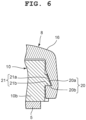
- the detachment prevention sections 18 include a plurality of first engaging projection sections 20 which are formed on the band attachment main bodies 10, and a plurality of first catching recess sections 21 which are formed in the inner surfaces of the cover sections 16 and with which the plurality of first engaging projection sections 20 is engaged, as shown in FIG. 2 , FIG. 5 and FIG. 6 .
- the plurality of first engaging projection sections 20 is formed on the sides of the outer surface of the pair of attachment arm sections 10b in each band attachment main body 10 of the case main body 6.
- the plurality of first engaging projection sections 20 provided on the sides of the outer surface of the pair of attachment arm sections 10b in each band attachment main body 10 is structured such that the corresponding fixing projection section 13 of the exterior member 7 is arranged therebetween, as shown in FIG. 2 , FIG. 5 and FIG. 6 .
- Each of these first engaging projection sections 20 is a projection whose cross-section has a substantially right triangle shape that gradually projects further from its upper side to its lower side, and has a first inclined surface 20a and a first lower surface 20b.
- the plurality of first catching recess sections 21 is inclined recess sections which have substantially rectangular shapes and with which the plurality of first engaging projection sections 20 is engaged, as shown in FIG. 2 , FIG. 5 and FIG. 6 .
- These first catching recess sections 21 are formed in sides of the inner surface of each cover section 16 of the fixing member 8 which corresponds to the sides of the outer surface of the pair of attachment arm sections 10b in each band attachment main body 10 of the case main body 6. More specifically, each first catching recess section 21 is formed to be an inclined recess section whose depth gradually becomes greater from its upper side to its lower side.
- each of these first catching recess sections 21 has an upper side inclined surface 21a and a lower side inner surface 21b.
- the detachment prevention sections 18 are structured such that, when the fixing member 8 is arranged covering the case main body 6, the plurality of first engaging projection sections 20 engages with the plurality of first catching recess sections 21, as shown in FIG. 2 , FIG. 5 and FIG. 6 . More specifically, these detachment prevention sections 18 are structured such that, when the cover sections 16 of the fixing member 8 are arranged covering the band attachment main bodies 10 of the case main body 6, the sides of the inner surfaces of the cover sections 16 are elastically deformed along the first inclined surfaces 20a of the first engaging projection sections 20 and the first engaging projection sections 20 engage with the plurality of first catching recess sections 21.
- these detachment prevention sections 18 are structured such that, when the cover sections 16 are elastically deformed and the first engaging projection sections 20 are inserted into and engaged with the first catching recess sections 21, the first engaging projection sections 20 are caught by the first catching recess sections 21 by the first inclined surfaces 20a of the first engaging projection sections 20 coming in pressure contact with the upper side inclined surfaces 21a in the first catching recess sections 21 and the first lower surfaces 20b of the first engaging projection sections 20 being pressed against the lower side inner surfaces 21b of the first catching recess sections 21, as shown in FIG. 2 , FIG. 5 and FIG. 6 . That is, the cover sections 16 of the fixing member 8 are structured to be attached to the band attachment main bodies 10 of the case main body 6 in a manner not to upwardly slip off the case main body 6.
- the press down restriction sections 19 include a plurality of second engaging projection sections 22 which is provided on outer peripheral portions of the case main body 6, and a plurality of second catching recess sections 23 which is provided in the inner surface of the fixing member 8 and with which the plurality of second engaging projection sections 22 is engaged, as shown in FIG. 2 , FIG. 7 and FIG. 8 .
- the press down restriction sections 19 are structured to restrict the fixing member 8 from being pressed down against the case main body 6 when the plurality of second engaging projection sections 22 engages with the plurality of second catching recess sections 23.
- the plurality of second engaging projection sections 22 is provided on portions on the three o' clock side and nine o'clock side of the outer peripheral surface of the case main body 6 which are positioned below the exterior main body 12 of the exterior main body 7, as shown in FIG. 2 , FIG. 7 and FIG. 8 .
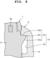
- Each of these second engaging projection sections 22 is an overhang projection whose cross-section has a substantially right triangle shape that gradually projects further from its lower side to its upper side, and has a second inclined surface 22a and a second upper surface 22b. Also, on an edge portion between the second inclined surface 22a and the second upper surface 22b, an arc-shaped chamfered section 22c is formed.
- the plurality of second catching recess sections 23 is substantially rectangular recess sections with which the plurality of second engaging projection sections 22 is engaged, as shown in FIG. 2 , FIG. 7 and FIG. 8 .
- These second catching recess sections 23 are provided in inner surface portions of the fixing main body section 15 of the fixing member 8 corresponding to the three o' clock side and nine o' clock side of the outer peripheral surface of the case main body 6.
- the plurality of second catching recess sections 23 is structured such that, when the fixing main body section 15 of the fixing member 8 is arranged covering the case main body 6, the plurality of second engaging projection sections 22 engages with these second catching recess sections 23.
- the press down restriction sections 19 are structured such that, when the fixing main body section 15 of the fixing member 8 is arranged covering the case main body 6, the inner surface of the fixing main body section 15 is elastically deformed to be stretched by the arc-shaped chamfered sections 22c provided on the edge portions between the second inclined surfaces 22a and the second upper surfaces 22b of the second engaging projection sections 22 and the second engaging projection sections 22 engage with the second catching recess sections 23, as shown in FIG. 2 , FIG. 7 and FIG. 8 .
- these press down restriction sections 19 are structured such that, when the fixing main body section 15 is elastically deformed and the second engaging projection sections 22 are inserted into and engaged with the second catching recess sections 23, the second engaging projection sections 22 are caught by the second catching recess sections 23 by the second upper surfaces 22b of the second engaging projection sections 22 being pressed against the upper inner surfaces of the second catching recess sections 23.
- these press down restriction sections 19 are structured to attach the fixing member 8 to the case main body 6 while defining the lower limit position of the fixing main body section 15 so that the fixing main body section 15 of the fixing member 8 does not downwardly slip off the case main body 6.
- this procedure first, the watch glass 4 is mounted in the upper opening of the case main body 6 together with the glass packing 4a, and the timepiece module (not shown) is mounted in the case main body 6.
- the back cover 5 is attached to the lower part of the case main body 6 together with the waterproof packing 5a, or the exterior member 7 is attached to the case main body 6 by the fixing member 8 and then the back cover 5 is attached to the lower part of the case main body 6 together with the waterproof packing 5a.
- the exterior member 7 is arranged on the case main body 6.
- the exterior main body 12 of the exterior member 7 is arranged on the upper portion of the case main body 6. More specifically, the upper surface section 12a of the exterior main body 12 is arranged covering the upper surface of the case main body 6, and the side surface section 12b is arranged covering the outer peripheral surface of the upper portion of the case main body 6 which corresponds to the portion mounted with the watch glass 4.
- the fixing projection sections 13 of the exterior member 7 are arranged on the placement sections 14 formed in the band attachment main bodies 10 of the case main body 6. More specifically, when the exterior main body 12 is arranged on the upper surface of the case main body 6 and the outer peripheral surface of the upper portion of the case main body 6 and the fixing projection sections 13 are arranged on the placement sections 14 of the band attachment main bodies 10 of the case main body 6, the inclined sections 13a of the fixing projection sections 13 are arranged on the inclined surface sections 14a of the placement sections 14 and the leg sections 13b of the fixing projection sections 13 are arranged on the recess sections 14b of the placement sections 14.
- the fixing member 8 is attached to the outer peripheral surface of the case main body 6 so as to fix the exterior member 7 to the case main body 6.
- the exterior main body 12 of the exterior member 7 arranged on the outer peripheral surface of the upper portion of the case main body 6 is inserted into the opening section 15a of the fixing main body section 15 of the fixing member 8, and protrudes above the fixing main body section 15 so as to be exposed.
- the fixing main body section 15 of the fixing member 8 is arranged covering the outer peripheral portion of the case main body 6 positioned below the exterior main body 12, and the pair of cover sections 16 is arranged covering the pair of band attachment main bodies 10 on the six o'clock side and the twelve o'clock side of the case main body 6.
- the plurality of attachment cylindrical sections 11 provided projecting outward on the two o'clock side, four o'clock side, eight o'clock side and ten o'clock side of the case main body 6 is inserted into the plurality of switch insertion holes 15b of the fixing main body section 15.
- the hold down sections 17 provided in the inner surfaces of the pair of cover sections 16 hold down the fixing projection sections 13 of the exterior member 7 on the placement sections 14 of the case main body 6 so as to fix the exterior member 7 to the case main body 6. More specifically, the inclined first hold down sections 17a of the hold down sections 17 of the cover sections 16 hold down the inclined sections 13a of the fixing projection sections 13 on the inclined surface sections 14a of the placement sections 14, and the second hold down sections 17b hold down the leg sections 13b of the fixing projection sections 13 on the recess sections 14b of the placement sections 14.
- the hold down sections 17 of the fixing member 8 hold down the fixing projection sections 13 of the exterior member 7 on the placement sections 14 of the case main body 6 with the exterior main body 12 of the exterior member 7 being arranged on the outer peripheral surface of the upper portion of the case main body 6 and exposed above the fixing main body section 15 of the fixing member 8. Accordingly, the exterior member 7 is fixed to the case main body 6.
- the fixing member 8 has been attached to the case main body 6 with its position with respect to the case main body 6 being restricted by the detachment prevention sections 18 and the press down restriction sections 19.
- the first inclined surfaces 20a of the first engaging projection sections 20 come in pressure contact with the upper side inclined surfaces 21a of the first catching recess sections 21, and the first lower surfaces 20b of the first engaging projection sections 20 are pressed against the lower side inner surfaces 21b of the first catching recess sections 21, whereby the first engaging projection sections 20 are locked.
- the cover sections 16 of the fixing member 8 are attached to the band attachment main bodies 10 of the case main body 6 in a manner not to upwardly slip off the case main body 6.
- the plurality of first engaging projection sections 20 has been formed on the pairs of attachment arm sections 10b at the sides of the band attachment main bodies 10 of the case main body 6 and each fixing projection section 13 of the exterior member 7 has been arranged between the corresponding first engaging projection sections 20. Accordingly, when the plurality of first engaging projection sections 20 is engaged with the plurality of first catching recess sections 21, the hold down sections 17 of the fixing member 8 reliably hold down the fixing projection sections 13 of the exterior member 7, and the cover sections 16 of the fixing member 8 are reliably attached to the band attachment main bodies 10 of the case main body 6.
- the inner surface of the fixing main body section 15 is elastically deformed to be stretched by the arc-shaped chamfered sections 22c formed on the edge portions between the second inclined surfaces 22a and the second upper surfaces 22b of the second engaging projection sections 22, and the second engaging projection sections 22 engage with the second catching recess sections 23.
- the second upper surfaces 22b of the second engaging projection sections 22 are pressed against the upper inner surfaces of the second catching recess sections 23, whereby the second engaging projection sections 22 are locked.
- the fixing member 8 has been attached to the case main body 6 with the press down restriction sections 19 defining the lower limit position of the fixing main body section 15 of the fixing member 8 such that the fixing main body section 15 does not downwardly slip off the case main body 6.
- the exterior member 7 is attached to the case main body 6 with the position of the fixing member 8 with respect to the case main body 6 being restricted by the detachment prevention sections 18 and the press down restriction sections 19 and the exterior main body 12 being arranged on the outer peripheral surface of the upper portion of the case main body 6 and exposed above the fixing main body section 15 of the fixing member 8.
- the hold down sections 17 of the fixing member 8 reliably holding down the fixing projection sections 13 on the placement sections 14 of the case main body 6, the exterior member 7 is reliably and favorably fixed to the case main body 6.
- the exterior member 7 can be easily detached and switched simply by the fixing member 8 being detached from the case main body 6. More specifically, when the fixing member 8 is to be detached from the case main body 6, the cover sections 16 of the fixing member 8 attached covering the band attachment main bodies 10 of the case main body 6 are shifted upward, whereby the restriction by the detachment prevention sections 18 is released.
- the hold down sections 17 of the fixing member 8 lift from the band attachment main bodies 10 of the case main body 6, whereby the hold down of the inclined sections 13a of the fixing projection sections 13 of the exterior member 7 by the first hold down sections 17a of the hold down sections 17 and the hold down of the leg sections 13b of the fixing projection sections 13 of the exterior member 7 by the second hold down sections 17a of the hold down sections 17 are released.
- the attachment cylindrical sections 11 of the plurality of switch sections 3 provided projecting outward on the two o'clock side, four o'clock side, eight o' clock side and ten o' clock side of the case main body 6 are separated from the plurality of switch insertion holes 15b formed in the fixing main body section 15 of the fixing member 8, and the restriction on the fixing member 8 by the press down restriction sections 19 is released.
- the fixing main body section 15 is detached from the exterior main body 12 of the exterior member 7 via the opening section 15a of the fixing main body section 15 of the fixing member 8.
- the fixing member 8 is detached from the case main body 6, whereby the exterior member 7 is detached from the case main body 6. Accordingly, the exterior member 7 can be easily switched.
- the exterior member 7 is switched as described above, the design and the appearance are changed by a new exterior member 7.
- the exterior member 7 is made of a decorative metal such as stainless steel and titanium alloy and the fixing member 8 is made of an elastic synthetic resin such as urethane, the decorative effect is improved by the differences in color, texture and the like between the exterior member 7 and the fixing member 8.
- the exterior member 7 of this wristwatch includes the exterior main body 12 which is arranged covering the outer surface of the case main body 6, and the fixing projection sections 13 which are formed on the predetermined lower edge portions of the exterior main body 12 while projecting toward the outer peripheral sides and held down on the case main body 6 by the fixing member 8 attached covering the outer peripheral surface of the case main body 6 excluding the exterior main body 12 so as to fix the exterior main body 12 to the case main body 6.
- the exterior member 7 can be easily switched.
- the exterior member 7 of this wristwatch has the simple structure where the fixing projection sections 13 formed on the predetermined lower edge portions of the exterior main body 12 are merely held down on the case main body 6 by the fixing member 8.
- the exterior main body 12 and the fixing projection sections 13 can be detached from the case main body 6 by the fixing member 8 being detached from the case main body 6, whereby the exterior member 7 can be easily switched.
- the wristwatch case 1 of this wristwatch includes the case main body 6, the exterior member 7 which has the exterior main body 12 arranged covering the outer surface of the case main body 6 and the fixing projection sections 13 formed on the predetermined lower edge portions of the exterior main body 12 while projecting toward the outer peripheral sides, and the fixing member 8 which is attached covering the outer peripheral surface of the case main body 6 with the exterior main body 12 of the exterior member 7 being exposed and holds down the fixing projection sections 13 on the case main body 6 so as to fix the exterior member 7 to the case main body 6.
- the exterior 7 can be easily switched.
- the wristwatch case 1 of this wristwatch has the simple structure where the fixing projection sections 13 formed on the predetermined lower edge portions of the exterior main body 12 are merely held down on the case main body 6 by the fixing member 8.
- the exterior main body 12 and the fixing projection sections 13 can be easily detached by the fixing member 8 being detached from the case main body 6, whereby the exterior member 7 can be easily switched.
- the exterior member 7 is made of metal
- the fixing member 8 is made of an elastic synthetic resin.
- this wristwatch case 1 has the two part structure where the exterior member 7 is made of metal and the fixing member 8 is made of an elastic synthetic resin, the design and the appearance can be improved by the differences in color, texture and the like between the exterior member 7 and the fixing member 8, whereby the wristwatch case 1 having a high decorative effect can be provided.
- the fixing member 8 includes the hold down sections 17 which hold down the fixing projection sections 13 on the case main body 6.
- the fixing projection sections 13 of the exterior member 7 can be arranged in the band attachment sections 2 on the six o' clock side and twelve o'clock side of the wristwatch case 1.
- the fixing projection sections 13 project toward the outer peripheral sides of the exterior main body 12, they do not become obstructive and can be reliably held down and fixed on the band attachment main bodies 10 of the band attachment sections 2 by the fixing member 8.
- the fixing projection sections 13 include the inclined sections 13a and the leg sections 13b
- the hold down sections 17 include the first hold down sections 17a and the second hold down sections 17b.
- the band attachment main bodies 10 are provided on the six o' clock side and twelve o'clock side of the case main body 6, and the placement sections 14 on which the fixing projection sections 13 are arranged are formed in the attachment projection sections 10a of the band attachment main bodies 10, whereby the fixing projection sections 13 of the exterior member 7 can be arranged on the placement sections 14 provided in the band attachment sections 2 of the wristwatch case 1.
- the hold down sections 17 of the fixing member 8 the fixing projection sections 13 can be reliably held down and fixed on the placement sections 14 of the attachment projection sections 10a of the band attachment main bodies 10.
- the placement sections 14 include the inclined surface sections 14a and the recess sections 14b, the inclined sections 13a of the fixing projection sections 13 can be arranged on the inclined surface sections 14a of the placement sections 14, and the leg sections 13b of the fixing projection sections 13 can be arranged in the recess sections 14b of the placement sections 14.
- the hold down sections 17 of the fixing member 8 the inclined sections 13a of the fixing projection sections 13 can be reliably held down on the inclined surface sections 14a of the placement sections 14, and the leg sections 13b of the fixing projection sections 13 can be reliably held down on the recess sections 14b of the placement sections 14.
- this wristwatch case 1 includes the detachment prevention sections 18 which restrict the fixing member 8 from upwardly slipping off the case main body 6, and the press down restriction sections 19 which restrict the fixing member 8 from being pressed down against the case main body 6.
- the vertical position of the fixing member 8 with respect to the case main body 6 can be reliably and favorably restricted by the detachment prevention sections 18 and the press down restriction sections 19, whereby the fixing member 8 can be reliably attached to the case main body 6.
- the detachment prevention sections 18 include the plurality of first engaging projection sections 20 which is provided on outer peripheral portions of the case main body 6, and the plurality of first catching recess sections 21 which is provided in the inner surface of the fixing member 8 and with which the plurality of first engaging projection sections 20 is engaged.
- the fixing member 8 can be reliably restricted from upwardly slipping off the case main body 6 and reliably attached to the case main body 6.
- the first engaging projection sections 20 are projections whose cross-sections have substantially right triangle shapes that gradually project further from their upper sides to their lower sides and which have the first inclined surfaces 20a and the first lower surfaces 20b, and the first catching recess sections 21 are inclined recess sections whose depths gradually become greater from their upper sides to their lower side.
- the fixing member 8 when the fixing member 8 is elastically deformed to be gradually stretched and the first engaging projection sections 20 is inserted into and engaged with the first catching recess sections 21, the first inclined surfaces 20a of the first engaging projection sections 20 come in pressure contact with the upper side inclined surfaces 21a of the first catching recess sections 21 and the first lower surfaces 20b of the first engaging projection sections 20 are reliably and favorably pressed against the lower side inner surfaces 21b of the first catching recess sections 21, whereby the first engaging projection sections 20 can be caught by the first catching recess sections 21 .
- the fixing member 8 can be attached to the case main body 6 in a manner not to upwardly slip off the case main body 6.
- the plurality of first engaging projection sections 20 is provided on the pairs of attachment arm sections 10b at the sides of the band attachment main bodies 10 of the case main body 6, and the fixing projection sections 13 of the exterior member 7 are arranged between the corresponding first engaging projection sections 20.
- the plurality of first engaging projection sections 20 can be engaged with the plurality of first catching recess sections 21 and the cover sections 16 of the fixing member 8 can be held down on and attached to the band attachment main bodies 10 of the case main body 6, whereby the fixing projection sections 13 of the exterior member 7 arranged between the plurality of first engaging projection sections 20 can be reliably held down by the hold down member 17 of the fixing member 8.
- the press down restriction sections 19 include the plurality of second engaging projection sections 22 which is formed on the outer peripheral portions of the case main body 6, and the plurality of second catching recess sections 23 which is provided in the inner surface of the fixing member 8 and with which the plurality of second engaging projection sections 22 is engaged.
- the fixing member 8 can be reliably restricted from being pressed down against the case main body 6 and reliably attached to the case main body 6.
- the second engaging projection sections 22 are overhang projections whose cross-sections have substantially right triangle shapes that gradually project further from their lower sides to their upper sides and which have the second inclined surfaces 22a, the second upper surfaces 22b and the arc-shaped chamfered sections 22c, and the second catching recess sections 23 are substantially rectangular recess sections.
- the fixing member 8 can be favorably attached to the case main body 6 with the lower limit position of the fixing main body section 15 being defined so that the fixing main body section 15 of the fixing member 8 does not downwardly slip off the case main body 6.
- the fixing projection sections 13 are provided on the six o'clock side and twelve o'clock side of the exterior member 7.
- the present invention is not limited thereto, and the fixing projection sections 13 may be provided on any portion of the lower edges of the exterior member 7.
- the number of the fixing projection sections 13 is not necessarily required to be two, and three or more of them may be provided.
- the detachment prevention sections 18 are provided on the six o'clock side and twelve o'clock side of the case main body 6 and those of the fixing member 8.
- the present invention is not limited thereto, and the detachment prevention sections 18 may be provided at any portion of the case main body 6 and the fixing member 8.
- the detachment prevention sections 18 are not necessarily required to be provided in two portions and may be provided in three or more portions.
- the detachment prevention sections 18 include the first engaging projection sections 20 formed on the case main body 6 and the first catching recess sections 21 formed in the fixing member 8.
- the present invention is not limited thereto, and a structure may be adopted in which the detachment prevention sections 18 include first catching recess sections formed in the case main body 6 and first engaging projection sections formed on the fixing member 8.
- the press down restriction sections 19 are provided on the three o' clock side and nine o' clock side of the case main body 6 and those of the fixing member 8.
- the present invention is not limited thereto, and the press down restriction sections 19 may be provided at any portion of the case main body 6 and the fixing member 8.
- the press down restriction sections 19 are not necessarily required to be provided in two portions and may be provided in three or more portions.
- the press down restriction sections 19 include the second engaging projection sections 22 formed on the case main body 6 and the second catching recess sections 23 formed in the fixing member 8.
- the present invention is not limited thereto, and a structure may be adopted in which the press down restriction sections 19 include second catching recess sections formed in the case main body 6 and second engaging projection sections formed on the fixing member 8.
- the present invention is applicable to various types of timepieces such as a travel watch, an alarm clock, a table clock, and a wall clock, and electronic devices such as a cellular phone and a portable information terminal.
Landscapes
- Physics & Mathematics (AREA)
- General Physics & Mathematics (AREA)
- Engineering & Computer Science (AREA)
- Manufacturing & Machinery (AREA)
- Electric Clocks (AREA)
Abstract
Description
- The present invention relates to an exterior member that is used for electronic devices such as wristwatches, a case equipped with the exterior member, and a timepiece equipped with the exterior member and the case.
- For example, a wristwatch is known which has a structure where an exterior member is interchangeably attached to a case, as described in
Patent Document 1. In the case of this wristwatch, the exterior member includes a decorative section with decoration and fitting sections provided on peripheral edges of the decorative section so as to be arranged on the peripheral surface of the case. - Patent Document 1:
JP H11-44775 U - However, this type of wristwatch has a problem in that, due to the structure where the exterior member is attached to the case by the decorative section of the exterior member being arranged on the upper surface of the case and the fitting sections of the exterior member being fitted together with the peripheral surface of the case, the exterior member tends to come off the case when the fitting of the case and the exterior member is loose, or the case may be damaged when the fitting of the case and the exterior member is tight.
- In order to solve this problem, an exterior member has been conceived which has a structure where a decorative section is provided with engaging sections into which watch bands are inserted and which engage with band attachment sections of a case. However, this exterior member has a problem in that, due to the structure where the watch bands are required to be inserted into the engaging sections of the exterior member, the attachment and detachment of the exterior member is bothersome and therefore the exterior member cannot be easily switched.
- An object of the present invention is to provide an easily interchangeable exterior member, a case equipped with the exterior member, and a timepiece equipped with the exterior member and the case.
- An embodiment of the present invention is an exterior member characterized by comprising: an exterior main body which covers an outer surface of a case main body; and fixing projection sections which are formed on predetermined lower edge portions of the exterior main body while projecting toward outer peripheral sides and fix the exterior main body to the case main body by a fixing member attached covering an outer peripheral surface of the case main body.
- Another embodiment of the present invention is a case characterized by comprising: a case main body; an exterior member which has an exterior main body covering an outer surface of the case main body and fixing projection sections formed on predetermined lower edge portions of the exterior main body while projecting toward outer peripheral sides; and a fixing member which is attached covering an outer peripheral surface of the case main body and fixes the exterior member to the case main body by holding down the fixing projection sections on the case main body.
- According to the present invention, an easily interchangeable exterior member can be provided.
-
-
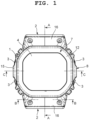
FIG. 1 is an enlarged front view of an embodiment where the present invention has been applied in a wristwatch; -
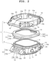
FIG. 2 is an exploded and enlarged perspective view of a wristwatch case shown inFIG. 1 ; -
FIG. 3 is an enlarged cross-sectional view of the wristwatch case taken along the A-A arrow view inFIG. 1 ; -
FIG. 4 is an enlarged cross-sectional view of the A portion of the wristwatch case shown inFIG. 3 ; -
FIG. 5 is an enlarged cross-sectional view of the wristwatch case taken along the B-B arrow view inFIG. 1 ; -
FIG. 6 is an enlarged cross-sectional view of the B portion of the wristwatch case shown inFIG. 5 ; -
FIG. 7 is an enlarged cross-sectional view of the wristwatch case taken along the C-C arrow view inFIG. 1 ; and -
FIG. 8 is an enlarged cross-sectional view of the C portion of the wristwatch case shown inFIG. 7 . - An embodiment where the present invention has been applied in a wristwatch will hereinafter be described with reference to
FIG. 1 to FIG. 8 . - This wristwatch includes a
wristwatch case 1, as shown inFIG. 1 to FIG. 3 . On the twelve o'clock side and six o'clock side of thiswristwatch case 1, later-describedband attachment sections 2 to which watch bands (not shown) are attached are provided. - On the two o'clock side, four o'clock side, eight o'clock side and ten o'clock side of this
wristwatch case 1,switch sections 3 are provided, as shown inFIG. 1 . Also, to the upper opening of thiswristwatch case 1, awatch glass 4 is attached via aglass packing 4a, as shown inFIG. 1 to FIG. 3 . To the lower part of thiswristwatch case 1, aback cover 5 is attached by a plurality ofscrews 5b (refer toFIG. 5 ) via awaterproof packing 5a. In thiswristwatch case 1, a timepiece module (not shown) is provided. - This
wristwatch case 1 includes a casemain body 6, anexterior member 7 and afixing member 8, as shown inFIG. 1 to FIG. 3 . The casemain body 6 is made of a light-weight and high-strength synthetic resin acquired by carbon fiber or glass fiber being mixed into a highly rigid polyamide resin. In a peripheral portion of this casemain body 6, ametal reinforcement member 6a is embedded, a portion of which protrudes toward the inner side of the casemain body 6. Note that the material of this casemain body 6 is not limited to synthetic resin and may be metal. - On the twelve o'clock side and six o'clock side of this case
main body 6, band attachmentmain bodies 10 of theband attachment sections 2 are provided projecting outward, as shown inFIG. 2 andFIG. 3 . Each band attachmentmain body 10 includes anattachment projection section 10a provided projecting outward from the outer peripheral surface of the case main body, and a pair ofattachment arm sections 10b provided on side portions of theattachment projection section 10a. - This band attachment
main body 10 is structured such that an end portion of the corresponding watch band (not shown) is arranged and attached between the pair ofattachment arm sections 10b, and theattachment projection section 10a and the pair ofattachment arm sections 10b are covered by a later-describedcover section 16 of thefixing member 8, as shown inFIG. 2 andFIG. 3 . Also, on the two o'clock side, four o'clock side, eight o'clock side and ten o'clock side of thiswristwatch case 1, a plurality of attachmentcylindrical sections 11 into which operation buttons (not shown) of the plurality ofswitch sections 3 are inserted to be attached is provided projecting toward the outside of the casemain body 6, as shown inFIG. 1 andFIG. 2 . - The
exterior member 7 includes an exteriormain body 12 which is arranged covering the outer surface of the casemain body 6, andfixing projection sections 13 formed on predetermined lower edge portions of the exteriormain body 12 while projecting toward outer peripheral sides, as shown inFIG. 1 to FIG. 3 . Thisexterior member 7 is a decorative member and made of a highly rigid metal such as stainless steel and titanium alloy. - The exterior
main body 12 is formed to be arranged covering the upper surface of the casemain body 6 and the outer peripheral surface of an upper portion of the casemain body 6 which corresponds to a portion where thewatch glass 4 is attached, as shown inFIG. 1 to FIG. 3 . More specifically, this exteriormain body 12 includes anupper surface section 12a which is arranged on the upper surface of the casemain body 6, and aside surface section 12b which is arranged on the outer peripheral portion of the upper side of the casemain body 6 or, in other words, the outer peripheral surface of the upper portion of the casemain body 6 which corresponds to the portion where thewatch glass 4 is attached. - In an area between the
upper surface section 12a of the exteriormain body 12 and the upper surface of the casemain body 6, abuffering sheet 12c is arranged, as shown inFIG. 4 . Thisbuffering sheet 12c, which buffers an external impact exerted on theexterior member 7 such that the impact is not transmitted to the casemain body 6, is attached to the upper surface of the casemain body 6 and the upper surface of theglass packing 4a of thewatch glass 4 with a double coatedadhesive tape 12d. - The
fixing projection sections 13 are formed projecting outward from the lower edge portions of the exteriormain body 12 on the six o'clock side and the twelve o'clock side along the band attachmentmain bodies 10 of the casemain body 6 in theband attachment sections 2 of thewristwatch case 1, as shown inFIG. 2 to FIG. 4 . More specifically, eachfixing projection section 13 includes aninclined section 13a inclined diagonally downward from the corresponding lower edge portion of the exteriormain body 12 toward the outside of the casemain body 6, and aleg section 13b provided in a flat plate shape on the lower end of thisinclined section 13a. Thisleg section 13b is formed such that its thickness is equal to or greater than that of the exteriormain body 12 so as to have sufficient strength. - Also, the
fixing projection sections 13 are structured such that, when the exteriormain body 12 is arranged on the upper surface of the casemain body 6 and the outer peripheral surface of the upper portion of the casemain body 6, thesefixing projection sections 13 are arranged onplacement sections 14 formed in the band attachmentmain bodies 10 of the casemain body 6, as shown inFIG. 2 to FIG. 4 . More specifically, eachplacement section 14 includes aninclined surface section 14a on which theinclined section 13a of the correspondingfixing projection section 13 is arranged, and arecess section 14b on which theleg section 13b is arranged. Theinclined surface section 14a is formed to have the same inclination as theinclined section 13a of thefixing projection section 13, and therecess section 14b is formed to have the same shape and size as theleg section 13b. - The
fixing member 8, which also serves as a decorative second exterior member, is made of an elastic synthetic resin such as urethane resin, as shown inFIG. 1 to FIG. 3 . Thisfixing member 8 is structured to be attached to the outer peripheral surface of the casemain body 6 and fix theexterior member 7 to the casemain body 6 with the exteriormain body 12 of theexterior member 7 being exposed. - More specifically, this
fixing member 8 includes a fixingmain body section 15 which is arranged covering the outer peripheral surface of the casemain body 6, and a pair ofcover sections 16 which is arranged covering the band attachmentmain bodies 10 on the six o'clock side and twelve o'clock side of the casemain body 6, as shown inFIG. 1 to FIG. 3 . The fixingmain body section 15 is formed to be arranged covering the outer peripheral surface of the casemain body 6 excluding a portion where the exteriormain body 12 of theexterior member 7 is arranged. - More specifically, in this fixing
main body section 15, anopening section 15a into which the exteriormain body 12 of the exteriormain body 7 is inserted to protrude upward is formed in the same shape as the outer shape of the exteriormain body 12, as shown inFIG. 2 . Also, in this fixingmain body section 15, a plurality ofswitch insertion holes 15b is formed into which the attachmentcylindrical sections 11 of the plurality ofswitch sections 3 provided on the two o'clock side, four o'clock side, eight o'clock side and ten o'clock side of the casemain body 6 are inserted and arranged. Theseswitch insertion holes 15b, into which the operation buttons (not shown) of the plurality ofswitch sections 3 are inserted, are formed such that each inner diameter is greater than the outer diameter of each attachmentcylindrical section 11. - On the other hand, the pair of
cover sections 16 is structured to be arranged covering the band attachmentmain bodies 10 provided on the six o'clock side and twelve o'clock side of the casemain body 6, as shown inFIG. 1 to FIG. 3 . More specifically, each of thesecover sections 16 is arranged covering the upper surface and side surfaces of the corresponding band attachmentmain body 10 of the casemain body 6, which are sides of the outer surface of the pair ofattachment arm sections 10b of the band attachmentmain body 10. That is, eachband attachment section 2 of thewristwatch case 1 includes the corresponding band attachmentmain body 10 of the casemain body 6 and thecorresponding cover section 16 of thefixing member 8. - In the inner surfaces of these
cover sections 16, hold downsections 17 are provided which hold down thefixing projection sections 13 of theexterior member 7 on theplacement sections 14 formed in theattachment projection sections 10a of the band attachmentmain bodies 10 of the casemain body 6, as shown inFIG. 2 to FIG. 4 . Each hold downsection 17 includes an inclined first hold downsection 17a which holds down theinclined section 13a of the fixingprojection section 13 on theinclined surface section 14a of thecorresponding placement section 14, and a second hold downsection 17b which holds down theleg section 13b on therecess section 14b of theplacement section 14. - As a result, the fixing
member 8 is structured such that, when the fixingmain body section 15 is arranged on the outer peripheral surface of the casemain body 6 and thecover sections 16 are arranged on the band attachmentmain bodies 10 of the casemain body 6 with the exteriormain body 12 of theexterior member 7 on the upper surface and outer peripheral surface of the upper portion of the casemain body 6 protruding upward from theopening section 15a of the fixingmain body section 15 and being exposed, the hold downsections 17 of thecover sections 16 hold down the fixingprojection sections 13 of theexterior member 7 on theplacement sections 14 of theattachment projection sections 10a of the casemain body 6 so as to fix theexterior member 7 to the casemain body 6, as shown inFIG. 3 . - More specifically, this fixing
member 8 is structured such that, when thecover sections 16 are arranged on the band attachmentmain bodies 10, the first hold downsections 17a of the hold downsections 17 of thecover sections 16 hold down theinclined sections 13a of the fixingprojection sections 13 of theexterior member 7 on theinclined surface sections 14a of theplacement sections 14 formed in theattachment projection sections 10a of the casemain body 6 and the second hold downsections 17b of the hold downsections 17 hold down theleg sections 13b of the fixingprojection sections 13 on therecess sections 14b of theplacement sections 14 of the casemain body 6 so as to fix theexterior member 7 to the casemain body 6, as shown inFIG. 3 . - Also, this fixing
member 8 includesdetachment prevention sections 18 which restrict the fixingmember 8 from upwardly slipping off the casemain body 6, and press downrestriction sections 19 which restrict the fixingmember 8 from being pressed down against the casemain body 6, as shown inFIG. 5 to FIG. 8 . As a result, the fixingmember 8 is structured to be attached to thecase member 6 with its vertical position with respect to the casemain body 6 being restricted by thedetachment prevention sections 18 and the press downrestriction sections 19. - The
detachment prevention sections 18 include a plurality of first engagingprojection sections 20 which are formed on the band attachmentmain bodies 10, and a plurality of first catchingrecess sections 21 which are formed in the inner surfaces of thecover sections 16 and with which the plurality of first engagingprojection sections 20 is engaged, as shown inFIG. 2 ,FIG. 5 andFIG. 6 . The plurality of first engagingprojection sections 20 is formed on the sides of the outer surface of the pair ofattachment arm sections 10b in each band attachmentmain body 10 of the casemain body 6. - The plurality of first engaging
projection sections 20 provided on the sides of the outer surface of the pair ofattachment arm sections 10b in each band attachmentmain body 10 is structured such that the corresponding fixingprojection section 13 of theexterior member 7 is arranged therebetween, as shown inFIG. 2 ,FIG. 5 andFIG. 6 . Each of these firstengaging projection sections 20 is a projection whose cross-section has a substantially right triangle shape that gradually projects further from its upper side to its lower side, and has a firstinclined surface 20a and a firstlower surface 20b. - The plurality of first catching
recess sections 21 is inclined recess sections which have substantially rectangular shapes and with which the plurality of first engagingprojection sections 20 is engaged, as shown inFIG. 2 ,FIG. 5 andFIG. 6 . These first catchingrecess sections 21 are formed in sides of the inner surface of eachcover section 16 of the fixingmember 8 which corresponds to the sides of the outer surface of the pair ofattachment arm sections 10b in each band attachmentmain body 10 of the casemain body 6. More specifically, each first catchingrecess section 21 is formed to be an inclined recess section whose depth gradually becomes greater from its upper side to its lower side. Here, each of these first catchingrecess sections 21 has an upper side inclinedsurface 21a and a lower sideinner surface 21b. - As a result, the
detachment prevention sections 18 are structured such that, when the fixingmember 8 is arranged covering the casemain body 6, the plurality of first engagingprojection sections 20 engages with the plurality of first catchingrecess sections 21, as shown inFIG. 2 ,FIG. 5 andFIG. 6 . More specifically, thesedetachment prevention sections 18 are structured such that, when thecover sections 16 of the fixingmember 8 are arranged covering the band attachmentmain bodies 10 of the casemain body 6, the sides of the inner surfaces of thecover sections 16 are elastically deformed along the firstinclined surfaces 20a of the firstengaging projection sections 20 and the firstengaging projection sections 20 engage with the plurality of first catchingrecess sections 21. - Also, these
detachment prevention sections 18 are structured such that, when thecover sections 16 are elastically deformed and the firstengaging projection sections 20 are inserted into and engaged with the firstcatching recess sections 21, the firstengaging projection sections 20 are caught by the firstcatching recess sections 21 by the firstinclined surfaces 20a of the firstengaging projection sections 20 coming in pressure contact with the upper side inclinedsurfaces 21a in the firstcatching recess sections 21 and the firstlower surfaces 20b of the firstengaging projection sections 20 being pressed against the lower sideinner surfaces 21b of the firstcatching recess sections 21, as shown inFIG. 2 ,FIG. 5 andFIG. 6 . That is, thecover sections 16 of the fixingmember 8 are structured to be attached to the band attachmentmain bodies 10 of the casemain body 6 in a manner not to upwardly slip off the casemain body 6. - On the other hand, the press down
restriction sections 19 include a plurality of secondengaging projection sections 22 which is provided on outer peripheral portions of the casemain body 6, and a plurality of second catchingrecess sections 23 which is provided in the inner surface of the fixingmember 8 and with which the plurality of secondengaging projection sections 22 is engaged, as shown inFIG. 2 ,FIG. 7 andFIG. 8 . As a result, the press downrestriction sections 19 are structured to restrict the fixingmember 8 from being pressed down against the casemain body 6 when the plurality of secondengaging projection sections 22 engages with the plurality of second catchingrecess sections 23. - The plurality of second
engaging projection sections 22 is provided on portions on the three o' clock side and nine o'clock side of the outer peripheral surface of the casemain body 6 which are positioned below the exteriormain body 12 of the exteriormain body 7, as shown inFIG. 2 ,FIG. 7 andFIG. 8 . Each of these secondengaging projection sections 22 is an overhang projection whose cross-section has a substantially right triangle shape that gradually projects further from its lower side to its upper side, and has a secondinclined surface 22a and a secondupper surface 22b. Also, on an edge portion between the secondinclined surface 22a and the secondupper surface 22b, an arc-shapedchamfered section 22c is formed. - The plurality of second catching
recess sections 23 is substantially rectangular recess sections with which the plurality of secondengaging projection sections 22 is engaged, as shown inFIG. 2 ,FIG. 7 andFIG. 8 . These secondcatching recess sections 23 are provided in inner surface portions of the fixingmain body section 15 of the fixingmember 8 corresponding to the three o' clock side and nine o' clock side of the outer peripheral surface of the casemain body 6. As a result, the plurality of second catchingrecess sections 23 is structured such that, when the fixingmain body section 15 of the fixingmember 8 is arranged covering the casemain body 6, the plurality of secondengaging projection sections 22 engages with these secondcatching recess sections 23. - That is, the press down
restriction sections 19 are structured such that, when the fixingmain body section 15 of the fixingmember 8 is arranged covering the casemain body 6, the inner surface of the fixingmain body section 15 is elastically deformed to be stretched by the arc-shapedchamfered sections 22c provided on the edge portions between the secondinclined surfaces 22a and the secondupper surfaces 22b of the secondengaging projection sections 22 and the secondengaging projection sections 22 engage with the secondcatching recess sections 23, as shown inFIG. 2 ,FIG. 7 andFIG. 8 . - Also, these press down
restriction sections 19 are structured such that, when the fixingmain body section 15 is elastically deformed and the secondengaging projection sections 22 are inserted into and engaged with the secondcatching recess sections 23, the secondengaging projection sections 22 are caught by the secondcatching recess sections 23 by the secondupper surfaces 22b of the secondengaging projection sections 22 being pressed against the upper inner surfaces of the secondcatching recess sections 23. As a result, these press downrestriction sections 19 are structured to attach the fixingmember 8 to the casemain body 6 while defining the lower limit position of the fixingmain body section 15 so that the fixingmain body section 15 of the fixingmember 8 does not downwardly slip off the casemain body 6. - Next, a procedure for assembling this
wristwatch case 1 is described. In this procedure, first, thewatch glass 4 is mounted in the upper opening of the casemain body 6 together with theglass packing 4a, and the timepiece module (not shown) is mounted in the casemain body 6. In this state, theback cover 5 is attached to the lower part of the casemain body 6 together with thewaterproof packing 5a, or theexterior member 7 is attached to the casemain body 6 by the fixingmember 8 and then theback cover 5 is attached to the lower part of the casemain body 6 together with thewaterproof packing 5a. - Subsequently, the
exterior member 7 is arranged on the casemain body 6. Here, the exteriormain body 12 of theexterior member 7 is arranged on the upper portion of the casemain body 6. More specifically, theupper surface section 12a of the exteriormain body 12 is arranged covering the upper surface of the casemain body 6, and theside surface section 12b is arranged covering the outer peripheral surface of the upper portion of the casemain body 6 which corresponds to the portion mounted with thewatch glass 4. - Also, here, the fixing
projection sections 13 of theexterior member 7 are arranged on theplacement sections 14 formed in the band attachmentmain bodies 10 of the casemain body 6. More specifically, when the exteriormain body 12 is arranged on the upper surface of the casemain body 6 and the outer peripheral surface of the upper portion of the casemain body 6 and the fixingprojection sections 13 are arranged on theplacement sections 14 of the band attachmentmain bodies 10 of the casemain body 6, theinclined sections 13a of the fixingprojection sections 13 are arranged on theinclined surface sections 14a of theplacement sections 14 and theleg sections 13b of the fixingprojection sections 13 are arranged on therecess sections 14b of theplacement sections 14. - In this state, the fixing
member 8 is attached to the outer peripheral surface of the casemain body 6 so as to fix theexterior member 7 to the casemain body 6. Here, the exteriormain body 12 of theexterior member 7 arranged on the outer peripheral surface of the upper portion of the casemain body 6 is inserted into theopening section 15a of the fixingmain body section 15 of the fixingmember 8, and protrudes above the fixingmain body section 15 so as to be exposed. - Accordingly, the fixing
main body section 15 of the fixingmember 8 is arranged covering the outer peripheral portion of the casemain body 6 positioned below the exteriormain body 12, and the pair ofcover sections 16 is arranged covering the pair of band attachmentmain bodies 10 on the six o'clock side and the twelve o'clock side of the casemain body 6. Here, the plurality of attachmentcylindrical sections 11 provided projecting outward on the two o'clock side, four o'clock side, eight o'clock side and ten o'clock side of the casemain body 6 is inserted into the plurality of switch insertion holes 15b of the fixingmain body section 15. - Also, here, the hold down
sections 17 provided in the inner surfaces of the pair ofcover sections 16 hold down the fixingprojection sections 13 of theexterior member 7 on theplacement sections 14 of the casemain body 6 so as to fix theexterior member 7 to the casemain body 6. More specifically, the inclined first hold downsections 17a of the hold downsections 17 of thecover sections 16 hold down theinclined sections 13a of the fixingprojection sections 13 on theinclined surface sections 14a of theplacement sections 14, and the second hold downsections 17b hold down theleg sections 13b of the fixingprojection sections 13 on therecess sections 14b of theplacement sections 14. - As a result, the hold down
sections 17 of the fixingmember 8 hold down the fixingprojection sections 13 of theexterior member 7 on theplacement sections 14 of the casemain body 6 with the exteriormain body 12 of theexterior member 7 being arranged on the outer peripheral surface of the upper portion of the casemain body 6 and exposed above the fixingmain body section 15 of the fixingmember 8. Accordingly, theexterior member 7 is fixed to the casemain body 6. In this state, the fixingmember 8 has been attached to the casemain body 6 with its position with respect to the casemain body 6 being restricted by thedetachment prevention sections 18 and the press downrestriction sections 19. - In the case of these
detachment prevention sections 18, when thecover sections 16 of the fixingmember 8 are arranged covering the band attachmentmain bodies 10 of the casemain body 6, the sides of the inner surfaces of thecover sections 16 are elastically deformed to be gradually stretched along the firstinclined surfaces 20a of the firstengaging projection sections 20 and the firstengaging projection sections 20 engage with the firstcatching recess sections 21. - Then, in the
detachment prevention sections 18, the firstinclined surfaces 20a of the firstengaging projection sections 20 come in pressure contact with the upper side inclinedsurfaces 21a of the firstcatching recess sections 21, and the firstlower surfaces 20b of the firstengaging projection sections 20 are pressed against the lower sideinner surfaces 21b of the firstcatching recess sections 21, whereby the firstengaging projection sections 20 are locked. As a result, thecover sections 16 of the fixingmember 8 are attached to the band attachmentmain bodies 10 of the casemain body 6 in a manner not to upwardly slip off the casemain body 6. - Here, the plurality of first engaging
projection sections 20 has been formed on the pairs ofattachment arm sections 10b at the sides of the band attachmentmain bodies 10 of the casemain body 6 and each fixingprojection section 13 of theexterior member 7 has been arranged between the corresponding first engagingprojection sections 20. Accordingly, when the plurality of first engagingprojection sections 20 is engaged with the plurality of first catchingrecess sections 21, the hold downsections 17 of the fixingmember 8 reliably hold down the fixingprojection sections 13 of theexterior member 7, and thecover sections 16 of the fixingmember 8 are reliably attached to the band attachmentmain bodies 10 of the casemain body 6. - With regard to the press down
restriction sections 19, when the fixingmain body section 15 of the fixingmember 8 is arranged covering the casemain body 6, the inner surface of the fixingmain body section 15 is elastically deformed to be stretched by the arc-shapedchamfered sections 22c formed on the edge portions between the secondinclined surfaces 22a and the secondupper surfaces 22b of the secondengaging projection sections 22, and the secondengaging projection sections 22 engage with the secondcatching recess sections 23. - Here, in the press down
restriction sections 19, the secondupper surfaces 22b of the secondengaging projection sections 22 are pressed against the upper inner surfaces of the secondcatching recess sections 23, whereby the secondengaging projection sections 22 are locked. In this state, the fixingmember 8 has been attached to the casemain body 6 with the press downrestriction sections 19 defining the lower limit position of the fixingmain body section 15 of the fixingmember 8 such that the fixingmain body section 15 does not downwardly slip off the casemain body 6. - As a result, the
exterior member 7 is attached to the casemain body 6 with the position of the fixingmember 8 with respect to the casemain body 6 being restricted by thedetachment prevention sections 18 and the press downrestriction sections 19 and the exteriormain body 12 being arranged on the outer peripheral surface of the upper portion of the casemain body 6 and exposed above the fixingmain body section 15 of the fixingmember 8. Here, by the hold downsections 17 of the fixingmember 8 reliably holding down the fixingprojection sections 13 on theplacement sections 14 of the casemain body 6, theexterior member 7 is reliably and favorably fixed to the casemain body 6. - Next, a procedure for switching the
exterior member 7 of thiswristwatch case 1 is described. In this embodiment, theexterior member 7 can be easily detached and switched simply by the fixingmember 8 being detached from the casemain body 6. More specifically, when the fixingmember 8 is to be detached from the casemain body 6, thecover sections 16 of the fixingmember 8 attached covering the band attachmentmain bodies 10 of the casemain body 6 are shifted upward, whereby the restriction by thedetachment prevention sections 18 is released. - Here, when the
cover sections 16 of the fixingmember 8 are elastically deformed to be warped and shifted upward, the firstcatching recess sections 21 formed in side portions of thecover sections 16 are disengaged from the firstengaging projection sections 20 provided on the pairs ofattachment arm sections 10b of the band attachmentmain bodies 10. As a result, the restriction on the fixingmember 8 by thedetachment prevention sections 18 is released, whereby the hold down of the fixingprojection sections 13 of theexterior member 7 by the hold downsections 17 of the fixingmember 8 is released. - More specifically, when the restriction on the fixing
member 8 by thedetachment prevention sections 18 is released, the hold downsections 17 of the fixingmember 8 lift from the band attachmentmain bodies 10 of the casemain body 6, whereby the hold down of theinclined sections 13a of the fixingprojection sections 13 of theexterior member 7 by the first hold downsections 17a of the hold downsections 17 and the hold down of theleg sections 13b of the fixingprojection sections 13 of theexterior member 7 by the second hold downsections 17a of the hold downsections 17 are released. - Also, here, the attachment
cylindrical sections 11 of the plurality ofswitch sections 3 provided projecting outward on the two o'clock side, four o'clock side, eight o' clock side and ten o' clock side of the casemain body 6 are separated from the plurality ofswitch insertion holes 15b formed in the fixingmain body section 15 of the fixingmember 8, and the restriction on the fixingmember 8 by the press downrestriction sections 19 is released. - In this state, the fixing
main body section 15 is detached from the exteriormain body 12 of theexterior member 7 via theopening section 15a of the fixingmain body section 15 of the fixingmember 8. As a result, the fixingmember 8 is detached from the casemain body 6, whereby theexterior member 7 is detached from the casemain body 6. Accordingly, theexterior member 7 can be easily switched. - When the
exterior member 7 is switched as described above, the design and the appearance are changed by anew exterior member 7. In this embodiment, since theexterior member 7 is made of a decorative metal such as stainless steel and titanium alloy and the fixingmember 8 is made of an elastic synthetic resin such as urethane, the decorative effect is improved by the differences in color, texture and the like between theexterior member 7 and the fixingmember 8. - As described above, the
exterior member 7 of this wristwatch includes the exteriormain body 12 which is arranged covering the outer surface of the casemain body 6, and the fixingprojection sections 13 which are formed on the predetermined lower edge portions of the exteriormain body 12 while projecting toward the outer peripheral sides and held down on the casemain body 6 by the fixingmember 8 attached covering the outer peripheral surface of the casemain body 6 excluding the exteriormain body 12 so as to fix the exteriormain body 12 to the casemain body 6. As a result, theexterior member 7 can be easily switched. - That is, the
exterior member 7 of this wristwatch has the simple structure where the fixingprojection sections 13 formed on the predetermined lower edge portions of the exteriormain body 12 are merely held down on the casemain body 6 by the fixingmember 8. As a result, the exteriormain body 12 and the fixingprojection sections 13 can be detached from the casemain body 6 by the fixingmember 8 being detached from the casemain body 6, whereby theexterior member 7 can be easily switched. - Also, the
wristwatch case 1 of this wristwatch includes the casemain body 6, theexterior member 7 which has the exteriormain body 12 arranged covering the outer surface of the casemain body 6 and the fixingprojection sections 13 formed on the predetermined lower edge portions of the exteriormain body 12 while projecting toward the outer peripheral sides, and the fixingmember 8 which is attached covering the outer peripheral surface of the casemain body 6 with the exteriormain body 12 of theexterior member 7 being exposed and holds down the fixingprojection sections 13 on the casemain body 6 so as to fix theexterior member 7 to the casemain body 6. As a result, theexterior 7 can be easily switched. - That is, the
wristwatch case 1 of this wristwatch has the simple structure where the fixingprojection sections 13 formed on the predetermined lower edge portions of the exteriormain body 12 are merely held down on the casemain body 6 by the fixingmember 8. As a result, the exteriormain body 12 and the fixingprojection sections 13 can be easily detached by the fixingmember 8 being detached from the casemain body 6, whereby theexterior member 7 can be easily switched. - Also, in the case of this
wristwatch case 1, theexterior member 7 is made of metal, and the fixingmember 8 is made of an elastic synthetic resin. As a result, the attachment and detachment of the fixingmember 8 to and from the casemain body 6 can be easily performed. That is, the fixingmember 8 can be elastically deformed to be easily attached to and detached from the casemain body 6, whereby theexterior member 7 can be easily and favorably switched. - Moreover, since this
wristwatch case 1 has the two part structure where theexterior member 7 is made of metal and the fixingmember 8 is made of an elastic synthetic resin, the design and the appearance can be improved by the differences in color, texture and the like between theexterior member 7 and the fixingmember 8, whereby thewristwatch case 1 having a high decorative effect can be provided. - Also, in this
wristwatch case 1, the fixingmember 8 includes the hold downsections 17 which hold down the fixingprojection sections 13 on the casemain body 6. As a result, when the fixingmember 8 is attached to the outer peripheral surface of the casemain body 6 with the exteriormain body 12 of theexterior member 7 being exposed, the fixingprojection sections 13 of theexterior member 7 can be reliably and favorably held down and fixed on the casemain body 6 by the hold downsections 17 of the fixingmember 8. - Moreover, in this
wristwatch case 1, by being provided on the six o' clock side and the twelve o' clock side, the fixingprojection sections 13 of theexterior member 7 can be arranged in theband attachment sections 2 on the six o' clock side and twelve o'clock side of thewristwatch case 1. As a result, even though the fixingprojection sections 13 project toward the outer peripheral sides of the exteriormain body 12, they do not become obstructive and can be reliably held down and fixed on the band attachmentmain bodies 10 of theband attachment sections 2 by the fixingmember 8. - Furthermore, in this
wristwatch case 1, the fixingprojection sections 13 include theinclined sections 13a and theleg sections 13b, and the hold downsections 17 include the first hold downsections 17a and the second hold downsections 17b. As a result, when the fixingmember 8 is attached to the outer peripheral surface of the casemain body 6, theinclined sections 13a of the fixingprojection sections 13 can be reliably and favorably held down on the casemain body 6 by the first hold downsections 17a of the hold downsections 17, and theleg sections 13b of the fixingprojection sections 13 can be reliably and favorably held down on the casemain body 6 by the second hold downsections 17b of the hold downsections 17. - Still further, in this
wristwatch case 1, the band attachmentmain bodies 10 are provided on the six o' clock side and twelve o'clock side of the casemain body 6, and theplacement sections 14 on which the fixingprojection sections 13 are arranged are formed in theattachment projection sections 10a of the band attachmentmain bodies 10, whereby the fixingprojection sections 13 of theexterior member 7 can be arranged on theplacement sections 14 provided in theband attachment sections 2 of thewristwatch case 1. As a result of this structure, by the hold downsections 17 of the fixingmember 8, the fixingprojection sections 13 can be reliably held down and fixed on theplacement sections 14 of theattachment projection sections 10a of the band attachmentmain bodies 10. - More specifically, in this
wristwatch case 1, theplacement sections 14 include theinclined surface sections 14a and therecess sections 14b, theinclined sections 13a of the fixingprojection sections 13 can be arranged on theinclined surface sections 14a of theplacement sections 14, and theleg sections 13b of the fixingprojection sections 13 can be arranged in therecess sections 14b of theplacement sections 14. As a result of this structure, by the hold downsections 17 of the fixingmember 8, theinclined sections 13a of the fixingprojection sections 13 can be reliably held down on theinclined surface sections 14a of theplacement sections 14, and theleg sections 13b of the fixingprojection sections 13 can be reliably held down on therecess sections 14b of theplacement sections 14. - Also, this
wristwatch case 1 includes thedetachment prevention sections 18 which restrict the fixingmember 8 from upwardly slipping off the casemain body 6, and the press downrestriction sections 19 which restrict the fixingmember 8 from being pressed down against the casemain body 6. As a result, the vertical position of the fixingmember 8 with respect to the casemain body 6 can be reliably and favorably restricted by thedetachment prevention sections 18 and the press downrestriction sections 19, whereby the fixingmember 8 can be reliably attached to the casemain body 6. - Moreover, the
detachment prevention sections 18 include the plurality of first engagingprojection sections 20 which is provided on outer peripheral portions of the casemain body 6, and the plurality of first catchingrecess sections 21 which is provided in the inner surface of the fixingmember 8 and with which the plurality of first engagingprojection sections 20 is engaged. As a result, the fixingmember 8 can be reliably restricted from upwardly slipping off the casemain body 6 and reliably attached to the casemain body 6. - More specifically, in these
detachment prevention sections 18, the firstengaging projection sections 20 are projections whose cross-sections have substantially right triangle shapes that gradually project further from their upper sides to their lower sides and which have the firstinclined surfaces 20a and the firstlower surfaces 20b, and the firstcatching recess sections 21 are inclined recess sections whose depths gradually become greater from their upper sides to their lower side. As a result, when the fixingmember 8 is attached covering the casemain body 6, the inner surface of the fixingmember 8 can be elastically deformed to be gradually stretched along the firstinclined surfaces 20a of the firstengaging projection sections 20, and the firstengaging projection sections 20 can be favorably engaged with the firstcatching recess sections 21. - Also, in these
detachment prevention sections 18, when the fixingmember 8 is elastically deformed to be gradually stretched and the firstengaging projection sections 20 is inserted into and engaged with the firstcatching recess sections 21, the firstinclined surfaces 20a of the firstengaging projection sections 20 come in pressure contact with the upper side inclinedsurfaces 21a of the firstcatching recess sections 21 and the firstlower surfaces 20b of the firstengaging projection sections 20 are reliably and favorably pressed against the lower sideinner surfaces 21b of the firstcatching recess sections 21, whereby the firstengaging projection sections 20 can be caught by the firstcatching recess sections 21 . As a result, the fixingmember 8 can be attached to the casemain body 6 in a manner not to upwardly slip off the casemain body 6. - Also, in this
wristwatch case 1, the plurality of first engagingprojection sections 20 is provided on the pairs ofattachment arm sections 10b at the sides of the band attachmentmain bodies 10 of the casemain body 6, and the fixingprojection sections 13 of theexterior member 7 are arranged between the corresponding first engagingprojection sections 20. As a result, the plurality of first engagingprojection sections 20 can be engaged with the plurality of first catchingrecess sections 21 and thecover sections 16 of the fixingmember 8 can be held down on and attached to the band attachmentmain bodies 10 of the casemain body 6, whereby the fixingprojection sections 13 of theexterior member 7 arranged between the plurality of first engagingprojection sections 20 can be reliably held down by the hold downmember 17 of the fixingmember 8. - Moreover, in this
wristwatch case 1, the press downrestriction sections 19 include the plurality of secondengaging projection sections 22 which is formed on the outer peripheral portions of the casemain body 6, and the plurality of second catchingrecess sections 23 which is provided in the inner surface of the fixingmember 8 and with which the plurality of secondengaging projection sections 22 is engaged. As a result, the fixingmember 8 can be reliably restricted from being pressed down against the casemain body 6 and reliably attached to the casemain body 6. - More specifically, in these press down
restriction sections 19, the secondengaging projection sections 22 are overhang projections whose cross-sections have substantially right triangle shapes that gradually project further from their lower sides to their upper sides and which have the secondinclined surfaces 22a, the secondupper surfaces 22b and the arc-shapedchamfered sections 22c, and the secondcatching recess sections 23 are substantially rectangular recess sections. As a result, when the fixingmember 8 is attached covering the casemain body 6, the inner surface of the fixingmain body section 15 can be elastically deformed to be stretched by the arc-shapedchamfered sections 22c of the secondengaging projection sections 22, and the secondengaging projection sections 22 can be reliably and favorably engaged with the secondcatching recess sections 23. - In the case of the press down
restriction sections 19 of the present embodiment, when the fixing member is elastically deformed and the secondengaging projection sections 22 are inserted into and engaged with the secondcatching recess sections 23, the secondengaging projection sections 22 are caught by the secondcatching recess sections 23 by the secondupper surfaces 22b of the secondengaging projection sections 22 being pressed against the upper inner surfaces of the secondcatching recess sections 23. As a result, the fixingmember 8 can be favorably attached to the casemain body 6 with the lower limit position of the fixingmain body section 15 being defined so that the fixingmain body section 15 of the fixingmember 8 does not downwardly slip off the casemain body 6. - In the above-described embodiment, the fixing
projection sections 13 are provided on the six o'clock side and twelve o'clock side of theexterior member 7. However, the present invention is not limited thereto, and the fixingprojection sections 13 may be provided on any portion of the lower edges of theexterior member 7. Also, the number of the fixingprojection sections 13 is not necessarily required to be two, and three or more of them may be provided. - Also, in the above-described embodiment, the
detachment prevention sections 18 are provided on the six o'clock side and twelve o'clock side of the casemain body 6 and those of the fixingmember 8. However, the present invention is not limited thereto, and thedetachment prevention sections 18 may be provided at any portion of the casemain body 6 and the fixingmember 8. Also, thedetachment prevention sections 18 are not necessarily required to be provided in two portions and may be provided in three or more portions. - Moreover, in the above-described embodiment, the
detachment prevention sections 18 include the firstengaging projection sections 20 formed on the casemain body 6 and the firstcatching recess sections 21 formed in the fixingmember 8. However, the present invention is not limited thereto, and a structure may be adopted in which thedetachment prevention sections 18 include first catching recess sections formed in the casemain body 6 and first engaging projection sections formed on the fixingmember 8. - Furthermore, in the above-described embodiment, the press down
restriction sections 19 are provided on the three o' clock side and nine o' clock side of the casemain body 6 and those of the fixingmember 8. However, the present invention is not limited thereto, and the press downrestriction sections 19 may be provided at any portion of the casemain body 6 and the fixingmember 8. Also, the press downrestriction sections 19 are not necessarily required to be provided in two portions and may be provided in three or more portions. - Still further, in the above-described embodiment, the press down
restriction sections 19 include the secondengaging projection sections 22 formed on the casemain body 6 and the secondcatching recess sections 23 formed in the fixingmember 8. However, the present invention is not limited thereto, and a structure may be adopted in which the press downrestriction sections 19 include second catching recess sections formed in the casemain body 6 and second engaging projection sections formed on the fixingmember 8. - While the present invention has been described with reference to the preferred embodiments, it is intended that the invention be not limited by any of the details of the description therein but includes all the embodiments which fall within the scope of the appended claims.
- The present invention is applicable to various types of timepieces such as a travel watch, an alarm clock, a table clock, and a wall clock, and electronic devices such as a cellular phone and a portable information terminal.
-
- 1 wristwatch case
- 2 band attachment sections
- 3 switch sections
- 4 watch glass
- 5 back cover
- 6 case main body
- 7 exterior member
- 8 fixing member
- 10 band attachment main bodies
- 10a attachment projection sections
- 10b attachment arm sections
- 12 exterior main body
- 12a upper surface section
- 12b side surface section
- 13 fixing projection sections
- 13a inclined sections
- 13b leg sections
- 14 placement sections
- 14a inclined surface sections
- 14b recess sections
- 15 fixing main body section
- 15a opening section
- 16 cover sections
- 17 hold down sections
- 17a first hold down sections
- 17b second hold down sections
- 18 detachment prevention sections
- 19 press down restriction sections
- 20 first engaging projection sections
- 21 first catching recess sections
- 22 second engaging projection sections
- 23 second catching recess sections
Claims (11)
- An exterior member characterized by comprising:an exterior main body which covers an outer surface of a case main body; andfixing projection sections which are formed on predetermined lower edge portions of the exterior main body while projecting toward outer peripheral sides and fix the exterior main body to the case main body by a fixing member attached covering an outer peripheral surface of the case main body.
- A case characterized by comprising:a case main body;an exterior member which has an exterior main body covering an outer surface of the case main body and fixing projection sections formed on predetermined lower edge portions of the exterior main body while projecting toward outer peripheral sides; anda fixing member which is attached covering an outer peripheral surface of the case main body and fixes the exterior member to the case main body by holding down the fixing projection sections on the case main body.
- The case according to claim 2, wherein the exterior member is made of metal, and
wherein the fixing member is made of an elastic synthetic resin. - The case according to claim 2 or 3, wherein the fixing member comprises hold down sections which hold down the fixing projection sections on the case main body.
- The case according to any one of claims 2 to 4, wherein the fixing projection sections of the exterior member are formed on a six o'clock side and a twelve o'clock side.
- The case according to any one of claims 2 to 5, wherein attachment projection sections are provided on a six o'clock side and a twelve o'clock side of the case main body, and placement sections on which the fixing projection sections are arranged are provided in the attachment projection sections.
- The case according to any one of claims 2 to 6 characterized by comprising:a detachment prevention section which restricts the fixing member from upwardly slipping off the case main body; anda press down restriction section which restricts the fixing member from being pressed down against the case main body.
- The case according to claim 7, wherein the detachment projection section comprises a plurality of first engaging projection sections which is provided on outer peripheral portions of the case main body and a plurality of first catching recess sections which is formed in an inner surface of the fixing member and with which the plurality of first engaging projection sections is engaged.
- The case according to claim 8, wherein the plurality of first engaging projection sections is provided on side portions of the attachment projection sections of the case main body, and
wherein the fixing projection sections of the exterior member are arranged between the plurality of first engaging projection sections. - The case according to claim 7, wherein the press down restriction section comprises a plurality of second engaging projection sections which is provided on outer peripheral portions of the case main body and a plurality of second catching recess sections which is formed in an inner surface of the fixing member and with which the plurality of second engaging projection sections is engaged.
- A timepiece characterized by comprising the case according to any one of claims 2 to 10.
Applications Claiming Priority (2)
| Application Number | Priority Date | Filing Date | Title |
|---|---|---|---|
| JP2021024198A JP7080447B1 (en) | 2021-02-18 | 2021-02-18 | Exterior parts, cases and watches |
| PCT/JP2022/001008 WO2022176457A1 (en) | 2021-02-18 | 2022-01-06 | Exterior member, case, and timepiece |
Publications (2)
| Publication Number | Publication Date |
|---|---|
| EP4296794A1 true EP4296794A1 (en) | 2023-12-27 |
| EP4296794A4 EP4296794A4 (en) | 2025-02-26 |
Family
ID=81892213
Family Applications (1)
| Application Number | Title | Priority Date | Filing Date |
|---|---|---|---|
| EP22755782.4A Pending EP4296794A4 (en) | 2021-02-18 | 2022-01-06 | EXTERIOR ELEMENT, CASE AND CLOCK |
Country Status (5)
| Country | Link |
|---|---|
| US (1) | US12591205B2 (en) |
| EP (1) | EP4296794A4 (en) |
| JP (1) | JP7080447B1 (en) |
| CN (1) | CN117120943A (en) |
| WO (1) | WO2022176457A1 (en) |
Families Citing this family (9)
| Publication number | Priority date | Publication date | Assignee | Title |
|---|---|---|---|---|
| JP1728026S (en) * | 2022-02-09 | 2022-10-24 | watch side | |
| JP1739131S (en) * | 2022-05-18 | 2026-03-24 | Watch side | |
| JP1739132S (en) * | 2022-05-23 | 2023-03-16 | ||
| USD1049899S1 (en) * | 2022-09-13 | 2024-11-05 | Danmiao Su | Watch case |
| USD1076683S1 (en) * | 2022-10-18 | 2025-05-27 | Shenzhen Alaitesi Technology Co., Ltd. | Watch case |
| JP1751662S (en) * | 2022-10-18 | 2023-08-28 | Watch side | |
| JP2024079501A (en) | 2022-11-30 | 2024-06-11 | カシオ計算機株式会社 | Cases and Watches |
| USD1049875S1 (en) * | 2024-07-24 | 2024-11-05 | Zhanghong Huang | Watch case |
| USD1111904S1 (en) * | 2024-08-26 | 2026-02-10 | Huade Chen | Watch strap connector |
Family Cites Families (14)
| Publication number | Priority date | Publication date | Assignee | Title |
|---|---|---|---|---|
| DE7928086U1 (en) | 1979-10-03 | 1980-02-14 | Richard Pfisterer Gmbh & Co, 7530 Pforzheim | Waterproof watch case |
| US5203841A (en) | 1986-04-25 | 1993-04-20 | Seiichi Kitabayashi | Dispensing head having a cap guard |
| FR2665546B1 (en) * | 1990-08-01 | 1995-04-21 | Boucheron | WRISTWATCH WITH INTERCHANGEABLE LID CASE. |
| JP2784398B2 (en) * | 1994-07-22 | 1998-08-06 | セイコークロック株式会社 | Exterior structure such as watches |
| JPH0972976A (en) * | 1995-09-07 | 1997-03-18 | Seikosha Co Ltd | Coupling structure for case |
| JPH1144775A (en) | 1997-07-25 | 1999-02-16 | Serio:Kk | Watch bezel decorative parts |
| CN1204469C (en) * | 1999-02-26 | 2005-06-01 | 西铁城钟表股份有限公司 | Wristwatch case |
| JP2001116859A (en) * | 1999-10-20 | 2001-04-27 | Casio Comput Co Ltd | Watches |
| EP1098233B1 (en) * | 1999-11-03 | 2009-02-11 | Lascor S.p.A. | Metallic case element with protusions made of synthetic material |
| JP5440886B2 (en) * | 2011-12-19 | 2014-03-12 | カシオ計算機株式会社 | Switch device and watch |
| JP6270021B2 (en) * | 2013-08-05 | 2018-01-31 | カシオ計算機株式会社 | Watches |
| JP2016164574A (en) | 2016-05-10 | 2016-09-08 | カシオ計算機株式会社 | Case structure and watch case |
| JP6562277B2 (en) * | 2017-04-10 | 2019-08-21 | カシオ計算機株式会社 | Case and watch |
| CN210072336U (en) * | 2019-05-30 | 2020-02-14 | 黄伟权 | timer |
-
2021
- 2021-02-18 JP JP2021024198A patent/JP7080447B1/en active Active
-
2022
- 2022-01-06 WO PCT/JP2022/001008 patent/WO2022176457A1/en not_active Ceased
- 2022-01-06 US US18/277,537 patent/US12591205B2/en active Active
- 2022-01-06 EP EP22755782.4A patent/EP4296794A4/en active Pending
- 2022-01-06 CN CN202280028433.0A patent/CN117120943A/en active Pending
Also Published As
| Publication number | Publication date |
|---|---|
| CN117120943A (en) | 2023-11-24 |
| US20240134318A1 (en) | 2024-04-25 |
| WO2022176457A1 (en) | 2022-08-25 |
| JP7080447B1 (en) | 2022-06-06 |
| EP4296794A4 (en) | 2025-02-26 |
| US12591205B2 (en) | 2026-03-31 |
| US20240231279A9 (en) | 2024-07-11 |
| JP2022126244A (en) | 2022-08-30 |
Similar Documents
| Publication | Publication Date | Title |
|---|---|---|
| US12591205B2 (en) | Exterior member, case and timepiece | |
| US11199814B2 (en) | Gasket for smartwatch cover | |
| CN102200754B (en) | Shock absorbing member for wristwatch and wristwatch | |
| CN204515350U (en) | Shell structure and clock and watch housing | |
| CN102467081B (en) | Clock and watch | |
| US12013667B2 (en) | Exterior member, case and timepiece | |
| CN114647176B (en) | External devices and watches | |
| US20200387111A1 (en) | Timepiece | |
| JP6924417B2 (en) | Cases, case manufacturing methods and watches | |
| US20230221680A1 (en) | Watch protective case with knob | |
| KR101387622B1 (en) | The case for hand phone | |
| JP2007171127A (en) | clock | |
| JP5397286B2 (en) | Watches | |
| US8325565B2 (en) | Timepiece | |
| US20250284250A1 (en) | Electronic timepiece and electronic timepiece main body | |
| EP4379480A1 (en) | Case and timepiece | |
| JP2008307320A (en) | Decorative member fixing device, wristwatch, and method of manufacturing decorative member fixing device | |
| US20250284245A1 (en) | Electronic timepiece, exterior, and band | |
| JP4275967B2 (en) | Clock display board fixing structure | |
| JP6270021B2 (en) | Watches | |
| JP2005164262A (en) | clock | |
| JP5967451B2 (en) | Band mounting structure and watch | |
| JP2025040145A (en) | Case, watch, and case manufacturing method | |
| JP2015213696A (en) | Band fitting structure and wrist watch | |
| JP5589693B2 (en) | Display device and clock device |
Legal Events
| Date | Code | Title | Description |
|---|---|---|---|
| STAA | Information on the status of an ep patent application or granted ep patent |
Free format text: STATUS: THE INTERNATIONAL PUBLICATION HAS BEEN MADE |
|
| PUAI | Public reference made under article 153(3) epc to a published international application that has entered the european phase |
Free format text: ORIGINAL CODE: 0009012 |
|
| STAA | Information on the status of an ep patent application or granted ep patent |
Free format text: STATUS: REQUEST FOR EXAMINATION WAS MADE |
|
| 17P | Request for examination filed |
Effective date: 20230913 |
|
| AK | Designated contracting states |
Kind code of ref document: A1 Designated state(s): AL AT BE BG CH CY CZ DE DK EE ES FI FR GB GR HR HU IE IS IT LI LT LU LV MC MK MT NL NO PL PT RO RS SE SI SK SM TR |
|
| DAV | Request for validation of the european patent (deleted) | ||
| DAX | Request for extension of the european patent (deleted) | ||
| A4 | Supplementary search report drawn up and despatched |
Effective date: 20250127 |
|
| RIC1 | Information provided on ipc code assigned before grant |
Ipc: G04B 37/22 20060101ALI20250121BHEP Ipc: G04B 47/04 20060101ALI20250121BHEP Ipc: G04B 43/00 20060101ALI20250121BHEP Ipc: G04B 37/00 20060101AFI20250121BHEP |