EP4296668A1 - Biological information measurement device, biological information measurement method, and program - Google Patents
Biological information measurement device, biological information measurement method, and program Download PDFInfo
- Publication number
- EP4296668A1 EP4296668A1 EP22756282.4A EP22756282A EP4296668A1 EP 4296668 A1 EP4296668 A1 EP 4296668A1 EP 22756282 A EP22756282 A EP 22756282A EP 4296668 A1 EP4296668 A1 EP 4296668A1
- Authority
- EP
- European Patent Office
- Prior art keywords
- light
- particle
- interface
- medium
- information measurement
- Prior art date
- Legal status (The legal status is an assumption and is not a legal conclusion. Google has not performed a legal analysis and makes no representation as to the accuracy of the status listed.)
- Pending
Links
Images



Classifications
-
- G—PHYSICS
- G01—MEASURING; TESTING
- G01N—INVESTIGATING OR ANALYSING MATERIALS BY DETERMINING THEIR CHEMICAL OR PHYSICAL PROPERTIES
- G01N21/00—Investigating or analysing materials by the use of optical means, i.e. using sub-millimetre waves, infrared, visible or ultraviolet light
- G01N21/17—Systems in which incident light is modified in accordance with the properties of the material investigated
- G01N21/47—Scattering, i.e. diffuse reflection
- G01N21/4738—Diffuse reflection, e.g. also for testing fluids, fibrous materials
-
- G—PHYSICS
- G01—MEASURING; TESTING
- G01N—INVESTIGATING OR ANALYSING MATERIALS BY DETERMINING THEIR CHEMICAL OR PHYSICAL PROPERTIES
- G01N33/00—Investigating or analysing materials by specific methods not covered by groups G01N1/00 - G01N31/00
- G01N33/48—Biological material, e.g. blood, urine; Haemocytometers
- G01N33/483—Physical analysis of biological material
- G01N33/487—Physical analysis of biological material of liquid biological material
- G01N33/49—Blood
-
- A—HUMAN NECESSITIES
- A61—MEDICAL OR VETERINARY SCIENCE; HYGIENE
- A61B—DIAGNOSIS; SURGERY; IDENTIFICATION
- A61B5/00—Measuring for diagnostic purposes; Identification of persons
- A61B5/145—Measuring characteristics of blood in vivo, e.g. gas concentration or pH-value ; Measuring characteristics of body fluids or tissues, e.g. interstitial fluid or cerebral tissue
- A61B5/14532—Measuring characteristics of blood in vivo, e.g. gas concentration or pH-value ; Measuring characteristics of body fluids or tissues, e.g. interstitial fluid or cerebral tissue for measuring glucose, e.g. by tissue impedance measurement
-
- A—HUMAN NECESSITIES
- A61—MEDICAL OR VETERINARY SCIENCE; HYGIENE
- A61B—DIAGNOSIS; SURGERY; IDENTIFICATION
- A61B5/00—Measuring for diagnostic purposes; Identification of persons
- A61B5/145—Measuring characteristics of blood in vivo, e.g. gas concentration or pH-value ; Measuring characteristics of body fluids or tissues, e.g. interstitial fluid or cerebral tissue
- A61B5/1455—Measuring characteristics of blood in vivo, e.g. gas concentration or pH-value ; Measuring characteristics of body fluids or tissues, e.g. interstitial fluid or cerebral tissue using optical sensors, e.g. spectral photometrical oximeters
-
- B—PERFORMING OPERATIONS; TRANSPORTING
- B01—PHYSICAL OR CHEMICAL PROCESSES OR APPARATUS IN GENERAL
- B01L—CHEMICAL OR PHYSICAL LABORATORY APPARATUS FOR GENERAL USE
- B01L3/00—Containers or dishes for laboratory use, e.g. laboratory glassware; Droppers
- B01L3/50—Containers for the purpose of retaining a material to be analysed, e.g. test tubes
- B01L3/502—Containers for the purpose of retaining a material to be analysed, e.g. test tubes with fluid transport, e.g. in multi-compartment structures
- B01L3/5027—Containers for the purpose of retaining a material to be analysed, e.g. test tubes with fluid transport, e.g. in multi-compartment structures by integrated microfluidic structures, i.e. dimensions of channels and chambers are such that surface tension forces are important, e.g. lab-on-a-chip
- B01L3/502715—Containers for the purpose of retaining a material to be analysed, e.g. test tubes with fluid transport, e.g. in multi-compartment structures by integrated microfluidic structures, i.e. dimensions of channels and chambers are such that surface tension forces are important, e.g. lab-on-a-chip characterised by interfacing components, e.g. fluidic, electrical, optical or mechanical interfaces
-
- G—PHYSICS
- G01—MEASURING; TESTING
- G01N—INVESTIGATING OR ANALYSING MATERIALS BY DETERMINING THEIR CHEMICAL OR PHYSICAL PROPERTIES
- G01N15/00—Investigating characteristics of particles; Investigating permeability, pore-volume or surface-area of porous materials
- G01N15/06—Investigating concentration of particle suspensions
-
- G—PHYSICS
- G01—MEASURING; TESTING
- G01N—INVESTIGATING OR ANALYSING MATERIALS BY DETERMINING THEIR CHEMICAL OR PHYSICAL PROPERTIES
- G01N15/00—Investigating characteristics of particles; Investigating permeability, pore-volume or surface-area of porous materials
- G01N15/10—Investigating individual particles
- G01N15/14—Optical investigation techniques, e.g. flow cytometry
- G01N15/1429—Signal processing
- G01N15/1433—Signal processing using image recognition
-
- B—PERFORMING OPERATIONS; TRANSPORTING
- B01—PHYSICAL OR CHEMICAL PROCESSES OR APPARATUS IN GENERAL
- B01L—CHEMICAL OR PHYSICAL LABORATORY APPARATUS FOR GENERAL USE
- B01L2300/00—Additional constructional details
- B01L2300/06—Auxiliary integrated devices, integrated components
- B01L2300/0627—Sensor or part of a sensor is integrated
- B01L2300/0654—Lenses; Optical fibres
-
- B—PERFORMING OPERATIONS; TRANSPORTING
- B01—PHYSICAL OR CHEMICAL PROCESSES OR APPARATUS IN GENERAL
- B01L—CHEMICAL OR PHYSICAL LABORATORY APPARATUS FOR GENERAL USE
- B01L2300/00—Additional constructional details
- B01L2300/16—Surface properties and coatings
- B01L2300/168—Specific optical properties, e.g. reflective coatings
-
- G—PHYSICS
- G01—MEASURING; TESTING
- G01N—INVESTIGATING OR ANALYSING MATERIALS BY DETERMINING THEIR CHEMICAL OR PHYSICAL PROPERTIES
- G01N15/00—Investigating characteristics of particles; Investigating permeability, pore-volume or surface-area of porous materials
- G01N15/01—Investigating characteristics of particles; Investigating permeability, pore-volume or surface-area of porous materials specially adapted for biological cells, e.g. blood cells
-
- G—PHYSICS
- G01—MEASURING; TESTING
- G01N—INVESTIGATING OR ANALYSING MATERIALS BY DETERMINING THEIR CHEMICAL OR PHYSICAL PROPERTIES
- G01N15/00—Investigating characteristics of particles; Investigating permeability, pore-volume or surface-area of porous materials
- G01N15/06—Investigating concentration of particle suspensions
- G01N15/075—Investigating concentration of particle suspensions by optical means
-
- G—PHYSICS
- G01—MEASURING; TESTING
- G01N—INVESTIGATING OR ANALYSING MATERIALS BY DETERMINING THEIR CHEMICAL OR PHYSICAL PROPERTIES
- G01N15/00—Investigating characteristics of particles; Investigating permeability, pore-volume or surface-area of porous materials
- G01N15/06—Investigating concentration of particle suspensions
- G01N2015/0687—Investigating concentration of particle suspensions in solutions, e.g. non volatile residue
-
- G—PHYSICS
- G01—MEASURING; TESTING
- G01N—INVESTIGATING OR ANALYSING MATERIALS BY DETERMINING THEIR CHEMICAL OR PHYSICAL PROPERTIES
- G01N15/00—Investigating characteristics of particles; Investigating permeability, pore-volume or surface-area of porous materials
- G01N15/10—Investigating individual particles
- G01N15/14—Optical investigation techniques, e.g. flow cytometry
- G01N2015/1493—Particle size
-
- G—PHYSICS
- G01—MEASURING; TESTING
- G01N—INVESTIGATING OR ANALYSING MATERIALS BY DETERMINING THEIR CHEMICAL OR PHYSICAL PROPERTIES
- G01N21/00—Investigating or analysing materials by the use of optical means, i.e. using sub-millimetre waves, infrared, visible or ultraviolet light
- G01N21/17—Systems in which incident light is modified in accordance with the properties of the material investigated
- G01N2021/1765—Method using an image detector and processing of image signal
-
- G—PHYSICS
- G01—MEASURING; TESTING
- G01N—INVESTIGATING OR ANALYSING MATERIALS BY DETERMINING THEIR CHEMICAL OR PHYSICAL PROPERTIES
- G01N21/00—Investigating or analysing materials by the use of optical means, i.e. using sub-millimetre waves, infrared, visible or ultraviolet light
- G01N21/17—Systems in which incident light is modified in accordance with the properties of the material investigated
- G01N21/47—Scattering, i.e. diffuse reflection
- G01N21/4788—Diffraction
Definitions
- the present invention relates to a biological information measurement device, a biological device measurement method, and a program.
- Patent Literature 1 a method for noninvasive measurement of blood components using light (for example, Patent Literature 1).
- the concentration of the target substance for measurement is detected according to the absorption of light by that substance.
- Patent Literature 1 Japanese Patent Application Laid-open No. 2005-106592
- one of the problems to be resolved by the present invention is, for example, to provide a biological information measurement device, a biological information measurement method, and a program in a new and improved form for enabling measurement with a higher degree of accuracy.
- a biological information measurement device includes: a scattering rate calculating unit configured to calculate a scattering rate of light at an interface between a medium present in a biological object or in a specimen and a particle included in the medium based on received-light intensity of light irradiated onto the biological object or onto the specimen and received via the biological object or via the specimen; and a concentration index calculating unit configured to calculate, based on a correlation between the scattering rate of the light at the interface and a concentration index corresponding to concentration of a target substance that is different from the particle included in the medium, the concentration index corresponding to the scattering rate of the light calculated by the scattering rate calculating unit.
- the light irradiated onto the biological object or the specimen may be light of a wavelength that does not exhibit peak of the absorption rate in wavelength characteristics of absorption rates of light in the medium, the particle and the target substance.
- the target substance may be glucose.
- the medium may be blood plasma.
- the particle may be a blood cell.
- the scattering rate calculating unit may be configured to calculate the scattering rate of light at the interface between the medium present in the biological object or in the specimen and the particle included in the medium based on received-light intensity of light passed through the biological object or the specimen or based on received-light intensity of light reflected from the biological object or the specimen.
- the scattering rate calculating unit may be configured to calculate the scattering rate of light based on base received-light intensity that represents received-light intensity of light when scattering in the medium is minimum or substantially equal to zero.
- the base received-light intensity may be calculated by extrapolating correlation of received-light intensity of light with an area of interface or a boundary length of interface in a plurality of samples having different areas of interface between the particle included in the medium and the medium.
- a plurality of samples may be used each of which has a different feature quantity regarding the area of interface or the boundary length of interface in a particle image obtained as a result of performing image processing on a two-dimensional image of the medium including the particle and the target substance.
- feature quantity regarding the area of interface or the boundary length of interface in the particle image may be a total value of edge lengths of the particle images, number of the particle images, a total value of areas of the particle images, or density of the particle images in the two-dimensional image.
- the feature quantity regarding the area of interface or the boundary length of interface may be calculated based on a diameter of the particle measured using laser diffraction/scattering method.
- the scattering rate calculating unit may be configured to calculate the scattering rate of the light at the interface between the medium present in the biological object or in the specimen and the particle included in the medium based on the received-light intensity of light scattered from the biological object or the specimen.
- the biological information measurement device may include: an irradiation unit configured to irradiate a biological object or a specimen with light; a light receiving unit configured to receive the light irradiated onto the biological object or onto the specimen from the irradiation unit and passed via the biological object or via the specimen; and a detecting unit configured to detect received-light intensity of the light received by the light receiving unit.
- the irradiation unit may include a surface-emitting element having in-plane variability of luminance to be equal to or smaller than 10%.
- the irradiation unit may include a light source configured to output light having a wavelength equal to or greater than 1/20-th of a depth of the particle.
- the light receiving unit may be configured to receive an image having resolution in which a diameter of an image of the particle is distinguishable.
- the biological information measurement device may include a field lens configured to allow passage of light received by the light receiving unit.
- a biological information measurement method executed by a computer includes: calculating a scattering rate of light at an interface between a medium present in a biological object or in a specimen and a particle included in the medium based on received-light intensity of light irradiated onto the biological object or onto the specimen and received via the biological object or via the specimen; and calculating the concentration index as biological information calculating performing correction in form of subtracting the calculated scattering rate of light based on a correlation stored in a memory and established between the scattering rate of light at the interface and a concentration index corresponding to concentration of a target substance that is different from the particle included in the medium.
- a biological information measurement method executed by a computer includes: calculating feature quantity regarding an area of interface or a boundary length of interface in a particle image of a particle by performing image processing of a two-dimensional image of a medium of a biological object or a specimen including the particle and a target substance; and calculating a concentration index corresponding to the calculated feature quantity of the particle image based on a correlation established between the feature quantity of the particle image and concentration index corresponding to concentration of the target substance included in the medium, the correlation corresponding to a fact that density of the particle in the medium decreases in inverse proportion to an increase in concentration of the target substance.
- a biological information measurement method executed by a computer includes: calculating feature quantity regarding an area of interface or a boundary length of interface of a particle by performing laser diffraction/scattering method to a medium of a biological object or a specimen including the particle and a target substance; and calculating a concentration index corresponding to the calculated feature quantity of the particle image based on a correlation established between the feature quantity and concentration index corresponding to concentration of the target substance included in the medium, the correlation corresponding to a fact that density of the particle in the medium decreases in inverse proportion to an increase in concentration of the target substance.
- a program causes a computer to function as a biological information measurement device including: a scattering rate calculating unit configured to calculate a scattering rate of light at an interface between a medium present in a biological object or in a specimen and a particle included in the medium based on received-light intensity of light irradiated onto the biological object or onto the specimen and received via the biological object or via the specimen; and a concentration index calculating unit configured to calculate, based on a correlation between the scattering rate of the light at the interface and a concentration index corresponding to concentration of a target substance that is different from the particle included in the medium, the concentration index corresponding to the scattering rate of the light calculated by the scattering rate calculating unit.
- the present invention it becomes possible to provide a biological information measurement device, a biological information measurement method, and a program in a new and improved form, so that the concentration of the target substance can be measured even using laser light having the wavelength not absorbable by the target substance.
- the scattering of light particularly implies the case in which, only at the concerned wavelength, particles do not have a peak that results in a decline in the light transmission rate; and in which the light transmission rate either goes on continuously declining or remains at a constant value more toward the side of shorter wavelengths within a range of around ⁇ 50 [nm] of the concerned wavelength.
- the light loss there is also an occurrence of light loss at the interface between the particles and the substance. Academically, there have been reports that, at the interface of particle such as blood cells, local absorption also occurs besides the scattering.
- the loss of the transmitted light occurring at the interface is extremely difficult to isolate as scattering or absorption. In that regard, in the present written description, all of the loss attributed to the particle interface and having wavelength dependency is defined as the light loss.
- the scattering rate of light indicates the proportion of the input of the attenuated light generated due to the scattering of light with respect to the intensity of "1" of the input light, as well as indicates all physical quantities that have a correlation with that proportion.
- the scattering rate of light can be a Reyleigh scattering coefficient or a Mie scattering coefficient.
- FIG. 1 is an overall configuration diagram of a biological information measurement device 100. As illustrated in FIG. 1 , the biological information measurement device 100 includes a control device 110, an irradiation unit 120, a light receiving unit 130, and a field lens 131.
- the control device 110 controls the constituent elements of the biological information measurement device 100 and, based on a testing light received by the light receiving unit 130, carries out testing of blood 210 included in a blood vessel 201 of a biological object 200.
- the glucose concentration is tested.
- the blood 210 can also be referred to as a test material.
- blood plasma, blood cells, and glucose are included in the blood 210.
- the blood plasma represents an example of a medium; the blood cells represent an example of particles; and the glucose represents an example of the target substance.
- the irradiation unit 120 irradiates the biological object 200 with the testing light.
- the irradiation unit 120 includes a light source device and an optical-system component that transmits the testing light coming from the light source device and emits it.
- the light receiving unit 130 either receives the testing light that was irradiated onto the biological object 200 and that came from the biological object 200.
- the light receiving unit 130 receives the testing light that has passed through the biological object 200, or receives the reflected light that got reflected from the biological object 200.
- the light receiving unit 130 includes a light receiving element such as a CMOS image sensor or a CCD, and includes an optical system component that transmits the testing light to the light receiving element.
- the measurement target onto which the testing light is irradiated is not limited to the biological object 200, and alternatively can be a specimen that includes the substances of the biological object 200.
- the field lens 131 allows passage of the light that is input to the light receiving unit 130 from the blood 210. As a result of using the field lens 131, it becomes possible to enhance the resolution.
- FIG. 2 is a block diagram of the biological information measurement device 100. As illustrated in FIG. 2 , apart from including the control device 110, the irradiation unit 120, and the light receiving unit 130; the biological information measurement device 100 also includes an input unit 140 and an output unit 150.
- the input unit 140 and the output unit 150 build a user interface for the user or the operator.
- the input unit 140 is an input device such as a keyboard, a touch-sensitive panel, a mouse, switches, or operation buttons.
- the output unit 150 is an output device such as a display, a printer, a lamp, or a speaker that performs output in the form of images, printed material, or sounds.
- the control device 110 includes a controller 111, a main memory unit 112, and an auxiliary storage device 113.
- the controller 111 is, for example, a processor (circuit) such as a central processing unit (CPU).
- the main memory unit 112 is, for example, a random access memory (RAM) or a read only memory (ROM).
- the auxiliary storage device 113 is a nonvolatile storage device such as a solid state drive (SSD) or a hard disk drive (HDD).
- the controller 111 reads programs stored in the main memory unit 112 or the auxiliary storage device 113 and executes them so as to function as an irradiation control unit 111a, a light reception control unit 111b, an input control unit 111c, an output control unit 111d, a detecting unit 111e, a scattering rate calculating unit 111f, and a concentration index calculating unit 111g.
- the programs are installable files or executable files that can be recorded in a computer-readable recording medium.
- the recording medium can also be referred to as a program product.
- the programs, the values used in the arithmetic processing performed in the processor, or information such as maps and tables can be stored in advance in the main memory unit 112 or the auxiliary storage device 113, or can be stored in a computer connected to a communication network and downloaded and stored in the auxiliary storage device 113 via the communication network.
- the auxiliary storage device 113 is used to store the data written by the processor.
- the arithmetic processing performed by the controller 111 can at least partially be implemented using hardware.
- the controller 111 can include, for example, an FPGA (Field Programmable Gate Array) or an ASIC (Application Specific Integrated Circuit).
- the irradiation control unit 111a controls the irradiation unit 120 so as to ensure the output of a predetermined testing light.
- the light reception control unit 111b controls the light receiving unit 130 so as to ensure the reception of the testing light.
- the input control unit 111c receives input signals from the input unit 140. Moreover, the input control unit 111c can control the input unit 140 so as to enable predetermined input operations.
- the output control unit 111d controls the output unit 150 so as to ensure a predetermined output.
- the inventors of the present invention did a thorough study and found out that, accompanying an increase in the glucose concentration in the blood, there is an increase in the scattering rate of light in the blood.
- the light gets scattered at the surface of the blood cells, that is, at the minute asperity of the interfaces representing the boundaries between the blood cells and the blood plasma.
- the scattering of the light when light is irradiated onto the blood cells, greater the area of the interfaces, the greater is the scattering of the light.
- the inventors of the present invention focused on that phenomenon and did a thorough study to find the following: (1) in the abutting portion of two blood cells, since there is no refractive index difference, there is almost no scattering of light; (2) when the glucose concentration is low, the blood cells in the blood remain abutted against each other, so that the interface remains small in area and the scattering of light is less; and (3) as the glucose concentration in the blood increases, the blood cells in the blood move away from each other thereby resulting in an increase in the area of the interface, and accordingly the scattering of light increases.
- the separation of the blood cells accompanying an increase in the glucose concentration is inferred to be caused by the negative charging of the blood cells.
- the controller 111 in order to calculate the glucose concentration in the blood 210 based on the scattering of light occurring in the blood 210, the controller 111 according to a first embodiment includes the detecting unit 111e, the scattering rate calculating unit 111f, and the concentration index calculating unit 111g.
- the detecting unit 111e calculates the received-light intensity as the total value of the luminance values of the pixels of the light receiving element of the light receiving unit 130.
- the scattering rate calculating unit 111f calculates the scattering rate as, for example, the ratio of the scattering intensity with respect to the irradiating intensity.
- the irradiating intensity can be considered as the sum of the transmission intensity or the reflection intensity, the absorption intensity, and the scattering intensity. Since the received-light intensity is the intensity of the transmitted light or the reflected light, the scattering intensity can be calculated by subtracting the received-light intensity and the absorption intensity from the irradiating intensity.
- the absorption intensity represents the intensity of the testing light that is absorbed in the biological object 200, and can be estimated according to a method explained later.
- the absorption intensity can be obtained in advance and stored in, for example, the auxiliary storage device 113 as a numerical value or a function in a program or as the data referred to by a program.
- the concentration index calculating unit 111g calculates a concentration index, which corresponds to the scattering rate calculated at the scattering rate calculating unit 111f, based on the pre-obtained correlation between the scattering rate and the concentration index.
- the concentration index represents a value serving as the index of the glucose concentration, and either can be the glucose concentration itself or can be a relative value that increases in proportion to an increase in the glucose concentration.
- the concentration index can be set as an individual value for each person or can be set as a common value for a plurality of persons. Moreover, during the follow-up, as long as the concentration index gives a rough indication of the increase and decrease in the glucose concentration, it serves the purpose.
- FIG. 3 is a diagram illustrating an exemplary correlation between a scattering rate S and a concentration index D.
- the concentration index D corresponding to the glucose concentration can be expressed as an approximation function f(S) of the testing light.
- the approximation function f(S) is illustrated to be a linear function. However, that is not the only possible case.
- the correlation explained above is obtained in advance and is stored as a function, or a map, or a table in, for example, the auxiliary storage device 113.
- the testing light output from the irradiation unit 120 is of a wavelength that has a low rate of absorption in the biological object 200, the blood 210, the blood plasma, the blood cells, and the glucose.
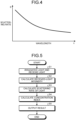
- FIG. 4 is a graph illustrating an example of the wavelength characteristics of the scattering rate with respect to an object or a substance.
- the wavelength characteristics of the scattering of light due to the minute asperity at the interfaces between the blood cells and the blood plasma at a wavelength ⁇ in the wavelength range selected as the testing light as illustrated in FIG. 4 , it is believed that the wavelength characteristics do not exhibit any peak.
- the wavelength ⁇ of the testing light for example, a wavelength equal to or greater than 950 [nm] and equal to or smaller than 1100 [nm] is used.
- the wavelength ⁇ of the testing light is equal to or greater than 1/20-th of the depth (diameter) of the blood cells.
- the diameter of the blood cells is around 10 [ ⁇ m].
- the irradiation unit 120 includes, as the light source device, a surface-emitting element having the in-plane variability of the luminance to be equal to or smaller than 10 [%].
- the light receiving unit 130 receives images of such a resolution that the images of the blood cells have distinguishable diameters.
- FIG. 5 is a flowchart for explaining an exemplary sequence of operations performed in the biological information measurement device 100.
- the controller 111 functions as the irradiation control unit 111a and the light reception control unit 111b, and controls the irradiation unit 120 to irradiate the testing light toward the biological object 200 and controls the light receiving unit 130 to receive the testing light coming from the biological object 200 (S1).
- the controller 111 functions as the detecting unit 111e and calculates the received-light intensity in the light receiving unit 130.
- the received-light intensity is, for example, the total value of the luminance values of the pixels of the light receiving element of the light receiving unit 130 (S2).
- the controller 111 calculates the scattering rate according to the received-light intensity calculated by the detecting unit 111e at S2 (S3).
- the controller 111 calculates the concentration index corresponding to the scattering rate calculated by the scattering rate calculating unit 111f at S3 (S4).
- the controller 111 functions as the output control unit 111d that controls the output unit 150 to output the concentration index (S5).
- concentration index S5
- either the value of the concentration index obtained during the concerned testing can be output, or a graph can be output that indicates the temporal change in the concentration indexes including the concentration indexes calculated during the past testing.
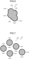
- FIGS. 6 and 7 are schematic diagrams of two-dimensional images of the blood that includes the blood plasma.
- FIG. 6 is illustrated an image indicating the state in which the blood cells are closely attached to each other
- FIG. 7 is illustrated an image indicating the state in which the blood cells are separated from each other.
- FIGS. 6 and 7 although only five blood cells are illustrated, an actual image has a large number of blood cells captured therein.
- image analysis is performed with respect to a microscopic image of the blood 210 that is taken as a sample on a prepared slide.
- image analysis as a feature quantity of the images of blood cells 210b, that is, as the boundary length of the interface between the blood cells and the blood plasma; for example, the total value of the lengths of boundaries 210b1 between the blood cells 210b and blood plasma 210a is obtained in the region onto which the light is irradiated.
- a plurality of blood cells 210b that is closely attached to each other is grouped as a singular mass in the region corresponding to the blood cells, and the length of the boundary 210b1 (edge) obtained as a result of edge detection of each such group is calculated.
- FIG. 6 is compared with FIG. 7 , it becomes clear that, in the case in which a plurality of blood cells 210b is separated from each other as illustrated in FIG. 7 , the total value of the lengths of the boundaries 210b1 is greater as compared to the case in which a plurality of blood cells 210b is closely attached to each other as illustrated in FIG. 6 .
- the total value is, for example, the total value of the lengths of a plurality of boundaries 210b1 obtained as a result of performing image analysis within a predetermined range of a two-dimensional image.
- the area of the interface between the blood cells 210b and the blood plasma 210a becomes smaller.
- the area of the interface between the blood cells and the blood plasma is equal to ⁇ n ⁇ d 2 (where n represents the number of blood cells and d represents the diameter of the blood cells).
- the area of the interface is obtained by subtracting the area of the portions of contact between the blood cells from the area of the interface ( ⁇ n ⁇ d 2 ) in the case in which the blood cells are separated from each other.
- the diameter d is obtained for the mass in which the blood cells are attached to each other; the interface area of that singular mass is calculated as ⁇ d 2 ; and that interface area can be treated as the integrated value equivalent to the number of blood cells in the light irradiation region.
- the actual area of the interface between the blood cells 210b and the blood plasma 210a increases in proportion to an increase in the total value of the lengths of the boundaries 210b1; and the actual area of the interface decreases in proportion to a decrease in the total value of the lengths of the boundaries 210b1. That is, the total value of the lengths of the boundaries 210b1 can serve as a parameter (feature quantity) corresponding to the area of the interface between the blood cells 210b and the blood plasma 210a, as well as can serve as a parameter corresponding to the scattering rate of light.
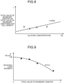
- FIG. 8 is a graph indicating the changes in the total value L of the lengths of the boundaries 210b1, which is obtained as a result of performing image analysis, in the case in which the glucose concentration in the blood undergoes changes.
- FIG. 8 it can be understood that the blood cells 210b move away from each in proportion to an increase in the glucose concentration, and accordingly there is an increase in the total value of the lengths of the boundaries 210b1 as obtained by performing image analysis.
- the boundary length L can be expressed as an approximation function g(Dg) of the glucose concentration Dg. Meanwhile, in FIG. 8 , the approximation function g(Dg) is illustrated to be a linear function. However, that is not the only possible case.
- FIG. 9 is a graph that, in the case in which the abovementioned image analysis is performed regarding a plurality of samples for which the received-light intensity is detected in the biological information measurement device 100, indicates the correlation between the total value L of the lengths of all boundaries 210b1 within the measurement range and the received-light intensity which is detected by the detecting unit 111e.
- the total value L can be a value standardized using the number of blood cells, or the area of the blood cells, or the density of the blood cells.
- a received-light intensity R decreases in inverse proportion to an increase in the total value L of the lengths of the boundaries 210b1; and that the received-light intensity R increases in inverse proportion to a decrease in the total value L of the lengths of the boundaries 210b1.
- the received-light intensity R can be expressed as an approximation function h(L) of the total value L of the lengths of the boundaries 210b1.
- the plurality of samples illustrated in FIG. 9 have different total values L of the lengths of the boundaries 210b1, that is, have different areas of the interface between the blood cells 210b and the blood plasma 210a.
- the approximation function h(L) is obtained as a result of performing regression analysis of a plurality of samples.
- the inventors of the present invention found out that, when the glucose concentration in the blood 210 is low, the total value L of the lengths of the boundaries 210b1 becomes equal to zero, that is, the boundaries 210b1 are not detected during image analysis. In that case, in the actual blood 210 too, it can be estimated that the blood cells 210b are closely attached to each other, the area of the interface is minimum, and there is either substantially no scattering or extremely less scattering of the testing light.
- the received-light intensity R in the case in which the total value L of the lengths of the boundaries 210b1 is equal to zero corresponds to the case in which the scattering light is the lowest ( ⁇ 0).
- the base received-light intensity R0 can be said to be a value calculated by extrapolating the values of a plurality of samples.
- the difference obtained by subtracting the base received-light intensity R0 from the irradiation intensity in the case of having the lowest scattering light ( ⁇ 0) is equivalent to the intensity difference based on pure absorption obtained after the elimination of the effects of the scattering of light attributed to the biological object 200, the blood 210, the blood plasma, the blood cells, glucose, and other substances such as hemoglobin. That is, the abovementioned difference is equivalent to an absorption intensity A. In this way, the absorption intensity A can be estimated.
- coefficients a and b represent the structural fluctuation at the interface between the blood cells and the blood plasma causing the scattering of light, that is, represent light scattering coefficients.
- the light scattering coefficients a and b too sometimes undergo changes due to the action with the target substance such as glucose, and can be used as concentration indexes.
- the scattering rate calculating unit 111f can subtract the received-light intensity R, which is obtained by the detecting unit 111e at each measurement timing, and the absorption intensity A (a constant value) from the irradiation intensity, and calculate the scattering intensity at each measurement timing; and can calculate the scattering rate as the ratio of the scattering intensity with respect to the irradiation intensity.
- the absorption attributed to the biological object 200, the blood 210, the blood plasma, the blood cells, glucose, and other substances can be taken into account, thereby enabling more accurate calculation of the scattering rate and in turn the concentration indexes.
- the base received-light intensity and the absorption intensity A which are used in calculating the scattering rate by taking into account the absorption, can be the values obtained by performing on an individual basis.
- the premise for obtaining the values is collecting blood in an invasive manner.
- values obtained by performing testing on some other person, or average values, or general values, or analytical values can be used in substitution.
- the biological information measurement device 100 includes, as the light receiving unit 130, an optical system for image analysis, such as an electronic microscope, and a light receiving element; apart from including an optical system for scattering detection and a light receiving element.
- the controller 111 can include a feature quantity calculating unit 111h (see FIG. 2 ) that calculates the feature quantity of an image of the blood cells 210b by performing image analysis.
- the controller 111 reads programs stored in the main memory unit 112 or the auxiliary storage device 113 and executes them so as to function as the feature quantity calculating unit 111h and the concentration index calculating unit 111g.
- the concentration index calculating unit 111g uses the approximation function g indicating the correlation illustrated in FIG. 8 or uses a map or a table, and calculates the glucose concentration Dg as the concentration index corresponding to the feature quantity calculated by the feature quantity calculating unit 111h.
- the function, or the map, or the table is stored in, for example, the auxiliary storage device 13.
- the premise is collecting blood in an invasive manner. Hence, it is desirable to perform the calculation in combination with the noninvasive testing based on the scattering intensity as explained earlier.
- the feature quantity of an image of the blood cells 210b as used during image analysis is not limited to the total value of the lengths of the boundaries 210b1.
- some other parameter can also be used, such as the number of blood cells 210b captured in a two-dimensional image, or the total value of the areas of the images of the blood cells 210b in a two-dimensional image, or the density (for example, the area density) of the images of the blood cells 210b in a two-dimensional image.
- the correlation of each feature quantity of the images of the blood cells 210b with the concentration index corresponds to the fact that the density of the blood cells 210b in the blood plasma 210a goes on decreasing in inverse proportion to an increase in the glucose concentration.
- FIG. 10 is an explanatory diagram for explaining an exemplary method for obtaining the diameter d of the blood cells 210b according to the laser diffraction/scattering method. As illustrated in FIG.
- the interface area or the length of the boundary 210b1 of the interface can be calculated from the diameter d.
- the interface area or the length of the boundary 210b1 of the interface can be calculated from the diameter d of that blood cell 210b.
- FIG. 11 is an overall configuration diagram of a biological information measurement device 100A according to a second embodiment.
- the light receiving unit 130 receives, as the testing light irradiated from the irradiation unit 120 and passing via a specimen 220, the scattering light coming from the specimen 220.
- the ratio of the scattering light receivable by the light receiving unit 130 with respect to the scattering light going out in all directions from the specimen 220 is obtained in advance, so that the scattering rate calculating unit 111f (see FIG. 2 ) becomes able to easily calculate the scattering rate of light according to the received-light intensity of the testing light received in the light receiving unit 130.
- the subsequent operations are identical to the operations according to the first embodiment explained above.
- the glucose concentration in the blood 210 can be calculated based on the scattering rate of the testing light.
- the glucose concentration can be measured with a higher degree of accuracy.
- a substance other than the blood can also be used as the test material.
- the present invention can be implemented in a biological information measurement device, a biological device measurement method, and a program.
Landscapes
- Health & Medical Sciences (AREA)
- Life Sciences & Earth Sciences (AREA)
- Chemical & Material Sciences (AREA)
- Physics & Mathematics (AREA)
- Engineering & Computer Science (AREA)
- General Health & Medical Sciences (AREA)
- Pathology (AREA)
- Analytical Chemistry (AREA)
- Biomedical Technology (AREA)
- Immunology (AREA)
- General Physics & Mathematics (AREA)
- Biochemistry (AREA)
- Dispersion Chemistry (AREA)
- Hematology (AREA)
- Molecular Biology (AREA)
- Biophysics (AREA)
- Signal Processing (AREA)
- Heart & Thoracic Surgery (AREA)
- Public Health (AREA)
- Optics & Photonics (AREA)
- Medical Informatics (AREA)
- Veterinary Medicine (AREA)
- Surgery (AREA)
- Animal Behavior & Ethology (AREA)
- Food Science & Technology (AREA)
- Medicinal Chemistry (AREA)
- Ecology (AREA)
- Urology & Nephrology (AREA)
- Clinical Laboratory Science (AREA)
- Chemical Kinetics & Catalysis (AREA)
- Spectroscopy & Molecular Physics (AREA)
- Emergency Medicine (AREA)
- Investigating Or Analysing Materials By Optical Means (AREA)
- Measurement Of The Respiration, Hearing Ability, Form, And Blood Characteristics Of Living Organisms (AREA)
- Computer Vision & Pattern Recognition (AREA)
- Investigating Or Analysing Biological Materials (AREA)
Abstract
Description
- The present invention relates to a biological information measurement device, a biological device measurement method, and a program.
- Conventionally, a method is known for noninvasive measurement of blood components using light (for example, Patent Literature 1). In the method disclosed in
Patent Literature 1, the concentration of the target substance for measurement is detected according to the absorption of light by that substance. - [Patent Literature 1]
Japanese Patent Application Laid-open No. 2005-106592 - However, in a method that makes use of the absorption of light by the target substance, such as the method disclosed in
Patent Literature 1; the scattering of light occurring due to the refractive index difference between the substances other than the target substance and the surrounding substances gets measured as noise, and that leads to a decline in the measurement accuracy. - In that regard, one of the problems to be resolved by the present invention is, for example, to provide a biological information measurement device, a biological information measurement method, and a program in a new and improved form for enabling measurement with a higher degree of accuracy.
- A biological information measurement device according to the present invention, for example, includes: a scattering rate calculating unit configured to calculate a scattering rate of light at an interface between a medium present in a biological object or in a specimen and a particle included in the medium based on received-light intensity of light irradiated onto the biological object or onto the specimen and received via the biological object or via the specimen; and a concentration index calculating unit configured to calculate, based on a correlation between the scattering rate of the light at the interface and a concentration index corresponding to concentration of a target substance that is different from the particle included in the medium, the concentration index corresponding to the scattering rate of the light calculated by the scattering rate calculating unit.
- In the biological information measurement device, the light irradiated onto the biological object or the specimen may be light of a wavelength that does not exhibit peak of the absorption rate in wavelength characteristics of absorption rates of light in the medium, the particle and the target substance.
- In the biological information measurement device, the target substance may be glucose.
- In the biological information measurement device, the medium may be blood plasma.
- In the biological information measurement device, the particle may be a blood cell.
- In the biological information measurement device, the scattering rate calculating unit may be configured to calculate the scattering rate of light at the interface between the medium present in the biological object or in the specimen and the particle included in the medium based on received-light intensity of light passed through the biological object or the specimen or based on received-light intensity of light reflected from the biological object or the specimen.
- In the biological information measurement device, the scattering rate calculating unit may be configured to calculate the scattering rate of light based on base received-light intensity that represents received-light intensity of light when scattering in the medium is minimum or substantially equal to zero.
- In the biological information measurement device, the base received-light intensity may be calculated by extrapolating correlation of received-light intensity of light with an area of interface or a boundary length of interface in a plurality of samples having different areas of interface between the particle included in the medium and the medium.
- In the biological information measurement device, as the plurality of samples having different areas of interface, a plurality of samples may be used each of which has a different feature quantity regarding the area of interface or the boundary length of interface in a particle image obtained as a result of performing image processing on a two-dimensional image of the medium including the particle and the target substance.
- In the biological information measurement device, feature quantity regarding the area of interface or the boundary length of interface in the particle image may be a total value of edge lengths of the particle images, number of the particle images, a total value of areas of the particle images, or density of the particle images in the two-dimensional image.
- In the biological information measurement device, the feature quantity regarding the area of interface or the boundary length of interface may be calculated based on a diameter of the particle measured using laser diffraction/scattering method.
- In the biological information measurement device, the scattering rate calculating unit may be configured to calculate the scattering rate of the light at the interface between the medium present in the biological object or in the specimen and the particle included in the medium based on the received-light intensity of light scattered from the biological object or the specimen.
- The biological information measurement device may include: an irradiation unit configured to irradiate a biological object or a specimen with light; a light receiving unit configured to receive the light irradiated onto the biological object or onto the specimen from the irradiation unit and passed via the biological object or via the specimen; and a detecting unit configured to detect received-light intensity of the light received by the light receiving unit.
- In the biological information measurement device, the irradiation unit may include a surface-emitting element having in-plane variability of luminance to be equal to or smaller than 10%.
- In the biological information measurement device, the irradiation unit may include a light source configured to output light having a wavelength equal to or greater than 1/20-th of a depth of the particle.
- In the biological information measurement device, the light receiving unit may be configured to receive an image having resolution in which a diameter of an image of the particle is distinguishable.
- The biological information measurement device may include a field lens configured to allow passage of light received by the light receiving unit.
- A biological information measurement method executed by a computer, for example, includes: calculating a scattering rate of light at an interface between a medium present in a biological object or in a specimen and a particle included in the medium based on received-light intensity of light irradiated onto the biological object or onto the specimen and received via the biological object or via the specimen; and calculating the concentration index as biological information calculating performing correction in form of subtracting the calculated scattering rate of light based on a correlation stored in a memory and established between the scattering rate of light at the interface and a concentration index corresponding to concentration of a target substance that is different from the particle included in the medium.
- A biological information measurement method executed by a computer, for example, includes: calculating feature quantity regarding an area of interface or a boundary length of interface in a particle image of a particle by performing image processing of a two-dimensional image of a medium of a biological object or a specimen including the particle and a target substance; and calculating a concentration index corresponding to the calculated feature quantity of the particle image based on a correlation established between the feature quantity of the particle image and concentration index corresponding to concentration of the target substance included in the medium, the correlation corresponding to a fact that density of the particle in the medium decreases in inverse proportion to an increase in concentration of the target substance.
- A biological information measurement method executed by a computer, for example, includes: calculating feature quantity regarding an area of interface or a boundary length of interface of a particle by performing laser diffraction/scattering method to a medium of a biological object or a specimen including the particle and a target substance; and calculating a concentration index corresponding to the calculated feature quantity of the particle image based on a correlation established between the feature quantity and concentration index corresponding to concentration of the target substance included in the medium, the correlation corresponding to a fact that density of the particle in the medium decreases in inverse proportion to an increase in concentration of the target substance.
- A program according to the present invention causes a computer to function as a biological information measurement device including: a scattering rate calculating unit configured to calculate a scattering rate of light at an interface between a medium present in a biological object or in a specimen and a particle included in the medium based on received-light intensity of light irradiated onto the biological object or onto the specimen and received via the biological object or via the specimen; and a concentration index calculating unit configured to calculate, based on a correlation between the scattering rate of the light at the interface and a concentration index corresponding to concentration of a target substance that is different from the particle included in the medium, the concentration index corresponding to the scattering rate of the light calculated by the scattering rate calculating unit.
- According to the present invention, it becomes possible to provide a biological information measurement device, a biological information measurement method, and a program in a new and improved form, so that the concentration of the target substance can be measured even using laser light having the wavelength not absorbable by the target substance.
-
-
FIG. 1 is an illustrative overall configuration diagram of a biological information measurement device according to a first embodiment. -
FIG. 2 is a block diagram of a control device of the biological information measurement device according to the first embodiment. -
FIG. 3 is a diagram illustrating an exemplary correlation between the scattering rate of light and a concentration index of the target substance in a test material as obtained in the biological information measurement device according to the first embodiment. -
FIG. 4 is a graph illustrating an example of the wavelength characteristics of the scattering rate of light of a test material as obtained in the biological information measurement device according to the first embodiment depending on the wavelength of light. -
FIG. 5 is a flowchart for explaining an exemplary sequence of operations performed in the biological information measurement device according to the first embodiment. -
FIG. 6 is an illustrative schematic diagram indicating the state in which particles are closely attached to each other in a two-dimensional image. -
FIG. 7 is an illustrative schematic diagram indicating the state in which particles are separated from each other in a two-dimensional image. -
FIG. 8 is a diagram illustrating an exemplary correlation between glucose concentration in a test material and the total value of boundary lengths in a two-dimensional image as obtained in the biological information measurement device according to the first embodiment. -
FIG. 9 is a graph that, in the case in which image analysis is performed regarding a plurality of samples for which the received-light intensity is detected in the biological information measurement device according to the first embodiment, indicates an exemplary correlation between the total value of boundary lengths and the received-light intensity which is detected by a detecting unit. -
FIG. 10 is an explanatory diagram for explaining an exemplary method for obtaining the diameter of the particles according to the laser diffraction/scattering method. -
FIG. 11 is an illustrative overall configuration diagram of a biological information measurement device according to a second embodiment. - Exemplary embodiments of the present invention are described below. The configurations explained in the embodiments described below as well as the actions and the results (effects) attributed to the configurations are only exemplary. Thus, the present invention can be implemented also using some different configuration than the configurations disclosed in the embodiments described below. Meanwhile, according to the present invention, it becomes possible to achieve at least one of various effects (including secondary effects) that are attributed to the configurations.
- In the present written description, the scattering of light particularly implies the case in which, only at the concerned wavelength, particles do not have a peak that results in a decline in the light transmission rate; and in which the light transmission rate either goes on continuously declining or remains at a constant value more toward the side of shorter wavelengths within a range of around ± 50 [nm] of the concerned wavelength. Moreover, there is also an occurrence of light loss at the interface between the particles and the substance. Academically, there have been reports that, at the interface of particle such as blood cells, local absorption also occurs besides the scattering. However, in practice, the loss of the transmitted light occurring at the interface is extremely difficult to isolate as scattering or absorption. In that regard, in the present written description, all of the loss attributed to the particle interface and having wavelength dependency is defined as the light loss.
- Moreover, in the present written description, the scattering rate of light indicates the proportion of the input of the attenuated light generated due to the scattering of light with respect to the intensity of "1" of the input light, as well as indicates all physical quantities that have a correlation with that proportion. For example, the scattering rate of light can be a Reyleigh scattering coefficient or a Mie scattering coefficient.
-
FIG. 1 is an overall configuration diagram of a biologicalinformation measurement device 100. As illustrated inFIG. 1 , the biologicalinformation measurement device 100 includes acontrol device 110, anirradiation unit 120, alight receiving unit 130, and afield lens 131. - The
control device 110 controls the constituent elements of the biologicalinformation measurement device 100 and, based on a testing light received by thelight receiving unit 130, carries out testing ofblood 210 included in ablood vessel 201 of abiological object 200. Herein, as an example, the glucose concentration is tested. Theblood 210 can also be referred to as a test material. In theblood 210; blood plasma, blood cells, and glucose are included. The blood plasma represents an example of a medium; the blood cells represent an example of particles; and the glucose represents an example of the target substance. - The
irradiation unit 120 irradiates thebiological object 200 with the testing light. Theirradiation unit 120 includes a light source device and an optical-system component that transmits the testing light coming from the light source device and emits it. - The
light receiving unit 130 either receives the testing light that was irradiated onto thebiological object 200 and that came from thebiological object 200. For example, thelight receiving unit 130 receives the testing light that has passed through thebiological object 200, or receives the reflected light that got reflected from thebiological object 200. For example, thelight receiving unit 130 includes a light receiving element such as a CMOS image sensor or a CCD, and includes an optical system component that transmits the testing light to the light receiving element. Meanwhile, the measurement target onto which the testing light is irradiated is not limited to thebiological object 200, and alternatively can be a specimen that includes the substances of thebiological object 200. - The
field lens 131 allows passage of the light that is input to thelight receiving unit 130 from theblood 210. As a result of using thefield lens 131, it becomes possible to enhance the resolution. -
FIG. 2 is a block diagram of the biologicalinformation measurement device 100. As illustrated inFIG. 2 , apart from including thecontrol device 110, theirradiation unit 120, and thelight receiving unit 130; the biologicalinformation measurement device 100 also includes aninput unit 140 and anoutput unit 150. Theinput unit 140 and theoutput unit 150 build a user interface for the user or the operator. For example, theinput unit 140 is an input device such as a keyboard, a touch-sensitive panel, a mouse, switches, or operation buttons. Theoutput unit 150 is an output device such as a display, a printer, a lamp, or a speaker that performs output in the form of images, printed material, or sounds. - The
control device 110 includes a controller 111, a main memory unit 112, and anauxiliary storage device 113. - The controller 111 is, for example, a processor (circuit) such as a central processing unit (CPU). The main memory unit 112 is, for example, a random access memory (RAM) or a read only memory (ROM). The
auxiliary storage device 113 is a nonvolatile storage device such as a solid state drive (SSD) or a hard disk drive (HDD). - The controller 111 reads programs stored in the main memory unit 112 or the
auxiliary storage device 113 and executes them so as to function as an irradiation control unit 111a, a light reception control unit 111b, aninput control unit 111c, an output control unit 111d, a detectingunit 111e, a scatteringrate calculating unit 111f, and a concentrationindex calculating unit 111g. The programs are installable files or executable files that can be recorded in a computer-readable recording medium. The recording medium can also be referred to as a program product. Meanwhile, the programs, the values used in the arithmetic processing performed in the processor, or information such as maps and tables can be stored in advance in the main memory unit 112 or theauxiliary storage device 113, or can be stored in a computer connected to a communication network and downloaded and stored in theauxiliary storage device 113 via the communication network. Theauxiliary storage device 113 is used to store the data written by the processor. Meanwhile, the arithmetic processing performed by the controller 111 can at least partially be implemented using hardware. In that case, the controller 111 can include, for example, an FPGA (Field Programmable Gate Array) or an ASIC (Application Specific Integrated Circuit). - The irradiation control unit 111a controls the
irradiation unit 120 so as to ensure the output of a predetermined testing light. - The light reception control unit 111b controls the
light receiving unit 130 so as to ensure the reception of the testing light. - The
input control unit 111c receives input signals from theinput unit 140. Moreover, theinput control unit 111c can control theinput unit 140 so as to enable predetermined input operations. - The output control unit 111d controls the
output unit 150 so as to ensure a predetermined output. - The inventors of the present invention did a thorough study and found out that, accompanying an increase in the glucose concentration in the blood, there is an increase in the scattering rate of light in the blood. When light is irradiated onto the blood, due to different refractive indexes of the blood plasma and the blood cells, the light gets scattered at the surface of the blood cells, that is, at the minute asperity of the interfaces representing the boundaries between the blood cells and the blood plasma. Hence, when light is irradiated onto the blood cells, greater the area of the interfaces, the greater is the scattering of the light. The inventors of the present invention focused on that phenomenon and did a thorough study to find the following: (1) in the abutting portion of two blood cells, since there is no refractive index difference, there is almost no scattering of light; (2) when the glucose concentration is low, the blood cells in the blood remain abutted against each other, so that the interface remains small in area and the scattering of light is less; and (3) as the glucose concentration in the blood increases, the blood cells in the blood move away from each other thereby resulting in an increase in the area of the interface, and accordingly the scattering of light increases. The separation of the blood cells accompanying an increase in the glucose concentration is inferred to be caused by the negative charging of the blood cells.
- Using such a phenomenon found out by the inventors of the present invention, in order to calculate the glucose concentration in the
blood 210 based on the scattering of light occurring in theblood 210, the controller 111 according to a first embodiment includes the detectingunit 111e, the scatteringrate calculating unit 111f, and the concentrationindex calculating unit 111g. - The detecting
unit 111e calculates the received-light intensity as the total value of the luminance values of the pixels of the light receiving element of thelight receiving unit 130. - The scattering
rate calculating unit 111f calculates the scattering rate as, for example, the ratio of the scattering intensity with respect to the irradiating intensity. The irradiating intensity can be considered as the sum of the transmission intensity or the reflection intensity, the absorption intensity, and the scattering intensity. Since the received-light intensity is the intensity of the transmitted light or the reflected light, the scattering intensity can be calculated by subtracting the received-light intensity and the absorption intensity from the irradiating intensity. Herein, the absorption intensity represents the intensity of the testing light that is absorbed in thebiological object 200, and can be estimated according to a method explained later. The absorption intensity can be obtained in advance and stored in, for example, theauxiliary storage device 113 as a numerical value or a function in a program or as the data referred to by a program. - The concentration
index calculating unit 111g calculates a concentration index, which corresponds to the scattering rate calculated at the scatteringrate calculating unit 111f, based on the pre-obtained correlation between the scattering rate and the concentration index. Herein, the concentration index represents a value serving as the index of the glucose concentration, and either can be the glucose concentration itself or can be a relative value that increases in proportion to an increase in the glucose concentration. The concentration index can be set as an individual value for each person or can be set as a common value for a plurality of persons. Moreover, during the follow-up, as long as the concentration index gives a rough indication of the increase and decrease in the glucose concentration, it serves the purpose. -
FIG. 3 is a diagram illustrating an exemplary correlation between a scattering rate S and a concentration index D. As explained above, as a result of the research done by the inventors of the present invention, it became clear that the glucose concentration increases in proportion to an increase in the scattering rate S of the testing light. From the test results obtained regarding a plurality of samples, it became clear that the concentration index D corresponding to the glucose concentration can be expressed as an approximation function f(S) of the testing light. Meanwhile, inFIG. 3 , the approximation function f(S) is illustrated to be a linear function. However, that is not the only possible case. The correlation explained above is obtained in advance and is stored as a function, or a map, or a table in, for example, theauxiliary storage device 113. - In order to perform the measurement based on the new knowledge mentioned above, it is desirable that the testing light output from the
irradiation unit 120 is of a wavelength that has a low rate of absorption in thebiological object 200, theblood 210, the blood plasma, the blood cells, and the glucose.FIG. 4 is a graph illustrating an example of the wavelength characteristics of the scattering rate with respect to an object or a substance. Regarding the wavelength characteristics of the scattering of light due to the minute asperity at the interfaces between the blood cells and the blood plasma, at a wavelength λ in the wavelength range selected as the testing light as illustrated inFIG. 4 , it is believed that the wavelength characteristics do not exhibit any peak. As the wavelength λ of the testing light, for example, a wavelength equal to or greater than 950 [nm] and equal to or smaller than 1100 [nm] is used. - Moreover, in order to ensure that the testing light does not get optically coupled with the blood cells, it is desirable that the wavelength λ of the testing light is equal to or greater than 1/20-th of the depth (diameter) of the blood cells. The diameter of the blood cells is around 10 [µm].
- Moreover, in order to perform the measurement, it is desirable that the
irradiation unit 120 includes, as the light source device, a surface-emitting element having the in-plane variability of the luminance to be equal to or smaller than 10 [%]. - Furthermore, it is desirable that the
light receiving unit 130 receives images of such a resolution that the images of the blood cells have distinguishable diameters. -
FIG. 5 is a flowchart for explaining an exemplary sequence of operations performed in the biologicalinformation measurement device 100. As illustrated inFIG. 5 , firstly, the controller 111 functions as the irradiation control unit 111a and the light reception control unit 111b, and controls theirradiation unit 120 to irradiate the testing light toward thebiological object 200 and controls thelight receiving unit 130 to receive the testing light coming from the biological object 200 (S1). - Then, the controller 111 functions as the detecting
unit 111e and calculates the received-light intensity in thelight receiving unit 130. The received-light intensity is, for example, the total value of the luminance values of the pixels of the light receiving element of the light receiving unit 130 (S2). - Subsequently, the controller 111 calculates the scattering rate according to the received-light intensity calculated by the detecting
unit 111e at S2 (S3). - Then, based on the correlation between the scattering rate and the concentration index as illustrated in
FIG. 3 , the controller 111 calculates the concentration index corresponding to the scattering rate calculated by the scatteringrate calculating unit 111f at S3 (S4). - Subsequently, the controller 111 functions as the output control unit 111d that controls the
output unit 150 to output the concentration index (S5). At S5, either the value of the concentration index obtained during the concerned testing can be output, or a graph can be output that indicates the temporal change in the concentration indexes including the concentration indexes calculated during the past testing. In the case of performing such operations, every time the scattering rate is calculated at S3, it can be stored in theauxiliary storage device 113 in a corresponding manner to the ID of the subject being tested and the measurement date and time; and the output control unit 111d can refer to the stored information and generate output information to be output from theoutput unit 150. - The inventors of the present invention found out that the absorption intensity of the light in the
blood 210 can be estimated based on the analysis of a two-dimensional image of the blood that includes the blood plasma.FIGS. 6 and 7 are schematic diagrams of two-dimensional images of the blood that includes the blood plasma. InFIG. 6 is illustrated an image indicating the state in which the blood cells are closely attached to each other, and inFIG. 7 is illustrated an image indicating the state in which the blood cells are separated from each other. Meanwhile, inFIGS. 6 and 7 , although only five blood cells are illustrated, an actual image has a large number of blood cells captured therein. - Apart from the measurement performed by the biological
information measurement device 100; for example, image analysis is performed with respect to a microscopic image of theblood 210 that is taken as a sample on a prepared slide. In the image analysis, as a feature quantity of the images ofblood cells 210b, that is, as the boundary length of the interface between the blood cells and the blood plasma; for example, the total value of the lengths of boundaries 210b1 between theblood cells 210b andblood plasma 210a is obtained in the region onto which the light is irradiated. In that case, for example, a plurality ofblood cells 210b that is closely attached to each other is grouped as a singular mass in the region corresponding to the blood cells, and the length of the boundary 210b1 (edge) obtained as a result of edge detection of each such group is calculated. Thus, ifFIG. 6 is compared withFIG. 7 , it becomes clear that, in the case in which a plurality ofblood cells 210b is separated from each other as illustrated inFIG. 7 , the total value of the lengths of the boundaries 210b1 is greater as compared to the case in which a plurality ofblood cells 210b is closely attached to each other as illustrated inFIG. 6 . Thus, the total value is, for example, the total value of the lengths of a plurality of boundaries 210b1 obtained as a result of performing image analysis within a predetermined range of a two-dimensional image. As explained above, when a plurality ofblood cells 210b is closely attached to each other, the area of the interface between theblood cells 210b and theblood plasma 210a becomes smaller. When the blood cells are separated from each other, the area of the interface between the blood cells and the blood plasma is equal to π·n·d2 (where n represents the number of blood cells and d represents the diameter of the blood cells). On the other hand, when the blood cells are attached to each other, the area of the interface is obtained by subtracting the area of the portions of contact between the blood cells from the area of the interface (π·n·d2) in the case in which the blood cells are separated from each other. Approximatively, the diameter d is obtained for the mass in which the blood cells are attached to each other; the interface area of that singular mass is calculated as π·d2; and that interface area can be treated as the integrated value equivalent to the number of blood cells in the light irradiation region. In the image analysis, the actual area of the interface between theblood cells 210b and theblood plasma 210a increases in proportion to an increase in the total value of the lengths of the boundaries 210b1; and the actual area of the interface decreases in proportion to a decrease in the total value of the lengths of the boundaries 210b1. That is, the total value of the lengths of the boundaries 210b1 can serve as a parameter (feature quantity) corresponding to the area of the interface between theblood cells 210b and theblood plasma 210a, as well as can serve as a parameter corresponding to the scattering rate of light. - In practice, it was found out that, regarding a glucose concentration Dg and a total value L of the lengths of all boundaries 210b1 within the measurement range being irradiated with light, the correlation is as illustrated in
FIG. 8 . Herein,FIG. 8 is a graph indicating the changes in the total value L of the lengths of the boundaries 210b1, which is obtained as a result of performing image analysis, in the case in which the glucose concentration in the blood undergoes changes. By referring toFIG. 8 , it can be understood that theblood cells 210b move away from each in proportion to an increase in the glucose concentration, and accordingly there is an increase in the total value of the lengths of the boundaries 210b1 as obtained by performing image analysis. The boundary length L can be expressed as an approximation function g(Dg) of the glucose concentration Dg. Meanwhile, inFIG. 8 , the approximation function g(Dg) is illustrated to be a linear function. However, that is not the only possible case. -
FIG. 9 is a graph that, in the case in which the abovementioned image analysis is performed regarding a plurality of samples for which the received-light intensity is detected in the biologicalinformation measurement device 100, indicates the correlation between the total value L of the lengths of all boundaries 210b1 within the measurement range and the received-light intensity which is detected by the detectingunit 111e. At that time, the total value L can be a value standardized using the number of blood cells, or the area of the blood cells, or the density of the blood cells. By referring toFIG. 9 , it can be understood that a received-light intensity R decreases in inverse proportion to an increase in the total value L of the lengths of the boundaries 210b1; and that the received-light intensity R increases in inverse proportion to a decrease in the total value L of the lengths of the boundaries 210b1. The received-light intensity R can be expressed as an approximation function h(L) of the total value L of the lengths of the boundaries 210b1. The plurality of samples illustrated inFIG. 9 have different total values L of the lengths of the boundaries 210b1, that is, have different areas of the interface between theblood cells 210b and theblood plasma 210a. The approximation function h(L) is obtained as a result of performing regression analysis of a plurality of samples. - The inventors of the present invention found out that, when the glucose concentration in the
blood 210 is low, the total value L of the lengths of the boundaries 210b1 becomes equal to zero, that is, the boundaries 210b1 are not detected during image analysis. In that case, in theactual blood 210 too, it can be estimated that theblood cells 210b are closely attached to each other, the area of the interface is minimum, and there is either substantially no scattering or extremely less scattering of the testing light. - That is, the received-light intensity R in the case in which the total value L of the lengths of the boundaries 210b1 is equal to zero, that is, a received-light intensity R0=h(0) (hereinafter, the received-light intensity R0 is treated as the base received-light intensity) corresponds to the case in which the scattering light is the lowest (≈0). The base received-light intensity R0 can be said to be a value calculated by extrapolating the values of a plurality of samples.
- The difference obtained by subtracting the base received-light intensity R0 from the irradiation intensity in the case of having the lowest scattering light (≈0) is equivalent to the intensity difference based on pure absorption obtained after the elimination of the effects of the scattering of light attributed to the
biological object 200, theblood 210, the blood plasma, the blood cells, glucose, and other substances such as hemoglobin. That is, the abovementioned difference is equivalent to an absorption intensity A. In this way, the absorption intensity A can be estimated. Meanwhile, if the approximation is performed as a quadratic function such as a function h(L)=a×L2×b×L+c, coefficients a and b represent the structural fluctuation at the interface between the blood cells and the blood plasma causing the scattering of light, that is, represent light scattering coefficients. The light scattering coefficients a and b too sometimes undergo changes due to the action with the target substance such as glucose, and can be used as concentration indexes. - Thus, the scattering
rate calculating unit 111f can subtract the received-light intensity R, which is obtained by the detectingunit 111e at each measurement timing, and the absorption intensity A (a constant value) from the irradiation intensity, and calculate the scattering intensity at each measurement timing; and can calculate the scattering rate as the ratio of the scattering intensity with respect to the irradiation intensity. As a result of performing such arithmetic processing, the absorption attributed to thebiological object 200, theblood 210, the blood plasma, the blood cells, glucose, and other substances can be taken into account, thereby enabling more accurate calculation of the scattering rate and in turn the concentration indexes. - Meanwhile, the base received-light intensity and the absorption intensity A, which are used in calculating the scattering rate by taking into account the absorption, can be the values obtained by performing on an individual basis. However, the premise for obtaining the values is collecting blood in an invasive manner. Alternatively, values obtained by performing testing on some other person, or average values, or general values, or analytical values can be used in substitution.
- Meanwhile, by referring to the graph illustrated in
FIG. 8 , it can be understood that, based on the correlation between a feature quantity of an image of theblood cells 210b, which is obtained by performing image analysis, and the glucose concentration (the concentration index), the glucose concentration can be calculated from the feature quantity of the image. In order to calculate the glucose concentration based on the correlation illustrated inFIG. 8 , the biologicalinformation measurement device 100 includes, as thelight receiving unit 130, an optical system for image analysis, such as an electronic microscope, and a light receiving element; apart from including an optical system for scattering detection and a light receiving element. Moreover, the controller 111 can include a featurequantity calculating unit 111h (seeFIG. 2 ) that calculates the feature quantity of an image of theblood cells 210b by performing image analysis. In that case, the controller 111 reads programs stored in the main memory unit 112 or theauxiliary storage device 113 and executes them so as to function as the featurequantity calculating unit 111h and the concentrationindex calculating unit 111g. The concentrationindex calculating unit 111g uses the approximation function g indicating the correlation illustrated inFIG. 8 or uses a map or a table, and calculates the glucose concentration Dg as the concentration index corresponding to the feature quantity calculated by the featurequantity calculating unit 111h. Herein, the function, or the map, or the table is stored in, for example, the auxiliary storage device 13. However, regarding such calculation of the concentration index that corresponds to the feature quantity and that is based on image analysis, the premise is collecting blood in an invasive manner. Hence, it is desirable to perform the calculation in combination with the noninvasive testing based on the scattering intensity as explained earlier. - Meanwhile, the feature quantity of an image of the
blood cells 210b as used during image analysis is not limited to the total value of the lengths of the boundaries 210b1. Alternatively, some other parameter can also be used, such as the number ofblood cells 210b captured in a two-dimensional image, or the total value of the areas of the images of theblood cells 210b in a two-dimensional image, or the density (for example, the area density) of the images of theblood cells 210b in a two-dimensional image. The correlation of each feature quantity of the images of theblood cells 210b with the concentration index corresponds to the fact that the density of theblood cells 210b in theblood plasma 210a goes on decreasing in inverse proportion to an increase in the glucose concentration. For example, higher the concentration of glucose, the greater is the decrease in the number ofblood cells 210b in the two-dimensional image, the greater is the decrease in the total value of the areas of theblood cells 210b in the two-dimensional image, and the greater is the decrease in the density of the images of theblood cells 210b in the two-dimensional image. - As a method for obtaining information about the interface area or the boundary length of the interface of the particles in biological objects such as blood cells, it is possible to implement a laser diffraction/scattering method. In that method, different intensity patterns are observed according to the angles of the scattering light, and particle size distribution is obtained using the Mie scattering theory. This method is a widely-used technology in the measurement field.
FIG. 10 is an explanatory diagram for explaining an exemplary method for obtaining the diameter d of theblood cells 210b according to the laser diffraction/scattering method. As illustrated inFIG. 10 , for example, when theblood cells 210b are closely attached to each other thereby forming a mass, that mass can approximated to aparticle 210p and the diameter d can be calculated, and the interface area or the length of the boundary 210b1 of the interface can be calculated from the diameter d. Meanwhile, when there is only oneblood cell 210b, the interface area or the length of the boundary 210b1 of the interface can be calculated from the diameter d of thatblood cell 210b. -
FIG. 11 is an overall configuration diagram of a biologicalinformation measurement device 100A according to a second embodiment. As illustrated inFIG. 11 , in the second embodiment, thelight receiving unit 130 receives, as the testing light irradiated from theirradiation unit 120 and passing via aspecimen 220, the scattering light coming from thespecimen 220. In that case, the ratio of the scattering light receivable by thelight receiving unit 130 with respect to the scattering light going out in all directions from thespecimen 220 is obtained in advance, so that the scatteringrate calculating unit 111f (seeFIG. 2 ) becomes able to easily calculate the scattering rate of light according to the received-light intensity of the testing light received in thelight receiving unit 130. The subsequent operations are identical to the operations according to the first embodiment explained above. - As explained above, according to the second embodiment, the glucose concentration in the
blood 210 can be calculated based on the scattering rate of the testing light. With such a configuration, if the scattering rate of the testing light is used, the glucose concentration can be measured with a higher degree of accuracy. - While certain embodiments have been described, these embodiments and modification examples have been presented by way of example only, and are not intended to limit the scope of the inventions. Indeed, the novel embodiments described herein may be embodied in a variety of other forms; furthermore, various omissions, substitutions and changes in the form of the embodiments described herein may be made without departing from the spirit of the inventions. The accompanying claims and their equivalents are intended to cover such forms or modifications as would fall within the scope and spirit of the inventions. Moreover, regarding the constituent elements, the specifications about the configurations and the shapes (structure, type, direction, shape, size, length, width, thickness, height, number, arrangement, position, material, etc.) can be suitably modified.
- For example, a substance other than the blood can also be used as the test material.
- The present invention can be implemented in a biological information measurement device, a biological device measurement method, and a program.
-
- 100, 100A biological information measurement device
- 110 control device
- 111 controller
- 111a irradiation control unit
- 111b light reception control unit
- 111c input control unit
- 111d output control unit
- 111e detecting unit
- 111f scattering rate calculating unit
- 111g concentration index calculating unit
- 111h feature quantity calculating unit
- 112 main memory unit
- 113 auxiliary storage device
- 120 irradiation unit
- 130 light receiving unit
- 131 field lens
- 140 input unit
- 150 output unit
- 200 biological object
- 201 blood vessel
- 210 blood
- 201a blood plasma (medium)
- 210b blood cell (particle)
- 210b1 boundary
- 210p particle
- 220 specimen
- D concentration index
- Dg glucose concentration
- L total value (of boundary lengths), or total value (of boundary lengths)/blood cell density
- S scattering rate
- R received-light intensity
- R0 base received-light intensity
- λ wavelength
Claims (21)
- A biological information measurement device comprising:a scattering rate calculating unit configured to calculate a scattering rate of light at an interface between a medium present in a biological object or in a specimen and a particle included in the medium based on received-light intensity of light irradiated onto the biological object or onto the specimen and received via the biological object or via the specimen; anda concentration index calculating unit configured to calculate, based on a correlation between the scattering rate of the light at the interface and a concentration index corresponding to concentration of a target substance that is different from the particle included in the medium, the concentration index corresponding to the scattering rate of the light calculated by the scattering rate calculating unit.
- The biological information measurement device according to claim 1, wherein the light irradiated onto the biological object or the specimen is light of a wavelength that does not exhibit peak of the absorption rate in wavelength characteristics of absorption rates of light in the medium, the particle and the target substance.
- The biological information measurement device according to claim 1 or 2, wherein the target substance is glucose.
- The biological information measurement device according to any one of claims 1 to 3, wherein the medium is blood plasma.
- The biological information measurement device according to any one of claims 1 to 4, wherein the particle is a blood cell.
- The biological information measurement device according to any one of claims 1 to 5, wherein the scattering rate calculating unit is configured to calculate the scattering rate of light at the interface between the medium present in the biological object or in the specimen and the particle included in the medium based on received-light intensity of light passed through the biological object or the specimen or based on received-light intensity of light reflected from the biological object or the specimen.
- The biological information measurement device according to any one of claims 1 to 5, wherein the scattering rate calculating unit is configured to calculate the scattering rate of light based on base received-light intensity that represents received-light intensity of light when scattering in the medium is minimum or substantially equal to zero.
- The biological information measurement device according to claim 7, wherein the base received-light intensity is calculated by extrapolating correlation of received-light intensity of light with an area of interface or a boundary length of interface in a plurality of samples having different areas of interface between the particle included in the medium and the medium.
- The biological information measurement device according to claim 8, wherein, as the plurality of samples having different areas of interface, a plurality of samples are used each of which has a different feature quantity regarding the area of interface or the boundary length of interface in a particle image obtained as a result of performing image processing on a two-dimensional image of the medium including the particle and the target substance.
- The biological information measurement device according to claim 9, wherein feature quantity regarding the area of interface or the boundary length of interface in the particle image is a total value of edge lengths of the particle images, number of the particle images, a total value of areas of the particle images, or density of the particle images in the two-dimensional image.
- The biological information measurement device according to claim 8, wherein the feature quantity regarding the area of interface or the boundary length of interface is calculated based on a diameter of the particle measured using laser diffraction/scattering method.
- The biological information measurement device according to any one of claims 1 to 5, wherein the scattering rate calculating unit is configured to calculate the scattering rate of the light at the interface between the medium present in the biological object or in the specimen and the particle included in the medium based on the received-light intensity of light scattered from the biological object or the specimen.
- The biological information measurement device according to any one of claims 1 to 12, further comprising:an irradiation unit configured to irradiate a biological object or a specimen with light;a light receiving unit configured to receive the light irradiated onto the biological object or onto the specimen from the irradiation unit and passed via the biological object or via the specimen; anda detecting unit configured to detect received-light intensity of the light received by the light receiving unit.
- The biological information measurement device according to claim 13, wherein the irradiation unit includes a surface-emitting element having in-plane variability of luminance to be equal to or smaller than 10%.
- The biological information measurement device according to claim 13 or 14, wherein the irradiation unit includes a light source configured to output light having a wavelength equal to or greater than 1/20-th of a depth of the particle.
- The biological information measurement device according to any one of claims 13 to 15, wherein the light receiving unit is configured to receive an image having resolution in which a diameter of an image of the particle is distinguishable.
- The biological information measurement device according to any one of claims 13 to 16, further comprising a field lens configured to allow passage of light received by the light receiving unit.
- A biological information measurement method executed by a computer, the method comprising:calculating a scattering rate of light at an interface between a medium present in a biological object or in a specimen and a particle included in the medium based on received-light intensity of light irradiated onto the biological object or onto the specimen and received via the biological object or via the specimen; andcalculating the concentration index as biological information calculating performing correction in form of subtracting the calculated scattering rate of light based on a correlation stored in a memory and established between the scattering rate of light at the interface and a concentration index corresponding to concentration of a target substance that is different from the particle included in the medium.
- A biological information measurement method executed by a computer, the method comprising:calculating feature quantity regarding an area of interface or a boundary length of interface in a particle image of a particle by performing image processing of a two-dimensional image of a medium of a biological object or a specimen including the particle and a target substance; andcalculating a concentration index corresponding to the calculated feature quantity of the particle image based on a correlation established between the feature quantity of the particle image and concentration index corresponding to concentration of the target substance included in the medium, the correlation corresponding to a fact that density of the particle in the medium decreases in inverse proportion to an increase in concentration of the target substance.
- A biological information measurement method executed by a computer, the method comprising:calculating feature quantity regarding an area of interface or a boundary length of interface of a particle by performing laser diffraction/scattering method to a medium of a biological object or a specimen including the particle and a target substance; andcalculating a concentration index corresponding to the calculated feature quantity of the particle image based on a correlation established between the feature quantity and concentration index corresponding to concentration of the target substance included in the medium, the correlation corresponding to a fact that density of the particle in the medium decreases in inverse proportion to an increase in concentration of the target substance.
- A program that causes a computer to function as a biological information measurement device including:a scattering rate calculating unit configured to calculate a scattering rate of light at an interface between a medium present in a biological object or in a specimen and a particle included in the medium based on received-light intensity of light irradiated onto the biological object or onto the specimen and received via the biological object or via the specimen; anda concentration index calculating unit configured to calculate, based on a correlation between the scattering rate of the light at the interface and a concentration index corresponding to concentration of a target substance that is different from the particle included in the medium, the concentration index corresponding to the scattering rate of the light calculated by the scattering rate calculating unit.
Applications Claiming Priority (2)
| Application Number | Priority Date | Filing Date | Title |
|---|---|---|---|
| JP2021024344 | 2021-02-18 | ||
| PCT/JP2022/006499 WO2022176965A1 (en) | 2021-02-18 | 2022-02-17 | Biological information measurement device, biological information measurement method, and program |
Publications (2)
| Publication Number | Publication Date |
|---|---|
| EP4296668A1 true EP4296668A1 (en) | 2023-12-27 |
| EP4296668A4 EP4296668A4 (en) | 2025-05-07 |
Family
ID=82930722
Family Applications (1)
| Application Number | Title | Priority Date | Filing Date |
|---|---|---|---|
| EP22756282.4A Pending EP4296668A4 (en) | 2021-02-18 | 2022-02-17 | DEVICE FOR MEASURING BIOLOGICAL INFORMATION, METHOD FOR MEASURING BIOLOGICAL INFORMATION AND PROGRAM |
Country Status (6)
| Country | Link |
|---|---|
| US (1) | US20230393117A1 (en) |
| EP (1) | EP4296668A4 (en) |
| JP (1) | JP7889809B2 (en) |
| CN (1) | CN116867433A (en) |
| TW (1) | TW202242408A (en) |
| WO (1) | WO2022176965A1 (en) |
Family Cites Families (12)
| Publication number | Priority date | Publication date | Assignee | Title |
|---|---|---|---|---|
| US6329139B1 (en) * | 1995-04-25 | 2001-12-11 | Discovery Partners International | Automated sorting system for matrices with memory |
| JP2005106592A (en) | 2003-09-30 | 2005-04-21 | Aime Technology Co Ltd | Blood sugar measuring method and its device |
| JP4269079B2 (en) * | 2004-11-01 | 2009-05-27 | 株式会社エイムテクノロジー | Non-invasive measuring device for trace component concentration in scattering medium |
| EP1875203B1 (en) * | 2004-12-13 | 2011-05-04 | Bayer HealthCare LLC | Transmission spectroscopy system for use in the determination of analytes in body fluid |
| JP5303851B2 (en) * | 2007-04-03 | 2013-10-02 | 株式会社島津製作所 | Alcohol detection device |
| KR101040653B1 (en) * | 2009-01-21 | 2011-06-10 | 서울대학교산학협력단 | Non-contact optical volume pulse wave measuring device, oxygen saturation measuring device and blood pressure measuring device using the same |
| CN103347550A (en) * | 2010-11-17 | 2013-10-09 | 弗雷泽纽斯医疗保健控股公司 | Sensor clip assembly for optical monitoring system |
| JP5990905B2 (en) * | 2011-12-19 | 2016-09-14 | ソニー株式会社 | Measuring device, measuring method, program, and recording medium |
| EP2930495B1 (en) * | 2012-12-06 | 2020-08-19 | Medical Photonics Co., Ltd. | Non-invasive biolipid metabolism measuring device, non-invasive method for measuring biolipid concentration |
| KR101512076B1 (en) * | 2014-04-29 | 2015-04-14 | 길영준 | Method and Device for blood sugar estimation using Multiple Bio Signal |
| US10506989B2 (en) * | 2014-09-05 | 2019-12-17 | Phc Holdings Corporation | Method for quantifying glucose concentration and glucose concentration measurement device |
| CN107468209B (en) * | 2016-06-07 | 2021-10-08 | 松下知识产权经营株式会社 | camera |
-
2022
- 2022-02-16 TW TW111105555A patent/TW202242408A/en unknown
- 2022-02-17 EP EP22756282.4A patent/EP4296668A4/en active Pending
- 2022-02-17 WO PCT/JP2022/006499 patent/WO2022176965A1/en not_active Ceased
- 2022-02-17 JP JP2023500934A patent/JP7889809B2/en active Active
- 2022-02-17 CN CN202280015154.0A patent/CN116867433A/en active Pending
-
2023
- 2023-08-16 US US18/450,628 patent/US20230393117A1/en active Pending
Also Published As
| Publication number | Publication date |
|---|---|
| CN116867433A (en) | 2023-10-10 |
| US20230393117A1 (en) | 2023-12-07 |
| WO2022176965A1 (en) | 2022-08-25 |
| JPWO2022176965A1 (en) | 2022-08-25 |
| JP7889809B2 (en) | 2026-07-14 |
| TW202242408A (en) | 2022-11-01 |
| EP4296668A4 (en) | 2025-05-07 |
Similar Documents
| Publication | Publication Date | Title |
|---|---|---|
| KR102479862B1 (en) | Particle Analysis Method | |
| JP6559555B2 (en) | Optical measurement method and apparatus | |
| US11137339B2 (en) | Method for performing a blood count and determining the morphology of a blood smear | |
| JP6611716B2 (en) | Analytical methods to support classification | |
| JP6798625B2 (en) | Quantitative phase image generation method, quantitative phase image generator and program | |
| JP2013531787A (en) | Holographic fluctuation microscope apparatus and method for determining particle motility and / or cell dispersion | |
| KR102042864B1 (en) | Method to determine the absorption coefficient in turbid media | |
| US11530434B2 (en) | Cell mass evaluation method and device for analyzing state of cell mass | |
| WO2016080442A1 (en) | Quality evaluation method and quality evaluation device | |
| EP3786611B1 (en) | Particle size distribution measuring device and program for particle size distribution measuring device | |
| JP5883233B2 (en) | Scanning microscopic light scattering measurement and analysis apparatus and light scattering analysis method | |
| US20230393117A1 (en) | Biological information measurement device, biological information measurement method, and computer-readable recording medium | |
| JP7473200B2 (en) | Dynamic light scattering measurement device, dynamic light scattering measurement/analysis method, and measurement/analysis program | |
| Maltsev et al. | Optics of white blood cells: optical models, simulations, and experiments | |
| EP1464966A1 (en) | Apparatus and method for determining the concentration and motility of light scattering particles | |
| Bortolato et al. | New insights into the analysis of red blood cells from leukemia and anemia patients: Nonlinear quantifiers, fractal mathematics, and Wavelet Transform | |
| GB2546362A (en) | Sample analyzer and recording medium recording sample analysis program | |
| JP7848143B2 (en) | Optical measuring device | |
| EP4339591A1 (en) | Feature amount calculation device, feature amount calculation method, and program | |
| JP7504460B2 (en) | Dynamic light scattering measurement device, dynamic light scattering measurement/analysis method, and measurement/analysis program | |
| JP2021089244A (en) | Image generation device and image processing system | |
| Valero et al. | Diluted chemical identification by total internal reflection photonic sensing | |
| JPH0743249B2 (en) | Polymer spherulite analysis method and apparatus | |
| Cannaday | Improved time-lapsed angular scattering microscopy of single cells | |
| JP7191137B2 (en) | Nanoprotrusion structure inspection device and nanoprotrusion structure inspection method |
Legal Events
| Date | Code | Title | Description |
|---|---|---|---|
| STAA | Information on the status of an ep patent application or granted ep patent |
Free format text: STATUS: THE INTERNATIONAL PUBLICATION HAS BEEN MADE |
|
| PUAI | Public reference made under article 153(3) epc to a published international application that has entered the european phase |
Free format text: ORIGINAL CODE: 0009012 |
|
| STAA | Information on the status of an ep patent application or granted ep patent |
Free format text: STATUS: REQUEST FOR EXAMINATION WAS MADE |
|
| 17P | Request for examination filed |
Effective date: 20230817 |
|
| AK | Designated contracting states |
Kind code of ref document: A1 Designated state(s): AL AT BE BG CH CY CZ DE DK EE ES FI FR GB GR HR HU IE IS IT LI LT LU LV MC MK MT NL NO PL PT RO RS SE SI SK SM TR |
|
| DAV | Request for validation of the european patent (deleted) | ||
| DAX | Request for extension of the european patent (deleted) | ||
| A4 | Supplementary search report drawn up and despatched |
Effective date: 20250404 |
|
| RIC1 | Information provided on ipc code assigned before grant |
Ipc: A61B 5/1455 20060101ALI20250331BHEP Ipc: G01N 21/17 20060101ALI20250331BHEP Ipc: G01N 33/49 20060101AFI20250331BHEP |