EP4296659A1 - Electrolyte analysis apparatus - Google Patents
Electrolyte analysis apparatus Download PDFInfo
- Publication number
- EP4296659A1 EP4296659A1 EP21926752.3A EP21926752A EP4296659A1 EP 4296659 A1 EP4296659 A1 EP 4296659A1 EP 21926752 A EP21926752 A EP 21926752A EP 4296659 A1 EP4296659 A1 EP 4296659A1
- Authority
- EP
- European Patent Office
- Prior art keywords
- electrode
- flow passage
- switching unit
- passage member
- electrode group
- Prior art date
- Legal status (The legal status is an assumption and is not a legal conclusion. Google has not performed a legal analysis and makes no representation as to the accuracy of the status listed.)
- Granted
Links
Images




Classifications
-
- G—PHYSICS
- G01—MEASURING; TESTING
- G01N—INVESTIGATING OR ANALYSING MATERIALS BY DETERMINING THEIR CHEMICAL OR PHYSICAL PROPERTIES
- G01N27/00—Investigating or analysing materials by the use of electric, electrochemical, or magnetic means
- G01N27/26—Investigating or analysing materials by the use of electric, electrochemical, or magnetic means by investigating electrochemical variables; by using electrolysis or electrophoresis
- G01N27/403—Cells and electrode assemblies
- G01N27/406—Cells and probes with solid electrolytes
- G01N27/411—Cells and probes with solid electrolytes for investigating or analysing of liquid metals
- G01N27/4115—Composition or fabrication of the electrodes and coatings thereon, e.g. catalysts
- G01N27/4117—Reference electrodes or reference mixtures
-
- G—PHYSICS
- G01—MEASURING; TESTING
- G01N—INVESTIGATING OR ANALYSING MATERIALS BY DETERMINING THEIR CHEMICAL OR PHYSICAL PROPERTIES
- G01N27/00—Investigating or analysing materials by the use of electric, electrochemical, or magnetic means
- G01N27/26—Investigating or analysing materials by the use of electric, electrochemical, or magnetic means by investigating electrochemical variables; by using electrolysis or electrophoresis
- G01N27/27—Association of two or more measuring systems or cells, each measuring a different parameter, where the measurement results may be either used independently, the systems or cells being physically associated, or combined to produce a value for a further parameter
-
- G—PHYSICS
- G01—MEASURING; TESTING
- G01N—INVESTIGATING OR ANALYSING MATERIALS BY DETERMINING THEIR CHEMICAL OR PHYSICAL PROPERTIES
- G01N27/00—Investigating or analysing materials by the use of electric, electrochemical, or magnetic means
- G01N27/26—Investigating or analysing materials by the use of electric, electrochemical, or magnetic means by investigating electrochemical variables; by using electrolysis or electrophoresis
- G01N27/28—Electrolytic cell components
- G01N27/283—Means for supporting or introducing electrochemical probes
-
- G—PHYSICS
- G01—MEASURING; TESTING
- G01N—INVESTIGATING OR ANALYSING MATERIALS BY DETERMINING THEIR CHEMICAL OR PHYSICAL PROPERTIES
- G01N27/00—Investigating or analysing materials by the use of electric, electrochemical, or magnetic means
- G01N27/26—Investigating or analysing materials by the use of electric, electrochemical, or magnetic means by investigating electrochemical variables; by using electrolysis or electrophoresis
- G01N27/28—Electrolytic cell components
- G01N27/30—Electrodes, e.g. test electrodes; Half-cells
- G01N27/301—Reference electrodes
-
- G—PHYSICS
- G01—MEASURING; TESTING
- G01N—INVESTIGATING OR ANALYSING MATERIALS BY DETERMINING THEIR CHEMICAL OR PHYSICAL PROPERTIES
- G01N27/00—Investigating or analysing materials by the use of electric, electrochemical, or magnetic means
- G01N27/26—Investigating or analysing materials by the use of electric, electrochemical, or magnetic means by investigating electrochemical variables; by using electrolysis or electrophoresis
- G01N27/416—Systems
- G01N27/42—Measuring deposition or liberation of materials from an electrolyte; Coulometry, i.e. measuring coulomb-equivalent of material in an electrolyte
-
- G—PHYSICS
- G01—MEASURING; TESTING
- G01N—INVESTIGATING OR ANALYSING MATERIALS BY DETERMINING THEIR CHEMICAL OR PHYSICAL PROPERTIES
- G01N27/00—Investigating or analysing materials by the use of electric, electrochemical, or magnetic means
- G01N27/26—Investigating or analysing materials by the use of electric, electrochemical, or magnetic means by investigating electrochemical variables; by using electrolysis or electrophoresis
- G01N27/28—Electrolytic cell components
- G01N27/30—Electrodes, e.g. test electrodes; Half-cells
- G01N27/333—Ion-selective electrodes or membranes
-
- G—PHYSICS
- G01—MEASURING; TESTING
- G01N—INVESTIGATING OR ANALYSING MATERIALS BY DETERMINING THEIR CHEMICAL OR PHYSICAL PROPERTIES
- G01N27/00—Investigating or analysing materials by the use of electric, electrochemical, or magnetic means
- G01N27/26—Investigating or analysing materials by the use of electric, electrochemical, or magnetic means by investigating electrochemical variables; by using electrolysis or electrophoresis
- G01N27/403—Cells and electrode assemblies
- G01N27/4035—Combination of a single ion-sensing electrode and a single reference electrode
-
- G—PHYSICS
- G01—MEASURING; TESTING
- G01N—INVESTIGATING OR ANALYSING MATERIALS BY DETERMINING THEIR CHEMICAL OR PHYSICAL PROPERTIES
- G01N33/00—Investigating or analysing materials by specific methods not covered by groups G01N1/00 - G01N31/00
- G01N33/48—Biological material, e.g. blood, urine; Haemocytometers
- G01N33/483—Physical analysis of biological material
- G01N33/487—Physical analysis of biological material of liquid biological material
-
- G—PHYSICS
- G01—MEASURING; TESTING
- G01N—INVESTIGATING OR ANALYSING MATERIALS BY DETERMINING THEIR CHEMICAL OR PHYSICAL PROPERTIES
- G01N33/00—Investigating or analysing materials by specific methods not covered by groups G01N1/00 - G01N31/00
- G01N33/48—Biological material, e.g. blood, urine; Haemocytometers
- G01N33/483—Physical analysis of biological material
- G01N33/487—Physical analysis of biological material of liquid biological material
- G01N33/49—Blood
- G01N33/492—Determining multiple analytes
Definitions
- the present invention relates to an electrolyte analyzer.
- Patent Literature 1 describes that an electrolyte analyzer includes a nozzle support portion that is coupled to aspiration nozzles and is movable between a reagent container replacement position and a reagent aspiration position, a locking mechanism that is fitted to the nozzle support portion moved to the reagent container replacement position so as to fix the nozzle support portion at the reagent container replacement position, and an unlocking mechanism that can release the fitting of the locking mechanism to the nozzle support portion in a state in which power is supplied, and that, when a reagent container satisfies a predetermined condition, the unlocking mechanism is controlled to release the fitting of the locking mechanism to the nozzle support portion so as to cause the nozzle support portion to move to the reagent aspiration position.
- Patent Literature 1 International Publication No. 2019/198400
- the electrolyte analyzer described above in Patent Literature 1 is a device configured to measure the concentrations of specific electrolytes (sodium (Na), potassium (K), chlorine (Cl), and the like) contained in electrolyte solutions such as human blood and urine and measures the concentrations using an ion selective electrode.
- specific electrolytes sodium (Na), potassium (K), chlorine (Cl), and the like
- a flow type is mainly used to perform a procedure for supplying a standard solution to the ion selective electrode, measuring a potential between the supplied standard solution and the reference electrode solution in the same manner, and calculating the concentration of an electrolyte in the sample solution from the potential level between the two solutions.
- ISE electrodes ion selective electrodes
- a reference electrode a measurement electrode for Na, K, and Cl according to measurement items
- expiration dates of the ISE electrodes may be significantly different from an expiration date of the reference electrode
- the number of times that measurement can be performed with each of the ISE electrodes may be significantly different from the number of times that measurement can be performed with the reference electrode.
- Each of the ISE electrodes and the reference electrode includes a flow passage having an electrode membrane.
- the ISE electrodes and the reference electrode are used in close contact with each other in, for example, an O-ring such that a liquid does not leak.
- each of the electrodes can be detached and attached by temporarily releasing contact portions between the electrodes.
- the present invention provides an electrolyte analyzer capable of reducing a burden on a user during replacement work, as compared with conventional techniques.
- the present invention includes a plurality of means for solving the above-described problems
- an example of the means includes a first electrode group that includes at least one electrode, a second electrode group that is different from the first electrode group and includes at least one electrode, and an electrode housing that houses the electrodes of the first electrode group and the second electrode group, the electrode housing includes a pressing unit that presses the electrodes against one another, a first switching unit that switches between a secured state and a released state of the first electrode group, and a second switching unit that switches between a secured state and a released state of the second electrode group, and each of the first electrode group and the second electrode group can be switched between the secured state and the released state.
- Example 1 of the electrolyte analyzer of the present invention is described with reference to Figs. 1 to 9 .
- Fig. 1 is a drawing illustrating the overall configuration of the electrolyte analyzer of Example 1
- Fig. 2 is a drawing illustrating a schematic configuration of an analysis chamber in the electrolyte analyzer.
- the electrolyte analyzer 100 illustrated in Fig. 1 includes a conveyance line 71, a gripper 55, dispensing lines 65 and 66, a pre-analysis buffer 61, a post-analysis buffer 62, two analysis chambers 50, a sample probe 14, a display unit 80, a control unit 29, and the like.
- the conveyance line 71 is a device disposed at an end portion of the analyzer and configured to convey a conveying container 90, which has loaded thereon a plurality of sample containers 15 storing a sample injected from a sample injector (not illustrated), to a conveyance position by the gripper 55, and to unload the conveying container 90 for which measurement has been completed.
- sample containers 15 are loaded on the conveying container 90.
- one or more sample containers 15 may be loaded on the conveying container 90.
- Another example of the conveying container 90 is a sample holder capable of holding one sample container 15, or the like.
- the gripper 55 is a mechanism for conveying the conveying container 90 from the conveyance line 71 to the dispensing lines 65 and 66 or from the dispensing lines 65 and 66 to the conveyance line 71.
- the dispensing lines 65 and 66 are mechanisms for conveying the sample containers 15 targeted for dispensing and loaded on the transport container 90 to a dispensing position by the sample probe 14, or for conveying the conveying container 90 having loaded thereon the sample containers 15 after dispensing to the post-analysis buffer 62.
- the pre-analysis buffer 61 and the post-analysis buffer 62 are spaces in which a sample container 15 for which dispensing to the analysis chamber 50 is to be performed and a sample container 15 after completion of an analysis operation stand by until being conveyed to another location.
- the analysis chamber 50 is an analyzer having an ISE electrode 1 that measures the concentration of an electrolyte of a sample. Details thereof are described with reference to Fig. 2 .
- the number of analysis chambers 50 disposed in the electrolyte analyzer 100 is not limited to one and can be two or more.
- the analysis chamber 50 illustrated in Fig. 2 is a flow-type analysis chamber using an ion selective electrode.
- Fig. 2 illustrates five mechanisms, which are a sample dispensing section, an electrode section, a reagent section, a mechanism section, and a waste liquid mechanism as main mechanisms of the analysis chamber 50, and a control unit 29 that controls these mechanisms, calculates the concentration of an electrolyte based on a measurement result, and performs display control.
- the sample dispensing section includes the sample probe 14.
- a sample such as a patient sample held in a sample container 15 is dispensed and drawn into the analyzer by the sample probe 14.
- the sample is a general term for an analysis target collected from a patient's body, and is, for example, blood, urine, or the like.
- An object to be analyzed that has undergone a predetermined pretreatment is also called a sample.
- the electrode section includes a dilution tank 11, a sipper nozzle 13, a dilute solution nozzle 24, an internal standard solution nozzle 25, the ISE electrode 1, a reference electrode 2, a pinch valve 23, a voltmeter 27, and an amplifier 28.
- the sample dispensed by the sample dispensing section is ejected into the dilution tank 11 and diluted and stirred with a dilute solution ejected from the dilute solution nozzle 24 into the dilution tank 11.
- the sipper nozzle 13 is connected to the ISE electrode 1 via a first flow passage 37.
- the diluted sample solution aspirated from the dilution tank 11 is sent to the ISE electrode 1 through the first flow passage 37.
- a reference electrode solution stored in a reference electrode solution bottle 5 is sent to the reference electrode 2 through a second flow passage 38 by operating a sipper syringe 10 in a state in which the pinch valve 23 is closed.
- the diluted sample solution sent to an ISE electrode flow passage and the reference electrode solution sent to the reference electrode flow passage come into contact with each other, whereby the ISE electrode 1 and the reference electrode 2 become electrically conductive with each other.
- the electrode section measures the concentration of a specific electrolyte contained in the sample based on a potential difference between the ISE electrode 1 and the reference electrode 2.
- an ion sensitive membrane with a property that electromotive force changes according to the concentrations of specific ions for example, a sodium ion (Na+), a potassium ion (K+), a chlorine ion (Cl-), and the like
- specific ions for example, a sodium ion (Na+), a potassium ion (K+), a chlorine ion (Cl-), and the like
- the ISE electrode 1 outputs electromotive force according to each of the ion concentrations in the sample solution, and the voltmeter 27 and the amplifier 28 acquire electromotive force between the ISE electrode 1 and the reference electrode 2.
- the control unit 29 calculates each of the ion concentrations in the sample from the acquired electromotive force and displays the calculated ion concentrations.
- the sample solution remaining in the dilution tank 11 is discharged by the waste liquid mechanism.
- the potential difference between the ISE electrode 1 and the reference electrode 2 is easily affected by an effect such as a change in temperature.
- an effect such as a change in temperature
- the internal standard solution is ejected from the internal standard solution nozzle 25 into the dilution tank 11, and measurement is performed in the same manner as in the case of the sample described above. It is preferable to perform the correction according to the amount of variation using the result of the internal standard solution measurement performed between the sample measurements. In this case, the dilution of the internal standard solution is not performed.
- the reagent section includes an aspiration nozzle 6 for aspirating a reagent from a reagent container, a degassing mechanism 7, and a filter 16 and supplies a reagent necessary for measurement.
- three types of reagents which are the internal standard solution, the dilute solution, and the reference electrode solution, are used as reagents, and an internal standard solution bottle 3 storing the internal standard solution, a dilute solution bottle 4 storing the dilute solution, and the reference electrode solution bottle 5 storing the reference electrode solution are set in the reagent section.
- Fig. 2 illustrates this state.
- a cleaning liquid bottle storing a cleaning liquid is set in the reagent section.
- the internal standard solution bottle 3 and the dilute solution bottle 4 are connected to the internal standard solution nozzle 25 and the dilute solution nozzle 24 via the filter 16 and flow passages, respectively, and the nozzles are disposed such that tips of the nozzles are introduced in the dilution tank 11.
- the reference electrode solution bottle 5 is connected to the reference electrode 2 via the filter 16 and a flow passage.
- the degassing mechanism 7 is connected to the flow passage between the dilute solution bottle 4 and the dilution tank 11 and to the flow passage between the reference electrode solution bottle 5 and the reference electrode 2, and a degassed reagent is supplied into the dilution tank 11 and the reference electrode 2. Since the reagent is aspirated upward from the bottle by setting the flow passages to negative pressure by a syringe, gas dissolved in the reagent appears as bubbles in the reagent.
- the degassing mechanism is provided to prevent the reagent with bubbles from being supplied into the dilution tank 11 and the reference electrode 2.
- the mechanism section includes an internal standard solution syringe 8, a dilute solution syringe 9, the sipper syringe 10, solenoid valves 17, 18, 19, 20, 21, 22, and 30, and preheating 12, and performs operations such as liquid sending in each mechanism or between the mechanisms.
- the internal standard solution and the dilute solution are sent to the dilution tank 11 by operations of the internal standard solution syringe 8, the dilute solution syringe 9, and the solenoid valves disposed in flow passages.
- the preheating 12 controls the temperatures of the internal standard solution and the dilute solution to be sent to the ISE electrode 1 to a certain range so as to suppress an effect of the temperatures on the ISE electrode 1.
- the waste liquid mechanism includes a first waste liquid nozzle 26, a second waste liquid nozzle 36, a vacuum bin 34, a waste liquid receptacle 35, a vacuum pump 33, and solenoid valves 31 and 32, and discharges the sample solution remaining in the dilution tank 11 and a reaction solution remaining in the flow passages of the electrode section through a third flow passage 39.
- the display unit 80 includes a liquid crystal display or the like on which various screens such as an operation screen for ordering a measurement item for measurement on a sample to be measured, and a screen for checking a result of the measurement are displayed.
- a printer or the like may be provided instead of the liquid crystal display.
- a display and a printer may be provided, or a touch panel display for setting various parameters based on an operation screen displayed, and entering a measurement result, request information of measurement, instructions to start and stop analysis, and the like may be provided.
- the control unit 29 is connected to the analysis chamber 50 and the like via a wired or wireless network line and controls operations in the electrolyte analyzer 100 including the analysis chamber 50. In addition, the control unit 29 performs calculation using the potential of the ISE electrode 1 for which the sample solution was measured, and calculates the concentrations of the electrolytes in the sample. In this case, the concentrations of the electrolytes are more accurately measured by performing calibration based on the potential of the ISE electrode for which the internal standard solution was measured.
- the control unit 29 can be a computer including a central processing unit (CPU), a random access memory (RAM), a storage unit, and an I/O port.
- the RAM, the storage unit, and the I/O port are configured to exchange data with the CPU via an internal bus.
- the I/O port is connected to the mechanisms described above and controls the operations of the mechanisms. The operation control is performed by reading a program stored in the storage unit and executing the read program by the CPU.
- an input/output unit is connected to the control unit 29 such that input from a user and a measurement result can be displayed.
- a sample dispensed from a sample container 15 by the sample probe 14 of the sample dispensing section is ejected into the dilution tank 11 of the electrode section.
- the dilute solution is ejected from the dilute solution bottle 4 by the operation of the dilute solution syringe 9 to dilute the sample.
- a degassing treatment is performed by the degassing mechanism 7 attached in the middle of a dilute solution flow passage.
- the diluted sample solution is aspirated to the ISE electrode 1 by the operation of the sipper syringe 10 and the operation of the solenoid valve 22.
- the reference electrode solution is sent from the reference electrode solution bottle 5 into the reference electrode 2 by the pinch valve 23 and the sipper syringe 10.
- the reference electrode solution is, for example, an aqueous solution containing potassium chloride (KCl) at a predetermined concentration.
- KCl potassium chloride
- the concentration of an electrolyte in the reference electrode solution be high in order to suppress an effect of a variation in the concentration during the sending of the sample.
- the concentration be in a range of 0.5 mmol/L to 3.0 mmol/L.
- the potential of the ISE electrode with respect to the potential of the reference electrode as a reference is measured using the voltmeter 27 and the amplifier 28.
- the internal standard solution in the internal standard solution bottle 3 set in the reagent section before and after the sample measurement is ejected into the dilution tank 11 by the internal standard solution syringe 8, and the concentration of an electrolyte in the internal standard solution is measured in the same manner as the sample measurement.
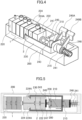
- Fig. 3 is a drawing illustrating a structure around the electrodes in the electrolyte analyzer of Example 1.
- Fig. 4 is a perspective view illustrating the structure around the electrodes in the electrolyte analyzer of Example 1 and illustrating an internal structure partially viewed through an outer wall portion.
- Fig. 5 is a drawing illustrating a state where a first electrode group is released by a first press switching unit.
- Fig. 6 includes drawings comparing a secured state with a released state of the first electrode group.
- Fig. 7 is a drawing illustrating a state where a second electrode group is released by a second press switching unit.
- Fig. 8 includes drawings comparing a secured state with a released state of the second electrode group.
- Fig. 9 is a drawing illustrating a state where the first electrode group and the second electrode group are released by the first press switching unit and the second press switching unit.
- the ISE electrode 1 forming the first electrode group including at least one electrode and the reference electrode 2 different from the ISE electrode 1 and forming the second electrode group including at least one electrode are stored in a housing 200.
- the housing 200 includes a pressing unit, the first press switching unit 210, and the second press switching unit 215.
- a first flow passage member 220, the ISE electrode 1, an intermediate flow passage member 224, the reference electrode 2, a second flow passage member 222, and the pressing unit are arranged in this order from the left side in Fig. 3 .
- the first press switching unit 210 or the second press switching unit 215 can switch between the secured state and the released state of each of the ISE electrode 1 and the reference electrode 2.
- the first press switching unit 210 is a member that switches between the secured state and the released state of the ISE electrode 1.
- the first press switching unit 210 includes a first member secured to a holding portion 245 secured to the housing 200, and a second member provided with a lever 249A and rotatably supported around a pressing shaft 243. The first member and the second member are in contact with each other via a spiral surface.
- the lever 249A of the second member When the lever 249A of the second member is rotated in the counterclockwise direction in Fig. 4 , the first member and the second member rotate along the spiral surface, and thus the total width of the first and second members in the pressing shaft 243 direction increases. On the other hand, when the lever 249A is rotated in the clockwise direction in Fig. 4 , the total width is reduced to the original length. Both of the first member and the second member have shaft holes that are axially movable with respect to the pressing shaft 243 in the axial direction.
- the lever 249A provided in the second member is a first operation lever.
- the second press switching unit 215 is a member that switches between the secured state and the released state of the reference electrode 2.
- the second press switching unit 215 includes a first member secured to a slider 230, and a second member provided with a lever 249B and rotatably supported around the pressing shaft 243.
- the lever 249B is a second operation lever.
- the lever 249B of the second member When the lever 249B of the second member is rotated in the counterclockwise direction in Fig. 4 , the first member and the second member rotate along the spiral surface, and thus the total width of the first and second members in the pressing shaft 243 direction increases. On the other hand, when the lever 249B is rotated in the clockwise direction in Fig. 4 , the total width is reduced to the original length.
- the lever 249B provided in the second member is the second operation lever. Both of the first member and the second member have the shaft holes that are axially movable with respect to the pressing shaft 243 in the axial direction. The pressing shaft 243 penetrates through the shaft holes.
- the levers 249A and 249B extend in a direction away from the pressing shaft 243 and can reduce force applied to tips of the levers when the second member is rotated along the spiral surface. In addition, since the tips of the levers are widened so that the operator can put his or her finger on them easily, the electrolyte analyzer that can be easily used can be provided.
- the first flow passage member 220 is secured to the housing 200.
- the first flow passage member 220 has a flow passage connected to the first flow passage 37 connected to the sipper nozzle 13 and the dilution tank 11 outside the housing 200.
- the ISE electrode 1 is pressed against the first flow passage member 220 by the pressing unit so as to be kept in the secured state during measurement.
- the second flow passage member 222 has a flow passage connected to the second flow passage 38 connected to the reference electrode solution bottle 5 and is not secured to the housing 200 and the like. Therefore, the second flow passage member 222 is configured to be able to move toward the first flow passage member 220 side and the first press switching unit 210 side in Fig. 3 .
- the intermediate flow passage member 224 has a groove 224A that is engaged with the slider 230, a flow passage connected to the third flow passage 39 connected to the waste liquid receptacle 35, and the pinch valve 23. Since the intermediate flow passage member 224 is not secured to the housing 200 and the like in the same manner as the second flow passage member 222, the intermediate flow passage member 224 is configured to be able to move toward the first flow passage member 220 side and the first press switching unit 210 side in Fig. 3 . A direction toward which the ISE electrode 1 or the reference electrode 2 is pressed by the intermediate flow passage member 224 is switched by the first press switching unit 210 or the second press switching unit 215.
- the slider 230 is a member that is disposed between the first press switching unit 210 and the second press switching unit 215, is driven in accordance with the switching by the first press switching unit 210 and the second press switching unit 215 so as to move the intermediate flow passage member 224 toward the first flow passage member 220 side and the first press switching unit 210 side in Fig. 3 .
- Tips of the slider 230 on the first flow passage member 220 are bent inward so as to face each other and be close to each other. Bent portions of the tips of the first flow passage member 220 can be inserted into the intermediate flow passage member 224, the intermediate flow passage member 224 has a groove 224 larger than the bent portions, and a gap is provided between the groove 224A and the slider 230 in a secured state described later.
- the first press switching unit 210 performs switching
- the slider 230 comes into contact with a side of the groove 224 in the vicinity of the reference electrode 2, and the ISE electrode 1 is switched to the released state while the reference electrode 2 is kept in a secured state.
- the second press switching unit 215 performs switching, the slider 230 comes into contact with a side of the groove 224A in the vicinity of the ISE electrode 1, and the reference electrode 2 is switched to the released state while the ISE electrode 1 is kept in the secured state.
- the pressing unit is a member that presses the ISE electrode 1 and the reference electrode 2 against one another and includes a spring 241, the pressing shaft 243, the holding portion 245, a pressing end 247, a spring bearing 248, and the like.
- the spring 241 is a member that applies force toward the first flow passage member 220 by elastic force to the spring bearing 248 secured to the pressing shaft 243 in Fig. 3 .
- a case where a coil spring is used as the spring 241 is exemplified as illustrated in Fig. 3 .
- the spring 241 is not limited to a coil spring.
- a conical spring since its length when the spring is compressed is short, there is an effect of reducing a length in the longitudinal direction of the housing) or another elastic member can be used as the spring 241.
- the pressing shaft 243 is inserted into the holding 245, the first press switching unit 210, and the second press switching unit 215 in this order.
- the pressing shaft 243 is moved in the longitudinal direction of the shaft by the switching of the first press switching unit 210 or the second press switching unit 215.
- the holding portion 245 is secured to the housing 200 and has a hole in which the pressing shaft 243 slides.
- the holding portion 245 serves as a reference surface of the first member of the first press switching unit 210.
- the holding portion 245 can receive elastic force of the spring 241.
- the pressing end 247 is secured to the pressing shaft 243 and presses the second flow passage member 222.
- Fig. 3 illustrates a state where the ISE electrode 1 and the reference electrode 2 are in a secured state, that is, in a state during measurement.
- the spring 241 is in a compressed state and is in a state of pressing the pressing end 247 via the spring bearing 248 and the pressing shaft 243. That is, the pressing unit applies pressing force to the first flow passage member 220.
- the ISE electrode 1, the intermediate flow passage member 224, the reference electrode 2, and the second flow passage member 222 are secured by being pressed against the first flow passage member 220 so as to prevent internal liquid from leaking.
- the gap is provided between the slider 230 and the groove 224A of the internal flow passage member 224, and the slider 230 does not contribute to the securing of the ISE electrode 1 and the reference electrode 2.
- a gap is provided between the second member of the first press switching unit 210, and the first member and a right surface of the slider 230 in Fig. 3 .
- the second member of the first press switching unit 210 does not contribute to the securing of the ISE electrode 1 and the reference electrode 2.
- a gap is provided between the second member of the second press switching unit 215 and a left surface of the spring bearing 248 in Fig. 3 .
- the second member of the second press switching unit 215 does not contribute to the securing of the ISE electrode 1 and the reference electrode 2.
- Figs. 5 and 6 illustrate a state where the ISE electrode 1 is in the released state and the reference electrode 2 is in the secured state.
- the width of the first press switching unit 210 is increased by switching the lever provided in the second member of the first press switching unit 210 from a state where "the ISE electrode 1 and the reference electrode 2 are in the secured state" as illustrated in Fig. 6(A) to a state where "the ISE electrode 1 is in a switched state and the reference electrode 2 is in the secured state” as illustrated in Fig. 6(B) .
- the right end surface of the second member comes into contact with the slider 230 and thus the slider 230 is moved rightward.
- the bent portion of the slider 230 on the left end side is also moved rightward and comes into contact with the right end side of the groove 224A of the intermediate flow passage member 224, and the pressing end 247 is pressed toward the second flow passage member 222, but is no longer moved toward the first flow passage member 220. Therefore, the overall pressing unit is moved toward the side opposite to the pressing end 247 side.
- the slider 230 secured to the second press switching unit 215 is also moved toward the side opposite to the first flow passage member 220, the intermediate flow passage member 224 engaged with the slider 230 via the groove 224A, and the reference electrode 2 and the second flow passage member 222 located between the intermediate flow passage member 224 and the pressing end 247 are moved in the same direction. Therefore, the ISE electrode 1 is switched from the secured state to the released state.
- the spring 241 applies force to the pressing end 247 so as to press the reference electrode 2 and the second flow passage member 222, the reference electrode 2 is kept sandwiched between the intermediate flow passage member 224 and the second flow passage member 222 by the pressing end 247. That is, even when the ISE electrode 1 is switched from the secured state to the released state, the reference electrode 2 is kept in the secured state.
- Figs. 7 and 8 illustrate a state where the ISE electrode 1 is in the secured state, but the reference electrode 2 is in the released state.
- the width of the second press switching unit 215 is increased by switching the lever provided in the second member of the second press switching unit 215 from a state where "the ISE electrode 1 and the reference electrode 2 are in the secured state" as illustrated in Fig. 8(A) to a state where "the ISE electrode 1 is in the secured state and the reference electrode 2 is in a switched state" as illustrated in Fig. 8(B) .
- the slider 230 secured to the second press switching unit 215 is also pressed toward the first flow passage member 220, and is moved toward the first flow passage member 220 until the slider 230 interferes with the groove 224A of the intermediate flow passage member 224. After the interference, the slider 230 cannot move toward the first flow passage member 220. Therefore, the overall pressing unit is moved toward the side opposite to intermediate flow passage member 224, and the reference electrode 2 is switched from the secured state to the released state.
- the slider 230 interferes with the groove 224A of the intermediate flow passage member 224, and the intermediate flow passage member 224 presses the ISE electrode 1 toward the first flow passage member 220. Therefore, the ISE electrode 1 is kept in the secured state.
- Fig. 9 illustrates a state where both of the ISE electrode 1 and the reference electrode 2 are in the released state.
- the ISE electrode 1 is switched from the secured state to the released state as illustrated in Figs. 5 and 6 described above
- the reference electrode 2 is switched from the secured state to the released state as illustrated in Figs. 7 and 8 .
- the electrodes are switched from the secured state to the released state in reverse order.
- the above-described electrolyte analyzer 100 of Example 1 of the present invention includes the ISE electrode 1 including at least one electrode, the reference electrode 2 different from the ISE electrode 1 and including at least one electrode, and the housing 200 housing the electrodes of the ISE electrode 1 and the reference electrode 2.
- the housing 200 includes the pressing unit that presses the electrodes against one another, the first press switching unit 210 that switches between the secured state and the released state of the ISE electrode 1, and the second press switching unit 215 that switches between the secured state and the released state of the reference electrode 2.
- the housing 200 can switch between the secured state and the released state of each of the ISE electrode 1 and the reference electrode 2.
- the ISE electrode 1 and the reference electrode 2 can be released simultaneously, all the electrodes can be detached. Therefore, it is easy to clean the overall inside of the housing 200, and it is possible to the electrolyte analyzer that can be easily cleaned and easily used.
- the arrangement of the electrodes is the same as the arrangement of the corresponding levers such that the ISE electrode 1 is arranged on the left side, the reference electrode 2 is arranged on the right side, the lever 249A that is operated to attach and detach the ISE electrode 1 is arranged on the left side, and the lever 249B that is operated to attach and detach the reference electrode 2 is arranged on the right side, it is possible to reduce operation errors and provide the electrolyte analyzer with excellent operability.
- Fig. 10 is a drawing illustrating a structure around electrodes in the electrolyte analyzer of Example 2.
- Fig. 11 is a drawing illustrating a state where a first electrode group is released by a first press switching unit.
- Fig. 12 is a drawing illustrating a state where a second electrode group is released by a second press switching unit.
- a pressing unit includes a spring 341, a pressing shaft 343, a holding portion 345, pressing ends 347 and 348, and the like in an analysis chamber 50 of the electrolyte analyzer 100 of the present Example as illustrated in Fig. 10 .
- the spring 341 is disposed between the holding portion 345 and the pressing end 347, the pressing end 347 forms one end on a second flow passage member 322 side, and the pressing end 348 forms the other end.
- a housing 300, a first press switching unit 310, a second press switching unit 315, a first flow passage member 320, a second flow passage member 322, an intermediate flow passage member 324, a groove 324A thereof, the pressing shaft 343, and the holding portion 345 have substantially the same configurations as those of the housing 200, the first press switching unit 210, the second press switching unit 215, the first flow passage member 220, the second flow passage member 222, the intermediate flow passage member 224, the groove 224A thereof, the pressing shaft 243, and the holding portion 245 of Example 1.
- the width of the first press switching unit 310 is increased by switching a lever of a second member of the first press switching unit 310.
- a right end surface of the second member comes into contact with the slider 330 so as to move the slider 330 rightward, and a bent portion of a left end side of the slider 330 is also moved rightward to come into contact with a right end side of the groove 324A of the intermediate flow passage member 324.
- the pressing end 347 is also pressed toward the second flow passage member 322, but is no longer moved, and thus the overall pressing unit is moved toward the side opposite to the second flow passage member 322.
- the slider 330 is also moved toward the side opposite to the second flow passage member 322, the intermediate flow passage member 324 engaged with the slider 330 via the groove 324A, the reference electrode 2, and the second flow passage member 322 are moved together with the slider 330 in the same direction. Therefore, the ISE electrode 1 is switched from a secured state to a released state.
- the reference electrode 2 since the spring 341 applies force toward the second flow passage member 322 side to the pressing unit, the reference electrode 2 remains pressed against the intermediate flow passage member 324 by the pressing end 347 of the pressing unit, and thus the reference electrode 2 is kept in the secured state even when the ISE electrode 1 is switched to the released state.
- the width of the second press switching unit 315 is increased by switching the second member of the second press switching unit 315 by the lever.
- the slider 330 secured to the second press switching unit 315 is pressed toward the first flow passage member 320, and is moved toward the first flow passage member 320 until the groove 324A of the intermediate flow passage member 324 interferes.
- the overall pressing unit is moved toward the side opposite to the intermediate flow passage member 324 side, and the reference electrode 2 is switched from the secured state to the released state.
- the slider 330 interferes with the groove 324 of the intermediate flow passage member 324, and the intermediate flow passage member 324 presses the ISE electrode 1 toward the first flow passage member 320 side. Therefore, the ISE electrode 1 is kept in the secured state.
- Fig. 13 is a drawing illustrating a structure around electrodes in an electrolyte analyzer of Example 3.
- an ISE electrode 1 and a reference electrode 2 are housed in the same manner, but a configuration of a pressing unit is different from Examples 1 and 2.
- the pressing unit in the housing 400 of the present Example includes a first pressing unit in which a first press switching unit 410 is inserted and a second pressing unit in which a second press switching unit 415 is inserted.
- An intermediate flow passage member 424 is secured to the housing 400.
- the first pressing unit includes a pressing shaft 443A in which the first press switching unit 410 is inserted, pressing ends 447A and 448A secured to the pressing shaft 443A, and the like, which are not secured to the housing 400, except for a holding portion 445A.
- a spring 441A that applies force in a predetermined direction is stretched between the pressing end 447A and the holding portion 445A.
- the second pressing unit includes a pressing shaft 443B in which the second press switching unit 415 is inserted, pressing ends 447B and 448B secured to the pressing shaft 443B, and the like, which are not secured to the housing 400, except for a holding portion 445B.
- a spring 441B that applies force in a predetermined direction is stretched between the pressing end 447B and the holding portion 445B.
- the ISE electrode 1 and a first flow passage member 420 are pressed by the spring 441A via the pressing end 447A against the intermediate flow passage member 424 secured to the housing 400, and thus the ISE electrode 1 is kept in the secured state.
- the reference electrode 2 and a second flow passage member 422 are pressed by a spring 441B via the pressing end 447B against the intermediate flow passage member 424, and thus the reference electrode 2 is kept in the secured state.
- the width of the first press switching unit 410 is increased by switching a lever of a second member of the first press switching unit 410, and the pressing end 448A is moved leftward in the drawing, that is, in a direction away from the holding portion 445A. Therefore, the pressing end 447A is separated from the first flow passage member 420, pressing force of the ISE electrode 1 toward the intermediate flow passage member 424 is eliminated, and the ISE electrode 1 is switched to the released state. In this case, the state of the reference electrode 2 side is not changed and thus the reference electrode 2 is kept in the secured state.
- the width of the second press switching unit 415 is increased by switching a lever of a second member of the second press switching unit 415, and the pressing end 448B is moved rightward in the drawing, that is, in a direction away from the holding portion 445B. Therefore, the pressing end 447B is separated from the second flow passage member 422, pressing force of the reference electrode 2 toward the intermediate flow passage member 424 is eliminated, and the reference electrode 2 is switched to the released state. In this case, the state of the ISE electrode 1 side is not changed and thus the ISE electrode 1 is kept in the secured state.
- the pressing unit in Example 3 of the present invention includes the first pressing unit in which the first press switching unit 410 is inserted and the second pressing unit in which the second press switching unit 415 is inserted, effects that are substantially the same as those of the electrolyte analyzer of Example 1 described above can be obtained.
- Example 3 the first lever that is operated to attach and detach the ISE electrode 1, and the second lever that is operated to attach and detach the reference electrode 2 are arranged on opposite sides with the housing 300 interposed therebetween. Since the first lever is arranged adjacent to the ISE electrode 1, and the second lever is arranged adjacent to the reference electrode 2, the levers are adjacent to the electrodes to be attached or detached, it is easy to understand the correspondence between the electrode to be attached or detached and the lever to be operated, and it is possible to provide the electrolyte analyzer that can be easily used.
- part of the configuration of one example can be replaced with the configurations of other examples, and in addition, the configuration of the one example can also be added with the configurations of other examples.
- part of the configuration of each of the examples can be subjected to addition, deletion, and replacement with respect to other configurations.
Landscapes
- Chemical & Material Sciences (AREA)
- Life Sciences & Earth Sciences (AREA)
- Health & Medical Sciences (AREA)
- Physics & Mathematics (AREA)
- Chemical Kinetics & Catalysis (AREA)
- Electrochemistry (AREA)
- Molecular Biology (AREA)
- Analytical Chemistry (AREA)
- Biochemistry (AREA)
- General Health & Medical Sciences (AREA)
- General Physics & Mathematics (AREA)
- Immunology (AREA)
- Pathology (AREA)
- Automatic Analysis And Handling Materials Therefor (AREA)
Abstract
Description
- The present invention relates to an electrolyte analyzer.
- As an example of an electrolyte analyzer that prevents contamination from being caused by different reagents coming into contact with an aspiration nozzle in work of replacing a reagent by a user,
Patent Literature 1 describes that an electrolyte analyzer includes a nozzle support portion that is coupled to aspiration nozzles and is movable between a reagent container replacement position and a reagent aspiration position, a locking mechanism that is fitted to the nozzle support portion moved to the reagent container replacement position so as to fix the nozzle support portion at the reagent container replacement position, and an unlocking mechanism that can release the fitting of the locking mechanism to the nozzle support portion in a state in which power is supplied, and that, when a reagent container satisfies a predetermined condition, the unlocking mechanism is controlled to release the fitting of the locking mechanism to the nozzle support portion so as to cause the nozzle support portion to move to the reagent aspiration position. - Patent Literature 1: International Publication No.
2019/198400 - The electrolyte analyzer described above in
Patent Literature 1 is a device configured to measure the concentrations of specific electrolytes (sodium (Na), potassium (K), chlorine (Cl), and the like) contained in electrolyte solutions such as human blood and urine and measures the concentrations using an ion selective electrode. - In a general method for measuring the concentration of an electrolyte, first, serum as an electrolyte solution is directly supplied to an ion selective electrode or a sample solution diluted with a dilute solution is supplied to the ion selective electrode, and a potential between the supplied solution and a reference electrode solution is measured. Next, or before the above-described measurement, a flow type is mainly used to perform a procedure for supplying a standard solution to the ion selective electrode, measuring a potential between the supplied standard solution and the reference electrode solution in the same manner, and calculating the concentration of an electrolyte in the sample solution from the potential level between the two solutions.
- In such a flow-type electrolyte analyzer, not only the reagents such as the dilute solution, the standard solution, and the reference electrode solution but also the ion selective electrode are used as consumables, and work of replacing the consumables is performed by a user.
- As the ion selective electrode, two types of electrodes, measurement electrodes (hereinafter, referred to as ISE electrodes (ion selective electrodes) in some cases) for Na, K, and Cl according to measurement items, and a reference electrode, are used. In general, expiration dates of the ISE electrodes may be significantly different from an expiration date of the reference electrode, and the number of times that measurement can be performed with each of the ISE electrodes may be significantly different from the number of times that measurement can be performed with the reference electrode.
- Each of the ISE electrodes and the reference electrode includes a flow passage having an electrode membrane. The ISE electrodes and the reference electrode are used in close contact with each other in, for example, an O-ring such that a liquid does not leak.
- In a case where a user replaces each of the ISE electrodes and the reference electrode, each of the electrodes can be detached and attached by temporarily releasing contact portions between the electrodes.
- Meanwhile, as described above, since the timing of replacing each of the electrodes may be different from the timing of replacing the other electrodes, even when an electrode is not replaced, it is inevitable that an internal liquid will leak due to temporal release of close contact. In this case, since it is necessary to take measures such as cleaning the electrodes that have been replaced and the electrode that is not replaced, there was a need to reduce the burden of cleaning on the user.
- The present invention provides an electrolyte analyzer capable of reducing a burden on a user during replacement work, as compared with conventional techniques.
- The present invention includes a plurality of means for solving the above-described problems, an example of the means includes a first electrode group that includes at least one electrode, a second electrode group that is different from the first electrode group and includes at least one electrode, and an electrode housing that houses the electrodes of the first electrode group and the second electrode group, the electrode housing includes a pressing unit that presses the electrodes against one another, a first switching unit that switches between a secured state and a released state of the first electrode group, and a second switching unit that switches between a secured state and a released state of the second electrode group, and each of the first electrode group and the second electrode group can be switched between the secured state and the released state.
- According to the present invention, it is possible to reduce a burden on a user during replacement work as compared with conventional techniques. Problems, configurations and effects other than those described above will be clarified by the following description of Examples.
-
-
Fig. 1 is a drawing illustrating an overall configuration of an electrolyte analyzer of Example 1 of the present invention. -
Fig. 2 is a drawing illustrating a schematic configuration of an analysis chamber in the electrolyte analyzer of Example 1. -
Fig. 3 is a drawing illustrating a structure around electrodes in the electrolyte analyzer of Example 1 and illustrating a state where both a first electrode group and a second electrode group are secured. -
Fig. 4 is a partial transparent perspective view illustrating the structure around electrodes in the electrolyte analyzer of Example 1. -
Fig. 5 is a drawing illustrating a state where the first electrode group is released by a first press switching unit in the electrolyte analyzer of Example 1. -
Fig. 6 includes drawings comparing a secured state with a released state of the first electrode group in the electrolyte analyzer of Example 1. -
Fig. 7 is a drawing illustrating a state where the second electrode group is released by a second press switching unit in the electrolyte analyzer of Example 1. -
Fig. 8 includes drawings comparing a secured state with a released state of the second electrode group in the electrolyte analyzer of Example 1. -
Fig. 9 is a drawing illustrating a state where the first electrode group and the second electrode group are released by the first press switching unit and the second press switching unit in the electrolyte analyzer of Example 1. -
Fig. 10 is a drawing illustrating a structure around electrodes in an electrolyte analyzer of Example 2 of the present invention. -
Fig. 11 is a drawing illustrating a state where a first electrode group is released by a first press switching unit in the electrolyte analyzer of Example 2. -
Fig. 12 is a drawing illustrating a state where a second electrode group is released by a second press switching unit in the electrolyte analyzer of Example 2. -
Fig. 13 is a drawing illustrating a structure around electrodes in an electrolyte analyzer of Example 3 of the present invention. - Hereinafter, Examples of an electrolyte analyzer of the present invention are described with reference to the accompanying drawings. In the drawings used in the present specification, the same or corresponding components are denoted by the same or similar reference signs, and repeated descriptions of these components may be omitted.
- Example 1 of the electrolyte analyzer of the present invention is described with reference to
Figs. 1 to 9 . - First, an overall configuration of an electrolyte analyzer and a configuration of a main section of the electrolyte analyzer are described with reference to
Figs. 1 and2 .Fig. 1 is a drawing illustrating the overall configuration of the electrolyte analyzer of Example 1, andFig. 2 is a drawing illustrating a schematic configuration of an analysis chamber in the electrolyte analyzer. - The
electrolyte analyzer 100 illustrated inFig. 1 includes aconveyance line 71, agripper 55,dispensing lines pre-analysis buffer 61, apost-analysis buffer 62, twoanalysis chambers 50, asample probe 14, adisplay unit 80, acontrol unit 29, and the like. - The
conveyance line 71 is a device disposed at an end portion of the analyzer and configured to convey aconveying container 90, which has loaded thereon a plurality ofsample containers 15 storing a sample injected from a sample injector (not illustrated), to a conveyance position by thegripper 55, and to unload theconveying container 90 for which measurement has been completed. - In the present Example, an example in which the plurality of
sample containers 15 are loaded on theconveying container 90 is described. However, one ormore sample containers 15 may be loaded on theconveying container 90. Another example of theconveying container 90 is a sample holder capable of holding onesample container 15, or the like. - The
gripper 55 is a mechanism for conveying theconveying container 90 from theconveyance line 71 to the dispensinglines dispensing lines conveyance line 71. - The
dispensing lines sample containers 15 targeted for dispensing and loaded on thetransport container 90 to a dispensing position by thesample probe 14, or for conveying theconveying container 90 having loaded thereon thesample containers 15 after dispensing to thepost-analysis buffer 62. - The
pre-analysis buffer 61 and thepost-analysis buffer 62 are spaces in which asample container 15 for which dispensing to theanalysis chamber 50 is to be performed and asample container 15 after completion of an analysis operation stand by until being conveyed to another location. - The
analysis chamber 50 is an analyzer having anISE electrode 1 that measures the concentration of an electrolyte of a sample. Details thereof are described with reference toFig. 2 . The number ofanalysis chambers 50 disposed in theelectrolyte analyzer 100 is not limited to one and can be two or more. - The
analysis chamber 50 illustrated inFig. 2 is a flow-type analysis chamber using an ion selective electrode. -
Fig. 2 illustrates five mechanisms, which are a sample dispensing section, an electrode section, a reagent section, a mechanism section, and a waste liquid mechanism as main mechanisms of theanalysis chamber 50, and acontrol unit 29 that controls these mechanisms, calculates the concentration of an electrolyte based on a measurement result, and performs display control. - The sample dispensing section includes the
sample probe 14. A sample such as a patient sample held in asample container 15 is dispensed and drawn into the analyzer by thesample probe 14. The sample is a general term for an analysis target collected from a patient's body, and is, for example, blood, urine, or the like. An object to be analyzed that has undergone a predetermined pretreatment is also called a sample. - The electrode section includes a
dilution tank 11, asipper nozzle 13, adilute solution nozzle 24, an internalstandard solution nozzle 25, theISE electrode 1, areference electrode 2, apinch valve 23, avoltmeter 27, and anamplifier 28. The sample dispensed by the sample dispensing section is ejected into thedilution tank 11 and diluted and stirred with a dilute solution ejected from thedilute solution nozzle 24 into thedilution tank 11. - The
sipper nozzle 13 is connected to theISE electrode 1 via afirst flow passage 37. The diluted sample solution aspirated from thedilution tank 11 is sent to theISE electrode 1 through thefirst flow passage 37. - Meanwhile, a reference electrode solution stored in a reference
electrode solution bottle 5 is sent to thereference electrode 2 through asecond flow passage 38 by operating asipper syringe 10 in a state in which thepinch valve 23 is closed. The diluted sample solution sent to an ISE electrode flow passage and the reference electrode solution sent to the reference electrode flow passage come into contact with each other, whereby theISE electrode 1 and thereference electrode 2 become electrically conductive with each other. The electrode section measures the concentration of a specific electrolyte contained in the sample based on a potential difference between theISE electrode 1 and thereference electrode 2. - Specifically, an ion sensitive membrane with a property that electromotive force changes according to the concentrations of specific ions (for example, a sodium ion (Na+), a potassium ion (K+), a chlorine ion (Cl-), and the like) contained in the sample solution is attached to the
ISE electrode 1. TheISE electrode 1 outputs electromotive force according to each of the ion concentrations in the sample solution, and thevoltmeter 27 and theamplifier 28 acquire electromotive force between theISE electrode 1 and thereference electrode 2. Thecontrol unit 29 calculates each of the ion concentrations in the sample from the acquired electromotive force and displays the calculated ion concentrations. The sample solution remaining in thedilution tank 11 is discharged by the waste liquid mechanism. - The potential difference between the
ISE electrode 1 and thereference electrode 2 is easily affected by an effect such as a change in temperature. To correct a variation in the potential caused by the effect such as a change in temperature, in a time period after the measurement of one sample and before the measurement of the next sample, the internal standard solution is ejected from the internalstandard solution nozzle 25 into thedilution tank 11, and measurement is performed in the same manner as in the case of the sample described above. It is preferable to perform the correction according to the amount of variation using the result of the internal standard solution measurement performed between the sample measurements. In this case, the dilution of the internal standard solution is not performed. - The reagent section includes an
aspiration nozzle 6 for aspirating a reagent from a reagent container, adegassing mechanism 7, and afilter 16 and supplies a reagent necessary for measurement. In a case where electrolyte measurement is performed, three types of reagents, which are the internal standard solution, the dilute solution, and the reference electrode solution, are used as reagents, and an internalstandard solution bottle 3 storing the internal standard solution, adilute solution bottle 4 storing the dilute solution, and the referenceelectrode solution bottle 5 storing the reference electrode solution are set in the reagent section.Fig. 2 illustrates this state. In a case where the analyzer is cleaned, a cleaning liquid bottle storing a cleaning liquid is set in the reagent section. - The internal
standard solution bottle 3 and thedilute solution bottle 4 are connected to the internalstandard solution nozzle 25 and thedilute solution nozzle 24 via thefilter 16 and flow passages, respectively, and the nozzles are disposed such that tips of the nozzles are introduced in thedilution tank 11. The referenceelectrode solution bottle 5 is connected to thereference electrode 2 via thefilter 16 and a flow passage. - The
degassing mechanism 7 is connected to the flow passage between thedilute solution bottle 4 and thedilution tank 11 and to the flow passage between the referenceelectrode solution bottle 5 and thereference electrode 2, and a degassed reagent is supplied into thedilution tank 11 and thereference electrode 2. Since the reagent is aspirated upward from the bottle by setting the flow passages to negative pressure by a syringe, gas dissolved in the reagent appears as bubbles in the reagent. The degassing mechanism is provided to prevent the reagent with bubbles from being supplied into thedilution tank 11 and thereference electrode 2. - The mechanism section includes an internal
standard solution syringe 8, adilute solution syringe 9, thesipper syringe 10,solenoid valves dilution tank 11 by operations of the internalstandard solution syringe 8, thedilute solution syringe 9, and the solenoid valves disposed in flow passages. The preheating 12 controls the temperatures of the internal standard solution and the dilute solution to be sent to theISE electrode 1 to a certain range so as to suppress an effect of the temperatures on theISE electrode 1. - The waste liquid mechanism includes a first
waste liquid nozzle 26, a secondwaste liquid nozzle 36, avacuum bin 34, awaste liquid receptacle 35, avacuum pump 33, andsolenoid valves dilution tank 11 and a reaction solution remaining in the flow passages of the electrode section through athird flow passage 39. - Returning to
Fig. 1 , thedisplay unit 80 includes a liquid crystal display or the like on which various screens such as an operation screen for ordering a measurement item for measurement on a sample to be measured, and a screen for checking a result of the measurement are displayed. - A printer or the like may be provided instead of the liquid crystal display. Alternatively, a display and a printer may be provided, or a touch panel display for setting various parameters based on an operation screen displayed, and entering a measurement result, request information of measurement, instructions to start and stop analysis, and the like may be provided.
- The
control unit 29 is connected to theanalysis chamber 50 and the like via a wired or wireless network line and controls operations in theelectrolyte analyzer 100 including theanalysis chamber 50. In addition, thecontrol unit 29 performs calculation using the potential of theISE electrode 1 for which the sample solution was measured, and calculates the concentrations of the electrolytes in the sample. In this case, the concentrations of the electrolytes are more accurately measured by performing calibration based on the potential of the ISE electrode for which the internal standard solution was measured. - The
control unit 29 can be a computer including a central processing unit (CPU), a random access memory (RAM), a storage unit, and an I/O port. The RAM, the storage unit, and the I/O port are configured to exchange data with the CPU via an internal bus. The I/O port is connected to the mechanisms described above and controls the operations of the mechanisms. The operation control is performed by reading a program stored in the storage unit and executing the read program by the CPU. In addition, an input/output unit is connected to thecontrol unit 29 such that input from a user and a measurement result can be displayed. - Next, an operation of measuring the concentration of an electrolyte by an electrolyte measuring device illustrated in
Fig. 2 is described. The measurement operation is controlled by thecontrol unit 29. - First, a sample dispensed from a
sample container 15 by thesample probe 14 of the sample dispensing section is ejected into thedilution tank 11 of the electrode section. After the sample is dispensed into thedilution tank 11, the dilute solution is ejected from thedilute solution bottle 4 by the operation of thedilute solution syringe 9 to dilute the sample. As described above, to prevent bubbles from being formed due to a change in temperature of the dilute solution in the flow passage or due to pressure applied to the dilute solution in the flow passage, a degassing treatment is performed by thedegassing mechanism 7 attached in the middle of a dilute solution flow passage. The diluted sample solution is aspirated to theISE electrode 1 by the operation of thesipper syringe 10 and the operation of thesolenoid valve 22. - Meanwhile, the reference electrode solution is sent from the reference
electrode solution bottle 5 into thereference electrode 2 by thepinch valve 23 and thesipper syringe 10. The reference electrode solution is, for example, an aqueous solution containing potassium chloride (KCl) at a predetermined concentration. When the sample solution comes into contact with the reference electrode solution, theISE electrode 1 and thereference electrode 2 become electrically conductive with each other. It is desirable that the concentration of an electrolyte in the reference electrode solution be high in order to suppress an effect of a variation in the concentration during the sending of the sample. However, since the reference electrode solution may crystallize and cause clogging of the flow passage when the concentration is close to the saturated concentration, it is desirable that the concentration be in a range of 0.5 mmol/L to 3.0 mmol/L. The potential of the ISE electrode with respect to the potential of the reference electrode as a reference is measured using thevoltmeter 27 and theamplifier 28. - In addition, the internal standard solution in the internal
standard solution bottle 3 set in the reagent section before and after the sample measurement is ejected into thedilution tank 11 by the internalstandard solution syringe 8, and the concentration of an electrolyte in the internal standard solution is measured in the same manner as the sample measurement. - Next, the structure of the
analysis chamber 50 of the present invention is described in detail with reference toFigs. 3 to 9 .Fig. 3 is a drawing illustrating a structure around the electrodes in the electrolyte analyzer of Example 1.Fig. 4 is a perspective view illustrating the structure around the electrodes in the electrolyte analyzer of Example 1 and illustrating an internal structure partially viewed through an outer wall portion.Fig. 5 is a drawing illustrating a state where a first electrode group is released by a first press switching unit.Fig. 6 includes drawings comparing a secured state with a released state of the first electrode group.Fig. 7 is a drawing illustrating a state where a second electrode group is released by a second press switching unit.Fig. 8 includes drawings comparing a secured state with a released state of the second electrode group.Fig. 9 is a drawing illustrating a state where the first electrode group and the second electrode group are released by the first press switching unit and the second press switching unit. - In the
electrolyte analyzer 100 of the present Example, as illustrated inFig. 3 , theISE electrode 1 forming the first electrode group including at least one electrode and thereference electrode 2 different from theISE electrode 1 and forming the second electrode group including at least one electrode are stored in ahousing 200. - As illustrated in
Fig. 3 , thehousing 200 includes a pressing unit, the firstpress switching unit 210, and the secondpress switching unit 215. In thehousing 200, a firstflow passage member 220, theISE electrode 1, an intermediateflow passage member 224, thereference electrode 2, a secondflow passage member 222, and the pressing unit are arranged in this order from the left side inFig. 3 . - Among them, the first
press switching unit 210 or the secondpress switching unit 215 can switch between the secured state and the released state of each of theISE electrode 1 and thereference electrode 2. - The first
press switching unit 210 is a member that switches between the secured state and the released state of theISE electrode 1. The firstpress switching unit 210 includes a first member secured to a holdingportion 245 secured to thehousing 200, and a second member provided with alever 249A and rotatably supported around apressing shaft 243. The first member and the second member are in contact with each other via a spiral surface. - When the
lever 249A of the second member is rotated in the counterclockwise direction inFig. 4 , the first member and the second member rotate along the spiral surface, and thus the total width of the first and second members in thepressing shaft 243 direction increases. On the other hand, when thelever 249A is rotated in the clockwise direction inFig. 4 , the total width is reduced to the original length. Both of the first member and the second member have shaft holes that are axially movable with respect to thepressing shaft 243 in the axial direction. Thelever 249A provided in the second member is a first operation lever. - The second
press switching unit 215 is a member that switches between the secured state and the released state of thereference electrode 2. The secondpress switching unit 215 includes a first member secured to aslider 230, and a second member provided with alever 249B and rotatably supported around thepressing shaft 243. Thelever 249B is a second operation lever. - When the
lever 249B of the second member is rotated in the counterclockwise direction inFig. 4 , the first member and the second member rotate along the spiral surface, and thus the total width of the first and second members in thepressing shaft 243 direction increases. On the other hand, when thelever 249B is rotated in the clockwise direction inFig. 4 , the total width is reduced to the original length. Thelever 249B provided in the second member is the second operation lever. Both of the first member and the second member have the shaft holes that are axially movable with respect to thepressing shaft 243 in the axial direction. Thepressing shaft 243 penetrates through the shaft holes. - The
levers pressing shaft 243 and can reduce force applied to tips of the levers when the second member is rotated along the spiral surface. In addition, since the tips of the levers are widened so that the operator can put his or her finger on them easily, the electrolyte analyzer that can be easily used can be provided. - The first
flow passage member 220 is secured to thehousing 200. The firstflow passage member 220 has a flow passage connected to thefirst flow passage 37 connected to thesipper nozzle 13 and thedilution tank 11 outside thehousing 200. TheISE electrode 1 is pressed against the firstflow passage member 220 by the pressing unit so as to be kept in the secured state during measurement. - The second
flow passage member 222 has a flow passage connected to thesecond flow passage 38 connected to the referenceelectrode solution bottle 5 and is not secured to thehousing 200 and the like. Therefore, the secondflow passage member 222 is configured to be able to move toward the firstflow passage member 220 side and the firstpress switching unit 210 side inFig. 3 . - The intermediate
flow passage member 224 has agroove 224A that is engaged with theslider 230, a flow passage connected to thethird flow passage 39 connected to thewaste liquid receptacle 35, and thepinch valve 23. Since the intermediateflow passage member 224 is not secured to thehousing 200 and the like in the same manner as the secondflow passage member 222, the intermediateflow passage member 224 is configured to be able to move toward the firstflow passage member 220 side and the firstpress switching unit 210 side inFig. 3 . A direction toward which theISE electrode 1 or thereference electrode 2 is pressed by the intermediateflow passage member 224 is switched by the firstpress switching unit 210 or the secondpress switching unit 215. - The
slider 230 is a member that is disposed between the firstpress switching unit 210 and the secondpress switching unit 215, is driven in accordance with the switching by the firstpress switching unit 210 and the secondpress switching unit 215 so as to move the intermediateflow passage member 224 toward the firstflow passage member 220 side and the firstpress switching unit 210 side inFig. 3 . - Tips of the
slider 230 on the firstflow passage member 220, that is, on the left side inFig. 3 are bent inward so as to face each other and be close to each other. Bent portions of the tips of the firstflow passage member 220 can be inserted into the intermediateflow passage member 224, the intermediateflow passage member 224 has agroove 224 larger than the bent portions, and a gap is provided between thegroove 224A and theslider 230 in a secured state described later. Meanwhile, when the firstpress switching unit 210 performs switching, theslider 230 comes into contact with a side of thegroove 224 in the vicinity of thereference electrode 2, and theISE electrode 1 is switched to the released state while thereference electrode 2 is kept in a secured state. When the secondpress switching unit 215 performs switching, theslider 230 comes into contact with a side of thegroove 224A in the vicinity of theISE electrode 1, and thereference electrode 2 is switched to the released state while theISE electrode 1 is kept in the secured state. - The pressing unit is a member that presses the
ISE electrode 1 and thereference electrode 2 against one another and includes aspring 241, thepressing shaft 243, the holdingportion 245, apressing end 247, aspring bearing 248, and the like. - The
spring 241 is a member that applies force toward the firstflow passage member 220 by elastic force to thespring bearing 248 secured to thepressing shaft 243 inFig. 3 . A case where a coil spring is used as thespring 241 is exemplified as illustrated inFig. 3 . However, thespring 241 is not limited to a coil spring. A conical spring (since its length when the spring is compressed is short, there is an effect of reducing a length in the longitudinal direction of the housing) or another elastic member can be used as thespring 241. - The
pressing shaft 243 is inserted into the holding 245, the firstpress switching unit 210, and the secondpress switching unit 215 in this order. Thepressing shaft 243 is moved in the longitudinal direction of the shaft by the switching of the firstpress switching unit 210 or the secondpress switching unit 215. - The holding
portion 245 is secured to thehousing 200 and has a hole in which thepressing shaft 243 slides. The holdingportion 245 serves as a reference surface of the first member of the firstpress switching unit 210. In addition, the holdingportion 245 can receive elastic force of thespring 241. - The
pressing end 247 is secured to thepressing shaft 243 and presses the secondflow passage member 222. -
Fig. 3 illustrates a state where theISE electrode 1 and thereference electrode 2 are in a secured state, that is, in a state during measurement. When theISE electrode 1 and thereference electrode 2 are housed, thespring 241 is in a compressed state and is in a state of pressing thepressing end 247 via thespring bearing 248 and thepressing shaft 243. That is, the pressing unit applies pressing force to the firstflow passage member 220. TheISE electrode 1, the intermediateflow passage member 224, thereference electrode 2, and the secondflow passage member 222 are secured by being pressed against the firstflow passage member 220 so as to prevent internal liquid from leaking. - The gap is provided between the
slider 230 and thegroove 224A of the internalflow passage member 224, and theslider 230 does not contribute to the securing of theISE electrode 1 and thereference electrode 2. - In addition, a gap is provided between the second member of the first
press switching unit 210, and the first member and a right surface of theslider 230 inFig. 3 . The second member of the firstpress switching unit 210 does not contribute to the securing of theISE electrode 1 and thereference electrode 2. Furthermore, a gap is provided between the second member of the secondpress switching unit 215 and a left surface of thespring bearing 248 inFig. 3 . The second member of the secondpress switching unit 215 does not contribute to the securing of theISE electrode 1 and thereference electrode 2. -
Figs. 5 and6 illustrate a state where theISE electrode 1 is in the released state and thereference electrode 2 is in the secured state. The width of the firstpress switching unit 210 is increased by switching the lever provided in the second member of the firstpress switching unit 210 from a state where "theISE electrode 1 and thereference electrode 2 are in the secured state" as illustrated inFig. 6(A) to a state where "theISE electrode 1 is in a switched state and thereference electrode 2 is in the secured state" as illustrated inFig. 6(B) . - When the width of the first
press switching unit 210 increases, the right end surface of the second member comes into contact with theslider 230 and thus theslider 230 is moved rightward. The bent portion of theslider 230 on the left end side is also moved rightward and comes into contact with the right end side of thegroove 224A of the intermediateflow passage member 224, and thepressing end 247 is pressed toward the secondflow passage member 222, but is no longer moved toward the firstflow passage member 220. Therefore, the overall pressing unit is moved toward the side opposite to thepressing end 247 side. In this case, since theslider 230 secured to the secondpress switching unit 215 is also moved toward the side opposite to the firstflow passage member 220, the intermediateflow passage member 224 engaged with theslider 230 via thegroove 224A, and thereference electrode 2 and the secondflow passage member 222 located between the intermediateflow passage member 224 and thepressing end 247 are moved in the same direction. Therefore, theISE electrode 1 is switched from the secured state to the released state. - In this case, since the
spring 241 applies force to thepressing end 247 so as to press thereference electrode 2 and the secondflow passage member 222, thereference electrode 2 is kept sandwiched between the intermediateflow passage member 224 and the secondflow passage member 222 by thepressing end 247. That is, even when theISE electrode 1 is switched from the secured state to the released state, thereference electrode 2 is kept in the secured state. -
Figs. 7 and8 illustrate a state where theISE electrode 1 is in the secured state, but thereference electrode 2 is in the released state. The width of the secondpress switching unit 215 is increased by switching the lever provided in the second member of the secondpress switching unit 215 from a state where "theISE electrode 1 and thereference electrode 2 are in the secured state" as illustrated inFig. 8(A) to a state where "theISE electrode 1 is in the secured state and thereference electrode 2 is in a switched state" as illustrated inFig. 8(B) . - When the width of the second
press switching unit 215 is increased, theslider 230 secured to the secondpress switching unit 215 is also pressed toward the firstflow passage member 220, and is moved toward the firstflow passage member 220 until theslider 230 interferes with thegroove 224A of the intermediateflow passage member 224. After the interference, theslider 230 cannot move toward the firstflow passage member 220. Therefore, the overall pressing unit is moved toward the side opposite to intermediateflow passage member 224, and thereference electrode 2 is switched from the secured state to the released state. - In this case, since the
spring 241 applies force toward the intermediateflow passage member 224 to theslider 230, theslider 230 interferes with thegroove 224A of the intermediateflow passage member 224, and the intermediateflow passage member 224 presses theISE electrode 1 toward the firstflow passage member 220. Therefore, theISE electrode 1 is kept in the secured state. -
Fig. 9 illustrates a state where both of theISE electrode 1 and thereference electrode 2 are in the released state. After theISE electrode 1 is switched from the secured state to the released state as illustrated inFigs. 5 and6 described above, thereference electrode 2 is switched from the secured state to the released state as illustrated inFigs. 7 and8 . Alternatively, the electrodes are switched from the secured state to the released state in reverse order. - Next, effects of the present Example are described.
- The above-described
electrolyte analyzer 100 of Example 1 of the present invention includes theISE electrode 1 including at least one electrode, thereference electrode 2 different from theISE electrode 1 and including at least one electrode, and thehousing 200 housing the electrodes of theISE electrode 1 and thereference electrode 2. Thehousing 200 includes the pressing unit that presses the electrodes against one another, the firstpress switching unit 210 that switches between the secured state and the released state of theISE electrode 1, and the secondpress switching unit 215 that switches between the secured state and the released state of thereference electrode 2. Thus, thehousing 200 can switch between the secured state and the released state of each of theISE electrode 1 and thereference electrode 2. - Therefore, for example, in a case where the
ISE electrode 1 is attached or detached, pressing toward theISE electrode 1 can be released while the close contact of thereference electrode 2 is kept, and each of theISE electrode 1 and thereference electrode 2 can be attached or detached while the other electrode is kept in the secured state. Therefore, leakage locations can be reduced compared to conventional techniques, cleaning of the side where the secured state is kept is unnecessary, and thus the user's burden in the replacement work can be greatly reduced compared to conventional device configurations. - In addition, since the
ISE electrode 1 and thereference electrode 2 can be released simultaneously, all the electrodes can be detached. Therefore, it is easy to clean the overall inside of thehousing 200, and it is possible to the electrolyte analyzer that can be easily cleaned and easily used. - In the present Example, since the
lever 249A that is operated to attach and detach theISE electrode 1, and thelever 249B that is operated to attach and detach thereference electrode 2 are arranged adjacent to each other, it suffices for the operator to reach roughly the same place in order to replace any of the electrodes. In addition, when both of the levers are rotated to attach or detach the electrodes in the same direction, the attachment or detachment operations are the same and the operability is improved. - In addition, for example, as illustrated in
Fig. 3 , since the arrangement of the electrodes is the same as the arrangement of the corresponding levers such that theISE electrode 1 is arranged on the left side, thereference electrode 2 is arranged on the right side, thelever 249A that is operated to attach and detach theISE electrode 1 is arranged on the left side, and thelever 249B that is operated to attach and detach thereference electrode 2 is arranged on the right side, it is possible to reduce operation errors and provide the electrolyte analyzer with excellent operability. - An electrolyte analyzer of Example 2 of the present invention is described with reference to
Figs. 10 to 12. Fig. 10 is a drawing illustrating a structure around electrodes in the electrolyte analyzer of Example 2.Fig. 11 is a drawing illustrating a state where a first electrode group is released by a first press switching unit.Fig. 12 is a drawing illustrating a state where a second electrode group is released by a second press switching unit. - While the
spring 241 is provided at the extreme end in theelectrolyte analyzer 100 of Example 1, a pressing unit includes aspring 341, apressing shaft 343, a holdingportion 345, pressing ends 347 and 348, and the like in ananalysis chamber 50 of theelectrolyte analyzer 100 of the present Example as illustrated inFig. 10 . Thespring 341 is disposed between the holdingportion 345 and thepressing end 347, thepressing end 347 forms one end on a secondflow passage member 322 side, and thepressing end 348 forms the other end. - A
housing 300, a firstpress switching unit 310, a secondpress switching unit 315, a firstflow passage member 320, a secondflow passage member 322, an intermediateflow passage member 324, agroove 324A thereof, thepressing shaft 343, and the holdingportion 345 have substantially the same configurations as those of thehousing 200, the firstpress switching unit 210, the secondpress switching unit 215, the firstflow passage member 220, the secondflow passage member 222, the intermediateflow passage member 224, thegroove 224A thereof, thepressing shaft 243, and the holdingportion 245 of Example 1. - In the present Example, as illustrated in
Fig. 11 , the width of the firstpress switching unit 310 is increased by switching a lever of a second member of the firstpress switching unit 310. A right end surface of the second member comes into contact with theslider 330 so as to move theslider 330 rightward, and a bent portion of a left end side of theslider 330 is also moved rightward to come into contact with a right end side of thegroove 324A of the intermediateflow passage member 324. In this case, thepressing end 347 is also pressed toward the secondflow passage member 322, but is no longer moved, and thus the overall pressing unit is moved toward the side opposite to the secondflow passage member 322. In this case, since theslider 330 is also moved toward the side opposite to the secondflow passage member 322, the intermediateflow passage member 324 engaged with theslider 330 via thegroove 324A, thereference electrode 2, and the secondflow passage member 322 are moved together with theslider 330 in the same direction. Therefore, theISE electrode 1 is switched from a secured state to a released state. - Meanwhile, since the
spring 341 applies force toward the secondflow passage member 322 side to the pressing unit, thereference electrode 2 remains pressed against the intermediateflow passage member 324 by thepressing end 347 of the pressing unit, and thus thereference electrode 2 is kept in the secured state even when theISE electrode 1 is switched to the released state. - In addition, as illustrated in
Fig. 12 , the width of the secondpress switching unit 315 is increased by switching the second member of the secondpress switching unit 315 by the lever. In this case, theslider 330 secured to the secondpress switching unit 315 is pressed toward the firstflow passage member 320, and is moved toward the firstflow passage member 320 until thegroove 324A of the intermediateflow passage member 324 interferes. After the interference, since theslider 330 cannot move toward the firstflow passage member 320, the overall pressing unit is moved toward the side opposite to the intermediateflow passage member 324 side, and thereference electrode 2 is switched from the secured state to the released state. - In this case, since the
spring 341 applies force toward the intermediateflow passage member 324 to theslider 330, theslider 330 interferes with thegroove 324 of the intermediateflow passage member 324, and the intermediateflow passage member 324 presses theISE electrode 1 toward the firstflow passage member 320 side. Therefore, theISE electrode 1 is kept in the secured state. - Other configurations and operations are substantially the same as the configurations and operations of the electrolyte analyzer of Example 1, and details thereof are omitted.
- Even in the electrolyte analyzer of Example 2 of the present invention, effects that are substantially the same as those of the electrolyte analyzer of Example 1 can be obtained.
- The electrolyte analyzer of Example 3 of the present invention is described with reference to
Fig. 13. Fig. 13 is a drawing illustrating a structure around electrodes in an electrolyte analyzer of Example 3. - As illustrated in
Fig. 13 , in ahousing 400 in theelectrolyte analyzer 100 of the present Example, anISE electrode 1 and areference electrode 2 are housed in the same manner, but a configuration of a pressing unit is different from Examples 1 and 2. - As illustrated in
Fig. 13 , the pressing unit in thehousing 400 of the present Example includes a first pressing unit in which a firstpress switching unit 410 is inserted and a second pressing unit in which a secondpress switching unit 415 is inserted. An intermediateflow passage member 424 is secured to thehousing 400. - The first pressing unit includes a
pressing shaft 443A in which the firstpress switching unit 410 is inserted, pressing ends 447A and 448A secured to thepressing shaft 443A, and the like, which are not secured to thehousing 400, except for a holdingportion 445A. Aspring 441A that applies force in a predetermined direction is stretched between thepressing end 447A and the holdingportion 445A. - The second pressing unit includes a
pressing shaft 443B in which the secondpress switching unit 415 is inserted, pressing ends 447B and 448B secured to thepressing shaft 443B, and the like, which are not secured to thehousing 400, except for a holdingportion 445B. Aspring 441B that applies force in a predetermined direction is stretched between thepressing end 447B and the holdingportion 445B. - In the present Example, normally, the
ISE electrode 1 and a firstflow passage member 420 are pressed by thespring 441A via thepressing end 447A against the intermediateflow passage member 424 secured to thehousing 400, and thus theISE electrode 1 is kept in the secured state. In addition, thereference electrode 2 and a secondflow passage member 422 are pressed by aspring 441B via thepressing end 447B against the intermediateflow passage member 424, and thus thereference electrode 2 is kept in the secured state. - In a case where the
ISE electrode 1 is switched from the secured state to the released state, the width of the firstpress switching unit 410 is increased by switching a lever of a second member of the firstpress switching unit 410, and thepressing end 448A is moved leftward in the drawing, that is, in a direction away from the holdingportion 445A. Therefore, thepressing end 447A is separated from the firstflow passage member 420, pressing force of theISE electrode 1 toward the intermediateflow passage member 424 is eliminated, and theISE electrode 1 is switched to the released state. In this case, the state of thereference electrode 2 side is not changed and thus thereference electrode 2 is kept in the secured state. - In a case where the
reference electrode 2 is switched from the secured state to the released state, the width of the secondpress switching unit 415 is increased by switching a lever of a second member of the secondpress switching unit 415, and thepressing end 448B is moved rightward in the drawing, that is, in a direction away from the holdingportion 445B. Therefore, thepressing end 447B is separated from the secondflow passage member 422, pressing force of thereference electrode 2 toward the intermediateflow passage member 424 is eliminated, and thereference electrode 2 is switched to the released state. In this case, the state of theISE electrode 1 side is not changed and thus theISE electrode 1 is kept in the secured state. - Other configurations and operations are substantially the same as the configurations and operations of the electrolyte analyzer of Example 1, and details thereof are omitted.
- Even in the electrolyte analyzer in which the pressing unit in Example 3 of the present invention includes the first pressing unit in which the first
press switching unit 410 is inserted and the second pressing unit in which the secondpress switching unit 415 is inserted, effects that are substantially the same as those of the electrolyte analyzer of Example 1 described above can be obtained. - In addition, in Example 3, the first lever that is operated to attach and detach the
ISE electrode 1, and the second lever that is operated to attach and detach thereference electrode 2 are arranged on opposite sides with thehousing 300 interposed therebetween. Since the first lever is arranged adjacent to theISE electrode 1, and the second lever is arranged adjacent to thereference electrode 2, the levers are adjacent to the electrodes to be attached or detached, it is easy to understand the correspondence between the electrode to be attached or detached and the lever to be operated, and it is possible to provide the electrolyte analyzer that can be easily used. - It should be noted that the present disclosure is not limited to the examples described above, and includes various modification examples. The examples described above have been described in detail to simply describe the present disclosure, and are not necessarily required to include all the described configurations.
- In addition, part of the configuration of one example can be replaced with the configurations of other examples, and in addition, the configuration of the one example can also be added with the configurations of other examples. In addition, part of the configuration of each of the examples can be subjected to addition, deletion, and replacement with respect to other configurations.
-
- 1 ISE electrode (first electrode group)
- 2 reference electrode (second electrode group)
- 3 internal standard solution bottle
- 4 dilute solution bottle
- 5 reference electrode solution bottle
- 6 aspiration nozzle
- 7 degassing mechanism
- 8 internal standard solution syringe
- 9 dilute solution syringe
- 10 sipper syringe
- 11 dilution tank
- 12 preheating
- 13 sipper nozzle
- 14 sample probe
- 15 sample container
- 16 filter
- 17, 18, 19, 20, 21, 22, 30, 31, 32 solenoid valve
- 23 pinch valve
- 24 dilute solution nozzle
- 25 internal standard solution nozzle
- 26 first waste liquid nozzle
- 27 voltmeter
- 28 amplifier
- 29 control device (control unit)
- 33 vacuum pump
- 34 vacuum bin
- 35 waste liquid receptacle
- 36 second waste liquid nozzle
- 37 first flow passage
- 38 second flow passage
- 39 third flow passage
- 50 analysis chamber
- 55 gripper
- 61 pre-analysis buffer
- 62 post-analysis buffer
- 65, 66 dispensing line
- 71 conveyance line
- 80 display unit
- 90 conveying container
- 100 electrolyte analyzer
- 200, 300, 400 housing (electrode housing)
- 210, 310, 410 first press switching unit (first switching unit)
- 215, 315, 415 second press switching unit (second switching unit)
- 220, 320, 420 first flow passage member
- 222, 322, 422 second flow passage member
- 224, 324, 424 intermediate flow passage member (third flow passage member)
- 224A, 324A groove
- 230, 330 slider
- 241, 341, 441A, 441B spring (pressing unit, elastic body)
- 243, 343, 443A, 443B pressing shaft (pressing unit, shaft portion)
- 245, 345, 445A, 445B holding portion (pressing unit, holding portion)
- 247, 347, 348, 447A, 447B, 448A, 448B pressing end (pressing unit)
- 248 spring bearing
- 249A, 249B lever (operation lever)
Claims (8)
- An electrolyte analyzer comprising:a first electrode group that includes at least one electrode;a second electrode group that includes at least one electrode different from the first electrode group; andan electrode housing that houses the electrodes of the first electrode group and the second electrode group,wherein the electrode housing includes:a pressing unit that presses the electrodes against one another;a first switching unit that switches the first electrode group between a secured state and a released state; anda second switching unit that switches the second electrode group between a secured state and a released state, andthe first electrode group and the second electrode group are each switched between the secured state and the released state.
- The electrolyte analyzer according to claim 1,wherein the electrode housing further includes a first flow passage member that is secured to the electrode housing and includes a flow passage connected to a first flow passage outside the electrode housing, andthe first electrode group is secured by pressing against the first flow passage member by the pressing unit.
- The electrolyte analyzer according to claim 2,wherein the electrode housing further includes a second flow passage member connected to a second flow passage and a third flow passage member connected to a third flow passage,the first flow passage member, the first electrode group, the third flow passage member, the second electrode group, the second flow passage member, and the pressing unit are arranged in this order, andthe first switching unit or the second switching unit switches a direction of pressing the first electrode group or the second electrode group by the third flow passage member.
- The electrolyte analyzer according to claim 3,
wherein the pressing unit includes:a shaft portion through which at least the first switching unit or the second switching unit is inserted;an elastic body that applies a force to the shaft portion in a predetermined direction; anda holding portion that is secured to the electrode housing, is adapted to receive an elastic force of the elastic body, and movably journals the shaft portion in an axial direction. - The electrolyte analyzer according to claim 4,wherein in the shaft portion, the holding portion, the first switching unit, and the second switching unit are inserted in this order, anda slider that moves the third flow passage member is disposed between the first switching unit and the second switching unit.
- The electrolyte analyzer according to claim 5,wherein the third flow passage member is provided with a groove engaged with the slider,a clearance is provided between the groove and the slider when the first electrode group is pressed against the first flow passage member,when the first switching unit is switched, the slider contacts the groove and switches the first electrode group to the released state while keeping the secured state of the second electrode group, andwhen the second switching unit is switched, the slider contacts the groove and switches the second electrode group to the released state while keeping the secured state of the first electrode group.
- The electrolyte analyzer according to claim 4,
wherein the pressing unit includes a first pressing unit through which the first switching unit is inserted and a second pressing unit through which the second switching unit is inserted. - The electrolyte analyzer according to claim 3,
wherein a first operation lever for operating the first switching unit and a second operation lever for operating the second switching unit are disposed to be adjacent to each other.
Applications Claiming Priority (2)
| Application Number | Priority Date | Filing Date | Title |
|---|---|---|---|
| JP2021023904 | 2021-02-18 | ||
| PCT/JP2021/044855 WO2022176327A1 (en) | 2021-02-18 | 2021-12-07 | Electrolyte analysis apparatus |
Publications (3)
| Publication Number | Publication Date |
|---|---|
| EP4296659A1 true EP4296659A1 (en) | 2023-12-27 |
| EP4296659A4 EP4296659A4 (en) | 2025-01-22 |
| EP4296659B1 EP4296659B1 (en) | 2025-10-08 |
Family
ID=82931344
Family Applications (1)
| Application Number | Title | Priority Date | Filing Date |
|---|---|---|---|
| EP21926752.3A Active EP4296659B1 (en) | 2021-02-18 | 2021-12-07 | Electrolyte analysis apparatus |
Country Status (5)
| Country | Link |
|---|---|
| US (1) | US12510506B2 (en) |
| EP (1) | EP4296659B1 (en) |
| JP (1) | JP7489535B2 (en) |
| CN (1) | CN116745606B (en) |
| WO (1) | WO2022176327A1 (en) |
Family Cites Families (8)
| Publication number | Priority date | Publication date | Assignee | Title |
|---|---|---|---|---|
| US4404065A (en) * | 1980-01-14 | 1983-09-13 | Enviromental Sciences Associates, Inc. | Electrochemical detection system and method of analysis |
| JP3321268B2 (en) * | 1993-11-18 | 2002-09-03 | オリンパス光学工業株式会社 | Ion-selective electrode |
| WO2015115303A1 (en) | 2014-01-31 | 2015-08-06 | 株式会社日立ハイテクノロジーズ | Flow type ion-selective electrode, electrolyte concentration measurement device using same, and automatic biochemical analyzer |
| KR101763382B1 (en) * | 2015-08-27 | 2017-08-02 | 한국에너지기술연구원 | Working electrode of cell for felt electrode characterization and cell for felt electrode characterization using the same |
| FR3074911B1 (en) * | 2017-12-11 | 2022-05-27 | Vitea Eng S R L | DEVICE AND METHOD FOR ANALYZING LIQUID COMPOSITIONS, IN PARTICULAR SAMPLES OF LIQUIDS OF BIOLOGICAL ORIGIN FOR THE DETERMINATION IN PARTICULAR OF ELECTROLYTES |
| CN111954820B (en) * | 2018-04-12 | 2024-08-20 | 株式会社日立高新技术 | Electrolyte analysis device |
| US12422450B2 (en) | 2018-04-12 | 2025-09-23 | Hitachi High-Tech Corporation | Electrolyte analyzing device |
| JP2020034449A (en) * | 2018-08-30 | 2020-03-05 | 株式会社日立ハイテクノロジーズ | Electrolyte concentration measuring device |
-
2021
- 2021-12-07 EP EP21926752.3A patent/EP4296659B1/en active Active
- 2021-12-07 CN CN202180092029.5A patent/CN116745606B/en active Active
- 2021-12-07 US US18/276,157 patent/US12510506B2/en active Active
- 2021-12-07 WO PCT/JP2021/044855 patent/WO2022176327A1/en not_active Ceased
- 2021-12-07 JP JP2023500557A patent/JP7489535B2/en active Active
Also Published As
| Publication number | Publication date |
|---|---|
| US12510506B2 (en) | 2025-12-30 |
| WO2022176327A1 (en) | 2022-08-25 |
| CN116745606B (en) | 2026-03-17 |
| EP4296659B1 (en) | 2025-10-08 |
| JP7489535B2 (en) | 2024-05-23 |
| US20240094160A1 (en) | 2024-03-21 |
| CN116745606A (en) | 2023-09-12 |
| JPWO2022176327A1 (en) | 2022-08-25 |
| EP4296659A4 (en) | 2025-01-22 |
Similar Documents
| Publication | Publication Date | Title |
|---|---|---|
| CN109416338B (en) | Electrolyte concentration measuring device | |
| EP1975624B1 (en) | Automatic analyzer | |
| CN102305868A (en) | Automatic analyzer | |
| US11366127B2 (en) | Testing system and method of starting testing system | |
| JP7234216B2 (en) | electrolyte analyzer | |
| US12332209B2 (en) | Electrolyte analysis device | |
| EP4296659B1 (en) | Electrolyte analysis apparatus | |
| CN117677840A (en) | Electrolyte analysis device and analysis method | |
| EP1247092B1 (en) | Mobile hand-held unit comprising a reusable biosensor | |
| EP4411380A1 (en) | Automatic analyzer | |
| JP7195452B2 (en) | automatic analyzer | |
| CN115769081B (en) | Electrolyte Analysis Device | |
| JP7671849B2 (en) | Automatic analyzer and method for managing reagents in the automatic analyzer | |
| WO2025220386A1 (en) | Electrolyte analyzing device and control method | |
| JP2000266757A (en) | Automatic analyzer | |
| CN116482192A (en) | A dry biochemical electrolyte analyzer and detection method thereof | |
| JP2025123116A (en) | electrolyte analyzer | |
| CN119861206A (en) | Sample analyzer | |
| JPH03137563A (en) | Automatic analyzer |
Legal Events
| Date | Code | Title | Description |
|---|---|---|---|
| STAA | Information on the status of an ep patent application or granted ep patent |
Free format text: STATUS: THE INTERNATIONAL PUBLICATION HAS BEEN MADE |
|
| PUAI | Public reference made under article 153(3) epc to a published international application that has entered the european phase |
Free format text: ORIGINAL CODE: 0009012 |
|
| STAA | Information on the status of an ep patent application or granted ep patent |
Free format text: STATUS: REQUEST FOR EXAMINATION WAS MADE |
|
| 17P | Request for examination filed |
Effective date: 20230707 |
|
| AK | Designated contracting states |
Kind code of ref document: A1 Designated state(s): AL AT BE BG CH CY CZ DE DK EE ES FI FR GB GR HR HU IE IS IT LI LT LU LV MC MK MT NL NO PL PT RO RS SE SI SK SM TR |
|
| DAV | Request for validation of the european patent (deleted) | ||
| DAX | Request for extension of the european patent (deleted) | ||
| A4 | Supplementary search report drawn up and despatched |
Effective date: 20250102 |
|
| RIC1 | Information provided on ipc code assigned before grant |
Ipc: G01N 27/27 20060101ALI20241218BHEP Ipc: G01N 27/416 20060101ALI20241218BHEP Ipc: G01N 27/28 20060101AFI20241218BHEP |
|
| GRAP | Despatch of communication of intention to grant a patent |
Free format text: ORIGINAL CODE: EPIDOSNIGR1 |
|
| STAA | Information on the status of an ep patent application or granted ep patent |
Free format text: STATUS: GRANT OF PATENT IS INTENDED |
|
| INTG | Intention to grant announced |
Effective date: 20250708 |
|
| GRAS | Grant fee paid |
Free format text: ORIGINAL CODE: EPIDOSNIGR3 |
|
| GRAA | (expected) grant |
Free format text: ORIGINAL CODE: 0009210 |
|
| STAA | Information on the status of an ep patent application or granted ep patent |
Free format text: STATUS: THE PATENT HAS BEEN GRANTED |
|
| AK | Designated contracting states |
Kind code of ref document: B1 Designated state(s): AL AT BE BG CH CY CZ DE DK EE ES FI FR GB GR HR HU IE IS IT LI LT LU LV MC MK MT NL NO PL PT RO RS SE SI SK SM TR |
|
| REG | Reference to a national code |
Ref country code: GB Ref legal event code: FG4D Ref country code: CH Ref legal event code: F10 Free format text: ST27 STATUS EVENT CODE: U-0-0-F10-F00 (AS PROVIDED BY THE NATIONAL OFFICE) Effective date: 20251008 |
|
| REG | Reference to a national code |
Ref country code: DE Ref legal event code: R096 Ref document number: 602021040257 Country of ref document: DE |
|
| REG | Reference to a national code |
Ref country code: IE Ref legal event code: FG4D |
|
| PGFP | Annual fee paid to national office [announced via postgrant information from national office to epo] |
Ref country code: AT Payment date: 20260113 Year of fee payment: 5 |
|
| PGFP | Annual fee paid to national office [announced via postgrant information from national office to epo] |
Ref country code: FR Payment date: 20251223 Year of fee payment: 5 |
|
| REG | Reference to a national code |
Ref country code: NL Ref legal event code: MP Effective date: 20251008 |
|
| REG | Reference to a national code |
Ref country code: AT Ref legal event code: MK05 Ref document number: 1845202 Country of ref document: AT Kind code of ref document: T Effective date: 20251008 |
|
| PG25 | Lapsed in a contracting state [announced via postgrant information from national office to epo] |
Ref country code: NL Free format text: LAPSE BECAUSE OF FAILURE TO SUBMIT A TRANSLATION OF THE DESCRIPTION OR TO PAY THE FEE WITHIN THE PRESCRIBED TIME-LIMIT Effective date: 20251008 |
|
| PG25 | Lapsed in a contracting state [announced via postgrant information from national office to epo] |
Ref country code: ES Free format text: LAPSE BECAUSE OF FAILURE TO SUBMIT A TRANSLATION OF THE DESCRIPTION OR TO PAY THE FEE WITHIN THE PRESCRIBED TIME-LIMIT Effective date: 20251008 |
|
| REG | Reference to a national code |
Ref country code: LT Ref legal event code: MG9D |
|
| PG25 | Lapsed in a contracting state [announced via postgrant information from national office to epo] |
Ref country code: NO Free format text: LAPSE BECAUSE OF FAILURE TO SUBMIT A TRANSLATION OF THE DESCRIPTION OR TO PAY THE FEE WITHIN THE PRESCRIBED TIME-LIMIT Effective date: 20260108 |
|
| PGFP | Annual fee paid to national office [announced via postgrant information from national office to epo] |
Ref country code: DE Payment date: 20251222 Year of fee payment: 5 |
|
| PG25 | Lapsed in a contracting state [announced via postgrant information from national office to epo] |
Ref country code: AT Free format text: LAPSE BECAUSE OF FAILURE TO SUBMIT A TRANSLATION OF THE DESCRIPTION OR TO PAY THE FEE WITHIN THE PRESCRIBED TIME-LIMIT Effective date: 20251008 Ref country code: FI Free format text: LAPSE BECAUSE OF FAILURE TO SUBMIT A TRANSLATION OF THE DESCRIPTION OR TO PAY THE FEE WITHIN THE PRESCRIBED TIME-LIMIT Effective date: 20251008 Ref country code: HR Free format text: LAPSE BECAUSE OF FAILURE TO SUBMIT A TRANSLATION OF THE DESCRIPTION OR TO PAY THE FEE WITHIN THE PRESCRIBED TIME-LIMIT Effective date: 20251008 |
|
| PG25 | Lapsed in a contracting state [announced via postgrant information from national office to epo] |
Ref country code: RS Free format text: LAPSE BECAUSE OF FAILURE TO SUBMIT A TRANSLATION OF THE DESCRIPTION OR TO PAY THE FEE WITHIN THE PRESCRIBED TIME-LIMIT Effective date: 20260108 |
|
| PG25 | Lapsed in a contracting state [announced via postgrant information from national office to epo] |
Ref country code: IS Free format text: LAPSE BECAUSE OF FAILURE TO SUBMIT A TRANSLATION OF THE DESCRIPTION OR TO PAY THE FEE WITHIN THE PRESCRIBED TIME-LIMIT Effective date: 20260208 |
|
| PG25 | Lapsed in a contracting state [announced via postgrant information from national office to epo] |
Ref country code: PT Free format text: LAPSE BECAUSE OF FAILURE TO SUBMIT A TRANSLATION OF THE DESCRIPTION OR TO PAY THE FEE WITHIN THE PRESCRIBED TIME-LIMIT Effective date: 20260209 |
|
| PG25 | Lapsed in a contracting state [announced via postgrant information from national office to epo] |
Ref country code: PL Free format text: LAPSE BECAUSE OF FAILURE TO SUBMIT A TRANSLATION OF THE DESCRIPTION OR TO PAY THE FEE WITHIN THE PRESCRIBED TIME-LIMIT Effective date: 20251008 |
|
| PG25 | Lapsed in a contracting state [announced via postgrant information from national office to epo] |
Ref country code: LV Free format text: LAPSE BECAUSE OF FAILURE TO SUBMIT A TRANSLATION OF THE DESCRIPTION OR TO PAY THE FEE WITHIN THE PRESCRIBED TIME-LIMIT Effective date: 20251008 |
|
| PG25 | Lapsed in a contracting state [announced via postgrant information from national office to epo] |
Ref country code: BG Free format text: LAPSE BECAUSE OF FAILURE TO SUBMIT A TRANSLATION OF THE DESCRIPTION OR TO PAY THE FEE WITHIN THE PRESCRIBED TIME-LIMIT Effective date: 20251008 |
|
| PG25 | Lapsed in a contracting state [announced via postgrant information from national office to epo] |
Ref country code: RO Free format text: LAPSE BECAUSE OF FAILURE TO SUBMIT A TRANSLATION OF THE DESCRIPTION OR TO PAY THE FEE WITHIN THE PRESCRIBED TIME-LIMIT Effective date: 20251008 |
|
| PG25 | Lapsed in a contracting state [announced via postgrant information from national office to epo] |
Ref country code: LT Free format text: LAPSE BECAUSE OF FAILURE TO SUBMIT A TRANSLATION OF THE DESCRIPTION OR TO PAY THE FEE WITHIN THE PRESCRIBED TIME-LIMIT Effective date: 20251008 |
|
| PG25 | Lapsed in a contracting state [announced via postgrant information from national office to epo] |
Ref country code: SM Free format text: LAPSE BECAUSE OF FAILURE TO SUBMIT A TRANSLATION OF THE DESCRIPTION OR TO PAY THE FEE WITHIN THE PRESCRIBED TIME-LIMIT Effective date: 20251008 |
|
| PG25 | Lapsed in a contracting state [announced via postgrant information from national office to epo] |
Ref country code: MC Free format text: LAPSE BECAUSE OF FAILURE TO SUBMIT A TRANSLATION OF THE DESCRIPTION OR TO PAY THE FEE WITHIN THE PRESCRIBED TIME-LIMIT Effective date: 20251008 |
|
| PG25 | Lapsed in a contracting state [announced via postgrant information from national office to epo] |
Ref country code: DK Free format text: LAPSE BECAUSE OF FAILURE TO SUBMIT A TRANSLATION OF THE DESCRIPTION OR TO PAY THE FEE WITHIN THE PRESCRIBED TIME-LIMIT Effective date: 20251008 |
|
| PG25 | Lapsed in a contracting state [announced via postgrant information from national office to epo] |
Ref country code: IT Free format text: LAPSE BECAUSE OF FAILURE TO SUBMIT A TRANSLATION OF THE DESCRIPTION OR TO PAY THE FEE WITHIN THE PRESCRIBED TIME-LIMIT Effective date: 20251008 |
|
| PG25 | Lapsed in a contracting state [announced via postgrant information from national office to epo] |
Ref country code: EE Free format text: LAPSE BECAUSE OF FAILURE TO SUBMIT A TRANSLATION OF THE DESCRIPTION OR TO PAY THE FEE WITHIN THE PRESCRIBED TIME-LIMIT Effective date: 20251008 |
|
| PG25 | Lapsed in a contracting state [announced via postgrant information from national office to epo] |
Ref country code: CZ Free format text: LAPSE BECAUSE OF FAILURE TO SUBMIT A TRANSLATION OF THE DESCRIPTION OR TO PAY THE FEE WITHIN THE PRESCRIBED TIME-LIMIT Effective date: 20251008 |
|
| REG | Reference to a national code |
Ref country code: CH Ref legal event code: H13 Free format text: ST27 STATUS EVENT CODE: U-0-0-H10-H13 (AS PROVIDED BY THE NATIONAL OFFICE) Effective date: 20260723 |
|
| PG25 | Lapsed in a contracting state [announced via postgrant information from national office to epo] |
Ref country code: SK Free format text: LAPSE BECAUSE OF FAILURE TO SUBMIT A TRANSLATION OF THE DESCRIPTION OR TO PAY THE FEE WITHIN THE PRESCRIBED TIME-LIMIT Effective date: 20251008 |
|
| PG25 | Lapsed in a contracting state [announced via postgrant information from national office to epo] |
Ref country code: SE Free format text: LAPSE BECAUSE OF FAILURE TO SUBMIT A TRANSLATION OF THE DESCRIPTION OR TO PAY THE FEE WITHIN THE PRESCRIBED TIME-LIMIT Effective date: 20251008 |
|
| PLBE | No opposition filed within time limit |
Free format text: ORIGINAL CODE: 0009261 |
|
| STAA | Information on the status of an ep patent application or granted ep patent |
Free format text: STATUS: NO OPPOSITION FILED WITHIN TIME LIMIT |