EP4296600A1 - Shell and tube isolation in heat exchanger - Google Patents
Shell and tube isolation in heat exchanger Download PDFInfo
- Publication number
- EP4296600A1 EP4296600A1 EP23179347.2A EP23179347A EP4296600A1 EP 4296600 A1 EP4296600 A1 EP 4296600A1 EP 23179347 A EP23179347 A EP 23179347A EP 4296600 A1 EP4296600 A1 EP 4296600A1
- Authority
- EP
- European Patent Office
- Prior art keywords
- heat exchanger
- tube
- exchanger tubes
- galvanic isolator
- tubes
- Prior art date
- Legal status (The legal status is an assumption and is not a legal conclusion. Google has not performed a legal analysis and makes no representation as to the accuracy of the status listed.)
- Pending
Links
Images


Classifications
-
- F—MECHANICAL ENGINEERING; LIGHTING; HEATING; WEAPONS; BLASTING
- F28—HEAT EXCHANGE IN GENERAL
- F28F—DETAILS OF HEAT-EXCHANGE AND HEAT-TRANSFER APPARATUS, OF GENERAL APPLICATION
- F28F19/00—Preventing the formation of deposits or corrosion, e.g. by using filters or scrapers
-
- F—MECHANICAL ENGINEERING; LIGHTING; HEATING; WEAPONS; BLASTING
- F28—HEAT EXCHANGE IN GENERAL
- F28F—DETAILS OF HEAT-EXCHANGE AND HEAT-TRANSFER APPARATUS, OF GENERAL APPLICATION
- F28F9/00—Casings; Header boxes; Auxiliary supports for elements; Auxiliary members within casings
-
- F—MECHANICAL ENGINEERING; LIGHTING; HEATING; WEAPONS; BLASTING
- F28—HEAT EXCHANGE IN GENERAL
- F28D—HEAT-EXCHANGE APPARATUS, NOT PROVIDED FOR IN ANOTHER SUBCLASS, IN WHICH THE HEAT-EXCHANGE MEDIA DO NOT COME INTO DIRECT CONTACT
- F28D7/00—Heat-exchange apparatus having stationary tubular conduit assemblies for both heat-exchange media, the media being in contact with different sides of a conduit wall
- F28D7/16—Heat-exchange apparatus having stationary tubular conduit assemblies for both heat-exchange media, the media being in contact with different sides of a conduit wall the conduits being arranged in parallel spaced relation
-
- F—MECHANICAL ENGINEERING; LIGHTING; HEATING; WEAPONS; BLASTING
- F25—REFRIGERATION OR COOLING; COMBINED HEATING AND REFRIGERATION SYSTEMS; HEAT PUMP SYSTEMS; MANUFACTURE OR STORAGE OF ICE; LIQUEFACTION SOLIDIFICATION OF GASES
- F25B—REFRIGERATION MACHINES, PLANTS OR SYSTEMS; COMBINED HEATING AND REFRIGERATION SYSTEMS; HEAT PUMP SYSTEMS
- F25B39/00—Evaporators; Condensers
-
- F—MECHANICAL ENGINEERING; LIGHTING; HEATING; WEAPONS; BLASTING
- F25—REFRIGERATION OR COOLING; COMBINED HEATING AND REFRIGERATION SYSTEMS; HEAT PUMP SYSTEMS; MANUFACTURE OR STORAGE OF ICE; LIQUEFACTION SOLIDIFICATION OF GASES
- F25B—REFRIGERATION MACHINES, PLANTS OR SYSTEMS; COMBINED HEATING AND REFRIGERATION SYSTEMS; HEAT PUMP SYSTEMS
- F25B39/00—Evaporators; Condensers
- F25B39/02—Evaporators
-
- F—MECHANICAL ENGINEERING; LIGHTING; HEATING; WEAPONS; BLASTING
- F25—REFRIGERATION OR COOLING; COMBINED HEATING AND REFRIGERATION SYSTEMS; HEAT PUMP SYSTEMS; MANUFACTURE OR STORAGE OF ICE; LIQUEFACTION SOLIDIFICATION OF GASES
- F25B—REFRIGERATION MACHINES, PLANTS OR SYSTEMS; COMBINED HEATING AND REFRIGERATION SYSTEMS; HEAT PUMP SYSTEMS
- F25B47/00—Arrangements for preventing or removing deposits or corrosion, not provided for in another subclass
- F25B47/003—Arrangements for preventing or removing deposits or corrosion, not provided for in another subclass for preventing corrosion
-
- F—MECHANICAL ENGINEERING; LIGHTING; HEATING; WEAPONS; BLASTING
- F28—HEAT EXCHANGE IN GENERAL
- F28F—DETAILS OF HEAT-EXCHANGE AND HEAT-TRANSFER APPARATUS, OF GENERAL APPLICATION
- F28F19/00—Preventing the formation of deposits or corrosion, e.g. by using filters or scrapers
- F28F19/002—Preventing the formation of deposits or corrosion, e.g. by using filters or scrapers by using inserts or attachments
-
- F—MECHANICAL ENGINEERING; LIGHTING; HEATING; WEAPONS; BLASTING
- F28—HEAT EXCHANGE IN GENERAL
- F28F—DETAILS OF HEAT-EXCHANGE AND HEAT-TRANSFER APPARATUS, OF GENERAL APPLICATION
- F28F19/00—Preventing the formation of deposits or corrosion, e.g. by using filters or scrapers
- F28F19/02—Preventing the formation of deposits or corrosion, e.g. by using filters or scrapers by using coatings, e.g. vitreous or enamel coatings
- F28F19/04—Preventing the formation of deposits or corrosion, e.g. by using filters or scrapers by using coatings, e.g. vitreous or enamel coatings of rubber; of plastics material; of varnish
-
- F—MECHANICAL ENGINEERING; LIGHTING; HEATING; WEAPONS; BLASTING
- F28—HEAT EXCHANGE IN GENERAL
- F28F—DETAILS OF HEAT-EXCHANGE AND HEAT-TRANSFER APPARATUS, OF GENERAL APPLICATION
- F28F21/00—Constructions of heat-exchange apparatus characterised by the selection of particular materials
- F28F21/08—Constructions of heat-exchange apparatus characterised by the selection of particular materials of metal
- F28F21/081—Heat exchange elements made from metals or metal alloys
- F28F21/082—Heat exchange elements made from metals or metal alloys from steel or ferrous alloys
-
- F—MECHANICAL ENGINEERING; LIGHTING; HEATING; WEAPONS; BLASTING
- F28—HEAT EXCHANGE IN GENERAL
- F28F—DETAILS OF HEAT-EXCHANGE AND HEAT-TRANSFER APPARATUS, OF GENERAL APPLICATION
- F28F21/00—Constructions of heat-exchange apparatus characterised by the selection of particular materials
- F28F21/08—Constructions of heat-exchange apparatus characterised by the selection of particular materials of metal
- F28F21/081—Heat exchange elements made from metals or metal alloys
- F28F21/084—Heat exchange elements made from metals or metal alloys from aluminium or aluminium alloys
-
- F—MECHANICAL ENGINEERING; LIGHTING; HEATING; WEAPONS; BLASTING
- F28—HEAT EXCHANGE IN GENERAL
- F28F—DETAILS OF HEAT-EXCHANGE AND HEAT-TRANSFER APPARATUS, OF GENERAL APPLICATION
- F28F9/00—Casings; Header boxes; Auxiliary supports for elements; Auxiliary members within casings
- F28F9/02—Header boxes; End plates
- F28F9/04—Arrangements for sealing elements into header boxes or end plates
- F28F9/06—Arrangements for sealing elements into header boxes or end plates by dismountable joints
- F28F9/14—Arrangements for sealing elements into header boxes or end plates by dismountable joints by force-joining
-
- F—MECHANICAL ENGINEERING; LIGHTING; HEATING; WEAPONS; BLASTING
- F28—HEAT EXCHANGE IN GENERAL
- F28F—DETAILS OF HEAT-EXCHANGE AND HEAT-TRANSFER APPARATUS, OF GENERAL APPLICATION
- F28F9/00—Casings; Header boxes; Auxiliary supports for elements; Auxiliary members within casings
- F28F9/02—Header boxes; End plates
- F28F9/04—Arrangements for sealing elements into header boxes or end plates
- F28F9/16—Arrangements for sealing elements into header boxes or end plates by permanent joints, e.g. by rolling
- F28F9/165—Arrangements for sealing elements into header boxes or end plates by permanent joints, e.g. by rolling by using additional preformed parts, e.g. sleeves, gaskets
-
- F—MECHANICAL ENGINEERING; LIGHTING; HEATING; WEAPONS; BLASTING
- F28—HEAT EXCHANGE IN GENERAL
- F28F—DETAILS OF HEAT-EXCHANGE AND HEAT-TRANSFER APPARATUS, OF GENERAL APPLICATION
- F28F9/00—Casings; Header boxes; Auxiliary supports for elements; Auxiliary members within casings
- F28F9/02—Header boxes; End plates
- F28F9/04—Arrangements for sealing elements into header boxes or end plates
- F28F9/16—Arrangements for sealing elements into header boxes or end plates by permanent joints, e.g. by rolling
- F28F9/18—Arrangements for sealing elements into header boxes or end plates by permanent joints, e.g. by rolling by welding
- F28F9/185—Arrangements for sealing elements into header boxes or end plates by permanent joints, e.g. by rolling by welding with additional preformed parts
-
- F—MECHANICAL ENGINEERING; LIGHTING; HEATING; WEAPONS; BLASTING
- F25—REFRIGERATION OR COOLING; COMBINED HEATING AND REFRIGERATION SYSTEMS; HEAT PUMP SYSTEMS; MANUFACTURE OR STORAGE OF ICE; LIQUEFACTION SOLIDIFICATION OF GASES
- F25B—REFRIGERATION MACHINES, PLANTS OR SYSTEMS; COMBINED HEATING AND REFRIGERATION SYSTEMS; HEAT PUMP SYSTEMS
- F25B2339/00—Details of evaporators; Details of condensers
- F25B2339/02—Details of evaporators
- F25B2339/024—Evaporators with refrigerant in a vessel in which is situated a heat exchanger
- F25B2339/0242—Evaporators with refrigerant in a vessel in which is situated a heat exchanger having tubular elements
-
- F—MECHANICAL ENGINEERING; LIGHTING; HEATING; WEAPONS; BLASTING
- F25—REFRIGERATION OR COOLING; COMBINED HEATING AND REFRIGERATION SYSTEMS; HEAT PUMP SYSTEMS; MANUFACTURE OR STORAGE OF ICE; LIQUEFACTION SOLIDIFICATION OF GASES
- F25B—REFRIGERATION MACHINES, PLANTS OR SYSTEMS; COMBINED HEATING AND REFRIGERATION SYSTEMS; HEAT PUMP SYSTEMS
- F25B2339/00—Details of evaporators; Details of condensers
- F25B2339/04—Details of condensers
- F25B2339/046—Condensers with refrigerant heat exchange tubes positioned inside or around a vessel containing water or pcm to cool the refrigerant gas
-
- F—MECHANICAL ENGINEERING; LIGHTING; HEATING; WEAPONS; BLASTING
- F28—HEAT EXCHANGE IN GENERAL
- F28D—HEAT-EXCHANGE APPARATUS, NOT PROVIDED FOR IN ANOTHER SUBCLASS, IN WHICH THE HEAT-EXCHANGE MEDIA DO NOT COME INTO DIRECT CONTACT
- F28D21/00—Heat-exchange apparatus not covered by any of the groups F28D1/00 - F28D20/00
- F28D2021/0019—Other heat exchangers for particular applications; Heat exchange systems not otherwise provided for
- F28D2021/0068—Other heat exchangers for particular applications; Heat exchange systems not otherwise provided for for refrigerant cycles
Definitions
- the present invention pertains to the art of heat exchangers, and more specifically to corrosion mitigation for water cooled chillers.
- a flow of refrigerant is directed through one or more shell and tube heat exchangers, such as an evaporator and a condenser, via a plurality of heat exchanger tubes.
- the heat exchanger tubes are exposed to water inside the heat exchanger, which is used as a heat transfer fluid.
- heat exchanger tubes are suspended within the shell of the chiller, passing through steel end plates.
- An issue with galvanic corrosion may arise when the heat exchanger tubes are formed from aluminum.
- the steel construction is advantageous for medium to large chillers because of its strength given the size of the units.
- the use of aluminum heat exchanger tubes allows for more technical and intricate shapes and features of the tubes.
- the steel to aluminum galvanic pair, if not mitigated, is very strong and highly detrimental to the aluminum heat exchanger tubes.
- a first aspect of the invention provides a heat exchanger including a heat exchanger shell formed from a first metal material, and a plurality of heat exchanger tubes extending through a plurality of tube openings in the heat exchanger shell.
- the plurality of heat exchanger tubes are formed from a second metal material different from the first metal material.
- a galvanic isolator is located at each tube opening of the plurality of tube openings, radially between the tube opening and the corresponding heat exchanger tube of the plurality of heat exchanger tubes. The galvanic isolator is configured to mitigate a galvanic reaction between the heat exchanger shell and the plurality of heat exchanger tubes.
- the galvanic isolator may be formed from a non-metallic material.
- the galvanic isolator may be sleeve installed to one of the plurality of tube openings or the plurality of heat exchanger tubes prior to installation of the plurality of heat exchanger tubes into the plurality of tube openings.
- the galvanic isolator may have a thickness in a range of 0.0005 inches to 0.001 inches.
- a second aspect of the invention provides a chiller system including a refrigerant circuit having a flow of refrigerant circulating therethrough, and a fluid circuit having a flow of heat transfer fluid circulating therethrough.
- the fluid circuit is operably connected to the refrigerant circuit at a heat exchanger assembly to transfer thermal energy between the flow of refrigerant and the fluid circuit.
- the heat exchanger assembly includes a heat exchanger shell formed from a first metal material, and a plurality of heat exchanger tubes extending through a plurality of tube openings in the heat exchanger shell.
- the plurality of heat exchanger tubes are formed from a second metal material different from the first metal material.
- the heat exchanger shell may be formed from steel, and the plurality of heat exchanger tubes are formed from aluminum.
- the galvanic isolator may be formed from a non-metallic material.
- the galvanic isolator may be sleeve installed to one of the plurality of tube openings or the plurality of heat exchanger tubes prior to installation of the plurality of heat exchanger tubes into the plurality of tube openings.
- the galvanic isolator may have a thickness in a range of 0.0005 to 0.001 inches.
- Installation of the plurality of heat exchanger tubes into the plurality of tube openings may seal the plurality of tube openings.
- the heat transfer fluid may be water.
- a third aspect of the invention provides a method of assembling a heat exchanger including defining a heat exchanger shell formed from a first metal material, the heat exchanger shell having a plurality of tube openings formed therein, and providing a plurality of heat exchanger tubes formed from a second metal material different from the first metal material.
- a non-metallic galvanic isolator is installed to one of an opening wall of the plurality of tube openings or the plurality of heat exchanger tubes.
- the plurality of heat exchanger tubes are installed into the plurality of tube openings, such that the galvanic isolator is located radially between the heat exchanger tube and the opening wall.
- the galvanic isolator may be a polymeric sleeve.
- the galvanic isolator may be a coating applied to one of the opening wall or the heat exchanger tube.
- FIG. 1 Illustrated in FIG. 1 is an embodiment of a heating, ventilation and air conditioning (HVAC) system, for example a chiller 10.
- the chiller 10 includes a refrigerant circuit 12, having a flow of refrigerant 14 circulating therethrough.
- the chiller 10 further includes a fluid circuit 24 operably connected to the refrigerant circuit 12 at the evaporator 22.
- the fluid circuit 24 has a flow of heat transfer fluid, such as a flow of water 26 circulating therethrough.
- the flow of water 26 circulates between the evaporator 22 and a heat exchanger, for example, a fan coil 28.
- the flow of water 26 is cooled at the evaporator 22 via an exchange of thermal energy with the flow of refrigerant 14.
- the cooled flow of water 26 is circulated to the fan coil 28 where it absorbs thermal energy from a flow or air 30 to provide cooling to a conditioned space 32.
- a fan 34 aids the exchange of thermal energy at the fan coil 28.
- the condenser 18 is water cooled, and utilizes a condenser flow of water 60 to reject thermal energy from the flow of refrigerant 14 to condense the flow of refrigerant 14.
- the heat exchanger includes a heat exchanger shell 36 that contains a plurality of heat exchanger tubes 38 through which the flow of refrigerant 14 is directed through the heat exchanger.
- the heat exchanger tubes 38 are formed from an aluminum material.
- the flow of water 26 enters the heat exchanger via a water inlet 40 and exits the heat exchanger after being either heated in the case of the condenser 18, or cooled in the case of the evaporator 22, via the flow of refrigerant 14 at a water outlet 42.
- the flow of water 26 flows over the heat exchanger 38 via gravity.
- the heat exchanger is flooded, in which the heat exchanger shell 36 is substantially filled with the flow of water 26.
- FIG. 3 Illustrated in FIG. 3 is an embodiment of an end sheet 44 of the heat exchanger shell 36.
- the end sheet 44 is formed from steel and includes a plurality of tube openings 46 through which the heat exchanger tubes 38 are installed.
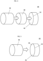
- a galvanic isolator 48 is disposed between the heat exchanger tube 38 and the end sheet 44 at the tube opening 46, as shown in FIG. 4 .
- FIG. 4 In a first embodiment, illustrated in FIG.
- the galvanic isolator 48 is a very thin non-compressible sleeve or insert that is installed into the tube opening 46 prior to installation of the heat exchanger tube 38 into the tube opening 46.
- the heat exchanger tube 38 is then installed into the tube opening 46 such that the galvanic isolator 48 is radially between the heat exchanger tube 38 and an opening wall 50 of the tube opening 46.
- the fit between the evaporator tube 38 and the opening wall 50 is a close fit such that the tube opening 46 is sealed.
- the sleeve may be formed from a non-compressible polymeric or non-metallic material, and in some embodiments has a thickness in the range of 0.0005" to 0.001".
- Utilizing a thin galvanic isolator 48 allows for use of existing spacing of heat exchanger tubes 38 in the heat exchanger, without having to compensate for the presence of the galvanic isolator 48, which may affect heat exchanger performance. While in the embodiment of FIG. 4 the galvanic isolator 48 is installed into the tube opening 46, in other embodiments the galvanic isolator 48 may be installed to the evaporator tube 38 prior to the heat exchanger tube 38 being into the tube opening 46.
- the galvanic isolator 48 is a coating applied directly to the opening wall 50 of the tube opening 46 prior to installation of the heat exchanger tube 38 into the tube opening 46.
- the coating material is, for example, polytetrafluoroethylene (PTFE) material applied by, for example, a spray or dip process.
- PTFE polytetrafluoroethylene
- it is desired that the coating is thin, in the range of 0.0005" to 0.001" thickness, so that the spacing of the heat exchanger tubes 38 will not be affected by the use of the galvanic isolator 48.
- the coating is not limited to PTFE material, and other thin coatings such as nano coatings or the like may be suitable.
- the coating is applied to the opening wall 50 of the tube opening 46
- coating may be applied instead to the heat exchanger tube 38 prior to installation of the heat exchanger tube 38 into the tube opening 46.
- the coating may be applied to both the heat exchanger tube 38 and the opening wall 50 prior to installation of the heat exchanger tube 28 into the tube opening 46.
- galvanic isolator 48 prevents (or at least mitigates) the galvanic pair from forming between the end sheet 44 and the heat exchanger tube 38, thus preventing (or at least mitigating) corrosion of the heat exchanger tube 38, which leads to an extension of the service life of the heat exchanger.
Landscapes
- Engineering & Computer Science (AREA)
- Physics & Mathematics (AREA)
- Thermal Sciences (AREA)
- Mechanical Engineering (AREA)
- General Engineering & Computer Science (AREA)
- Heat-Exchange Devices With Radiators And Conduit Assemblies (AREA)
Abstract
Description
- The present invention pertains to the art of heat exchangers, and more specifically to corrosion mitigation for water cooled chillers.
- In a water-cooled chiller, a flow of refrigerant is directed through one or more shell and tube heat exchangers, such as an evaporator and a condenser, via a plurality of heat exchanger tubes. The heat exchanger tubes are exposed to water inside the heat exchanger, which is used as a heat transfer fluid.
- These heat exchanger tubes are suspended within the shell of the chiller, passing through steel end plates. An issue with galvanic corrosion may arise when the heat exchanger tubes are formed from aluminum. The steel construction is advantageous for medium to large chillers because of its strength given the size of the units. The use of aluminum heat exchanger tubes allows for more technical and intricate shapes and features of the tubes. The steel to aluminum galvanic pair, if not mitigated, is very strong and highly detrimental to the aluminum heat exchanger tubes.
- A first aspect of the invention provides a heat exchanger including a heat exchanger shell formed from a first metal material, and a plurality of heat exchanger tubes extending through a plurality of tube openings in the heat exchanger shell. The plurality of heat exchanger tubes are formed from a second metal material different from the first metal material. A galvanic isolator is located at each tube opening of the plurality of tube openings, radially between the tube opening and the corresponding heat exchanger tube of the plurality of heat exchanger tubes. The galvanic isolator is configured to mitigate a galvanic reaction between the heat exchanger shell and the plurality of heat exchanger tubes.
- The heat exchanger shell may be formed from steel, and the plurality of heat exchanger tubes are formed from aluminum.
- The galvanic isolator may be formed from a non-metallic material.
- The galvanic isolator may be sleeve installed to one of the plurality of tube openings or the plurality of heat exchanger tubes prior to installation of the plurality of heat exchanger tubes into the plurality of tube openings.
- The galvanic isolator may be a coating applied to one of the plurality of tube openings or the plurality of heat exchanger tubes prior to installation of the plurality of heat exchanger tubes into the plurality of tube openings.
- The coating may be a polytetrafluoroethylene (PTFE) material.
- The galvanic isolator may have a thickness in a range of 0.0005 inches to 0.001 inches.
- Installation of the plurality of heat exchanger tubes into the plurality of tube openings may seal the plurality of tube openings.
- A second aspect of the invention provides a chiller system including a refrigerant circuit having a flow of refrigerant circulating therethrough, and a fluid circuit having a flow of heat transfer fluid circulating therethrough. The fluid circuit is operably connected to the refrigerant circuit at a heat exchanger assembly to transfer thermal energy between the flow of refrigerant and the fluid circuit. The heat exchanger assembly includes a heat exchanger shell formed from a first metal material, and a plurality of heat exchanger tubes extending through a plurality of tube openings in the heat exchanger shell. The plurality of heat exchanger tubes are formed from a second metal material different from the first metal material. A galvanic isolator is located at each tube opening of the plurality of tube openings, radially between the tube opening and the corresponding evaporator tube of the plurality of heat exchanger tubes. The galvanic isolator is configured to mitigate a galvanic reaction between the heat exchanger shell and the plurality of heat exchanger tubes.
- The heat exchanger shell may be formed from steel, and the plurality of heat exchanger tubes are formed from aluminum.
- The galvanic isolator may be formed from a non-metallic material.
- The galvanic isolator may be sleeve installed to one of the plurality of tube openings or the plurality of heat exchanger tubes prior to installation of the plurality of heat exchanger tubes into the plurality of tube openings.
- The galvanic isolator may be a coating applied to one of the plurality of tube openings or the plurality of heat exchanger tubes prior to installation of the plurality of heat exchanger tubes into the plurality of tube openings.
- The coating may be a polytetrafluoroethylene (PTFE) material.
- The galvanic isolator may have a thickness in a range of 0.0005 to 0.001 inches.
- Installation of the plurality of heat exchanger tubes into the plurality of tube openings may seal the plurality of tube openings.
- The heat transfer fluid may be water.
- A third aspect of the invention provides a method of assembling a heat exchanger including defining a heat exchanger shell formed from a first metal material, the heat exchanger shell having a plurality of tube openings formed therein, and providing a plurality of heat exchanger tubes formed from a second metal material different from the first metal material. A non-metallic galvanic isolator is installed to one of an opening wall of the plurality of tube openings or the plurality of heat exchanger tubes. The plurality of heat exchanger tubes are installed into the plurality of tube openings, such that the galvanic isolator is located radially between the heat exchanger tube and the opening wall.
- The galvanic isolator may be a polymeric sleeve.
- The galvanic isolator may be a coating applied to one of the opening wall or the heat exchanger tube.
- The following descriptions should not be considered limiting in any way. With reference to the accompanying drawings, like elements are numbered alike:
-
FIG. 1 is a schematic illustration of a chiller; -
FIG. 2 is a cross-sectional view of a heat exchanger; -
FIG. 3 is an illustration of an end sheet of heat exchanger shell; -
FIG. 4 illustrates a galvanic isolator for a heat exchanger; and -
FIG. 5 illustrates another galvanic isolator for a heat exchanger. - A detailed description of one or more embodiments of the disclosed apparatus and method are presented herein by way of exemplification and not limitation with reference to the Figures.
- Illustrated in
FIG. 1 is an embodiment of a heating, ventilation and air conditioning (HVAC) system, for example achiller 10. Thechiller 10 includes arefrigerant circuit 12, having a flow ofrefrigerant 14 circulating therethrough. Acompressor 16, acondenser 18, anexpansion device 20, and anevaporator 22 arranged in series, with the flow ofrefrigerant 14 flowing through the components in sequence. Thechiller 10 further includes afluid circuit 24 operably connected to therefrigerant circuit 12 at theevaporator 22. Thefluid circuit 24 has a flow of heat transfer fluid, such as a flow ofwater 26 circulating therethrough. The flow ofwater 26 circulates between theevaporator 22 and a heat exchanger, for example, afan coil 28. The flow ofwater 26 is cooled at theevaporator 22 via an exchange of thermal energy with the flow ofrefrigerant 14. The cooled flow ofwater 26 is circulated to thefan coil 28 where it absorbs thermal energy from a flow orair 30 to provide cooling to a conditionedspace 32. In some embodiments, afan 34 aids the exchange of thermal energy at thefan coil 28. Additionally, in some embodiments, thecondenser 18 is water cooled, and utilizes a condenser flow ofwater 60 to reject thermal energy from the flow ofrefrigerant 14 to condense the flow ofrefrigerant 14. - Referring now to
FIG. 2 , a cross-sectional view of a heat exchanger, such as theevaporator 22 or thecondenser 18 of thechiller 10. The heat exchanger includes aheat exchanger shell 36 that contains a plurality ofheat exchanger tubes 38 through which the flow ofrefrigerant 14 is directed through the heat exchanger. In some embodiments, theheat exchanger tubes 38 are formed from an aluminum material. The flow ofwater 26 enters the heat exchanger via awater inlet 40 and exits the heat exchanger after being either heated in the case of thecondenser 18, or cooled in the case of theevaporator 22, via the flow ofrefrigerant 14 at awater outlet 42. In some embodiments, such as illustrated inFIG. 2 , the flow ofwater 26 flows over theheat exchanger 38 via gravity. In other embodiments, the heat exchanger is flooded, in which theheat exchanger shell 36 is substantially filled with the flow ofwater 26. - Illustrated in
FIG. 3 is an embodiment of anend sheet 44 of theheat exchanger shell 36. Theend sheet 44 is formed from steel and includes a plurality oftube openings 46 through which theheat exchanger tubes 38 are installed. To prevent (or at least mitigate) a galvanic reaction between theend sheet 44 and theheat exchanger tubes 38 when theheat exchanger tubes 38 are exposed to the flow ofwater 26, agalvanic isolator 48 is disposed between theheat exchanger tube 38 and theend sheet 44 at thetube opening 46, as shown inFIG. 4 . In a first embodiment, illustrated inFIG. 4 , thegalvanic isolator 48 is a very thin non-compressible sleeve or insert that is installed into thetube opening 46 prior to installation of theheat exchanger tube 38 into thetube opening 46. Theheat exchanger tube 38 is then installed into thetube opening 46 such that thegalvanic isolator 48 is radially between theheat exchanger tube 38 and an openingwall 50 of thetube opening 46. The fit between theevaporator tube 38 and the openingwall 50 is a close fit such that thetube opening 46 is sealed. The sleeve may be formed from a non-compressible polymeric or non-metallic material, and in some embodiments has a thickness in the range of 0.0005" to 0.001". - Utilizing a thin
galvanic isolator 48 allows for use of existing spacing ofheat exchanger tubes 38 in the heat exchanger, without having to compensate for the presence of thegalvanic isolator 48, which may affect heat exchanger performance. While in the embodiment ofFIG. 4 thegalvanic isolator 48 is installed into thetube opening 46, in other embodiments thegalvanic isolator 48 may be installed to theevaporator tube 38 prior to theheat exchanger tube 38 being into thetube opening 46. - In another embodiment, illustrated in
FIG. 5 , thegalvanic isolator 48 is a coating applied directly to the openingwall 50 of thetube opening 46 prior to installation of theheat exchanger tube 38 into thetube opening 46. In some embodiments the coating material is, for example, polytetrafluoroethylene (PTFE) material applied by, for example, a spray or dip process. As with the sleeve, it is desired that the coating is thin, in the range of 0.0005" to 0.001" thickness, so that the spacing of theheat exchanger tubes 38 will not be affected by the use of thegalvanic isolator 48. One skilled in the art will readily appreciate that the coating is not limited to PTFE material, and other thin coatings such as nano coatings or the like may be suitable. While in the embodiment ofFIG. 5 , the coating is applied to the openingwall 50 of thetube opening 46, one skilled in the art will appreciate that that coating may be applied instead to theheat exchanger tube 38 prior to installation of theheat exchanger tube 38 into thetube opening 46. Further, in some embodiments the coating may be applied to both theheat exchanger tube 38 and the openingwall 50 prior to installation of theheat exchanger tube 28 into thetube opening 46. - Use of the
galvanic isolator 48 prevents (or at least mitigates) the galvanic pair from forming between theend sheet 44 and theheat exchanger tube 38, thus preventing (or at least mitigating) corrosion of theheat exchanger tube 38, which leads to an extension of the service life of the heat exchanger. - The term "about" is intended to include the degree of error associated with measurement of the particular quantity based upon the equipment available at the time of filing the application.
- The terminology used herein is for the purpose of describing particular embodiments only and is not intended to be limiting of the present invention. As used herein, the singular forms "a", "an" and "the" are intended to include the plural forms as well, unless the context clearly indicates otherwise. It will be further understood that the terms "comprises" and/or "comprising," when used in this specification, specify the presence of stated features, integers, steps, operations, elements, and/or components, but do not preclude the presence or addition of one or more other features, integers, steps, operations, element components, and/or groups thereof.
- While the present invention has been described with reference to an exemplary embodiment or embodiments, it will be understood by those skilled in the art that various changes may be made and equivalents may be substituted for elements thereof without departing from the scope of the present invention. In addition, many modifications may be made to adapt a particular situation or material to the teachings of the present invention without departing from the scope thereof. Therefore, it is intended that the present invention not be limited to the particular embodiment disclosed, but that the present invention will include all embodiments falling within the scope of the claims.
- The following clauses set out features of the invention which may or may not be claimed but which may form the basis for future amendments and/or a divisional application:
- 1. A chiller system comprising:
- a refrigerant circuit having a flow of refrigerant circulating therethrough;
- a fluid circuit having a flow of heat transfer fluid circulating therethrough, the fluid circuit operably connected to the refrigerant circuit at a heat exchanger assembly to transfer thermal energy between the flow of refrigerant and the fluid circuit, the heat exchanger assembly comprising:
a heat exchanger shell formed from a first metal material;- a plurality of heat exchanger tubes extending through a plurality of tube openings in the heat exchanger shell, the plurality of heat exchanger tubes formed from a second metal material different from the first metal material; and
- a galvanic isolator disposed at each tube opening of the plurality of tube openings, radially between the tube opening and the corresponding evaporator tube of the plurality of heat exchanger tubes, the galvanic isolator configured to mitigate a galvanic reaction between the heat exchanger shell and the plurality of heat exchanger tubes.
- 2. The chiller system of clause 1, wherein:
- the heat exchanger shell is formed from steel; and
- the plurality of heat exchanger tubes are formed from aluminum.
- 3. The chiller system of clause 1, wherein the galvanic isolator is formed from a non-metallic material.
- 4. The chiller system of clause 1, wherein the galvanic isolator is sleeve installed to one of the plurality of tube openings or the plurality of heat exchanger tubes prior to installation of the plurality of heat exchanger tubes into the plurality of tube openings.
- 5. The chiller system of clause 1, wherein the galvanic isolator is a coating applied to one of the plurality of tube openings or the plurality of heat exchanger tubes prior to installation of the plurality of heat exchanger tubes into the plurality of tube openings.
- 6. The chiller system of clause 5, wherein the coating is a polytetrafluoroethylene (PTFE) material.
- 7. The chiller system of clause 1, wherein the galvanic isolator has a thickness in a range of 0.0005 to 0.001 inches.
- 8. The chiller system of clause 1, wherein installation of the plurality of heat exchanger tubes into the plurality of tube openings seals the plurality of tube openings.
- 9. The chiller system of clause 1, wherein the heat transfer fluid is water.
Claims (13)
- A heat exchanger (22, 18) comprising:a heat exchanger shell (36) formed from a first metal material;a plurality of heat exchanger tubes (38) extending through a plurality of tube openings (46) in the heat exchanger shell (36), the plurality of heat exchanger tubes (38) being formed from a second metal material different from the first metal material; anda galvanic isolator (48) disposed at each tube opening of the plurality of tube openings (46), radially between the tube opening and the corresponding heat exchanger tube of the plurality of heat exchanger tubes (38), the galvanic isolator (48) being configured to mitigate a galvanic reaction between the heat exchanger shell (36) and the plurality of heat exchanger tubes (38).
- The heat exchanger (22, 18) of claim 1, wherein:the heat exchanger shell (36) is formed from steel; andthe plurality of heat exchanger tubes (38) are formed from aluminum.
- The heat exchanger (22, 18) of any preceding claim, wherein the galvanic isolator (48) is formed from a non-metallic material.
- The heat exchanger (22, 18) of any preceding claim, wherein the galvanic isolator (48) is sleeve installed to one of the plurality of tube openings (46) or the plurality of heat exchanger tubes (38) prior to installation of the plurality of heat exchanger tubes (38) into the plurality of tube openings (46).
- The heat exchanger (22, 18) of any of claims 1 to 3, wherein the galvanic isolator (48) is a coating applied to one of the plurality of tube openings (46) or the plurality of heat exchanger tubes (38) prior to installation of the plurality of heat exchanger tubes (38) into the plurality of tube openings (46).
- The heat exchanger (22, 18) of claim 5, wherein the coating is a polytetrafluoroethylene (PTFE) material.
- The heat exchanger (22, 18) of any preceding claim, wherein the galvanic isolator (48) has a thickness in a range of 0.0005 to 0.001 inches.
- The heat exchanger (22, 18) of any preceding claim, wherein installation of the plurality of heat exchanger tubes (38) into the plurality of tube openings (46) seals the plurality of tube openings (46).
- A chiller system (10) comprising:a refrigerant circuit (12) having a flow of refrigerant (14) circulating therethrough;a fluid circuit (24) having a flow of heat transfer fluid (26) circulating therethrough, the fluid circuit (24) being operably connected to the refrigerant circuit (12) at a heat exchanger (22, 18) to transfer thermal energy between the flow of refrigerant (14) and the fluid circuit (24), the heat exchanger (22, 18) being a heat exchanger (22, 18) according to any preceding claim.
- The chiller system (10) of claim 9, wherein the heat transfer fluid is 5 water.
- A method of assembling a heat exchanger (22, 18) comprising:defining a heat exchanger shell (36) formed from a first metal material, the heat exchanger shell (36) having a plurality of tube openings (46) formed therein;providing a plurality of heat exchanger tubes (38) formed from a second metal 10 material different from the first metal material;installing a non-metallic galvanic isolator (48) to one of an opening wall (50) of the plurality of tube openings (46) or the plurality of heat exchanger tubes (38); andinstalling the plurality of heat exchanger tubes (38) into the plurality of tube openings (46), such that the galvanic isolator (48) is disposed radially between the heat exchanger tube and the opening wall (50).
- The method of claim 11, wherein the galvanic isolator (48) is a 5 polymeric sleeve.
- The method of claim 11, wherein the galvanic isolator (48) is a coating applied to one of the opening wall (50) or the heat exchanger tube.
Applications Claiming Priority (1)
| Application Number | Priority Date | Filing Date | Title |
|---|---|---|---|
| US202263354388P | 2022-06-22 | 2022-06-22 |
Publications (1)
| Publication Number | Publication Date |
|---|---|
| EP4296600A1 true EP4296600A1 (en) | 2023-12-27 |
Family
ID=86851645
Family Applications (1)
| Application Number | Title | Priority Date | Filing Date |
|---|---|---|---|
| EP23179347.2A Pending EP4296600A1 (en) | 2022-06-22 | 2023-06-14 | Shell and tube isolation in heat exchanger |
Country Status (3)
| Country | Link |
|---|---|
| US (1) | US20230417496A1 (en) |
| EP (1) | EP4296600A1 (en) |
| CN (1) | CN117268158A (en) |
Citations (4)
| Publication number | Priority date | Publication date | Assignee | Title |
|---|---|---|---|---|
| US4776391A (en) * | 1979-10-04 | 1988-10-11 | Heat Exchanger Industries, Inc. | Heat exchanger method and apparatus |
| US5323849A (en) * | 1993-04-21 | 1994-06-28 | The United States Of America As Represented By The Secretary Of The Navy | Corrosion resistant shell and tube heat exchanger and a method of repairing the same |
| US20160046820A1 (en) * | 2012-07-17 | 2016-02-18 | Her Majesty The Queen In Right Of Canada As Rep. By The Minister Of Natural Resources | Method and composite for preparing heat exchangers for corrosive environments |
| WO2022020117A1 (en) * | 2020-07-21 | 2022-01-27 | Cg Thermal, Llc | Corrosion resistant heat exchanger and tube sheet therefor |
Family Cites Families (3)
| Publication number | Priority date | Publication date | Assignee | Title |
|---|---|---|---|---|
| BE561597A (en) * | 1957-03-08 | |||
| NL293689A (en) * | 1962-08-27 | |||
| US3923314A (en) * | 1973-12-06 | 1975-12-02 | Carborundum Co | Non-rigid seal for joining silicon carbide tubes and tube sheets in heat exchangers |
-
2023
- 2023-06-14 EP EP23179347.2A patent/EP4296600A1/en active Pending
- 2023-06-20 CN CN202310732168.0A patent/CN117268158A/en active Pending
- 2023-06-22 US US18/339,445 patent/US20230417496A1/en active Pending
Patent Citations (4)
| Publication number | Priority date | Publication date | Assignee | Title |
|---|---|---|---|---|
| US4776391A (en) * | 1979-10-04 | 1988-10-11 | Heat Exchanger Industries, Inc. | Heat exchanger method and apparatus |
| US5323849A (en) * | 1993-04-21 | 1994-06-28 | The United States Of America As Represented By The Secretary Of The Navy | Corrosion resistant shell and tube heat exchanger and a method of repairing the same |
| US20160046820A1 (en) * | 2012-07-17 | 2016-02-18 | Her Majesty The Queen In Right Of Canada As Rep. By The Minister Of Natural Resources | Method and composite for preparing heat exchangers for corrosive environments |
| WO2022020117A1 (en) * | 2020-07-21 | 2022-01-27 | Cg Thermal, Llc | Corrosion resistant heat exchanger and tube sheet therefor |
Also Published As
| Publication number | Publication date |
|---|---|
| CN117268158A (en) | 2023-12-22 |
| US20230417496A1 (en) | 2023-12-28 |
Similar Documents
| Publication | Publication Date | Title |
|---|---|---|
| CN116261308B (en) | Electronic device cooling system | |
| WO2008064257A2 (en) | Method for brazing and hot forming a multichannel heat exchanger, the hot forming using the heating energy of the brazing step | |
| EP1439365A2 (en) | Heat exchanger | |
| US11333369B2 (en) | Refrigerant distributor, heat exchanger, and air-conditioning apparatus | |
| WO2016144014A1 (en) | Turbulence generating device | |
| EP4155655B1 (en) | Refrigerant distributor, heat exchanger, and air conditioner | |
| TW201727177A (en) | Heat exchanger with water tank | |
| EP3021064A1 (en) | Heat exchanger, and heat pump device | |
| US11236946B2 (en) | Microchannel heat exchanger | |
| US4967830A (en) | Arcuate tubular evaporator heat exchanger | |
| CN104254740A (en) | air conditioner | |
| US20230417496A1 (en) | Shell and tube isolation in heat exchanger | |
| Webb et al. | Brazed aluminum condensers for residential air conditioning | |
| US20250109864A1 (en) | Indoor unit of hvac apparatus, and hvac apparatus | |
| US4102152A (en) | Heat exchange device for air conditioners | |
| US20200271402A1 (en) | Helical insert for shell and tube heat exchanger | |
| CN114440326A (en) | Air condensing units cooling device and air conditioner | |
| CN117781516A (en) | heat exchanger | |
| CN213839126U (en) | Hydraulic tank thermostat and hydraulic transmission system | |
| CN116734652A (en) | Non-metallic partitions for heat exchangers | |
| KR20170000892U (en) | Heat exchanger | |
| KR102396705B1 (en) | Systems and methods for ventilation enclosures | |
| CN104254739B (en) | The outdoor unit of air-conditioning device | |
| US12453043B2 (en) | Mechanically expanded microfin tube liquid cooled heat sink | |
| EP3770535A1 (en) | Heat exchanger, refrigeration cycle device, and air conditioning device |
Legal Events
| Date | Code | Title | Description |
|---|---|---|---|
| PUAI | Public reference made under article 153(3) epc to a published international application that has entered the european phase |
Free format text: ORIGINAL CODE: 0009012 |
|
| STAA | Information on the status of an ep patent application or granted ep patent |
Free format text: STATUS: THE APPLICATION HAS BEEN PUBLISHED |
|
| AK | Designated contracting states |
Kind code of ref document: A1 Designated state(s): AL AT BE BG CH CY CZ DE DK EE ES FI FR GB GR HR HU IE IS IT LI LT LU LV MC ME MK MT NL NO PL PT RO RS SE SI SK SM TR |
|
| STAA | Information on the status of an ep patent application or granted ep patent |
Free format text: STATUS: REQUEST FOR EXAMINATION WAS MADE |
|
| 17P | Request for examination filed |
Effective date: 20240626 |
|
| RBV | Designated contracting states (corrected) |
Designated state(s): AL AT BE BG CH CY CZ DE DK EE ES FI FR GB GR HR HU IE IS IT LI LT LU LV MC ME MK MT NL NO PL PT RO RS SE SI SK SM TR |
|
| STAA | Information on the status of an ep patent application or granted ep patent |
Free format text: STATUS: EXAMINATION IS IN PROGRESS |
|
| 17Q | First examination report despatched |
Effective date: 20241220 |