EP4296585A1 - Air conditioner - Google Patents
Air conditioner Download PDFInfo
- Publication number
- EP4296585A1 EP4296585A1 EP23178681.5A EP23178681A EP4296585A1 EP 4296585 A1 EP4296585 A1 EP 4296585A1 EP 23178681 A EP23178681 A EP 23178681A EP 4296585 A1 EP4296585 A1 EP 4296585A1
- Authority
- EP
- European Patent Office
- Prior art keywords
- indoor
- air conditioner
- refrigerant
- rotational frequency
- outdoor
- Prior art date
- Legal status (The legal status is an assumption and is not a legal conclusion. Google has not performed a legal analysis and makes no representation as to the accuracy of the status listed.)
- Granted
Links
Images

Classifications
-
- F—MECHANICAL ENGINEERING; LIGHTING; HEATING; WEAPONS; BLASTING
- F24—HEATING; RANGES; VENTILATING
- F24F—AIR-CONDITIONING; AIR-HUMIDIFICATION; VENTILATION; USE OF AIR CURRENTS FOR SCREENING
- F24F11/00—Control or safety arrangements
- F24F11/30—Control or safety arrangements for purposes related to the operation of the system, e.g. for safety or monitoring
- F24F11/32—Responding to malfunctions or emergencies
- F24F11/36—Responding to malfunctions or emergencies to leakage of heat-exchange fluid
-
- F—MECHANICAL ENGINEERING; LIGHTING; HEATING; WEAPONS; BLASTING
- F24—HEATING; RANGES; VENTILATING
- F24F—AIR-CONDITIONING; AIR-HUMIDIFICATION; VENTILATION; USE OF AIR CURRENTS FOR SCREENING
- F24F11/00—Control or safety arrangements
- F24F11/70—Control systems characterised by their outputs; Constructional details thereof
- F24F11/72—Control systems characterised by their outputs; Constructional details thereof for controlling the supply of treated air, e.g. its pressure
- F24F11/74—Control systems characterised by their outputs; Constructional details thereof for controlling the supply of treated air, e.g. its pressure for controlling air flow rate or air velocity
- F24F11/77—Control systems characterised by their outputs; Constructional details thereof for controlling the supply of treated air, e.g. its pressure for controlling air flow rate or air velocity by controlling the speed of ventilators
-
- F—MECHANICAL ENGINEERING; LIGHTING; HEATING; WEAPONS; BLASTING
- F25—REFRIGERATION OR COOLING; COMBINED HEATING AND REFRIGERATION SYSTEMS; HEAT PUMP SYSTEMS; MANUFACTURE OR STORAGE OF ICE; LIQUEFACTION SOLIDIFICATION OF GASES
- F25B—REFRIGERATION MACHINES, PLANTS OR SYSTEMS; COMBINED HEATING AND REFRIGERATION SYSTEMS; HEAT PUMP SYSTEMS
- F25B13/00—Compression machines, plants or systems, with reversible cycle
-
- F—MECHANICAL ENGINEERING; LIGHTING; HEATING; WEAPONS; BLASTING
- F25—REFRIGERATION OR COOLING; COMBINED HEATING AND REFRIGERATION SYSTEMS; HEAT PUMP SYSTEMS; MANUFACTURE OR STORAGE OF ICE; LIQUEFACTION SOLIDIFICATION OF GASES
- F25B—REFRIGERATION MACHINES, PLANTS OR SYSTEMS; COMBINED HEATING AND REFRIGERATION SYSTEMS; HEAT PUMP SYSTEMS
- F25B41/00—Fluid-circulation arrangements
- F25B41/20—Disposition of valves, e.g. of on-off valves or flow control valves
- F25B41/24—Arrangement of shut-off valves for disconnecting a part of the refrigerant cycle, e.g. an outdoor part
-
- F—MECHANICAL ENGINEERING; LIGHTING; HEATING; WEAPONS; BLASTING
- F25—REFRIGERATION OR COOLING; COMBINED HEATING AND REFRIGERATION SYSTEMS; HEAT PUMP SYSTEMS; MANUFACTURE OR STORAGE OF ICE; LIQUEFACTION SOLIDIFICATION OF GASES
- F25B—REFRIGERATION MACHINES, PLANTS OR SYSTEMS; COMBINED HEATING AND REFRIGERATION SYSTEMS; HEAT PUMP SYSTEMS
- F25B49/00—Arrangement or mounting of control or safety devices
- F25B49/02—Arrangement or mounting of control or safety devices for compression type machines, plants or systems
-
- F—MECHANICAL ENGINEERING; LIGHTING; HEATING; WEAPONS; BLASTING
- F25—REFRIGERATION OR COOLING; COMBINED HEATING AND REFRIGERATION SYSTEMS; HEAT PUMP SYSTEMS; MANUFACTURE OR STORAGE OF ICE; LIQUEFACTION SOLIDIFICATION OF GASES
- F25B—REFRIGERATION MACHINES, PLANTS OR SYSTEMS; COMBINED HEATING AND REFRIGERATION SYSTEMS; HEAT PUMP SYSTEMS
- F25B2400/00—Component parts or details not otherwise provided for in this subclass
- F25B2400/12—Inflammable refrigerants
-
- F—MECHANICAL ENGINEERING; LIGHTING; HEATING; WEAPONS; BLASTING
- F25—REFRIGERATION OR COOLING; COMBINED HEATING AND REFRIGERATION SYSTEMS; HEAT PUMP SYSTEMS; MANUFACTURE OR STORAGE OF ICE; LIQUEFACTION SOLIDIFICATION OF GASES
- F25B—REFRIGERATION MACHINES, PLANTS OR SYSTEMS; COMBINED HEATING AND REFRIGERATION SYSTEMS; HEAT PUMP SYSTEMS
- F25B2500/00—Problems to be solved
- F25B2500/22—Preventing, detecting or repairing leaks of refrigeration fluids
- F25B2500/221—Preventing leaks from developing
-
- F—MECHANICAL ENGINEERING; LIGHTING; HEATING; WEAPONS; BLASTING
- F25—REFRIGERATION OR COOLING; COMBINED HEATING AND REFRIGERATION SYSTEMS; HEAT PUMP SYSTEMS; MANUFACTURE OR STORAGE OF ICE; LIQUEFACTION SOLIDIFICATION OF GASES
- F25B—REFRIGERATION MACHINES, PLANTS OR SYSTEMS; COMBINED HEATING AND REFRIGERATION SYSTEMS; HEAT PUMP SYSTEMS
- F25B2600/00—Control issues
- F25B2600/02—Compressor control
- F25B2600/025—Compressor control by controlling speed
- F25B2600/0251—Compressor control by controlling speed with on-off operation
-
- F—MECHANICAL ENGINEERING; LIGHTING; HEATING; WEAPONS; BLASTING
- F25—REFRIGERATION OR COOLING; COMBINED HEATING AND REFRIGERATION SYSTEMS; HEAT PUMP SYSTEMS; MANUFACTURE OR STORAGE OF ICE; LIQUEFACTION SOLIDIFICATION OF GASES
- F25B—REFRIGERATION MACHINES, PLANTS OR SYSTEMS; COMBINED HEATING AND REFRIGERATION SYSTEMS; HEAT PUMP SYSTEMS
- F25B2600/00—Control issues
- F25B2600/11—Fan speed control
- F25B2600/111—Fan speed control of condenser fans
-
- F—MECHANICAL ENGINEERING; LIGHTING; HEATING; WEAPONS; BLASTING
- F25—REFRIGERATION OR COOLING; COMBINED HEATING AND REFRIGERATION SYSTEMS; HEAT PUMP SYSTEMS; MANUFACTURE OR STORAGE OF ICE; LIQUEFACTION SOLIDIFICATION OF GASES
- F25B—REFRIGERATION MACHINES, PLANTS OR SYSTEMS; COMBINED HEATING AND REFRIGERATION SYSTEMS; HEAT PUMP SYSTEMS
- F25B2600/00—Control issues
- F25B2600/25—Control of valves
- F25B2600/2519—On-off valves
Definitions
- the present disclosure relates to an air conditioner.
- PTL 1 discloses an air conditioner in which electrical components are positioned in an upper part of a casing so that the electrical components are positioned higher than a heat exchanger.
- the electrical components which may become an ignition source for the leaking refrigerant, are at a level higher than the heat exchanger, and are separated above the leaking refrigerant, it is possible to prevent the leaking refrigerant from getting into the electric components and catching fire, reliably. In other words, safety against a leakage of a flammable refrigerant is ensured.
- An air conditioner includes: an outdoor unit that includes a compressor, an outdoor heat exchanger, an outdoor fan, and an expansion mechanism; and an indoor unit that includes an indoor heat exchanger and an indoor fan.
- the outdoor unit and the indoor unit together form a refrigeration cycle circuit by being connected by a refrigerant pipe.
- the refrigeration cycle circuit uses a flammable refrigerant, and the compressor is controlled not to start when a driving rotational frequency of the indoor fan is lower than or equal to a predetermined rotational frequency.
- the air conditioner according to the present disclosure controls the compressor not to start when the driving rotational frequency of the indoor fan is lower than or equal to a predetermined rotational frequency, and starts the compressor only when the driving rotational frequency of the indoor fan is higher than the predetermined rotational frequency. Therefore, even when a leakage of the flammable refrigerant occurs, a sufficient airflow can be ensured, and the air inside of the air-conditioned space can be sufficiently stirred. Hence, the flammable refrigerant can be prevented from forming a flammable region.
- air conditioner 1 In the refrigeration cycle circuit in Fig. 1 , air conditioner 1 circulates a flammable refrigerant such as isobutane or propane, and performs air conditioning such as heating or cooling inside of an air-conditioned space in which indoor unit 10 is installed. Note that devices that are not used in the descriptions, such as an accumulator, are not illustrated in Fig. 1 , but air conditioner 1 may include such other devices not illustrated.
- a flammable refrigerant such as isobutane or propane
- Indoor unit 10 includes indoor heat exchanger 11 and indoor fan 12.
- Indoor heat exchanger 11 is, for example, a finned tube heat exchanger, and inside of which is provided with a flow channel through which the refrigerant is passed.
- Indoor fan 12 is, for example, a cross flow fan that blows out the air by using a motor, not illustrated, to rotate an impeller.
- Indoor fan 12 suctions the air from the air-conditioned space into indoor unit 10, and exchanges the heat between the refrigerant inside of indoor heat exchanger 11 and the suctioned air. The air having the heat exchanged with the refrigerant is returned to the outside of indoor unit 10, and conditions the air inside of the air-conditioned space.
- Outdoor unit 20 includes compressor 21, four-way valve 22, outdoor heat exchanger 23, outdoor fan 24, and expansion mechanism 25.
- Compressor 21 is, for example, sealed compressor 21, and suctions, compresses, and discharges gas refrigerant toward four-way valve 22.
- Four-way valve 22 is capable of switching a flow path of the refrigerant flowing into compressor 21 and a flow path of the refrigerant discharged from compressor 21.
- four-way valve 22 switches the operation of indoor unit 10 between a cooling operation and a heating operation. For example, when four-way valve 22 causes the refrigerant to flow in the direction of the arrow illustrated in Fig. 1 , indoor unit 10 performs the cooling operation.
- Outdoor heat exchanger 23 is, for example, a finned tube heat exchanger, and inside of which is provided with a flow channel through which the refrigerant is passed.
- Indoor unit 10 and outdoor unit 20 are connected to each other by gas-side connection pipe 30 connecting a gas side of indoor unit 10 and a gas side of outdoor unit 20, and liquid-side connection pipe 31 connecting a liquid side of indoor unit 10 and a liquid side of outdoor unit 20.
- Gas-side three-way valve 34 and liquid-side two-way valve 33 are inserted in gas-side connection pipe 30 and in liquid-side connection pipe 31, respectively.
- Indoor unit 10 and outdoor unit 20 are connected to each other via liquid-side two-way valve 33 and gas-side three-way valve 34.
- Liquid-side two-way valve 33 and gas-side three-way valve 34 are manually opened when the work connecting outdoor unit 20 and indoor unit 10 is finished. It is also possible to configure liquid-side two-way valve 33 and gas-side three-way valve 34 to open and close automatically under the control of outdoor control unit 41 or indoor control unit 40.
- Safety shutoff valves 32 are provided on an inlet side and an outlet side of indoor heat exchanger 11, respectively. Safety shutoff valves 32 shut off gas-side connection pipe 30 and liquid-side connection pipe 31, when indoor heat exchanger 11 is experiencing a leakage of the refrigerant, and prevents the refrigerant inside gas-side connection pipe 30 and liquid-side connection pipe 31 from being sent to indoor heat exchanger 11.
- Safety shutoff valves 32 may also be provided outside of indoor unit 10, or may be provided closer to outdoor unit 20 than liquid-side two-way valve 33 and gas-side three-way valve 34.
- indoor unit 10 includes indoor control unit 40.
- Outdoor unit 20 includes outdoor control unit 41.
- Indoor control unit 40 and outdoor control unit 41 are configured to be able to communicate with each other.
- Indoor control unit 40 controls the rotation of indoor fan 12. Indoor control unit 40 also controls to open and to close safety shutoff valves 32.
- indoor fan 12 fails to achieve a sufficient airflow and fails to stir the air inside of the air-conditioned space sufficiently in case of a leakage of the flammable refrigerant, so that the flammable refrigerant may form a flammable region.
- indoor control unit 40 transmits the calculation result to outdoor control unit 41, and outdoor control unit 41 controls not to start compressor 21.
- Indoor control unit 40 may be configured to, when the driving rotational frequency of indoor fan 12 is lower than or equal to a predetermined rotational frequency, or when the airflow of indoor fan 12 is less than or equal to a predetermined airflow, control not to drive compressor 21 and to close safety shutoff valves 32.
- Indoor control unit 40 may also control to keep indoor fan 12 driving while the air conditioner is not operating.
- the air conditioner may include an auxiliary power supply (not illustrated) such as a battery.
- the auxiliary power supply is installed in an indoor unit, for example, and serves to supply the power for driving indoor fan 12 when the supply of commercial power stops due to a power failure, for example.
- indoor control unit 40 controls to drive indoor fan 12.
- Indoor control unit 40 detects the driving rotational frequency of indoor fan 12, and determines whether the driving rotational frequency is lower than or equal to a predetermined rotational frequency (ST2).
- indoor control unit 40 transmits information of the driving rotational frequency of indoor fan 12 to outdoor control unit 41. With this information, outdoor control unit 41 controls not to start compressor 21 (ST3).
- indoor control unit 40 controls to close safety shutoff valves 32 (ST4).
- indoor control unit 40 transmits the information of the driving rotational frequency to outdoor control unit 41, and causes outdoor control unit 41 to drive compressor 21 and outdoor fan 24 (ST5) and to switch four-way valve 22 for the cooling operation or the heating operation.
- air conditioner 1 performs the normal cooling operation or heating operation.
- air conditioner 1 includes outdoor unit 20 that includes compressor 21, outdoor heat exchanger 23, outdoor fan 24, and expansion mechanism 25, and the indoor unit that includes indoor heat exchanger 11 and indoor fan 12.
- Outdoor unit 20 and the indoor unit together form a refrigeration cycle circuit by being connected by a refrigerant pipe, and the refrigeration cycle circuit uses a flammable refrigerant.
- Compressor 21 is controlled not to start when the driving rotational frequency of indoor fan 12 is lower than or equal to a predetermined rotational frequency.
- compressor 21 is started only when the driving rotational frequency of indoor fan 12 is higher than the predetermined rotational frequency, even when a leakage of the flammable refrigerant occurs, a sufficient airflow can be ensured, and the air inside of the air-conditioned space can be stirred sufficiently. Therefore, it is possible to suppress formation of a flammable region by the flammable refrigerant.
- indoor fan 12 Because the airflow and the rotational frequency of indoor fan 12 are in a proportional relationship, when the airflow of indoor fan 12 is greater than a predetermined airflow, a sufficient airflow can be ensured. Therefore, even when a leakage of the flammable refrigerant occurs, the air inside of the air-conditioned space can be stirred sufficiently, and formation of a flammable region by the flammable refrigerant can be suppressed.
- safety shutoff valves 32 are installed in the refrigeration cycle circuit, and safety shutoff valves 32 are controlled to close when the driving rotational frequency of indoor fan 12 is lower than or equal to a predetermined rotational frequency.
- an auxiliary power supply that supplies power to indoor fan 12 when the air conditioner is not receiving power supply may be provided.
Landscapes
- Engineering & Computer Science (AREA)
- Mechanical Engineering (AREA)
- General Engineering & Computer Science (AREA)
- Physics & Mathematics (AREA)
- Thermal Sciences (AREA)
- Chemical & Material Sciences (AREA)
- Combustion & Propulsion (AREA)
- Fluid Mechanics (AREA)
- Air Conditioning Control Device (AREA)
Abstract
Description
- The present disclosure relates to an air conditioner.
-
PTL 1 discloses an air conditioner in which electrical components are positioned in an upper part of a casing so that the electrical components are positioned higher than a heat exchanger. In this arrangement, even if the flammable refrigerant leaks from the heat exchanger and accumulates in the lower part of the casing, because the electrical components, which may become an ignition source for the leaking refrigerant, are at a level higher than the heat exchanger, and are separated above the leaking refrigerant, it is possible to prevent the leaking refrigerant from getting into the electric components and catching fire, reliably. In other words, safety against a leakage of a flammable refrigerant is ensured. - PTL 1:
Japanese Patent No. 3807004 - The present disclosure provides an air conditioner capable of improving safety against a leakage of a flammable refrigerant.
- An air conditioner according to the present disclosure includes: an outdoor unit that includes a compressor, an outdoor heat exchanger, an outdoor fan, and an expansion mechanism; and an indoor unit that includes an indoor heat exchanger and an indoor fan. The outdoor unit and the indoor unit together form a refrigeration cycle circuit by being connected by a refrigerant pipe. The refrigeration cycle circuit uses a flammable refrigerant, and the compressor is controlled not to start when a driving rotational frequency of the indoor fan is lower than or equal to a predetermined rotational frequency.
- The air conditioner according to the present disclosure controls the compressor not to start when the driving rotational frequency of the indoor fan is lower than or equal to a predetermined rotational frequency, and starts the compressor only when the driving rotational frequency of the indoor fan is higher than the predetermined rotational frequency. Therefore, even when a leakage of the flammable refrigerant occurs, a sufficient airflow can be ensured, and the air inside of the air-conditioned space can be sufficiently stirred. Hence, the flammable refrigerant can be prevented from forming a flammable region.
-
-
Fig. 1 is a configuration diagram illustrating a refrigeration cycle circuit of an air conditioner according to a first exemplary embodiment; -
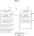
Fig. 2 is a block diagram illustrating a control configuration of the air conditioner according to the first exemplary embodiment; and -
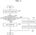
Fig. 3 is a flowchart illustrating an operation of the air conditioner according to the first exemplary embodiment. - At the time when the inventors have arrived at the present disclosure, in the technical field of air conditioners, there has been some disclosures for switching the refrigerant to be used, to a refrigerant having low global warming potential, e.g., isobutane or propane, from the viewpoint of decelerating the climate change.
- However, the inventors have found out that, when a flammable refrigerant is used in a conventional air conditioner, it is necessary to ensure the safety against a leakage of the refrigerant. In order to address this issue, the inventors have come up with the subject matter of the present disclosure.
- Therefore, the present disclosure provides an air conditioner capable of improving the safety against a leakage of a flammable refrigerant.
- An exemplary embodiment will now be explained in detail with reference to some drawings. However, descriptions more in detail than necessary may be omitted. For example, detailed descriptions of already well-known matters and redundant descriptions of substantially the same configurations are sometimes omitted.
- Note that the accompanying drawings and the following description are provided for those skilled in the art to fully understand the present disclosure, and are not intended to limit the subject matter described in the claims in any way.
- A first exemplary embodiment will now be explained with reference to
Figs. 1 to 3 . -
Fig. 1 is a configuration diagram illustrating a refrigeration cycle circuit ofair conditioner 1 according to the first exemplary embodiment. - As illustrated in
Fig. 1 ,air conditioner 1 includesindoor unit 10 andoutdoor unit 20. - In the refrigeration cycle circuit in
Fig. 1 ,air conditioner 1 circulates a flammable refrigerant such as isobutane or propane, and performs air conditioning such as heating or cooling inside of an air-conditioned space in whichindoor unit 10 is installed. Note that devices that are not used in the descriptions, such as an accumulator, are not illustrated inFig. 1 , butair conditioner 1 may include such other devices not illustrated. -
Indoor unit 10 includesindoor heat exchanger 11 andindoor fan 12.Indoor heat exchanger 11 is, for example, a finned tube heat exchanger, and inside of which is provided with a flow channel through which the refrigerant is passed. -
Indoor fan 12 is, for example, a cross flow fan that blows out the air by using a motor, not illustrated, to rotate an impeller.Indoor fan 12 suctions the air from the air-conditioned space intoindoor unit 10, and exchanges the heat between the refrigerant inside ofindoor heat exchanger 11 and the suctioned air. The air having the heat exchanged with the refrigerant is returned to the outside ofindoor unit 10, and conditions the air inside of the air-conditioned space. -
Outdoor unit 20 includescompressor 21, four-way valve 22,outdoor heat exchanger 23,outdoor fan 24, andexpansion mechanism 25. -
Compressor 21 is, for example, sealedcompressor 21, and suctions, compresses, and discharges gas refrigerant toward four-way valve 22. Four-way valve 22 is capable of switching a flow path of the refrigerant flowing intocompressor 21 and a flow path of the refrigerant discharged fromcompressor 21. - By switching the flow path of the refrigerant, four-
way valve 22 switches the operation ofindoor unit 10 between a cooling operation and a heating operation. For example, when four-way valve 22 causes the refrigerant to flow in the direction of the arrow illustrated inFig. 1 ,indoor unit 10 performs the cooling operation.Outdoor heat exchanger 23 is, for example, a finned tube heat exchanger, and inside of which is provided with a flow channel through which the refrigerant is passed. - The flow channel of
outdoor heat exchanger 23 is connected to four-way valve 22 andexpansion mechanism 25.Outdoor fan 24 is, for example, an axial blower, and exchanges the heat of the air outside ofoutdoor unit 20 and of the refrigerant inside ofoutdoor heat exchanger 23.Expansion mechanism 25 is, for example, a capillary tube or an expansion valve, and decompresses the refrigerant flowing therethrough. -
Indoor unit 10 andoutdoor unit 20 are connected to each other by gas-side connection pipe 30 connecting a gas side ofindoor unit 10 and a gas side ofoutdoor unit 20, and liquid-side connection pipe 31 connecting a liquid side ofindoor unit 10 and a liquid side ofoutdoor unit 20. - Gas-side three-
way valve 34 and liquid-side two-way valve 33 are inserted in gas-side connection pipe 30 and in liquid-side connection pipe 31, respectively.Indoor unit 10 andoutdoor unit 20 are connected to each other via liquid-side two-way valve 33 and gas-side three-way valve 34. - Liquid-side two-
way valve 33 and gas-side three-way valve 34 are manually opened when the work connectingoutdoor unit 20 andindoor unit 10 is finished. It is also possible to configure liquid-side two-way valve 33 and gas-side three-way valve 34 to open and close automatically under the control ofoutdoor control unit 41 orindoor control unit 40. -
Safety shutoff valves 32 are provided on an inlet side and an outlet side ofindoor heat exchanger 11, respectively.Safety shutoff valves 32 shut off gas-side connection pipe 30 and liquid-side connection pipe 31, whenindoor heat exchanger 11 is experiencing a leakage of the refrigerant, and prevents the refrigerant inside gas-side connection pipe 30 and liquid-side connection pipe 31 from being sent toindoor heat exchanger 11. -
Safety shutoff valves 32 may also be provided outside ofindoor unit 10, or may be provided closer tooutdoor unit 20 than liquid-side two-way valve 33 and gas-side three-way valve 34. - A control configuration according to the present exemplary embodiment will now be explained.
-
Fig. 2 is a block diagram illustrating the control configuration of the present exemplary embodiment. - As illustrated in
Fig. 2 ,indoor unit 10 includesindoor control unit 40.Outdoor unit 20 includesoutdoor control unit 41.Indoor control unit 40 andoutdoor control unit 41 are configured to be able to communicate with each other. -
Indoor control unit 40 includes a processor such as a central processing unit (CPU) or a micro-processing unit (MPU) for executing programs, and a memory such as a read-only memory (ROM) and a random access memory (RAM), and executes various processes through the cooperation of hardware and software so that a control program stored in the memory is read and the processing thereof is executed. -
Indoor control unit 40 controls the rotation ofindoor fan 12.Indoor control unit 40 also controls to open and to closesafety shutoff valves 32. -
Outdoor control unit 41 includes a processor such as a CPU or a MPU for executing a program and a memory such as a ROM and a RAM, and executes various processes through the cooperation of hardware and software so that a control program stored in the memory is read and the processing thereof is executed. -
Outdoor control unit 41 controls driving ofcompressor 21 and ofoutdoor fan 24, and controls to switch four-way valve 22. -
Indoor control unit 40 transmits a driving rotational frequency (driving rotational speed) at whichindoor fan 12 is driven to rotate, tooutdoor control unit 41.Outdoor control unit 41 controls not to startcompressor 21 when the driving rotational frequency ofindoor fan 12 is lower than or equal to a predetermined rotational frequency. - This is because, if the driving rotational frequency of
indoor fan 12 is lower than or equal to a predetermined rotational frequency,indoor fan 12 fails to achieve a sufficient airflow and fails to stir the air inside of the air-conditioned space sufficiently in case of a leakage of the flammable refrigerant, so that the flammable refrigerant may form a flammable region. - In the present exemplary embodiment, the driving rotational frequency of
indoor fan 12 is used in making a determination as to whether to startcompressor 21. However, it is also possible to use the airflow ofindoor fan 12 in making a determination as to whether to startcompressor 21, for example. - In this case, the airflow of
indoor fan 12 is calculated based on the following equation. - In the Enhanced Tightness Refrigerating System (ETRS), the following equation is used.

- Qmin: minimum airflow required (m3/min)
- LFL: flammability limit (kg/m3)
- CF: constant (0.5)
- Y: constant (1.5 for outdoor leakage, and 1.0 for indoor leakage)
- mleak: refrigerant leakage rate (kg/s)
- h0: set height of indoor unit (m)
- A0: area of airflow outlet (m2)
- In Non Enhanced Tightness Refrigerating System (Non ETRS), the following equation is used.

- Qmin: minimum airflow required (m3/min)
- LFL: flammability limit (kg/m3)
- CF: constant (0.35)
- Y: constant (1.5 for outdoor leakage, and 1.0 for indoor leakage)
- A0: area of airflow outlet (m2)
- mc: amount of refrigerant charge (kg)
- Both of these equations are based on "ETRS conforming to IEC 60335-2-40".
- As described above, when the airflow of
indoor fan 12 is less than or equal to the minimum airflow calculated with the equation above,indoor control unit 40 transmits the calculation result tooutdoor control unit 41, andoutdoor control unit 41 controls not to startcompressor 21. -
Indoor control unit 40 may be configured to, when the driving rotational frequency ofindoor fan 12 is lower than or equal to a predetermined rotational frequency, or when the airflow ofindoor fan 12 is less than or equal to a predetermined airflow, control not to drivecompressor 21 and to closesafety shutoff valves 32. - With such control, when the driving rotational frequency of
indoor fan 12 is low, it is possible to reduce the amount of refrigerant on the side of the indoor unit. Therefore, when a leakage of the refrigerant occurs, it is possible to reduce the amount of the refrigerant outflow into the air-conditioned space. Hence, the flammable region inside of the air-conditioned space can kept minimum. -
Indoor control unit 40 may also control to keepindoor fan 12 driving while the air conditioner is not operating. - In this case, when a leakage of the refrigerant occurs while the air conditioner is not operating, by stirring the air inside of the air-conditioned space, it is possible to keep the flammable region formed by the refrigerant minimum.
- The air conditioner may include an auxiliary power supply (not illustrated) such as a battery.
- The auxiliary power supply is installed in an indoor unit, for example, and serves to supply the power for driving
indoor fan 12 when the supply of commercial power stops due to a power failure, for example. - In this manner, it is possible to drive
indoor fan 12 even at the time of a power failure. Therefore, when a leakage of the refrigerant occurs, by stirring the air inside of the air-conditioned space, it is possible to keep the flammable region formed by the refrigerant minimum. - The operation of
air conditioner 1 having a configuration described above will now be explained. -
Fig. 3 is a flowchart illustrating the operation ofair conditioner 1 according to the first exemplary embodiment. - As illustrated in
Fig. 3 , whenair conditioner 1 is powered ON (ST1),indoor control unit 40 controls to driveindoor fan 12. -
Indoor control unit 40 detects the driving rotational frequency ofindoor fan 12, and determines whether the driving rotational frequency is lower than or equal to a predetermined rotational frequency (ST2). - If it is determined that the driving rotational frequency of
indoor fan 12 is lower than or equal to the predetermined rotational frequency (ST2: YES),indoor control unit 40 transmits information of the driving rotational frequency ofindoor fan 12 tooutdoor control unit 41. With this information,outdoor control unit 41 controls not to start compressor 21 (ST3). - At this time,
indoor control unit 40 controls to close safety shutoff valves 32 (ST4). - By contrast, if it is determined that the driving rotational frequency of
indoor fan 12 is higher than the predetermined rotational frequency (ST2: NO),indoor control unit 40 transmits the information of the driving rotational frequency tooutdoor control unit 41, and causesoutdoor control unit 41 to drivecompressor 21 and outdoor fan 24 (ST5) and to switch four-way valve 22 for the cooling operation or the heating operation. - In this manner,
air conditioner 1 performs the normal cooling operation or heating operation. - As described above, in the present exemplary embodiment,
air conditioner 1 includesoutdoor unit 20 that includescompressor 21,outdoor heat exchanger 23,outdoor fan 24, andexpansion mechanism 25, and the indoor unit that includesindoor heat exchanger 11 andindoor fan 12.Outdoor unit 20 and the indoor unit together form a refrigeration cycle circuit by being connected by a refrigerant pipe, and the refrigeration cycle circuit uses a flammable refrigerant.Compressor 21 is controlled not to start when the driving rotational frequency ofindoor fan 12 is lower than or equal to a predetermined rotational frequency. - In this manner, because
compressor 21 is started only when the driving rotational frequency ofindoor fan 12 is higher than the predetermined rotational frequency, even when a leakage of the flammable refrigerant occurs, a sufficient airflow can be ensured, and the air inside of the air-conditioned space can be stirred sufficiently. Therefore, it is possible to suppress formation of a flammable region by the flammable refrigerant. - In the present exemplary embodiment, it is also possible to control not to start
compressor 21 if the airflow ofindoor fan 12 is less than or equal to a predetermined airflow. - Because the airflow and the rotational frequency of
indoor fan 12 are in a proportional relationship, when the airflow ofindoor fan 12 is greater than a predetermined airflow, a sufficient airflow can be ensured. Therefore, even when a leakage of the flammable refrigerant occurs, the air inside of the air-conditioned space can be stirred sufficiently, and formation of a flammable region by the flammable refrigerant can be suppressed. - In the present exemplary embodiment,
safety shutoff valves 32 are installed in the refrigeration cycle circuit, andsafety shutoff valves 32 are controlled to close when the driving rotational frequency ofindoor fan 12 is lower than or equal to a predetermined rotational frequency. - In this manner, even when the driving rotational frequency of
indoor fan 12 is low, it is possible to reduce the amount of refrigerant on the side of the indoor unit. Therefore, when a leakage of the refrigerant occurs, it is possible to reduce the amount of the refrigerant outflow into the air-conditioned space. Hence, the flammable region inside of the air-conditioned space can kept minimum. - In the present exemplary embodiment, it is possible to control to drive
indoor fan 12 while the air conditioner is not operating. - In this manner, when a leakage of the refrigerant occurs while the air conditioner is not operating, by stirring the air inside of the air-conditioned space, it is possible to keep the flammable region formed by the refrigerant minimum.
- In the present exemplary embodiment, an auxiliary power supply that supplies power to
indoor fan 12 when the air conditioner is not receiving power supply may be provided. - In this manner, it is possible to drive
indoor fan 12 even at the time of a power failure. Therefore, when a leakage of the refrigerant occurs, by stirring the air inside of the air-conditioned space, it is possible to keep the flammable region formed by the refrigerant minimum. - The above description of the exemplary embodiment discloses the following technologies.
- (Technology 1) An air conditioner comprising: an outdoor unit that includes a compressor, an outdoor heat exchanger, an outdoor fan, and an expansion mechanism; and an indoor unit that includes an indoor heat exchanger and an indoor fan, wherein the outdoor unit and the indoor unit together form a refrigeration cycle circuit by being connected by a refrigerant pipe; the refrigeration cycle circuit uses a flammable refrigerant; and the compressor is controlled not to start when a driving rotational frequency of the indoor fan is lower than or equal to a predetermined rotational frequency.
- With this configuration, the compressor is started only when the driving rotational frequency of the indoor fan is higher than the predetermined rotational frequency. In this manner, a sufficient airflow can be ensured. Therefore, even when a leakage of the flammable refrigerant occurs, the air inside of the air-conditioned space can be stirred sufficiently, and formation of a flammable region by the flammable refrigerant can be suppressed.
- (Technology 2) The air conditioner according to
Technology 1, in which the compressor is controlled not to start when an airflow of the indoor fan is less than or equal to a predetermined airflow. - With this configuration, because the airflow and the rotational frequency of the indoor fan are in a proportional relationship, when the airflow of the indoor fan is greater than a predetermined airflow, a sufficient airflow can be ensured. Therefore, even when a leakage of the flammable refrigerant occurs, the air inside of the air-conditioned space can be stirred sufficiently, and formation of a flammable region by the flammable refrigerant can be suppressed.
- (Technology 3) The air conditioner according to
Technology 1 or Technology 2, in which a safety shutoff valve is installed in the refrigeration cycle circuit, and the safety shutoff valve is controlled to close when the driving rotational frequency of the indoor fan is lower than or equal to a predetermined rotational frequency. - With this configuration, even when the driving rotational frequency of the indoor fan is low, it is possible to reduce the amount of refrigerant on the side of the indoor unit. Therefore, when a leakage of the refrigerant occurs, it is possible to reduce the amount of the refrigerant outflow into the air-conditioned space. Hence, the flammable region inside of the air-conditioned space can kept minimum.
- (Technology 4) The air conditioner according to any one of
Technologies 1 to 3, configured to control to drive the indoor fan while the air conditioner is not operating. - With this configuration, when a leakage of the refrigerant occurs while the air conditioner is not operating, by stirring the air inside of the air-conditioned space, it is possible to keep the flammable region formed by the refrigerant minimum.
- (Technology 5) The air conditioner according to any one of
Technologies 1 to 4, further including an auxiliary power supply that supplies power to the indoor fan when the air conditioner is not receiving power supply. - With this configuration, it is possible to drive the indoor fan even at the time of a power failure. Therefore, when a leakage of the refrigerant occurs, by stirring the air inside of the air-conditioned space, it is possible to keep the flammable region formed by the refrigerant minimum.
- The present disclosure is applicable to an air conditioner capable of suitably improving the safety against a leakage of a flammable refrigerant.
Claims (4)
- An air conditioner comprising:an outdoor unit including a compressor, an outdoor heat exchanger, an outdoor fan, and an expansion mechanism; andan indoor unit including an indoor heat exchanger and an indoor fan,wherein the outdoor unit and the indoor unit together form a refrigeration cycle circuit by being connected by a refrigerant pipe,the refrigeration cycle circuit uses a flammable refrigerant, andthe compressor is controlled not to start at least one of when a driving rotational frequency of the indoor fan is lower than or equal to a predetermined rotational frequency and when an airflow of the indoor fan is less than or equal to a predetermined airflow.
- The air conditioner according to Claim 1, whereina safety shutoff valve is installed in the refrigeration cycle circuit, andthe safety shutoff valve is controlled to close when the driving rotational frequency of the indoor fan is lower than or equal to a predetermined rotational frequency.
- The air conditioner according Claim 1, configured to control to drive the indoor fan while the air conditioner is not operating.
- The air conditioner according to Claim 1, further comprising an auxiliary power supply that supplies power to the indoor fan when the air conditioner is not receiving power supply.
Applications Claiming Priority (1)
| Application Number | Priority Date | Filing Date | Title |
|---|---|---|---|
| JP2022101915A JP2024002610A (en) | 2022-06-24 | 2022-06-24 | air conditioner |
Publications (2)
| Publication Number | Publication Date |
|---|---|
| EP4296585A1 true EP4296585A1 (en) | 2023-12-27 |
| EP4296585B1 EP4296585B1 (en) | 2025-08-06 |
Family
ID=86760150
Family Applications (1)
| Application Number | Title | Priority Date | Filing Date |
|---|---|---|---|
| EP23178681.5A Active EP4296585B1 (en) | 2022-06-24 | 2023-06-12 | Air conditioner |
Country Status (2)
| Country | Link |
|---|---|
| EP (1) | EP4296585B1 (en) |
| JP (1) | JP2024002610A (en) |
Citations (4)
| Publication number | Priority date | Publication date | Assignee | Title |
|---|---|---|---|---|
| JP3807004B2 (en) | 1997-02-03 | 2006-08-09 | ダイキン工業株式会社 | Air conditioner using flammable refrigerant |
| EP3150943A1 (en) * | 2015-07-17 | 2017-04-05 | Mitsubishi Electric Corporation | Indoor unit for air conditioner and air conditioner provided with indoor unit |
| EP3396261A1 (en) * | 2015-12-22 | 2018-10-31 | Mitsubishi Electric Corporation | Air conditioner |
| EP3633282A1 (en) * | 2017-06-02 | 2020-04-08 | Mitsubishi Electric Corporation | Air conditioning device |
Family Cites Families (2)
| Publication number | Priority date | Publication date | Assignee | Title |
|---|---|---|---|---|
| JPH05322270A (en) * | 1992-05-15 | 1993-12-07 | Matsushita Electric Ind Co Ltd | Heating and cooling machine |
| JP6272149B2 (en) * | 2014-06-03 | 2018-01-31 | 三菱電機株式会社 | Air conditioner |
-
2022
- 2022-06-24 JP JP2022101915A patent/JP2024002610A/en active Pending
-
2023
- 2023-06-12 EP EP23178681.5A patent/EP4296585B1/en active Active
Patent Citations (4)
| Publication number | Priority date | Publication date | Assignee | Title |
|---|---|---|---|---|
| JP3807004B2 (en) | 1997-02-03 | 2006-08-09 | ダイキン工業株式会社 | Air conditioner using flammable refrigerant |
| EP3150943A1 (en) * | 2015-07-17 | 2017-04-05 | Mitsubishi Electric Corporation | Indoor unit for air conditioner and air conditioner provided with indoor unit |
| EP3396261A1 (en) * | 2015-12-22 | 2018-10-31 | Mitsubishi Electric Corporation | Air conditioner |
| EP3633282A1 (en) * | 2017-06-02 | 2020-04-08 | Mitsubishi Electric Corporation | Air conditioning device |
Also Published As
| Publication number | Publication date |
|---|---|
| EP4296585B1 (en) | 2025-08-06 |
| JP2024002610A (en) | 2024-01-11 |
Similar Documents
| Publication | Publication Date | Title |
|---|---|---|
| EP4040060B1 (en) | Air conditioning and ventilation system | |
| EP2647920B1 (en) | Air-conditioning apparatus | |
| EP3967943B1 (en) | Heat medium circulation system | |
| EP3604982B1 (en) | Indoor unit of refrigeration device | |
| CN107429957B (en) | Refrigeration cycle device and refrigeration cycle system | |
| CN103154628B (en) | Outdoor unit and air conditioner | |
| EP3321607B1 (en) | Refrigeration cycle device and refrigeration cycle system | |
| CN104395678B (en) | Air conditioning device | |
| US10823445B2 (en) | Refrigeration cycle apparatus | |
| CN109952479A (en) | Air conditioning units and air conditioning systems | |
| CN104990173B (en) | Fire prevention control method, controller and the air-conditioning system of air conditioner, air conditioner | |
| JP7713638B2 (en) | Air Conditioning Equipment | |
| JP2002061996A (en) | Air conditioner | |
| JP2001336841A (en) | Air conditioner | |
| EP4296585A1 (en) | Air conditioner | |
| JPH10281569A (en) | Air conditioner | |
| JP3187167B2 (en) | Air conditioner | |
| JP2025129293A (en) | air conditioning equipment | |
| JP7522960B2 (en) | Air conditioners | |
| EP3136023A1 (en) | Throttling device and refrigeration cycle device | |
| JP6853205B2 (en) | Low capacity indoor unit | |
| JP7853620B1 (en) | Refrigeration cycle device, and method for controlling an electric valve of a refrigeration cycle device | |
| JP2000292040A (en) | Method and apparatus for preventing danger of ammonia leakage | |
| JP2015206583A (en) | Floor-mounted air conditioning indoor unit | |
| WO2026018881A1 (en) | Refrigeration cycle apparatus |
Legal Events
| Date | Code | Title | Description |
|---|---|---|---|
| PUAI | Public reference made under article 153(3) epc to a published international application that has entered the european phase |
Free format text: ORIGINAL CODE: 0009012 |
|
| STAA | Information on the status of an ep patent application or granted ep patent |
Free format text: STATUS: THE APPLICATION HAS BEEN PUBLISHED |
|
| AK | Designated contracting states |
Kind code of ref document: A1 Designated state(s): AL AT BE BG CH CY CZ DE DK EE ES FI FR GB GR HR HU IE IS IT LI LT LU LV MC ME MK MT NL NO PL PT RO RS SE SI SK SM TR |
|
| STAA | Information on the status of an ep patent application or granted ep patent |
Free format text: STATUS: REQUEST FOR EXAMINATION WAS MADE |
|
| 17P | Request for examination filed |
Effective date: 20240627 |
|
| RBV | Designated contracting states (corrected) |
Designated state(s): AL AT BE BG CH CY CZ DE DK EE ES FI FR GB GR HR HU IE IS IT LI LT LU LV MC ME MK MT NL NO PL PT RO RS SE SI SK SM TR |
|
| REG | Reference to a national code |
Ref country code: DE Ref legal event code: R079 Free format text: PREVIOUS MAIN CLASS: F24F0011360000 Ipc: F24F0011860000 Ref document number: 602023005372 Country of ref document: DE |
|
| GRAP | Despatch of communication of intention to grant a patent |
Free format text: ORIGINAL CODE: EPIDOSNIGR1 |
|
| STAA | Information on the status of an ep patent application or granted ep patent |
Free format text: STATUS: GRANT OF PATENT IS INTENDED |
|
| INTG | Intention to grant announced |
Effective date: 20250211 |
|
| RIC1 | Information provided on ipc code assigned before grant |
Ipc: F25B 49/02 20060101ALI20250204BHEP Ipc: F25B 41/24 20210101ALI20250204BHEP Ipc: F25B 13/00 20060101ALI20250204BHEP Ipc: F24F 11/36 20180101ALI20250204BHEP Ipc: F24F 11/77 20180101ALI20250204BHEP Ipc: F24F 11/86 20180101AFI20250204BHEP |
|
| GRAS | Grant fee paid |
Free format text: ORIGINAL CODE: EPIDOSNIGR3 |
|
| GRAA | (expected) grant |
Free format text: ORIGINAL CODE: 0009210 |
|
| STAA | Information on the status of an ep patent application or granted ep patent |
Free format text: STATUS: THE PATENT HAS BEEN GRANTED |
|
| AK | Designated contracting states |
Kind code of ref document: B1 Designated state(s): AL AT BE BG CH CY CZ DE DK EE ES FI FR GB GR HR HU IE IS IT LI LT LU LV MC ME MK MT NL NO PL PT RO RS SE SI SK SM TR |
|
| REG | Reference to a national code |
Ref country code: GB Ref legal event code: FG4D |
|
| REG | Reference to a national code |
Ref country code: CH Ref legal event code: EP |
|
| REG | Reference to a national code |
Ref country code: DE Ref legal event code: R096 Ref document number: 602023005372 Country of ref document: DE |
|
| REG | Reference to a national code |
Ref country code: IE Ref legal event code: FG4D |
|
| REG | Reference to a national code |
Ref country code: NL Ref legal event code: MP Effective date: 20250806 |
|
| PG25 | Lapsed in a contracting state [announced via postgrant information from national office to epo] |
Ref country code: IS Free format text: LAPSE BECAUSE OF FAILURE TO SUBMIT A TRANSLATION OF THE DESCRIPTION OR TO PAY THE FEE WITHIN THE PRESCRIBED TIME-LIMIT Effective date: 20251206 |
|
| PG25 | Lapsed in a contracting state [announced via postgrant information from national office to epo] |
Ref country code: NO Free format text: LAPSE BECAUSE OF FAILURE TO SUBMIT A TRANSLATION OF THE DESCRIPTION OR TO PAY THE FEE WITHIN THE PRESCRIBED TIME-LIMIT Effective date: 20251106 |
|
| REG | Reference to a national code |
Ref country code: LT Ref legal event code: MG9D |
|
| PG25 | Lapsed in a contracting state [announced via postgrant information from national office to epo] |
Ref country code: PT Free format text: LAPSE BECAUSE OF FAILURE TO SUBMIT A TRANSLATION OF THE DESCRIPTION OR TO PAY THE FEE WITHIN THE PRESCRIBED TIME-LIMIT Effective date: 20251209 |
|
| PG25 | Lapsed in a contracting state [announced via postgrant information from national office to epo] |
Ref country code: FI Free format text: LAPSE BECAUSE OF FAILURE TO SUBMIT A TRANSLATION OF THE DESCRIPTION OR TO PAY THE FEE WITHIN THE PRESCRIBED TIME-LIMIT Effective date: 20250806 |
|
| PG25 | Lapsed in a contracting state [announced via postgrant information from national office to epo] |
Ref country code: NL Free format text: LAPSE BECAUSE OF FAILURE TO SUBMIT A TRANSLATION OF THE DESCRIPTION OR TO PAY THE FEE WITHIN THE PRESCRIBED TIME-LIMIT Effective date: 20250806 Ref country code: HR Free format text: LAPSE BECAUSE OF FAILURE TO SUBMIT A TRANSLATION OF THE DESCRIPTION OR TO PAY THE FEE WITHIN THE PRESCRIBED TIME-LIMIT Effective date: 20250806 |
|
| PG25 | Lapsed in a contracting state [announced via postgrant information from national office to epo] |
Ref country code: GR Free format text: LAPSE BECAUSE OF FAILURE TO SUBMIT A TRANSLATION OF THE DESCRIPTION OR TO PAY THE FEE WITHIN THE PRESCRIBED TIME-LIMIT Effective date: 20251107 |
|
| PG25 | Lapsed in a contracting state [announced via postgrant information from national office to epo] |
Ref country code: SE Free format text: LAPSE BECAUSE OF FAILURE TO SUBMIT A TRANSLATION OF THE DESCRIPTION OR TO PAY THE FEE WITHIN THE PRESCRIBED TIME-LIMIT Effective date: 20250806 |
|
| PG25 | Lapsed in a contracting state [announced via postgrant information from national office to epo] |
Ref country code: LV Free format text: LAPSE BECAUSE OF FAILURE TO SUBMIT A TRANSLATION OF THE DESCRIPTION OR TO PAY THE FEE WITHIN THE PRESCRIBED TIME-LIMIT Effective date: 20250806 |
|
| PG25 | Lapsed in a contracting state [announced via postgrant information from national office to epo] |
Ref country code: BG Free format text: LAPSE BECAUSE OF FAILURE TO SUBMIT A TRANSLATION OF THE DESCRIPTION OR TO PAY THE FEE WITHIN THE PRESCRIBED TIME-LIMIT Effective date: 20250806 Ref country code: PL Free format text: LAPSE BECAUSE OF FAILURE TO SUBMIT A TRANSLATION OF THE DESCRIPTION OR TO PAY THE FEE WITHIN THE PRESCRIBED TIME-LIMIT Effective date: 20250806 |
|
| PG25 | Lapsed in a contracting state [announced via postgrant information from national office to epo] |
Ref country code: RS Free format text: LAPSE BECAUSE OF FAILURE TO SUBMIT A TRANSLATION OF THE DESCRIPTION OR TO PAY THE FEE WITHIN THE PRESCRIBED TIME-LIMIT Effective date: 20251106 |
|
| PG25 | Lapsed in a contracting state [announced via postgrant information from national office to epo] |
Ref country code: ES Free format text: LAPSE BECAUSE OF FAILURE TO SUBMIT A TRANSLATION OF THE DESCRIPTION OR TO PAY THE FEE WITHIN THE PRESCRIBED TIME-LIMIT Effective date: 20250806 |
|
| REG | Reference to a national code |
Ref country code: AT Ref legal event code: MK05 Ref document number: 1822252 Country of ref document: AT Kind code of ref document: T Effective date: 20250806 |
|
| PG25 | Lapsed in a contracting state [announced via postgrant information from national office to epo] |
Ref country code: SM Free format text: LAPSE BECAUSE OF FAILURE TO SUBMIT A TRANSLATION OF THE DESCRIPTION OR TO PAY THE FEE WITHIN THE PRESCRIBED TIME-LIMIT Effective date: 20250806 |
|
| PG25 | Lapsed in a contracting state [announced via postgrant information from national office to epo] |
Ref country code: DK Free format text: LAPSE BECAUSE OF FAILURE TO SUBMIT A TRANSLATION OF THE DESCRIPTION OR TO PAY THE FEE WITHIN THE PRESCRIBED TIME-LIMIT Effective date: 20250806 |
|
| PG25 | Lapsed in a contracting state [announced via postgrant information from national office to epo] |
Ref country code: AT Free format text: LAPSE BECAUSE OF FAILURE TO SUBMIT A TRANSLATION OF THE DESCRIPTION OR TO PAY THE FEE WITHIN THE PRESCRIBED TIME-LIMIT Effective date: 20250806 |
|
| PG25 | Lapsed in a contracting state [announced via postgrant information from national office to epo] |
Ref country code: IT Free format text: LAPSE BECAUSE OF FAILURE TO SUBMIT A TRANSLATION OF THE DESCRIPTION OR TO PAY THE FEE WITHIN THE PRESCRIBED TIME-LIMIT Effective date: 20250806 |
|
| PG25 | Lapsed in a contracting state [announced via postgrant information from national office to epo] |
Ref country code: CZ Free format text: LAPSE BECAUSE OF FAILURE TO SUBMIT A TRANSLATION OF THE DESCRIPTION OR TO PAY THE FEE WITHIN THE PRESCRIBED TIME-LIMIT Effective date: 20250806 |
|
| PG25 | Lapsed in a contracting state [announced via postgrant information from national office to epo] |
Ref country code: EE Free format text: LAPSE BECAUSE OF FAILURE TO SUBMIT A TRANSLATION OF THE DESCRIPTION OR TO PAY THE FEE WITHIN THE PRESCRIBED TIME-LIMIT Effective date: 20250806 Ref country code: SK Free format text: LAPSE BECAUSE OF FAILURE TO SUBMIT A TRANSLATION OF THE DESCRIPTION OR TO PAY THE FEE WITHIN THE PRESCRIBED TIME-LIMIT Effective date: 20250806 |