EP4296560A1 - Purge stand - Google Patents
Purge stand Download PDFInfo
- Publication number
- EP4296560A1 EP4296560A1 EP23180773.6A EP23180773A EP4296560A1 EP 4296560 A1 EP4296560 A1 EP 4296560A1 EP 23180773 A EP23180773 A EP 23180773A EP 4296560 A1 EP4296560 A1 EP 4296560A1
- Authority
- EP
- European Patent Office
- Prior art keywords
- main body
- purging device
- purging
- gas
- inlet
- Prior art date
- Legal status (The legal status is an assumption and is not a legal conclusion. Google has not performed a legal analysis and makes no representation as to the accuracy of the status listed.)
- Granted
Links
Images



Classifications
-
- F—MECHANICAL ENGINEERING; LIGHTING; HEATING; WEAPONS; BLASTING
- F17—STORING OR DISTRIBUTING GASES OR LIQUIDS
- F17D—PIPE-LINE SYSTEMS; PIPE-LINES
- F17D3/00—Arrangements for supervising or controlling working operations
- F17D3/10—Arrangements for supervising or controlling working operations for taking out the product in the line
-
- F—MECHANICAL ENGINEERING; LIGHTING; HEATING; WEAPONS; BLASTING
- F16—ENGINEERING ELEMENTS AND UNITS; GENERAL MEASURES FOR PRODUCING AND MAINTAINING EFFECTIVE FUNCTIONING OF MACHINES OR INSTALLATIONS; THERMAL INSULATION IN GENERAL
- F16L—PIPES; JOINTS OR FITTINGS FOR PIPES; SUPPORTS FOR PIPES, CABLES OR PROTECTIVE TUBING; MEANS FOR THERMAL INSULATION IN GENERAL
- F16L55/00—Devices or appurtenances for use in, or in connection with, pipes or pipe systems
- F16L55/07—Arrangement or mounting of devices, e.g. valves, for venting or aerating or draining
Definitions
- the present invention relates generally to gas purging systems and, more particularly, to a device, kit, and method for purging natural gas.
- Known devices used for purging pipelines are often unable to safely expel gas from a pipeline and are located too close to a residential building or overhanging structure creating dangerous situations due to proximity.
- test ports used to measure the level of combustible gas within the gas system may create undesirable Venturi effects.
- Known purging devices are also not adaptable in various settings and on variable terrain.
- U.S. Patent No. 6,056,004 teaches a portable compression system for pipeline purging.
- the device does not safely and effectively expel dangerous gas away from the pipeline at a safe distance and is not adaptable or customizable in different surroundings.
- U.S. Patent Application No. 13/151,364 teaches a gas purging device and method including a gas purge burner used to burn off gas leaving a pipeline.
- the device does not address various safety concerns relating to purging a gas line and is cumbersome to use.
- U.S. Patent Application No. 17/480,338 teaches a gas purging apparatus that expels gas without discharge.
- the apparatus is difficult to use and not adaptable in various settings.
- the purging device would be easy and efficient to use and transport, inexpensive to manufacture, and configured to work in a variety of settings.
- a purging device in certain embodiments, includes a main body having an inlet disposed at a first end of the main body and an outlet disposed at a second end of the main body.
- a base is positioned adjacent the first end of the main body, a testing port is disposed along the main body of the purging device, and a control valve is disposed between the inlet of the main body and the outlet of the main body.
- a gas purging kit in another embodiment, includes a purging device including a main body having an inlet disposed at a first end of the main body and an outlet disposed at a second end of the main body.
- the purging device includes a base positioned adjacent the first end of the main body, a testing port disposed along the main body of the purging device, and a control valve disposed between the inlet of the main body and the outlet of the main body.
- the gas purging kit further includes a flexible hose adapted to connect to the inlet of the main body, an extender adapted to connect to the outlet of the main body, at least one safety cone, and a carrying case.
- a method of using a gas purging kit comprises the step of providing a gas purging kit.
- the gas purging kit includes a purging device including a main body having an inlet disposed at a first end of the main body and an outlet disposed at a second end of the main body.
- a base is positioned adjacent the first end of the main body, a testing port is disposed along the main body of the purging device, and a control valve is disposed between the inlet of the main body and the outlet of the main body.
- the gas purging kit further includes a flexible hose adapted to connect to the inlet of the main body, an extender adapted to connect to the outlet of the main body, at least one safety cone, and a carrying case.
- the method further comprises the steps of identifying a gas system for purging, assembling the purging device, connecting the inlet of the purging device to the gas system, and purging a gas from the gas system.
- compositions or processes specifically envisions embodiments consisting of, and consisting essentially of, A, B and C, excluding an element D that may be recited in the art, even though element D is not explicitly described as being excluded herein.
- first, second, third, etc. may be used herein to describe various elements, components, regions, layers and/or sections, these elements, components, regions, layers and/or sections should not be limited by these terms. These terms may be only used to distinguish one element, component, region, layer or section from another region, layer or section. Terms such as “first,” “second,” and other numerical terms when used herein do not imply a sequence or order unless clearly indicated by the context. Thus, a first element, component, region, layer or section discussed below could be termed a second element, component, region, layer or section without departing from the teachings of the example embodiments.
- spatially relative terms such as “inner,” “outer,” “beneath,” “below,” “lower,” “above,” “upper,” and the like, may be used herein for ease of description to describe one element or feature's relationship to another element(s) or feature(s) as illustrated in the figures.
- Spatially relative terms may be intended to encompass different orientations of the device in use or operation in addition to the orientation depicted in the figures. For example, if the device in the figures is turned over, elements described as “below” or “beneath” other elements or features would then be oriented “above” the other elements or features.
- the example term “below” can encompass both an orientation of above and below.
- the device may be otherwise oriented (rotated 90 degrees or at other orientations) and the spatially relative descriptors used herein interpreted accordingly.
- the purging device 100 may be configured to connect to a gas system 102 allowing a technician to purge gas 104 from the gas system 102.
- the gas system 102 may be a natural gas pipeline.
- the purging device 100 may include a main body 106, a base 108, a testing port 110, and a control valve 112.
- the main body 106 may be a conduit or other enclosed channel configured to receive gas 104 through an inlet 114 disposed at a first end 116 of the main body 106 and expel gas through an outlet 118 disposed at a second end 120 of the main body 106.
- the main body 106 may have any desirable shape, length, diameter, and thickness, as determined by one of skill in the art. As non-limiting examples, in certain embodiments, the main body 106 may have a diameter of three-quarters of an inch, one inch, or two inches.
- the main body 106 may have a height 122 that is fixed or adjustable.
- the main body 106 may be fabricated using steel and capable of withstanding line pressure up to 125 PSI.
- the main body 106 may be made using schedule 40 piping.
- the purging device 100 is lightweight, easy to transport, and inexpensive to manufacture.
- the main body 106 may be fabricated using steel and capable of withstanding line pressure greater than 125 PSI.
- the inlet 114 may be configured to receive gas 104, such as air or natural gas, from the gas system 102.
- the inlet 114 may be integral with the main body 106 of the purging device 100 or may be permanently or removably connected to the main body 106, as determined by one of skill in the art. According to certain more particular embodiments, the inlet 114 may be disposed adjacent to a ground surface 124 to facilitate an easy, safe connection with the gas system 102. However, a skilled artisan may position the inlet 114 anywhere on or along the main body 106 of the purging device 100 between the first end 116 and the outlet 118.
- the inlet 114 may be an opening defined by the first end 116 of the main body 106 (not shown). Alternatively, in certain more particular embodiments, the inlet 114 may extend outwardly from a sidewall 126 of the main body 106, as shown in FIGS. 1-4 . As one non-limiting example, the inlet 114 may be a conduit extending outwardly at a 90-degree angle from the sidewall 126 of the main body 106 adjacent the first end 116 of the main body 106. Any material or combination of materials such as metal, plastic, composite, and wood may be used to fabricate the inlet 114. In certain more particular embodiments, steel may be used to form the inlet 114 or a portion of the inlet 114.
- the purging device 100 may include a flexible hose 128 adapted to connect to the inlet 114 and be in fluid communication with the purging device 100 and the gas system 102.
- the flexible hose 128 may be made from any durable material capable of withstanding pressure from the gas system 102.
- nylon, polyurethane, polyethylene, PVC, and synthetic or natural rubber may be used.
- a skilled artisan may select any suitable length and diameter for the flexible hose 128. In one more particular embodiment, the flexible hose 128 may be 12 feet in length. It should be appreciated that a skilled artisan may achieve fluid communication between the purging device 100 and the gas system 102 by employing any number of components and methods, within the scope of this disclosure.
- the flexible hose 128 may be integral with or permanently or removably connected to the inlet 114 at a first end 130 of the flexible hose 128 using any suitable purge connecting means 132.
- the flexible hose 128 may be removably connected to the inlet 114 using a threaded connection, a snap fit, a friction fit, or a quick connect fitting.
- the flexible hose 128 may be configured to removably connect to the gas system 102 at a second end 134 of the flexible hose 128 using one or more gas connecting means 136.
- the flexible hose 128 may include a variety of interchangeable gas connecting means 136 for connecting the second end 134 of the flexible hose 128 to a variety of gas systems 102, as needed.
- the flexible hose 128 allows the technician to purge gas 104 at a safe distance from the gas system 102.
- the flexible hose 128 is lightweight and flexible for easy storage and transport and adaptable in variable settings and on variable terrain.
- the outlet 118 may be configured to expel gas 104 into an external environment.
- the outlet 118 may direct air from the gas system 102 to achieve a higher natural gas level in the gas system 102.
- the outlet 118 may be positioned to expel gas upwardly away from the ground surface 124.
- a skilled artisan may position the outlet 118 anywhere on the main body 106 between the inlet 114 and the second end 120 of the main body 106.
- the outlet 118 may be integral with the main body 106 of the purging device 100 or may be permanently or removably connected to the main body 106, as determined by one of skill in the art. According to certain more particular embodiments, the outlet 118 may be defined by an opening 138 disposed at the second end 120 of the main body 106. Alternatively, in certain embodiments, the outlet 118 may extend outwardly from the sidewall 126 of the main body 106 (not shown). Any material or combination of materials such as metal, plastic, composite, steel, and wood may be used to form or define the outlet 118.
- the outlet 118 may be configured to receive at least one extender 140 according to certain embodiments.
- the extender 140 may be configured to increase the height 122 of the main body 106 to militate against gas 104 escaping from the outlet 118 and contacting the technician or creating other hazardous conditions.
- the extender 140 in one non-limiting example, may be a conduit or other enclosed channel configured to receive the gas 104 from the second end 120 of the main body 106 at a first end 142 of the extender 140 and expel the gas 104 from a second end 144 of the extender 140 positioned at a distance from the purging device 100 and the gas system 102.
- the extender 140 may be removably connected to the outlet 118 of the main body 106 using a threaded connection, a snap fit, a friction fit, or a quick connect fitting, as non-limiting examples.
- the extender 140 may have any desired shape, length, diameter, and thickness, as determined by one of skill in the art.
- the extender 140 may have a height 146 that is fixed or adjustable. Any material or combination of materials such as metal, plastic, composite, and wood may be used to fabricate the extender 140. It should be appreciated that a skilled artisan may employ materials and dimensions that match particular industrial standards and regulations, as needed.
- the extender 140 may be fabricated using aluminum.
- the height 122 of the main body 106 combined with the height 146 of the extender 140 may equal one of seven feet and ten feet, as non-limiting examples.
- the extender 140 allows the technician to safely purge gas 104 at a customizable height above ground to prevent dangerous conditions, protect the technician and any other workers nearby, and meet applicable industry and regulatory standards.
- the main body 106 of the purging device 100 may include additional features such as a securing element 148, as one non-limiting example.
- the securing element 148 may be integral with the main body 106 or permanently or removably connected to the main body 106.
- the securing element 148 may be configured to connect to a strap or other tie-down means (not shown).
- the strap or other tie-down means may be configured to be connected to the ground surface 124 and used to secure and stabilize the purging device 100 with respect to the ground surface 124.
- a plurality of securing elements 148 may extend outwardly from the sidewall 126 of the main body 106.
- Each securing element 148 may be adapted to receive a strap, rope, or other tie-down means adapted to connect to the securing elements 148 and to the ground surface 124. Any suitable material and configuration may be used to form the securing element 148. It should be appreciated that a skilled artisan may further stabilize the purging device 100 relative to the ground surface 124 by employing any number of components and methods, within the scope of this disclosure.
- a grounding rod and cable 150 may be permanently or removably connected to the main body 106 of the purging device 100 and configured to provide a low resistance electrical path to the ground surface 124, according to certain embodiments.
- a skilled artisan may use any suitable grounding rod and cable 150, as desired.
- the main body 106 may include one or more attachment means 152 for securing and storing the grounding rod and cable 150 with the purging device 100 when the grounding rod and cable 150 are not in use.
- the grounding rod and cable 150 may reroute unwanted static electricity to the ground surface 124 to militate against gas 104 being ignited from the static electricity.
- the base 108 may be integral with the first end 116 of the main body 106 of the purging device 100 or may be permanently or removably connected to the first end 116 of the main body 106 and may be configured to stabilize the purging device 100 during use. Any suitable base connecting means 154 may be employed. As non-limiting examples, the base 108 may be connected to the main body 106 using a plurality of threading connectors, thumb screws, friction fit, snap fit, or any other suitable means, as determined by one of skill in the art. The base 108 may be fabricated using any durable material or combination of materials such as metal, plastic, wood, and composite, as non-limiting examples. A skilled artisan may select any desirable shape and size for the base 108.
- the base 108 may include a plurality of legs 156 extending outwardly from the first end 116 of the main body 106 of the purging device 100 and configured to stabilize the purging device 100 with respect to the ground surface 124.
- Each leg 156 may be independently extendable, collapsible, and otherwise adjustable in both length and position relative to the ground surface 124 and the main body 106 of the purging device 100.
- each leg 156 may be adjustable with respect to the angle at which the leg 156 extends outwardly from the main body 106 of the purging device 100.
- each leg 156 may have a predetermined set of angled positions relative to the main body 106 of the purging device 100.
- the adjustable legs 156 and easy-to-connect base 108 may allow the purging device 100 to be assembled and stabilized efficiently on uneven, rough ground surface 124. Additionally, the adjustable legs 156 may be easily collapsed and compactly stored adjacent the main body 106 of the purging device 100, as needed. The added stability added by the adjustable base 108 militates against hazardous conditions that may result from the purging device 100 falling over.
- the testing port 110 may include a first end 158 that is integrally formed with or permanently or removably connected to the sidewall 126 of the main body 106.
- the testing port 110 may be in fluid communication with the main body 106 of the purging device 100.
- the testing port 110 may have any desired shape, length, diameter, and thickness, as determined by one of skill in the art. Any material or combination of materials such as metal, plastic, composite, and wood, as non-limiting examples, may be used to form the testing port 110.
- the testing port 110 may be fabricated using a material that is capable of withstanding line pressure up to or exceeding 125 PSI.
- a size, position, orientation, and configuration of the testing port 110 relative to the main body 106 of the purging device 100 may be configured to militate against the gas creating a Venturi effect.
- a testing valve 160 may be integrally formed in or connected to the testing port 110 device and configured to be selectively engaged by the technician to allow the gas 104 to flow out of a second end 162 of the testing port 110. More specifically, the technician may selectively allow gas 104 to flow out of the second end 162 of the testing port 110 when the testing valve 160 is in an open position and prevent gas 104 from flowing out of the second end 162 of the testing port 110 when the testing valve 160 is in a closed position.
- a handle 164 can be used to alternate the testing valve 160 between the open position and the closed position. Any suitable testing valve 160 capable of permitting and preventing gas 104 flow from the second end 162 of the testing port 110 may be used, such as a ball valve, gate valve, globe valve, or butterfly valve, as non-limiting examples.
- the testing port 110 may be a 90-degree shoulder fitting including the testing valve 160, as shown in FIG. 3 .
- the 90-degree shoulder fitting may be connected to the main body 106 using a three-eighths inch nipple welded to the main body 106, as one non-limiting example.
- the testing port 110 may be positioned between the inlet 114 of the main body 106 and the outlet 118 of the main body 106. The testing port 110 may militate against gas 104 creating a Venturi effect. It should be appreciated that one skilled in the art may employ different methods and structures for including a testing port 110 that is in fluid communication with the main body 106 of the purging device 100.
- the testing port 110 allows the technician to measure the level of gas 104 within the gas system 102 while the gas 104 is flowing from the gas system 102 through the purging device 100. Additionally, in certain embodiments, the testing port 110 is configured to militate against gas 104 creating a Venturi effect.
- the control valve 112 may be permanently or removably positioned within or along the main body 106 of the purging device 100 and configured to allow the technician to selectively prevent gas 104 from flowing out of the outlet 118 of the main body 106 using a handle 165 or other means extending outwardly from the main body 106 of the purging device 100. Any suitable valve type may be employed such as a ball valve, gate valve, globe valve, or butterfly valve, as non-limiting examples.
- the control valve 112 may be positioned within or along the main body 106 at a location that does not require the technician to bend over to access the control valve 112. In one more particular embodiment, the control valve 112 may be positioned between the inlet 114 of the purging device 100 and the testing port 110.
- control valve 112 allows the technician to selectively allow gas 104 to be expelled from the purging device 100 or to prevent gas 104 from being expelled from the purging device 100.
- a gas purging kit 166 is used to purge unwanted gas 104 from the gas system 102 or other gas source, as shown in FIG. 4 .
- the gas purging kit 166 includes the purging device 100 according to various embodiments of the present disclosure, at least one flexible hose 128, at least one extender 140, one or more safety cones 168, and a carrying case 170.
- the gas purging kit 166 may include tie-down straps or other securing means (not shown) and hook and loop, elastic, or other organizing connectors 172 for organizing cords, straps, and hoses.
- safety signage, additional testing equipment, replacement parts, and various fittings and connectors may be included, as determined by one of skill in the art.
- the gas purging kit 166 may be used to purge gas 104 or air from the gas system 102, while militating against associated hazards.
- the safety cones 168 may be placed around the purging device 100 and adjacent the flexible hose 128 to visually point out a possible tripping hazard associated with the purging device 100.
- the flexible hose 128 allows the technician to maintain a purge point at a safe operating distance.
- the technician may adjust the overall height of the purging device 100 in order to meet safety standards and follow company specific procedures using one or more extenders 140, as needed.
- the gas purging kit 166 may include flexible hoses 128 of variable length as well as extenders 140 of variable height thereby allowing the technician to select and appropriate distance and height from the gas system 102.
- the light weight, collapsible components of the gas purging kit 166 including the main body 106, the base 108, the flexible hose 128, and the extender 140 are easy to store and transport using the convenient carrying case 170.
- each of the base 108, the flexible hose 128, and the extender 140 may be collapsed and placed in a compact position alongside the main body 106 inside the carrying case 170.
- the lightweight, thin materials such as aluminum and schedule 40 piping, as non-limiting materials, allow the technician to transport the gas purging kit 166 with ease.
- the easy-to-use purge connecting means 132 and gas connecting means 136 allow for efficient set up and tear down of the gas purging kit 166.
- a method 400 of using the gas purging kit 166 is shown.
- the method 400 may include a first step 402 of providing the gas purging kit 166.
- the method 400 may further include a second step 404 of identifying the gas system 102 for purging.
- a third step 406 may include assembling the purging device 100.
- assembling the purging device 100 may include connecting the main body 106 to the base 108, adjusting the legs 156 of the base 108, selecting one or more of the flexible hose 128 and the extender 140 for use in combination with the purging device 100, securing tie-down straps to the securing elements 148 and to the ground surface 124, and securing the rod and cable 150 to the ground surface 124, as non-limiting examples.
- An additional step 408 may include connecting the inlet 114 of the purging device 100 to the gas system 102 using the flexible hose 128 such that the purging device 100 and the gas system 102 are in fluid communication with one another.
- a final step 410 may include purging the gas 104 from the gas system 102.
- the purging device 100 may be used in a multitude of settings and may be customized, as determined by a skilled artisan.
- Example embodiments are provided so that this disclosure will be through and fully convey the scope to those who are skilled in the art. Numerous specific details are set forth such as examples of specific components, devices, and methods, to provide a thorough understanding of embodiments of the present disclosure. It will be apparent to those skilled in the art that specific details need not be employed, that example embodiments may be embodied in many different forms, and that neither should be construed to limit the scope of the disclosure. In some example embodiments, well-known processes, well-known device structures, and well-known technologies are not described in detail. Equivalent changes, modifications and variations of some embodiments, materials, components and methods may be made within the scope of the present technology, with substantially similar results.
Landscapes
- Engineering & Computer Science (AREA)
- Mechanical Engineering (AREA)
- General Engineering & Computer Science (AREA)
- Sampling And Sample Adjustment (AREA)
Abstract
Description
- This application claims the benefit of
U.S. Patent Application Serial No. 17/846,233, filed on June 22, 2022 - The present invention relates generally to gas purging systems and, more particularly, to a device, kit, and method for purging natural gas.
- This section provides background information related to the present disclosure which is not necessarily prior art.
- It is common to purge gas from piping, appliances, or other confined spaces. As one example, air from a newly constructed natural gas pipeline must be purged prior to filling the pipeline with natural gas in order to achieve one-hundred percent gas at all delivery points. Purging air from the natural gas pipeline militates against pilot lights and appliances being extinguished of their flames and the formation of a hazardous combination of air and natural gas that may be explosive or flammable. Additionally, gas purging may be necessary when repairing sections of existing pipeline. Proper above ground height as well as safe distances from buildings and overhangs is necessary when purging gas.
- Known devices used for purging pipelines are often unable to safely expel gas from a pipeline and are located too close to a residential building or overhanging structure creating dangerous situations due to proximity. In addition, test ports used to measure the level of combustible gas within the gas system may create undesirable Venturi effects. Known purging devices are also not adaptable in various settings and on variable terrain.
- In one particular example,
U.S. Patent No. 6,056,004 teaches a portable compression system for pipeline purging. However, the device does not safely and effectively expel dangerous gas away from the pipeline at a safe distance and is not adaptable or customizable in different surroundings. In another example,U.S. Patent Application No. 13/151,364 teaches a gas purging device and method including a gas purge burner used to burn off gas leaving a pipeline. However, the device does not address various safety concerns relating to purging a gas line and is cumbersome to use. In yet another example,U.S. Patent Application No. 17/480,338 teaches a gas purging apparatus that expels gas without discharge. However, the apparatus is difficult to use and not adaptable in various settings. - Accordingly, there is a continuing need for a purging device that is safe, durable, modular, and adjustable. Desirably, the purging device would be easy and efficient to use and transport, inexpensive to manufacture, and configured to work in a variety of settings.
- In concordance with the instant disclosure, a purging device that is safe, durable, modular, adjustable, easy and efficient to use and transport, inexpensive to manufacture, and configured to work in a variety of settings, has surprisingly been discovered.
- In certain embodiments, a purging device includes a main body having an inlet disposed at a first end of the main body and an outlet disposed at a second end of the main body. A base is positioned adjacent the first end of the main body, a testing port is disposed along the main body of the purging device, and a control valve is disposed between the inlet of the main body and the outlet of the main body.
- In another embodiment, a gas purging kit includes a purging device including a main body having an inlet disposed at a first end of the main body and an outlet disposed at a second end of the main body. The purging device includes a base positioned adjacent the first end of the main body, a testing port disposed along the main body of the purging device, and a control valve disposed between the inlet of the main body and the outlet of the main body. The gas purging kit further includes a flexible hose adapted to connect to the inlet of the main body, an extender adapted to connect to the outlet of the main body, at least one safety cone, and a carrying case.
- In another embodiment, a method of using a gas purging kit comprises the step of providing a gas purging kit. The gas purging kit includes a purging device including a main body having an inlet disposed at a first end of the main body and an outlet disposed at a second end of the main body. A base is positioned adjacent the first end of the main body, a testing port is disposed along the main body of the purging device, and a control valve is disposed between the inlet of the main body and the outlet of the main body. The gas purging kit further includes a flexible hose adapted to connect to the inlet of the main body, an extender adapted to connect to the outlet of the main body, at least one safety cone, and a carrying case. The method further comprises the steps of identifying a gas system for purging, assembling the purging device, connecting the inlet of the purging device to the gas system, and purging a gas from the gas system.
- Further areas of applicability will become apparent from the description provided herein. The description and specific examples in this summary are intended for purposes of illustration only and are not intended to limit the scope of the present disclosure.
- The drawings described herein are for illustrative purposes only of selected embodiments and not all possible implementations, and are not intended to limit the scope of the present disclosure.
-
FIG. 1 is a top perspective view of a purging device, according to an embodiment of the present disclosure; -
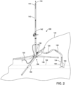
FIG. 2 is a top perspective view of the purging device ofFIG. 1 shown in use; -
FIG. 3 is a top perspective view of a testing port and a control valve of the purging device ofFIG. 1 ; -
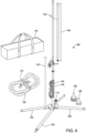
FIG. 4 is a top perspective view of a gas purging kit, according to an embodiment of the present disclosure; and -
FIG. 5 is a method of using a gas purging kit, according to an embodiment of the present disclosure. - The following description of technology is merely exemplary in nature of the subject matter, manufacture and use of one or more inventions, and is not intended to limit the scope, application, or uses of any specific invention claimed in this application or in such other applications as may be filed claiming priority to this application, or patents issuing therefrom. Regarding methods disclosed, the order of the steps presented is exemplary in nature, and thus, the order of the steps can be different in various embodiments, including where certain steps can be simultaneously performed, unless expressly stated otherwise. "A" and "an" as used herein indicate "at least one" of the item is present; a plurality of such items may be present, when possible. Except where otherwise expressly indicated, all numerical quantities in this description are to be understood as modified by the word "about" and all geometric and spatial descriptors are to be understood as modified by the word "substantially" in describing the broadest scope of the technology. "About" when applied to numerical values indicates that the calculation or the measurement allows some slight imprecision in the value (with some approach to exactness in the value; approximately or reasonably close to the value; nearly). If, for some reason, the imprecision provided by "about" and/or "substantially" is not otherwise understood in the art with this ordinary meaning, then "about" and/or "substantially" as used herein indicates at least variations that may arise from ordinary methods of measuring or using such parameters.
- Although the open-ended term "comprising," as a synonym of non-restrictive terms such as including, containing, or having, is used herein to describe and claim embodiments of the present technology, embodiments may alternatively be described using more limiting terms such as "consisting of' or "consisting essentially of." Thus, for any given embodiment reciting materials, components, or process steps, the present technology also specifically includes embodiments consisting of, or consisting essentially of, such materials, components, or process steps excluding additional materials, components or processes (for consisting of) and excluding additional materials, components or processes affecting the significant properties of the embodiment (for consisting essentially of), even though such additional materials, components or processes are not explicitly recited in this application. For example, recitation of a composition or process reciting elements A, B and C specifically envisions embodiments consisting of, and consisting essentially of, A, B and C, excluding an element D that may be recited in the art, even though element D is not explicitly described as being excluded herein.
- When an element or layer is referred to as being "on," "engaged to," "connected to," or "coupled to" another element or layer, it may be directly on, engaged, connected or coupled to the other element or layer, or intervening elements or layers may be present. In contrast, when an element is referred to as being "directly on," "directly engaged to," "directly connected to" or "directly coupled to" another element or layer, there may be no intervening elements or layers present. Other words used to describe the relationship between elements should be interpreted in a like fashion (e.g., "between" versus "directly between," "adjacent" versus "directly adjacent," etc.). As used herein, the term "and/or" includes any and all combinations of one or more of the associated listed items.
- Although the terms first, second, third, etc. may be used herein to describe various elements, components, regions, layers and/or sections, these elements, components, regions, layers and/or sections should not be limited by these terms. These terms may be only used to distinguish one element, component, region, layer or section from another region, layer or section. Terms such as "first," "second," and other numerical terms when used herein do not imply a sequence or order unless clearly indicated by the context. Thus, a first element, component, region, layer or section discussed below could be termed a second element, component, region, layer or section without departing from the teachings of the example embodiments.
- Spatially relative terms, such as "inner," "outer," "beneath," "below," "lower," "above," "upper," and the like, may be used herein for ease of description to describe one element or feature's relationship to another element(s) or feature(s) as illustrated in the figures. Spatially relative terms may be intended to encompass different orientations of the device in use or operation in addition to the orientation depicted in the figures. For example, if the device in the figures is turned over, elements described as "below" or "beneath" other elements or features would then be oriented "above" the other elements or features. Thus, the example term "below" can encompass both an orientation of above and below. The device may be otherwise oriented (rotated 90 degrees or at other orientations) and the spatially relative descriptors used herein interpreted accordingly.
- With reference to
FIGS. 1-3 , apurging device 100 is shown. Thepurging device 100 may be configured to connect to agas system 102 allowing a technician to purgegas 104 from thegas system 102. As one non-limiting example, thegas system 102 may be a natural gas pipeline. Thepurging device 100, according to certain embodiments, may include amain body 106, abase 108, atesting port 110, and acontrol valve 112. - The
main body 106 may be a conduit or other enclosed channel configured to receivegas 104 through aninlet 114 disposed at afirst end 116 of themain body 106 and expel gas through anoutlet 118 disposed at asecond end 120 of themain body 106. Themain body 106 may have any desirable shape, length, diameter, and thickness, as determined by one of skill in the art. As non-limiting examples, in certain embodiments, themain body 106 may have a diameter of three-quarters of an inch, one inch, or two inches. - Any material or combination of materials such as metal, plastic, composite, and wood may be used to fabricate the
main body 106 of thepurging device 100. It should be appreciated that a skilled artisan may employ materials and dimensions that match particular industrial standards and regulations, as needed. Themain body 106 may have aheight 122 that is fixed or adjustable. In certain more particular embodiments, themain body 106 may be fabricated using steel and capable of withstanding line pressure up to 125 PSI. In certain more particular embodiments, themain body 106 may be made using schedule 40 piping. Advantageously, thepurging device 100 is lightweight, easy to transport, and inexpensive to manufacture. In another more particular embodiment, themain body 106 may be fabricated using steel and capable of withstanding line pressure greater than 125 PSI. - The
inlet 114 may be configured to receivegas 104, such as air or natural gas, from thegas system 102. Theinlet 114 may be integral with themain body 106 of thepurging device 100 or may be permanently or removably connected to themain body 106, as determined by one of skill in the art. According to certain more particular embodiments, theinlet 114 may be disposed adjacent to aground surface 124 to facilitate an easy, safe connection with thegas system 102. However, a skilled artisan may position theinlet 114 anywhere on or along themain body 106 of thepurging device 100 between thefirst end 116 and theoutlet 118. - According to certain embodiments, the
inlet 114 may be an opening defined by thefirst end 116 of the main body 106 (not shown). Alternatively, in certain more particular embodiments, theinlet 114 may extend outwardly from asidewall 126 of themain body 106, as shown inFIGS. 1-4 . As one non-limiting example, theinlet 114 may be a conduit extending outwardly at a 90-degree angle from thesidewall 126 of themain body 106 adjacent thefirst end 116 of themain body 106. Any material or combination of materials such as metal, plastic, composite, and wood may be used to fabricate theinlet 114. In certain more particular embodiments, steel may be used to form theinlet 114 or a portion of theinlet 114. - In certain embodiments, as shown in
FIG. 2 , thepurging device 100 may include aflexible hose 128 adapted to connect to theinlet 114 and be in fluid communication with thepurging device 100 and thegas system 102. Theflexible hose 128 may be made from any durable material capable of withstanding pressure from thegas system 102. As non-limiting examples, nylon, polyurethane, polyethylene, PVC, and synthetic or natural rubber may be used. A skilled artisan may select any suitable length and diameter for theflexible hose 128. In one more particular embodiment, theflexible hose 128 may be 12 feet in length. It should be appreciated that a skilled artisan may achieve fluid communication between the purgingdevice 100 and thegas system 102 by employing any number of components and methods, within the scope of this disclosure. - The
flexible hose 128 may be integral with or permanently or removably connected to theinlet 114 at afirst end 130 of theflexible hose 128 using any suitablepurge connecting means 132. As non-limiting examples, theflexible hose 128 may be removably connected to theinlet 114 using a threaded connection, a snap fit, a friction fit, or a quick connect fitting. Theflexible hose 128 may be configured to removably connect to thegas system 102 at asecond end 134 of theflexible hose 128 using one or moregas connecting means 136. In certain embodiments, theflexible hose 128 may include a variety of interchangeable gas connecting means 136 for connecting thesecond end 134 of theflexible hose 128 to a variety ofgas systems 102, as needed. Advantageously, theflexible hose 128 allows the technician to purgegas 104 at a safe distance from thegas system 102. Additionally, theflexible hose 128 is lightweight and flexible for easy storage and transport and adaptable in variable settings and on variable terrain. - The
outlet 118 may be configured to expelgas 104 into an external environment. In one non-limiting example, theoutlet 118 may direct air from thegas system 102 to achieve a higher natural gas level in thegas system 102. According to certain more particular embodiments, theoutlet 118 may be positioned to expel gas upwardly away from theground surface 124. However, a skilled artisan may position theoutlet 118 anywhere on themain body 106 between theinlet 114 and thesecond end 120 of themain body 106. - In certain embodiments, the
outlet 118 may be integral with themain body 106 of thepurging device 100 or may be permanently or removably connected to themain body 106, as determined by one of skill in the art. According to certain more particular embodiments, theoutlet 118 may be defined by anopening 138 disposed at thesecond end 120 of themain body 106. Alternatively, in certain embodiments, theoutlet 118 may extend outwardly from thesidewall 126 of the main body 106 (not shown). Any material or combination of materials such as metal, plastic, composite, steel, and wood may be used to form or define theoutlet 118. - With renewed reference to
FIG. 2 , theoutlet 118 may be configured to receive at least oneextender 140 according to certain embodiments. Theextender 140 may be configured to increase theheight 122 of themain body 106 to militate againstgas 104 escaping from theoutlet 118 and contacting the technician or creating other hazardous conditions. Theextender 140, in one non-limiting example, may be a conduit or other enclosed channel configured to receive thegas 104 from thesecond end 120 of themain body 106 at afirst end 142 of theextender 140 and expel thegas 104 from asecond end 144 of theextender 140 positioned at a distance from thepurging device 100 and thegas system 102. Theextender 140 may be removably connected to theoutlet 118 of themain body 106 using a threaded connection, a snap fit, a friction fit, or a quick connect fitting, as non-limiting examples. - The
extender 140 may have any desired shape, length, diameter, and thickness, as determined by one of skill in the art. Theextender 140 may have aheight 146 that is fixed or adjustable. Any material or combination of materials such as metal, plastic, composite, and wood may be used to fabricate theextender 140. It should be appreciated that a skilled artisan may employ materials and dimensions that match particular industrial standards and regulations, as needed. In certain more particular embodiments, theextender 140 may be fabricated using aluminum. In certain more particular embodiments, theheight 122 of themain body 106 combined with theheight 146 of theextender 140 may equal one of seven feet and ten feet, as non-limiting examples. Advantageously, theextender 140 allows the technician to safely purgegas 104 at a customizable height above ground to prevent dangerous conditions, protect the technician and any other workers nearby, and meet applicable industry and regulatory standards. - The
main body 106 of thepurging device 100 may include additional features such as a securingelement 148, as one non-limiting example. The securingelement 148 may be integral with themain body 106 or permanently or removably connected to themain body 106. The securingelement 148 may be configured to connect to a strap or other tie-down means (not shown). The strap or other tie-down means may be configured to be connected to theground surface 124 and used to secure and stabilize thepurging device 100 with respect to theground surface 124. In one more particular example, a plurality of securingelements 148 may extend outwardly from thesidewall 126 of themain body 106. Each securingelement 148 may be adapted to receive a strap, rope, or other tie-down means adapted to connect to the securingelements 148 and to theground surface 124. Any suitable material and configuration may be used to form the securingelement 148. It should be appreciated that a skilled artisan may further stabilize thepurging device 100 relative to theground surface 124 by employing any number of components and methods, within the scope of this disclosure. - A grounding rod and
cable 150 may be permanently or removably connected to themain body 106 of thepurging device 100 and configured to provide a low resistance electrical path to theground surface 124, according to certain embodiments. A skilled artisan may use any suitable grounding rod andcable 150, as desired. Themain body 106 may include one or more attachment means 152 for securing and storing the grounding rod andcable 150 with thepurging device 100 when the grounding rod andcable 150 are not in use. Advantageously, the grounding rod andcable 150 may reroute unwanted static electricity to theground surface 124 to militate againstgas 104 being ignited from the static electricity. - The base 108 may be integral with the
first end 116 of themain body 106 of thepurging device 100 or may be permanently or removably connected to thefirst end 116 of themain body 106 and may be configured to stabilize thepurging device 100 during use. Any suitable base connecting means 154 may be employed. As non-limiting examples, thebase 108 may be connected to themain body 106 using a plurality of threading connectors, thumb screws, friction fit, snap fit, or any other suitable means, as determined by one of skill in the art. The base 108 may be fabricated using any durable material or combination of materials such as metal, plastic, wood, and composite, as non-limiting examples. A skilled artisan may select any desirable shape and size for thebase 108. - According to one more particular embodiment, the
base 108 may include a plurality oflegs 156 extending outwardly from thefirst end 116 of themain body 106 of thepurging device 100 and configured to stabilize thepurging device 100 with respect to theground surface 124. Eachleg 156 may be independently extendable, collapsible, and otherwise adjustable in both length and position relative to theground surface 124 and themain body 106 of thepurging device 100. In one more particular embodiment, eachleg 156 may be adjustable with respect to the angle at which theleg 156 extends outwardly from themain body 106 of thepurging device 100. According to certain more particular embodiments, eachleg 156 may have a predetermined set of angled positions relative to themain body 106 of thepurging device 100. - Advantageously, the
adjustable legs 156 and easy-to-connect base 108 may allow thepurging device 100 to be assembled and stabilized efficiently on uneven,rough ground surface 124. Additionally, theadjustable legs 156 may be easily collapsed and compactly stored adjacent themain body 106 of thepurging device 100, as needed. The added stability added by theadjustable base 108 militates against hazardous conditions that may result from thepurging device 100 falling over. - With reference to
FIG. 3 , thetesting port 110 may include afirst end 158 that is integrally formed with or permanently or removably connected to thesidewall 126 of themain body 106. Thetesting port 110 may be in fluid communication with themain body 106 of thepurging device 100. Thetesting port 110 may have any desired shape, length, diameter, and thickness, as determined by one of skill in the art. Any material or combination of materials such as metal, plastic, composite, and wood, as non-limiting examples, may be used to form thetesting port 110. In certain embodiments, thetesting port 110 may be fabricated using a material that is capable of withstanding line pressure up to or exceeding 125 PSI. Additionally, according to certain embodiments, a size, position, orientation, and configuration of thetesting port 110 relative to themain body 106 of thepurging device 100 may be configured to militate against the gas creating a Venturi effect. - A
testing valve 160 may be integrally formed in or connected to thetesting port 110 device and configured to be selectively engaged by the technician to allow thegas 104 to flow out of asecond end 162 of thetesting port 110. More specifically, the technician may selectively allowgas 104 to flow out of thesecond end 162 of thetesting port 110 when thetesting valve 160 is in an open position and preventgas 104 from flowing out of thesecond end 162 of thetesting port 110 when thetesting valve 160 is in a closed position. Ahandle 164 can be used to alternate thetesting valve 160 between the open position and the closed position. Anysuitable testing valve 160 capable of permitting and preventinggas 104 flow from thesecond end 162 of thetesting port 110 may be used, such as a ball valve, gate valve, globe valve, or butterfly valve, as non-limiting examples. - In a more particular embodiment, the
testing port 110 may be a 90-degree shoulder fitting including thetesting valve 160, as shown inFIG. 3 . In certain embodiments, the 90-degree shoulder fitting may be connected to themain body 106 using a three-eighths inch nipple welded to themain body 106, as one non-limiting example. In another more particular embodiment, thetesting port 110 may be positioned between theinlet 114 of themain body 106 and theoutlet 118 of themain body 106. Thetesting port 110 may militate againstgas 104 creating a Venturi effect. It should be appreciated that one skilled in the art may employ different methods and structures for including atesting port 110 that is in fluid communication with themain body 106 of thepurging device 100. - Advantageously, the
testing port 110 allows the technician to measure the level ofgas 104 within thegas system 102 while thegas 104 is flowing from thegas system 102 through thepurging device 100. Additionally, in certain embodiments, thetesting port 110 is configured to militate againstgas 104 creating a Venturi effect. - The
control valve 112 may be permanently or removably positioned within or along themain body 106 of thepurging device 100 and configured to allow the technician to selectively preventgas 104 from flowing out of theoutlet 118 of themain body 106 using ahandle 165 or other means extending outwardly from themain body 106 of thepurging device 100. Any suitable valve type may be employed such as a ball valve, gate valve, globe valve, or butterfly valve, as non-limiting examples. In certain embodiments, thecontrol valve 112 may be positioned within or along themain body 106 at a location that does not require the technician to bend over to access thecontrol valve 112. In one more particular embodiment, thecontrol valve 112 may be positioned between theinlet 114 of thepurging device 100 and thetesting port 110. - It should be appreciated that a person skilled in the art may select any
suitable control valve 112 and may adjust the position of thecontrol valve 112 as required, within the scope of this disclosure. It should be further appreciated that a skilled artisan may employ any suitable structural components and methods for controlling the flow ofgas 104 through themain body 106 of thepurging device 100, within the scope of this disclosure. Advantageously, thecontrol valve 112 allows the technician to selectively allowgas 104 to be expelled from thepurging device 100 or to preventgas 104 from being expelled from thepurging device 100. - In another embodiment of the present disclosure, a
gas purging kit 166 is used to purgeunwanted gas 104 from thegas system 102 or other gas source, as shown inFIG. 4 . Thegas purging kit 166 includes thepurging device 100 according to various embodiments of the present disclosure, at least oneflexible hose 128, at least oneextender 140, one ormore safety cones 168, and a carryingcase 170. In certain embodiments, thegas purging kit 166 may include tie-down straps or other securing means (not shown) and hook and loop, elastic, orother organizing connectors 172 for organizing cords, straps, and hoses. Additionally, safety signage, additional testing equipment, replacement parts, and various fittings and connectors (not shown) may be included, as determined by one of skill in the art. - Advantageously, the
gas purging kit 166 may be used to purgegas 104 or air from thegas system 102, while militating against associated hazards. For example, thesafety cones 168 may be placed around thepurging device 100 and adjacent theflexible hose 128 to visually point out a possible tripping hazard associated with thepurging device 100. Additionally, theflexible hose 128 allows the technician to maintain a purge point at a safe operating distance. Likewise, the technician may adjust the overall height of thepurging device 100 in order to meet safety standards and follow company specific procedures using one ormore extenders 140, as needed. In certain more particular embodiments, thegas purging kit 166 may includeflexible hoses 128 of variable length as well asextenders 140 of variable height thereby allowing the technician to select and appropriate distance and height from thegas system 102. - The light weight, collapsible components of the
gas purging kit 166 including themain body 106, thebase 108, theflexible hose 128, and theextender 140 are easy to store and transport using theconvenient carrying case 170. Advantageously, each of thebase 108, theflexible hose 128, and theextender 140 may be collapsed and placed in a compact position alongside themain body 106 inside the carryingcase 170. The lightweight, thin materials such as aluminum and schedule 40 piping, as non-limiting materials, allow the technician to transport thegas purging kit 166 with ease. Likewise, the easy-to-usepurge connecting means 132 and gas connecting means 136 allow for efficient set up and tear down of thegas purging kit 166. - In yet another embodiment of the present disclosure, with reference to
FIG. 5 , amethod 400 of using thegas purging kit 166, is shown. Themethod 400 may include afirst step 402 of providing thegas purging kit 166. Themethod 400 may further include asecond step 404 of identifying thegas system 102 for purging. Athird step 406 may include assembling thepurging device 100. As one non-limiting example, assembling thepurging device 100 may include connecting themain body 106 to thebase 108, adjusting thelegs 156 of thebase 108, selecting one or more of theflexible hose 128 and theextender 140 for use in combination with thepurging device 100, securing tie-down straps to the securingelements 148 and to theground surface 124, and securing the rod andcable 150 to theground surface 124, as non-limiting examples. Anadditional step 408 may include connecting theinlet 114 of thepurging device 100 to thegas system 102 using theflexible hose 128 such that thepurging device 100 and thegas system 102 are in fluid communication with one another. Afinal step 410 may include purging thegas 104 from thegas system 102. - It should be appreciated that additional steps may be included, as determined by one of skill in the art. As non-limiting examples, various steps relating to the setup of the
purging device 100, adjustment of various components such as the plurality oflegs 156, safety precautions, testing, and disassembling of thegas purging kit 166 may be included. Themethod 400 for using thegas purging kit 166 may also include repeating or omitting various steps, as required. Advantageously, thepurging device 100, thegas purging kit 166, and themethod 400 of using thegas purging kit 166 may be used in a multitude of settings and may be customized, as determined by a skilled artisan. - Example embodiments are provided so that this disclosure will be through and fully convey the scope to those who are skilled in the art. Numerous specific details are set forth such as examples of specific components, devices, and methods, to provide a thorough understanding of embodiments of the present disclosure. It will be apparent to those skilled in the art that specific details need not be employed, that example embodiments may be embodied in many different forms, and that neither should be construed to limit the scope of the disclosure. In some example embodiments, well-known processes, well-known device structures, and well-known technologies are not described in detail. Equivalent changes, modifications and variations of some embodiments, materials, components and methods may be made within the scope of the present technology, with substantially similar results.
Claims (15)
- A purging device, comprising:a main body having an inlet disposed at a first end of the main body and an outlet disposed at a second end of the main body;a base positioned adjacent the first end of the main body, the base including a plurality of legs, and a length of each leg of the plurality of legs is independently adjustable;a testing port disposed along the main body of the purging device;a control valve disposed between the inlet of the main body and the outlet of the main body; anda threaded port disposed below the control valve on the main body.
- The purging device of Claim 1, wherein the main body is fabricated from schedule 40 piping.
- The purging device of Claim 1 or Claim 2, further comprising a flexible hose adapted to connect to the inlet of the main body and provide fluid communication between the purging device and a gas system.
- The purging device of any of Claims 1 to 3, wherein an extender is adapted to connect to the outlet of the main body.
- The purging device of Claim 4, wherein the extender is fabricated from aluminum.
- The purging device of Claim 4 or Claim 5, wherein a height of the main body combined with a height of the extender is between seven feet and ten feet.
- The purging device of any of Claims 1 to 6, wherein the main body has a plurality of securing elements extending outwardly from a sidewall of the main body, the securing elements configured to secure the purging device to a ground surface.
- The purging device of any of Claims 1 to 7, wherein the purging device includes a grounding rod and cable connected to the main body.
- The purging device of any of Claims 1 to 8, wherein the base is removably connected to the first end of main body.
- The purging device of any of Claims 1 to 9, wherein each leg of the plurality of legs extends outwardly from the main body of the purging device, and wherein an angle of each leg relative to the main body of the purging device is adjustable.
- The purging device of any of Claims 1 to 10, wherein the testing port extends outwardly from a sidewall of the main body, the testing port in fluid communication with the main body.
- The purging device of any of Claims 1 to 11, wherein the testing port includes a 90-degree shoulder fitting and is adapted to militate against a gas from a gas system creating a Venturi effect.
- The purging device of any of Claims 1 to 12, wherein the main body has a height that is adjustable.
- The purging device of any of Claims 1 to 13, wherein a testing valve is integrally formed in or connected to the testing port.
- A gas purging kit, comprising:a purging device including a main body having an inlet disposed at a first end of the main body and an outlet disposed at a second end of the main body, a base positioned adjacent the first end of the main body the base including a plurality of legs, and a length of each leg of the plurality of legs is independently adjustable, a testing port disposed along the main body of the purging device, a control valve disposed between the inlet of the main body and the outlet of the main body, and a threaded port disposed below the control valve on the main body;a flexible hose adapted to connect to the inlet of the main body;an extender adapted to connect to the outlet of the main body;at least one safety cone; anda carrying case.
Applications Claiming Priority (1)
| Application Number | Priority Date | Filing Date | Title |
|---|---|---|---|
| US17/846,233 US12410878B2 (en) | 2021-06-28 | 2022-06-22 | Purge stand |
Publications (3)
| Publication Number | Publication Date |
|---|---|
| EP4296560A1 true EP4296560A1 (en) | 2023-12-27 |
| EP4296560C0 EP4296560C0 (en) | 2026-02-04 |
| EP4296560B1 EP4296560B1 (en) | 2026-02-04 |
Family
ID=86942812
Family Applications (1)
| Application Number | Title | Priority Date | Filing Date |
|---|---|---|---|
| EP23180773.6A Active EP4296560B1 (en) | 2022-06-22 | 2023-06-21 | Purge stand |
Country Status (1)
| Country | Link |
|---|---|
| EP (1) | EP4296560B1 (en) |
Citations (4)
| Publication number | Priority date | Publication date | Assignee | Title |
|---|---|---|---|---|
| US6056004A (en) | 1999-07-02 | 2000-05-02 | Agnew; A. Patrick | Portable compression system for pipeline purging |
| US20120308940A1 (en) * | 2011-06-02 | 2012-12-06 | Caso Vincent J | Natural gas purge burner and associated systems and methods |
| GB2508823A (en) * | 2012-12-11 | 2014-06-18 | Express Pipe Laying And Repairs Ltd | Gas venting conduit having an outlet at a pre-determinable height and an associated stand |
| US20200340627A1 (en) * | 2019-04-24 | 2020-10-29 | Joshua D. Ott | Combustible gas purge system |
-
2023
- 2023-06-21 EP EP23180773.6A patent/EP4296560B1/en active Active
Patent Citations (4)
| Publication number | Priority date | Publication date | Assignee | Title |
|---|---|---|---|---|
| US6056004A (en) | 1999-07-02 | 2000-05-02 | Agnew; A. Patrick | Portable compression system for pipeline purging |
| US20120308940A1 (en) * | 2011-06-02 | 2012-12-06 | Caso Vincent J | Natural gas purge burner and associated systems and methods |
| GB2508823A (en) * | 2012-12-11 | 2014-06-18 | Express Pipe Laying And Repairs Ltd | Gas venting conduit having an outlet at a pre-determinable height and an associated stand |
| US20200340627A1 (en) * | 2019-04-24 | 2020-10-29 | Joshua D. Ott | Combustible gas purge system |
Also Published As
| Publication number | Publication date |
|---|---|
| EP4296560C0 (en) | 2026-02-04 |
| EP4296560B1 (en) | 2026-02-04 |
Similar Documents
| Publication | Publication Date | Title |
|---|---|---|
| US12053656B2 (en) | Fire-fighting control system | |
| US20070062590A1 (en) | Valve for a fire hose line | |
| CN105431793B (en) | Control equipment for gas pressure adjuster | |
| US11904194B2 (en) | Stream straightener | |
| US20170114961A1 (en) | Valve unit for gas container with a pressure-indicating or autonomy-indication device near the top | |
| EP4296560B1 (en) | Purge stand | |
| AU2023203926B2 (en) | Purge stand | |
| US20190192892A1 (en) | Inert Gas Remote Driver Liquid Fire Suppression Systems | |
| US20210396411A1 (en) | Safety shutdown systems and methods for lng, crude oil refineries, petrochemical plants, and other facilities | |
| AU2019217365A1 (en) | Breathable gas and water hose apparatus | |
| US20120308940A1 (en) | Natural gas purge burner and associated systems and methods | |
| KR20180000859U (en) | Manual controlling apparatus of pneumatic remote automatic valve in fire fighting water pipe control system of ship engine room | |
| US7213734B2 (en) | Pneumatic tool drive system | |
| IT201600098296A1 (en) | FURNISHED EQUIPMENT FOR THE SUPPLY OF GASEOUS BLENDS ENTRY TO A COMPRESSOR IN HIGH PRESSURE | |
| CN207073657U (en) | A kind of Gas Stations of multi-purpose ring flange and its composition are vented temporarily and nitrogen injection device | |
| Semassou et al. | Study, dimensioning and realization of a fire fighting [J] | |
| GB2508823A (en) | Gas venting conduit having an outlet at a pre-determinable height and an associated stand | |
| EP0884573A2 (en) | Fluid detection device | |
| US11896861B2 (en) | Apparatus for diverting fire protection fluid discharged from deluge nozzles | |
| WO2020117477A1 (en) | Mobile air supply cart | |
| CA3090374C (en) | Breathable gas and water hose apparatus | |
| GB2397867A (en) | Hose shut-off valve | |
| US20150089769A1 (en) | Cylinder safety system | |
| WO2024003710A1 (en) | Demand valve for an oxy-fuel welding and cutting system | |
| CA3028430A1 (en) | Inert gas remote driver liquid fire suppression systems |
Legal Events
| Date | Code | Title | Description |
|---|---|---|---|
| PUAI | Public reference made under article 153(3) epc to a published international application that has entered the european phase |
Free format text: ORIGINAL CODE: 0009012 |
|
| STAA | Information on the status of an ep patent application or granted ep patent |
Free format text: STATUS: THE APPLICATION HAS BEEN PUBLISHED |
|
| AK | Designated contracting states |
Kind code of ref document: A1 Designated state(s): AL AT BE BG CH CY CZ DE DK EE ES FI FR GB GR HR HU IE IS IT LI LT LU LV MC ME MK MT NL NO PL PT RO RS SE SI SK SM TR |
|
| STAA | Information on the status of an ep patent application or granted ep patent |
Free format text: STATUS: REQUEST FOR EXAMINATION WAS MADE |
|
| 17P | Request for examination filed |
Effective date: 20240627 |
|
| RBV | Designated contracting states (corrected) |
Designated state(s): AL AT BE BG CH CY CZ DE DK EE ES FI FR GB GR HR HU IE IS IT LI LT LU LV MC ME MK MT NL NO PL PT RO RS SE SI SK SM TR |
|
| GRAP | Despatch of communication of intention to grant a patent |
Free format text: ORIGINAL CODE: EPIDOSNIGR1 |
|
| STAA | Information on the status of an ep patent application or granted ep patent |
Free format text: STATUS: GRANT OF PATENT IS INTENDED |
|
| INTG | Intention to grant announced |
Effective date: 20250523 |
|
| GRAS | Grant fee paid |
Free format text: ORIGINAL CODE: EPIDOSNIGR3 |
|
| GRAA | (expected) grant |
Free format text: ORIGINAL CODE: 0009210 |
|
| STAA | Information on the status of an ep patent application or granted ep patent |
Free format text: STATUS: THE PATENT HAS BEEN GRANTED |
|
| AK | Designated contracting states |
Kind code of ref document: B1 Designated state(s): AL AT BE BG CH CY CZ DE DK EE ES FI FR GB GR HR HU IE IS IT LI LT LU LV MC ME MK MT NL NO PL PT RO RS SE SI SK SM TR |
|
| REG | Reference to a national code |
Ref country code: CH Ref legal event code: F10 Free format text: ST27 STATUS EVENT CODE: U-0-0-F10-F00 (AS PROVIDED BY THE NATIONAL OFFICE) Effective date: 20260204 Ref country code: GB Ref legal event code: FG4D |
|
| REG | Reference to a national code |
Ref country code: IE Ref legal event code: FG4D |
|
| REG | Reference to a national code |
Ref country code: DE Ref legal event code: R096 Ref document number: 602023011487 Country of ref document: DE |
|
| U01 | Request for unitary effect filed |
Effective date: 20260304 |
|
| U07 | Unitary effect registered |
Designated state(s): AT BE BG DE DK EE FI FR IT LT LU LV MT NL PT RO SE SI Effective date: 20260310 |
|
| PG25 | Lapsed in a contracting state [announced via postgrant information from national office to epo] |
Ref country code: RS Free format text: LAPSE BECAUSE OF FAILURE TO SUBMIT A TRANSLATION OF THE DESCRIPTION OR TO PAY THE FEE WITHIN THE PRESCRIBED TIME-LIMIT Effective date: 20260504 |
|
| PG25 | Lapsed in a contracting state [announced via postgrant information from national office to epo] |
Ref country code: ES Free format text: LAPSE BECAUSE OF FAILURE TO SUBMIT A TRANSLATION OF THE DESCRIPTION OR TO PAY THE FEE WITHIN THE PRESCRIBED TIME-LIMIT Effective date: 20260204 |
|
| PG25 | Lapsed in a contracting state [announced via postgrant information from national office to epo] |
Ref country code: PL Free format text: LAPSE BECAUSE OF FAILURE TO SUBMIT A TRANSLATION OF THE DESCRIPTION OR TO PAY THE FEE WITHIN THE PRESCRIBED TIME-LIMIT Effective date: 20260204 |
|
| PG25 | Lapsed in a contracting state [announced via postgrant information from national office to epo] |
Ref country code: GR Free format text: LAPSE BECAUSE OF FAILURE TO SUBMIT A TRANSLATION OF THE DESCRIPTION OR TO PAY THE FEE WITHIN THE PRESCRIBED TIME-LIMIT Effective date: 20260505 |
|
| PG25 | Lapsed in a contracting state [announced via postgrant information from national office to epo] |
Ref country code: NO Free format text: LAPSE BECAUSE OF FAILURE TO SUBMIT A TRANSLATION OF THE DESCRIPTION OR TO PAY THE FEE WITHIN THE PRESCRIBED TIME-LIMIT Effective date: 20260504 |
|
| PG25 | Lapsed in a contracting state [announced via postgrant information from national office to epo] |
Ref country code: HR Free format text: LAPSE BECAUSE OF FAILURE TO SUBMIT A TRANSLATION OF THE DESCRIPTION OR TO PAY THE FEE WITHIN THE PRESCRIBED TIME-LIMIT Effective date: 20260204 |
|
| PG25 | Lapsed in a contracting state [announced via postgrant information from national office to epo] |
Ref country code: IS Free format text: LAPSE BECAUSE OF FAILURE TO SUBMIT A TRANSLATION OF THE DESCRIPTION OR TO PAY THE FEE WITHIN THE PRESCRIBED TIME-LIMIT Effective date: 20260604 |
|
| U20 | Renewal fee for the european patent with unitary effect paid |
Year of fee payment: 4 Effective date: 20260625 |