EP4296558A1 - Method for producing a composite cylindrical tank and composite tank produced by this method - Google Patents
Method for producing a composite cylindrical tank and composite tank produced by this method Download PDFInfo
- Publication number
- EP4296558A1 EP4296558A1 EP22305909.8A EP22305909A EP4296558A1 EP 4296558 A1 EP4296558 A1 EP 4296558A1 EP 22305909 A EP22305909 A EP 22305909A EP 4296558 A1 EP4296558 A1 EP 4296558A1
- Authority
- EP
- European Patent Office
- Prior art keywords
- composite
- tool kit
- fibre
- breather
- tank
- Prior art date
- Legal status (The legal status is an assumption and is not a legal conclusion. Google has not performed a legal analysis and makes no representation as to the accuracy of the status listed.)
- Granted
Links
Images


Classifications
-
- F—MECHANICAL ENGINEERING; LIGHTING; HEATING; WEAPONS; BLASTING
- F17—STORING OR DISTRIBUTING GASES OR LIQUIDS
- F17C—VESSELS FOR CONTAINING OR STORING COMPRESSED, LIQUEFIED OR SOLIDIFIED GASES; FIXED-CAPACITY GAS-HOLDERS; FILLING VESSELS WITH, OR DISCHARGING FROM VESSELS, COMPRESSED, LIQUEFIED, OR SOLIDIFIED GASES
- F17C1/00—Pressure vessels, e.g. gas cylinder, gas tank, replaceable cartridge
- F17C1/02—Pressure vessels, e.g. gas cylinder, gas tank, replaceable cartridge involving reinforcing arrangements
- F17C1/04—Protecting sheathings
- F17C1/06—Protecting sheathings built-up from wound-on bands or filamentary material, e.g. wires
-
- B—PERFORMING OPERATIONS; TRANSPORTING
- B29—WORKING OF PLASTICS; WORKING OF SUBSTANCES IN A PLASTIC STATE IN GENERAL
- B29C—SHAPING OR JOINING OF PLASTICS; SHAPING OF MATERIAL IN A PLASTIC STATE, NOT OTHERWISE PROVIDED FOR; AFTER-TREATMENT OF THE SHAPED PRODUCTS, e.g. REPAIRING
- B29C70/00—Shaping composites, i.e. plastics material comprising reinforcements, fillers or preformed parts, e.g. inserts
- B29C70/04—Shaping composites, i.e. plastics material comprising reinforcements, fillers or preformed parts, e.g. inserts comprising reinforcements only, e.g. self-reinforcing plastics
- B29C70/06—Fibrous reinforcements only
- B29C70/08—Fibrous reinforcements only comprising combinations of different forms of fibrous reinforcements incorporated in matrix material, forming one or more layers, and with or without non-reinforced layers
- B29C70/086—Fibrous reinforcements only comprising combinations of different forms of fibrous reinforcements incorporated in matrix material, forming one or more layers, and with or without non-reinforced layers and with one or more layers of pure plastics material, e.g. foam layers
-
- B—PERFORMING OPERATIONS; TRANSPORTING
- B29—WORKING OF PLASTICS; WORKING OF SUBSTANCES IN A PLASTIC STATE IN GENERAL
- B29C—SHAPING OR JOINING OF PLASTICS; SHAPING OF MATERIAL IN A PLASTIC STATE, NOT OTHERWISE PROVIDED FOR; AFTER-TREATMENT OF THE SHAPED PRODUCTS, e.g. REPAIRING
- B29C70/00—Shaping composites, i.e. plastics material comprising reinforcements, fillers or preformed parts, e.g. inserts
- B29C70/68—Shaping composites, i.e. plastics material comprising reinforcements, fillers or preformed parts, e.g. inserts by incorporating or moulding on preformed parts, e.g. inserts or layers, e.g. foam blocks
- B29C70/72—Encapsulating inserts having non-encapsulated projections, e.g. extremities or terminal portions of electrical components
-
- B—PERFORMING OPERATIONS; TRANSPORTING
- B29—WORKING OF PLASTICS; WORKING OF SUBSTANCES IN A PLASTIC STATE IN GENERAL
- B29C—SHAPING OR JOINING OF PLASTICS; SHAPING OF MATERIAL IN A PLASTIC STATE, NOT OTHERWISE PROVIDED FOR; AFTER-TREATMENT OF THE SHAPED PRODUCTS, e.g. REPAIRING
- B29C53/00—Shaping by bending, folding, twisting, straightening or flattening; Apparatus therefor
- B29C53/56—Winding and joining, e.g. winding spirally
- B29C53/58—Winding and joining, e.g. winding spirally helically
- B29C53/60—Winding and joining, e.g. winding spirally helically using internal forming surfaces, e.g. mandrels
- B29C53/602—Winding and joining, e.g. winding spirally helically using internal forming surfaces, e.g. mandrels for tubular articles having closed or nearly closed ends, e.g. vessels, tanks, containers
-
- B—PERFORMING OPERATIONS; TRANSPORTING
- B29—WORKING OF PLASTICS; WORKING OF SUBSTANCES IN A PLASTIC STATE IN GENERAL
- B29C—SHAPING OR JOINING OF PLASTICS; SHAPING OF MATERIAL IN A PLASTIC STATE, NOT OTHERWISE PROVIDED FOR; AFTER-TREATMENT OF THE SHAPED PRODUCTS, e.g. REPAIRING
- B29C53/00—Shaping by bending, folding, twisting, straightening or flattening; Apparatus therefor
- B29C53/80—Component parts, details or accessories; Auxiliary operations
- B29C53/82—Cores or mandrels
- B29C53/821—Mandrels especially adapted for winding and joining
- B29C53/824—Mandrels especially adapted for winding and joining collapsible, e.g. elastic or inflatable; with removable parts, e.g. for regular shaped, straight tubular articles
-
- B—PERFORMING OPERATIONS; TRANSPORTING
- B29—WORKING OF PLASTICS; WORKING OF SUBSTANCES IN A PLASTIC STATE IN GENERAL
- B29C—SHAPING OR JOINING OF PLASTICS; SHAPING OF MATERIAL IN A PLASTIC STATE, NOT OTHERWISE PROVIDED FOR; AFTER-TREATMENT OF THE SHAPED PRODUCTS, e.g. REPAIRING
- B29C63/00—Lining or sheathing, i.e. applying preformed layers or sheathings of plastics; Apparatus therefor
- B29C63/24—Lining or sheathing, i.e. applying preformed layers or sheathings of plastics; Apparatus therefor using threads
-
- B—PERFORMING OPERATIONS; TRANSPORTING
- B29—WORKING OF PLASTICS; WORKING OF SUBSTANCES IN A PLASTIC STATE IN GENERAL
- B29C—SHAPING OR JOINING OF PLASTICS; SHAPING OF MATERIAL IN A PLASTIC STATE, NOT OTHERWISE PROVIDED FOR; AFTER-TREATMENT OF THE SHAPED PRODUCTS, e.g. REPAIRING
- B29C63/00—Lining or sheathing, i.e. applying preformed layers or sheathings of plastics; Apparatus therefor
- B29C63/26—Lining or sheathing of internal surfaces
-
- B—PERFORMING OPERATIONS; TRANSPORTING
- B29—WORKING OF PLASTICS; WORKING OF SUBSTANCES IN A PLASTIC STATE IN GENERAL
- B29C—SHAPING OR JOINING OF PLASTICS; SHAPING OF MATERIAL IN A PLASTIC STATE, NOT OTHERWISE PROVIDED FOR; AFTER-TREATMENT OF THE SHAPED PRODUCTS, e.g. REPAIRING
- B29C70/00—Shaping composites, i.e. plastics material comprising reinforcements, fillers or preformed parts, e.g. inserts
- B29C70/04—Shaping composites, i.e. plastics material comprising reinforcements, fillers or preformed parts, e.g. inserts comprising reinforcements only, e.g. self-reinforcing plastics
- B29C70/06—Fibrous reinforcements only
- B29C70/08—Fibrous reinforcements only comprising combinations of different forms of fibrous reinforcements incorporated in matrix material, forming one or more layers, and with or without non-reinforced layers
-
- B—PERFORMING OPERATIONS; TRANSPORTING
- B29—WORKING OF PLASTICS; WORKING OF SUBSTANCES IN A PLASTIC STATE IN GENERAL
- B29C—SHAPING OR JOINING OF PLASTICS; SHAPING OF MATERIAL IN A PLASTIC STATE, NOT OTHERWISE PROVIDED FOR; AFTER-TREATMENT OF THE SHAPED PRODUCTS, e.g. REPAIRING
- B29C70/00—Shaping composites, i.e. plastics material comprising reinforcements, fillers or preformed parts, e.g. inserts
- B29C70/04—Shaping composites, i.e. plastics material comprising reinforcements, fillers or preformed parts, e.g. inserts comprising reinforcements only, e.g. self-reinforcing plastics
- B29C70/06—Fibrous reinforcements only
- B29C70/08—Fibrous reinforcements only comprising combinations of different forms of fibrous reinforcements incorporated in matrix material, forming one or more layers, and with or without non-reinforced layers
- B29C70/083—Combinations of continuous fibres or fibrous profiled structures oriented in one direction and reinforcements forming a two dimensional structure, e.g. mats
- B29C70/085—Combinations of continuous fibres or fibrous profiled structures oriented in one direction and reinforcements forming a two dimensional structure, e.g. mats the structure being deformed in a three dimensional configuration
-
- B—PERFORMING OPERATIONS; TRANSPORTING
- B29—WORKING OF PLASTICS; WORKING OF SUBSTANCES IN A PLASTIC STATE IN GENERAL
- B29C—SHAPING OR JOINING OF PLASTICS; SHAPING OF MATERIAL IN A PLASTIC STATE, NOT OTHERWISE PROVIDED FOR; AFTER-TREATMENT OF THE SHAPED PRODUCTS, e.g. REPAIRING
- B29C70/00—Shaping composites, i.e. plastics material comprising reinforcements, fillers or preformed parts, e.g. inserts
- B29C70/04—Shaping composites, i.e. plastics material comprising reinforcements, fillers or preformed parts, e.g. inserts comprising reinforcements only, e.g. self-reinforcing plastics
- B29C70/28—Shaping operations therefor
- B29C70/30—Shaping by lay-up, i.e. applying fibres, tape or broadsheet on a mould, former or core; Shaping by spray-up, i.e. spraying of fibres on a mould, former or core
- B29C70/32—Shaping by lay-up, i.e. applying fibres, tape or broadsheet on a mould, former or core; Shaping by spray-up, i.e. spraying of fibres on a mould, former or core on a rotating mould, former or core
-
- B—PERFORMING OPERATIONS; TRANSPORTING
- B29—WORKING OF PLASTICS; WORKING OF SUBSTANCES IN A PLASTIC STATE IN GENERAL
- B29C—SHAPING OR JOINING OF PLASTICS; SHAPING OF MATERIAL IN A PLASTIC STATE, NOT OTHERWISE PROVIDED FOR; AFTER-TREATMENT OF THE SHAPED PRODUCTS, e.g. REPAIRING
- B29C70/00—Shaping composites, i.e. plastics material comprising reinforcements, fillers or preformed parts, e.g. inserts
- B29C70/68—Shaping composites, i.e. plastics material comprising reinforcements, fillers or preformed parts, e.g. inserts by incorporating or moulding on preformed parts, e.g. inserts or layers, e.g. foam blocks
- B29C70/86—Incorporated in coherent impregnated reinforcing layers, e.g. by winding
-
- F—MECHANICAL ENGINEERING; LIGHTING; HEATING; WEAPONS; BLASTING
- F17—STORING OR DISTRIBUTING GASES OR LIQUIDS
- F17C—VESSELS FOR CONTAINING OR STORING COMPRESSED, LIQUEFIED OR SOLIDIFIED GASES; FIXED-CAPACITY GAS-HOLDERS; FILLING VESSELS WITH, OR DISCHARGING FROM VESSELS, COMPRESSED, LIQUEFIED, OR SOLIDIFIED GASES
- F17C1/00—Pressure vessels, e.g. gas cylinder, gas tank, replaceable cartridge
- F17C1/02—Pressure vessels, e.g. gas cylinder, gas tank, replaceable cartridge involving reinforcing arrangements
-
- F—MECHANICAL ENGINEERING; LIGHTING; HEATING; WEAPONS; BLASTING
- F17—STORING OR DISTRIBUTING GASES OR LIQUIDS
- F17C—VESSELS FOR CONTAINING OR STORING COMPRESSED, LIQUEFIED OR SOLIDIFIED GASES; FIXED-CAPACITY GAS-HOLDERS; FILLING VESSELS WITH, OR DISCHARGING FROM VESSELS, COMPRESSED, LIQUEFIED, OR SOLIDIFIED GASES
- F17C1/00—Pressure vessels, e.g. gas cylinder, gas tank, replaceable cartridge
- F17C1/16—Pressure vessels, e.g. gas cylinder, gas tank, replaceable cartridge constructed of plastics materials
-
- F—MECHANICAL ENGINEERING; LIGHTING; HEATING; WEAPONS; BLASTING
- F17—STORING OR DISTRIBUTING GASES OR LIQUIDS
- F17C—VESSELS FOR CONTAINING OR STORING COMPRESSED, LIQUEFIED OR SOLIDIFIED GASES; FIXED-CAPACITY GAS-HOLDERS; FILLING VESSELS WITH, OR DISCHARGING FROM VESSELS, COMPRESSED, LIQUEFIED, OR SOLIDIFIED GASES
- F17C13/00—Details of vessels or of the filling or discharging of vessels
-
- B—PERFORMING OPERATIONS; TRANSPORTING
- B29—WORKING OF PLASTICS; WORKING OF SUBSTANCES IN A PLASTIC STATE IN GENERAL
- B29C—SHAPING OR JOINING OF PLASTICS; SHAPING OF MATERIAL IN A PLASTIC STATE, NOT OTHERWISE PROVIDED FOR; AFTER-TREATMENT OF THE SHAPED PRODUCTS, e.g. REPAIRING
- B29C53/00—Shaping by bending, folding, twisting, straightening or flattening; Apparatus therefor
- B29C53/56—Winding and joining, e.g. winding spirally
- B29C53/58—Winding and joining, e.g. winding spirally helically
- B29C53/581—Winding and joining, e.g. winding spirally helically using sheets or strips consisting principally of plastics material
-
- B—PERFORMING OPERATIONS; TRANSPORTING
- B29—WORKING OF PLASTICS; WORKING OF SUBSTANCES IN A PLASTIC STATE IN GENERAL
- B29K—INDEXING SCHEME ASSOCIATED WITH SUBCLASSES B29B, B29C OR B29D, RELATING TO MOULDING MATERIALS OR TO MATERIALS FOR MOULDS, REINFORCEMENTS, FILLERS OR PREFORMED PARTS, e.g. INSERTS
- B29K2101/00—Use of unspecified macromolecular compounds as moulding material
- B29K2101/12—Thermoplastic materials
-
- B—PERFORMING OPERATIONS; TRANSPORTING
- B29—WORKING OF PLASTICS; WORKING OF SUBSTANCES IN A PLASTIC STATE IN GENERAL
- B29K—INDEXING SCHEME ASSOCIATED WITH SUBCLASSES B29B, B29C OR B29D, RELATING TO MOULDING MATERIALS OR TO MATERIALS FOR MOULDS, REINFORCEMENTS, FILLERS OR PREFORMED PARTS, e.g. INSERTS
- B29K2105/00—Condition, form or state of moulded material or of the material to be shaped
- B29K2105/06—Condition, form or state of moulded material or of the material to be shaped containing reinforcements, fillers or inserts
- B29K2105/12—Condition, form or state of moulded material or of the material to be shaped containing reinforcements, fillers or inserts of short lengths, e.g. chopped filaments, staple fibres or bristles
-
- B—PERFORMING OPERATIONS; TRANSPORTING
- B29—WORKING OF PLASTICS; WORKING OF SUBSTANCES IN A PLASTIC STATE IN GENERAL
- B29K—INDEXING SCHEME ASSOCIATED WITH SUBCLASSES B29B, B29C OR B29D, RELATING TO MOULDING MATERIALS OR TO MATERIALS FOR MOULDS, REINFORCEMENTS, FILLERS OR PREFORMED PARTS, e.g. INSERTS
- B29K2105/00—Condition, form or state of moulded material or of the material to be shaped
- B29K2105/24—Condition, form or state of moulded material or of the material to be shaped crosslinked or vulcanised
- B29K2105/243—Partially cured
-
- B—PERFORMING OPERATIONS; TRANSPORTING
- B29—WORKING OF PLASTICS; WORKING OF SUBSTANCES IN A PLASTIC STATE IN GENERAL
- B29K—INDEXING SCHEME ASSOCIATED WITH SUBCLASSES B29B, B29C OR B29D, RELATING TO MOULDING MATERIALS OR TO MATERIALS FOR MOULDS, REINFORCEMENTS, FILLERS OR PREFORMED PARTS, e.g. INSERTS
- B29K2307/00—Use of elements other than metals as reinforcement
- B29K2307/04—Carbon
-
- B—PERFORMING OPERATIONS; TRANSPORTING
- B29—WORKING OF PLASTICS; WORKING OF SUBSTANCES IN A PLASTIC STATE IN GENERAL
- B29K—INDEXING SCHEME ASSOCIATED WITH SUBCLASSES B29B, B29C OR B29D, RELATING TO MOULDING MATERIALS OR TO MATERIALS FOR MOULDS, REINFORCEMENTS, FILLERS OR PREFORMED PARTS, e.g. INSERTS
- B29K2309/00—Use of inorganic materials not provided for in groups B29K2303/00 - B29K2307/00, as reinforcement
- B29K2309/08—Glass
-
- B—PERFORMING OPERATIONS; TRANSPORTING
- B29—WORKING OF PLASTICS; WORKING OF SUBSTANCES IN A PLASTIC STATE IN GENERAL
- B29L—INDEXING SCHEME ASSOCIATED WITH SUBCLASS B29C, RELATING TO PARTICULAR ARTICLES
- B29L2031/00—Other particular articles
- B29L2031/712—Containers; Packaging elements or accessories, Packages
-
- B—PERFORMING OPERATIONS; TRANSPORTING
- B29—WORKING OF PLASTICS; WORKING OF SUBSTANCES IN A PLASTIC STATE IN GENERAL
- B29L—INDEXING SCHEME ASSOCIATED WITH SUBCLASS B29C, RELATING TO PARTICULAR ARTICLES
- B29L2031/00—Other particular articles
- B29L2031/712—Containers; Packaging elements or accessories, Packages
- B29L2031/7154—Barrels, drums, tuns, vats
- B29L2031/7156—Pressure vessels
-
- F—MECHANICAL ENGINEERING; LIGHTING; HEATING; WEAPONS; BLASTING
- F17—STORING OR DISTRIBUTING GASES OR LIQUIDS
- F17C—VESSELS FOR CONTAINING OR STORING COMPRESSED, LIQUEFIED OR SOLIDIFIED GASES; FIXED-CAPACITY GAS-HOLDERS; FILLING VESSELS WITH, OR DISCHARGING FROM VESSELS, COMPRESSED, LIQUEFIED, OR SOLIDIFIED GASES
- F17C2201/00—Vessel construction, in particular geometry, arrangement or size
- F17C2201/01—Shape
- F17C2201/0104—Shape cylindrical
- F17C2201/0109—Shape cylindrical with exteriorly curved end-piece
-
- F—MECHANICAL ENGINEERING; LIGHTING; HEATING; WEAPONS; BLASTING
- F17—STORING OR DISTRIBUTING GASES OR LIQUIDS
- F17C—VESSELS FOR CONTAINING OR STORING COMPRESSED, LIQUEFIED OR SOLIDIFIED GASES; FIXED-CAPACITY GAS-HOLDERS; FILLING VESSELS WITH, OR DISCHARGING FROM VESSELS, COMPRESSED, LIQUEFIED, OR SOLIDIFIED GASES
- F17C2201/00—Vessel construction, in particular geometry, arrangement or size
- F17C2201/03—Orientation
- F17C2201/035—Orientation with substantially horizontal main axis
-
- F—MECHANICAL ENGINEERING; LIGHTING; HEATING; WEAPONS; BLASTING
- F17—STORING OR DISTRIBUTING GASES OR LIQUIDS
- F17C—VESSELS FOR CONTAINING OR STORING COMPRESSED, LIQUEFIED OR SOLIDIFIED GASES; FIXED-CAPACITY GAS-HOLDERS; FILLING VESSELS WITH, OR DISCHARGING FROM VESSELS, COMPRESSED, LIQUEFIED, OR SOLIDIFIED GASES
- F17C2201/00—Vessel construction, in particular geometry, arrangement or size
- F17C2201/05—Size
- F17C2201/054—Size medium (>1 m3)
-
- F—MECHANICAL ENGINEERING; LIGHTING; HEATING; WEAPONS; BLASTING
- F17—STORING OR DISTRIBUTING GASES OR LIQUIDS
- F17C—VESSELS FOR CONTAINING OR STORING COMPRESSED, LIQUEFIED OR SOLIDIFIED GASES; FIXED-CAPACITY GAS-HOLDERS; FILLING VESSELS WITH, OR DISCHARGING FROM VESSELS, COMPRESSED, LIQUEFIED, OR SOLIDIFIED GASES
- F17C2201/00—Vessel construction, in particular geometry, arrangement or size
- F17C2201/05—Size
- F17C2201/056—Small (<1 m3)
-
- F—MECHANICAL ENGINEERING; LIGHTING; HEATING; WEAPONS; BLASTING
- F17—STORING OR DISTRIBUTING GASES OR LIQUIDS
- F17C—VESSELS FOR CONTAINING OR STORING COMPRESSED, LIQUEFIED OR SOLIDIFIED GASES; FIXED-CAPACITY GAS-HOLDERS; FILLING VESSELS WITH, OR DISCHARGING FROM VESSELS, COMPRESSED, LIQUEFIED, OR SOLIDIFIED GASES
- F17C2201/00—Vessel construction, in particular geometry, arrangement or size
- F17C2201/05—Size
- F17C2201/058—Size portable (<30 l)
-
- F—MECHANICAL ENGINEERING; LIGHTING; HEATING; WEAPONS; BLASTING
- F17—STORING OR DISTRIBUTING GASES OR LIQUIDS
- F17C—VESSELS FOR CONTAINING OR STORING COMPRESSED, LIQUEFIED OR SOLIDIFIED GASES; FIXED-CAPACITY GAS-HOLDERS; FILLING VESSELS WITH, OR DISCHARGING FROM VESSELS, COMPRESSED, LIQUEFIED, OR SOLIDIFIED GASES
- F17C2203/00—Vessel construction, in particular walls or details thereof
- F17C2203/06—Materials for walls or layers thereof; Properties or structures of walls or their materials
- F17C2203/0602—Wall structures; Special features thereof
- F17C2203/0607—Coatings
-
- F—MECHANICAL ENGINEERING; LIGHTING; HEATING; WEAPONS; BLASTING
- F17—STORING OR DISTRIBUTING GASES OR LIQUIDS
- F17C—VESSELS FOR CONTAINING OR STORING COMPRESSED, LIQUEFIED OR SOLIDIFIED GASES; FIXED-CAPACITY GAS-HOLDERS; FILLING VESSELS WITH, OR DISCHARGING FROM VESSELS, COMPRESSED, LIQUEFIED, OR SOLIDIFIED GASES
- F17C2203/00—Vessel construction, in particular walls or details thereof
- F17C2203/06—Materials for walls or layers thereof; Properties or structures of walls or their materials
- F17C2203/0602—Wall structures; Special features thereof
- F17C2203/0609—Straps, bands or ribbons
-
- F—MECHANICAL ENGINEERING; LIGHTING; HEATING; WEAPONS; BLASTING
- F17—STORING OR DISTRIBUTING GASES OR LIQUIDS
- F17C—VESSELS FOR CONTAINING OR STORING COMPRESSED, LIQUEFIED OR SOLIDIFIED GASES; FIXED-CAPACITY GAS-HOLDERS; FILLING VESSELS WITH, OR DISCHARGING FROM VESSELS, COMPRESSED, LIQUEFIED, OR SOLIDIFIED GASES
- F17C2203/00—Vessel construction, in particular walls or details thereof
- F17C2203/06—Materials for walls or layers thereof; Properties or structures of walls or their materials
- F17C2203/0602—Wall structures; Special features thereof
- F17C2203/0612—Wall structures
- F17C2203/0614—Single wall
- F17C2203/0619—Single wall with two layers
-
- F—MECHANICAL ENGINEERING; LIGHTING; HEATING; WEAPONS; BLASTING
- F17—STORING OR DISTRIBUTING GASES OR LIQUIDS
- F17C—VESSELS FOR CONTAINING OR STORING COMPRESSED, LIQUEFIED OR SOLIDIFIED GASES; FIXED-CAPACITY GAS-HOLDERS; FILLING VESSELS WITH, OR DISCHARGING FROM VESSELS, COMPRESSED, LIQUEFIED, OR SOLIDIFIED GASES
- F17C2203/00—Vessel construction, in particular walls or details thereof
- F17C2203/06—Materials for walls or layers thereof; Properties or structures of walls or their materials
- F17C2203/0602—Wall structures; Special features thereof
- F17C2203/0612—Wall structures
- F17C2203/0614—Single wall
- F17C2203/0621—Single wall with three layers
-
- F—MECHANICAL ENGINEERING; LIGHTING; HEATING; WEAPONS; BLASTING
- F17—STORING OR DISTRIBUTING GASES OR LIQUIDS
- F17C—VESSELS FOR CONTAINING OR STORING COMPRESSED, LIQUEFIED OR SOLIDIFIED GASES; FIXED-CAPACITY GAS-HOLDERS; FILLING VESSELS WITH, OR DISCHARGING FROM VESSELS, COMPRESSED, LIQUEFIED, OR SOLIDIFIED GASES
- F17C2203/00—Vessel construction, in particular walls or details thereof
- F17C2203/06—Materials for walls or layers thereof; Properties or structures of walls or their materials
- F17C2203/0634—Materials for walls or layers thereof
- F17C2203/0658—Synthetics
- F17C2203/0663—Synthetics in form of fibers or filaments
-
- F—MECHANICAL ENGINEERING; LIGHTING; HEATING; WEAPONS; BLASTING
- F17—STORING OR DISTRIBUTING GASES OR LIQUIDS
- F17C—VESSELS FOR CONTAINING OR STORING COMPRESSED, LIQUEFIED OR SOLIDIFIED GASES; FIXED-CAPACITY GAS-HOLDERS; FILLING VESSELS WITH, OR DISCHARGING FROM VESSELS, COMPRESSED, LIQUEFIED, OR SOLIDIFIED GASES
- F17C2203/00—Vessel construction, in particular walls or details thereof
- F17C2203/06—Materials for walls or layers thereof; Properties or structures of walls or their materials
- F17C2203/0634—Materials for walls or layers thereof
- F17C2203/0658—Synthetics
- F17C2203/0663—Synthetics in form of fibers or filaments
- F17C2203/067—Synthetics in form of fibers or filaments helically wound
-
- F—MECHANICAL ENGINEERING; LIGHTING; HEATING; WEAPONS; BLASTING
- F17—STORING OR DISTRIBUTING GASES OR LIQUIDS
- F17C—VESSELS FOR CONTAINING OR STORING COMPRESSED, LIQUEFIED OR SOLIDIFIED GASES; FIXED-CAPACITY GAS-HOLDERS; FILLING VESSELS WITH, OR DISCHARGING FROM VESSELS, COMPRESSED, LIQUEFIED, OR SOLIDIFIED GASES
- F17C2209/00—Vessel construction, in particular methods of manufacturing
- F17C2209/21—Shaping processes
- F17C2209/2154—Winding
-
- F—MECHANICAL ENGINEERING; LIGHTING; HEATING; WEAPONS; BLASTING
- F17—STORING OR DISTRIBUTING GASES OR LIQUIDS
- F17C—VESSELS FOR CONTAINING OR STORING COMPRESSED, LIQUEFIED OR SOLIDIFIED GASES; FIXED-CAPACITY GAS-HOLDERS; FILLING VESSELS WITH, OR DISCHARGING FROM VESSELS, COMPRESSED, LIQUEFIED, OR SOLIDIFIED GASES
- F17C2209/00—Vessel construction, in particular methods of manufacturing
- F17C2209/21—Shaping processes
- F17C2209/2154—Winding
- F17C2209/2163—Winding with a mandrel
-
- F—MECHANICAL ENGINEERING; LIGHTING; HEATING; WEAPONS; BLASTING
- F17—STORING OR DISTRIBUTING GASES OR LIQUIDS
- F17C—VESSELS FOR CONTAINING OR STORING COMPRESSED, LIQUEFIED OR SOLIDIFIED GASES; FIXED-CAPACITY GAS-HOLDERS; FILLING VESSELS WITH, OR DISCHARGING FROM VESSELS, COMPRESSED, LIQUEFIED, OR SOLIDIFIED GASES
- F17C2209/00—Vessel construction, in particular methods of manufacturing
- F17C2209/23—Manufacturing of particular parts or at special locations
- F17C2209/234—Manufacturing of particular parts or at special locations of closing end pieces, e.g. caps
-
- F—MECHANICAL ENGINEERING; LIGHTING; HEATING; WEAPONS; BLASTING
- F17—STORING OR DISTRIBUTING GASES OR LIQUIDS
- F17C—VESSELS FOR CONTAINING OR STORING COMPRESSED, LIQUEFIED OR SOLIDIFIED GASES; FIXED-CAPACITY GAS-HOLDERS; FILLING VESSELS WITH, OR DISCHARGING FROM VESSELS, COMPRESSED, LIQUEFIED, OR SOLIDIFIED GASES
- F17C2221/00—Handled fluid, in particular type of fluid
- F17C2221/01—Pure fluids
- F17C2221/011—Oxygen
-
- F—MECHANICAL ENGINEERING; LIGHTING; HEATING; WEAPONS; BLASTING
- F17—STORING OR DISTRIBUTING GASES OR LIQUIDS
- F17C—VESSELS FOR CONTAINING OR STORING COMPRESSED, LIQUEFIED OR SOLIDIFIED GASES; FIXED-CAPACITY GAS-HOLDERS; FILLING VESSELS WITH, OR DISCHARGING FROM VESSELS, COMPRESSED, LIQUEFIED, OR SOLIDIFIED GASES
- F17C2221/00—Handled fluid, in particular type of fluid
- F17C2221/01—Pure fluids
- F17C2221/012—Hydrogen
-
- F—MECHANICAL ENGINEERING; LIGHTING; HEATING; WEAPONS; BLASTING
- F17—STORING OR DISTRIBUTING GASES OR LIQUIDS
- F17C—VESSELS FOR CONTAINING OR STORING COMPRESSED, LIQUEFIED OR SOLIDIFIED GASES; FIXED-CAPACITY GAS-HOLDERS; FILLING VESSELS WITH, OR DISCHARGING FROM VESSELS, COMPRESSED, LIQUEFIED, OR SOLIDIFIED GASES
- F17C2221/00—Handled fluid, in particular type of fluid
- F17C2221/01—Pure fluids
- F17C2221/014—Nitrogen
-
- F—MECHANICAL ENGINEERING; LIGHTING; HEATING; WEAPONS; BLASTING
- F17—STORING OR DISTRIBUTING GASES OR LIQUIDS
- F17C—VESSELS FOR CONTAINING OR STORING COMPRESSED, LIQUEFIED OR SOLIDIFIED GASES; FIXED-CAPACITY GAS-HOLDERS; FILLING VESSELS WITH, OR DISCHARGING FROM VESSELS, COMPRESSED, LIQUEFIED, OR SOLIDIFIED GASES
- F17C2221/00—Handled fluid, in particular type of fluid
- F17C2221/01—Pure fluids
- F17C2221/016—Noble gases (Ar, Kr, Xe)
- F17C2221/017—Helium
-
- F—MECHANICAL ENGINEERING; LIGHTING; HEATING; WEAPONS; BLASTING
- F17—STORING OR DISTRIBUTING GASES OR LIQUIDS
- F17C—VESSELS FOR CONTAINING OR STORING COMPRESSED, LIQUEFIED OR SOLIDIFIED GASES; FIXED-CAPACITY GAS-HOLDERS; FILLING VESSELS WITH, OR DISCHARGING FROM VESSELS, COMPRESSED, LIQUEFIED, OR SOLIDIFIED GASES
- F17C2223/00—Handled fluid before transfer, i.e. state of fluid when stored in the vessel or before transfer from the vessel
- F17C2223/01—Handled fluid before transfer, i.e. state of fluid when stored in the vessel or before transfer from the vessel characterised by the phase
- F17C2223/0107—Single phase
- F17C2223/0123—Single phase gaseous, e.g. CNG, GNC
-
- F—MECHANICAL ENGINEERING; LIGHTING; HEATING; WEAPONS; BLASTING
- F17—STORING OR DISTRIBUTING GASES OR LIQUIDS
- F17C—VESSELS FOR CONTAINING OR STORING COMPRESSED, LIQUEFIED OR SOLIDIFIED GASES; FIXED-CAPACITY GAS-HOLDERS; FILLING VESSELS WITH, OR DISCHARGING FROM VESSELS, COMPRESSED, LIQUEFIED, OR SOLIDIFIED GASES
- F17C2223/00—Handled fluid before transfer, i.e. state of fluid when stored in the vessel or before transfer from the vessel
- F17C2223/03—Handled fluid before transfer, i.e. state of fluid when stored in the vessel or before transfer from the vessel characterised by the pressure level
- F17C2223/036—Very high pressure (>80 bar)
-
- F—MECHANICAL ENGINEERING; LIGHTING; HEATING; WEAPONS; BLASTING
- F17—STORING OR DISTRIBUTING GASES OR LIQUIDS
- F17C—VESSELS FOR CONTAINING OR STORING COMPRESSED, LIQUEFIED OR SOLIDIFIED GASES; FIXED-CAPACITY GAS-HOLDERS; FILLING VESSELS WITH, OR DISCHARGING FROM VESSELS, COMPRESSED, LIQUEFIED, OR SOLIDIFIED GASES
- F17C2260/00—Purposes of gas storage and gas handling
- F17C2260/03—Dealing with losses
- F17C2260/035—Dealing with losses of fluid
- F17C2260/036—Avoiding leaks
-
- Y—GENERAL TAGGING OF NEW TECHNOLOGICAL DEVELOPMENTS; GENERAL TAGGING OF CROSS-SECTIONAL TECHNOLOGIES SPANNING OVER SEVERAL SECTIONS OF THE IPC; TECHNICAL SUBJECTS COVERED BY FORMER USPC CROSS-REFERENCE ART COLLECTIONS [XRACs] AND DIGESTS
- Y02—TECHNOLOGIES OR APPLICATIONS FOR MITIGATION OR ADAPTATION AGAINST CLIMATE CHANGE
- Y02E—REDUCTION OF GREENHOUSE GAS [GHG] EMISSIONS, RELATED TO ENERGY GENERATION, TRANSMISSION OR DISTRIBUTION
- Y02E60/00—Enabling technologies; Technologies with a potential or indirect contribution to GHG emissions mitigation
- Y02E60/30—Hydrogen technology
- Y02E60/32—Hydrogen storage
Definitions
- the invention relates to pressurized fluid storage tanks.
- the invention relates to a method for producing a fibre composite cylindrical tank for containing a pressurised fluid and a fibre composite cylindrical tank obtained by this method.
- thermoplastic type V tank constitutes an interesting composite tank design to comply with hydrogen usage.
- thermoplastic type V tanks present a homogeneous liner made from the same resin as the tank.
- liner is used here to describe the part on the inner surface of the tank that guarantees the tightness of the tank.
- type V tanks may have no liner.
- Linerless type V tanks can be produced by winding, around a removable tool kit, a fibre composite film playing the role of a barrier layer and with the same resin used for the tank, making the tank more homogeneous, as described in the international patent application WO2011/143723 by one of the co-applicants of this application.
- Winding a film around the whole surface of the removable tool kit, which matches the tank surface, might be time consuming and requires the use of a winding machine. Besides, while winding, the film might tear, which increases the need to reiterate the winding process. Also, it is often difficult to find a film made of a material that is chemically compatible with the resin used for the tank.
- the present application presents an improvement of the method described in the international patent application WO2011/143723 in order to produce a linerless type V composite tank.
- the invention relates to a method for producing a fibre composite cylindrical tank for containing a fluid, comprising the following steps:
- the invention removes a film winding step in a method of producing a fibre composite tank, thereby shortening the producing time. Also, the use of a breather material widens the choice of materials chemically compatible with the first composite tape and thus facilitates the production method.
- the method further comprises a step of forming a second shell layer by winding a second composite tape made of a second composite material mixing fibre and resin over the first shell layer and over an outer peripheral portion of the end fitting, said outer peripheral portion surrounding the opening.
- the second shell layer allows for the fibre composite tank to withstand higher pressure values, typically working pressures of 700 bar.
- the breather piece is made of polyester or polyamide or any other polymer chemically compatible with the resins of the first composite material and of the second composite material.
- the breather can also be a combination of different polymers such as polyester and polyamide for instance.
- the breather piece comprises a mass per area unit comprised between 110 g/m 2 and 600 g/m 2 .
- the choice of the mass per area unit of the breather piece allows adjusting the desired tightness of the fibre composite tank.
- the breather piece comprises a thickness comprised between 2 and 3 mm.
- the breather piece and the first composite material are chemically compatible.
- the breather piece and the first composite material form together a monolithic structure. This allows improving the homogeneity of the walls of the fibre composite tank, and thus of the tightness of the latter.
- the first composite material is a thermoplastic material.
- the first composite material comprises carbon fibres, glass fibres or Basalt fibres.
- Another aspect of the invention relates to a fibre composite cylindrical tank for containing a fluid produced by a method according to the invention, comprising a shell layer composed of a mix of a breather, a resin and fibre, and comprising an end fitting, the shell layer and the end fitting forming a unitary rigid structure able to withstand an overpressure of at least 2 bar.
- the fibre composite cylindrical tank obtained by this method can thus be produced more rapidly than fibre composite tanks from the prior art, while being able to withstand overpressures.
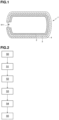
- FIG 1 shows a fibre composite tank 1 according to an embodiment of the invention.
- the tank 1 is cylindrical.
- the tank 1 has an internal volume in the range of 60 liters to 2000 liters, or even more.
- the fibre composite tank 1 comprises an inner barrier layer 2 and a first shell layer 3.
- An optional second shell layer 4 can be observed on Figure 1 .
- the presence of the second shell layer 4 depends on the value of the pressure that the fibre composite tank 1 has to withstand. Typically, the second shell layer 4 is needed when the fibre composite tank 1 has to withstand a pressure of the order of 50 bar or higher.
- the tank 1 comprises one or two openings.
- the tank comprises only one opening 911.
- the openings are placed at two opposite ends of the tank 1, preferably facing each other.
- the fibre composite tank 1 can contain diverse types of fluids. By “fluids”, it is meant gases or liquids. Examples of gases that can be contained in the fibre composite tank 1 are hydrogen, oxygen, or nitrogen.
- a reusable and removable tool kit is assembled.
- the elongated segments 6 of the tool kit 5 are made of metal, for instance of aluminium, aluminium alloy, steel or stainless steel.
- a step S1 two end fittings are applied to the assembled tool kit 5.
- the end fittings 91, 92 are shifted over the first and the second spindle parts 81 and 82.
- Figure 5 shows the assembled tool kit with two end fittings 91 and 92 applied on it.
- only one end fitting 91 may be applied on the assembled removable tool kit.
- Each of the two end fittings 91 and 92 comprises an opening 911, 921 large enough to enable the disassembly and removal of the removable tool kit 5 through the opening 911, 921.
- the opening 911, 912 is dimensioned to enable the parts of the removable tool kit 5, once disassembled, to pass through the opening 911, 921.
- the end fittings 91 and 92 are made of plastic. In this case, they are well suited to produce a small, lightweight tank able to withstand moderate overpressure, for instance lower than 50 bar
- the end fittings 91 and 92 are in a polymer compatible with the material of the inner layer 2 and of the first shell layer 3... In this case, they are well suited to produce tanks able to withstand high pressure, for instance higher than 50 bar.
- the breather piece 11 has dimensions suitable for covering the whole surface of the assembled tool kit 5. Typically, the breather piece 11 is cut to the dimensions of the assembled tool kit 5 and laid on the assembled tool kit 5.
- the breather comprises a mass per area unit comprised between 110 g/m 2 and 600 g/m 2 .
- the mass per surface of the breather is chosen so as to adapt the tightness of the tank.
- the breather piece 11 comprises a thickness of 2 or 3 mm. Once swaddled, the breather piece 11 forms the inner barrier layer 2.
- the breather comprises a glass transition temperature higher than the working temperature of subsequent steps of the method for producing the fibre composite tank 1, that will be further described.
- the breather comprises a glass transition temperature higher than 60 ° C.
- the glass transition temperature of the breather is notably suitable for heating per infrared radiation.
- the breather piece 11 covers the end fitting 91, 92 outside the opening 911, 921 up to the outer peripheral portion 10.
- the inner barrier layer 2 is not formed by winding a film, but by simply swaddling the assembled tool kit 5 with the breather piece 11. There is thus no need for a whole equipment suitable for film winding and no winding step.
- a diverse choice for the breather material is thus possible, facilitating the production of the fibre composite tank.
- the breather material can be polyester or polyamide.
- the breather can be made out of polymers identical to the polymers the first shell layer 3 is made of. It is notably easier to find a breather material that is chemically compatible with resins of shell layers that will be described further than to find a film compatible with those resins.
- a step S3 is carried out where a first composite tape 12 is wound around the breather piece 11 under heat and pressure with a film winding machine
- the pressure conditions come from the tension applied on the first composite tape 12 during winding.
- the heat conditions are realized for instance by infrared radiation, or by any other heating means. In the case of heating by infrared radiation, the radiation wavelength is chosen according to the nature of the material of the first composite tape 12.
- the first composite tape 12 is made of a first composite material mixing fibre and resin.
- the first composite material can be high-strength fibre, such as glass fibre or carbon fibre, impregnated by a thermoplastic resin.
- the fibre of the first composite material may be metal fibre, mineral fibre, or a combination of those fibres.
- resin for the first composite material are polyamide 11 (PA11), polyamide 12 (PA12), polyamide 66 (PA66), polyphthalamide (PPA).
- Figure 7 shows the assembled tool kit 5 swaddled with the breather piece 11 at an early stage of the winding step.
- the spindle parts 81, 82 are not represented on Figure 7 .
- the assembled tool kit 5 has a monotonically decreasing diameter, ranging from Dmax at its equatorial down to Dmin at its opposite ends.
- the first composite tape 12 is applied as a single continuous strip.
- the first composite tape 12 is applied as a succession of several fragments.
- Figure 9 shows the assembled tool kit 5 swaddled with the breather piece 11 after the first composite tape 12 is completely wound. Again, for clarity, the spindle parts 81, 82 are not represented on Figure 9 .
- the opening 911, 921 is left uncovered by the first composite tape 12 for removal of the tool kit 5.
- the area covered by the first composite tape 12 can be larger or smaller than the area covered by the breather piece 11, but is preferably the same.
- the end fitting 91, 92 comprises an outer peripheral portion 10 around the opening 911, 921 as illustrated on Figure 6
- the first composite tape 12 covers the end fitting outside the opening 911, 921 up to the outer peripheral portion 10.
- the wound first composite tape 12 forms the first shell layer 3 of the fibre composite tank 1.
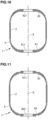
- Figure 10 shows an embodiment of the fibre composite tank 1, where the end fittings 91, 92 are located inside the inner barrier layer 2 formed by the breather piece 11. It can be observed that both openings 911, 921 are left uncovered.
- the openings 911 and 921 are closed with end caps.
- the end caps are overmoulded bosses that are welded on the openings 911, 921.
- the end caps are overmoulded metallic parts, but for working pressures less than 50 bar, they can be made of polymer or reinforced polymer only.
- the resin of the second composite material is preferably chemically compatible with the material of the component it is wound on, that is, the first composite material.
- the second composite tape 13 is applied as a single continuous strip. Alternately, the second composite tape 13 is applied as a succession of several fragments. At the end of the additional step S5, the wound second composite tape 13 forms the second shell layer 4.
Landscapes
- Engineering & Computer Science (AREA)
- Mechanical Engineering (AREA)
- Chemical & Material Sciences (AREA)
- Composite Materials (AREA)
- General Engineering & Computer Science (AREA)
- Manufacturing & Machinery (AREA)
- Filling Or Discharging Of Gas Storage Vessels (AREA)
- Moulding By Coating Moulds (AREA)
- Pressure Vessels And Lids Thereof (AREA)
Abstract
- a step (S0) of assembling a reusable and removable tool kit (5);
- a step (S1) of applying an end fitting (91,92) to the tool kit (5), said end fitting (91,92) having an opening (911,921) large enough for removing the tool kit (5) there through after being disassembled;
- a step (S2) of forming a barrier layer (2) by swaddling the assembled tool kit (5) with a breather piece (11);
- a step (S3) of forming a first shell layer (3) by winding a first composite tape (12), made of a first composite material mixing fibre and resin, over the barrier layer (2);
- a step (S4) of disassembling and removing the tool kit (5) through the opening (911,921).
Description
- The invention relates to pressurized fluid storage tanks.
- More specifically, the invention relates to a method for producing a fibre composite cylindrical tank for containing a pressurised fluid and a fibre composite cylindrical tank obtained by this method.
- The use of high-pressure fibre composite tanks is increasing notably for hydrogen transportation. A thermoplastic type V tank constitutes an interesting composite tank design to comply with hydrogen usage.
- Usually, so-called thermoplastic type V tanks present a homogeneous liner made from the same resin as the tank. The term "liner" is used here to describe the part on the inner surface of the tank that guarantees the tightness of the tank. Alternatively, type V tanks may have no liner.
- Linerless type V tanks can be produced by winding, around a removable tool kit, a fibre composite film playing the role of a barrier layer and with the same resin used for the tank, making the tank more homogeneous, as described in the international patent application
WO2011/143723 by one of the co-applicants of this application. - Winding a film around the whole surface of the removable tool kit, which matches the tank surface, might be time consuming and requires the use of a winding machine. Besides, while winding, the film might tear, which increases the need to reiterate the winding process. Also, it is often difficult to find a film made of a material that is chemically compatible with the resin used for the tank.
- The present application presents an improvement of the method described in the international patent application
WO2011/143723 in order to produce a linerless type V composite tank. - There is a need for a storage tank for pressurized fluids with homogeneous walls guaranteeing the tank tightness, as well as a need for convenient method for producing such storage tank.
- To this end, the invention relates to a method for producing a fibre composite cylindrical tank for containing a fluid, comprising the following steps:
- a step of assembling a reusable and removable tool kit;
- a step of applying an end fitting to the tool kit, said end fitting having an opening large enough for removing the tool kit there through after being disassembled;
- a step of forming a barrier layer by swaddling the assembled tool kit with a breather piece;
- a step of forming a first shell layer by winding a first composite tape, made of a first composite material mixing fibre and resin, over the barrier layer;
- a step of disassembling and removing the tool kit through the opening.
- The invention removes a film winding step in a method of producing a fibre composite tank, thereby shortening the producing time. Also, the use of a breather material widens the choice of materials chemically compatible with the first composite tape and thus facilitates the production method.
- In an embodiment, the method further comprises a step of forming a second shell layer by winding a second composite tape made of a second composite material mixing fibre and resin over the first shell layer and over an outer peripheral portion of the end fitting, said outer peripheral portion surrounding the opening. The second shell layer allows for the fibre composite tank to withstand higher pressure values, typically working pressures of 700 bar.
- Advantageously, the breather piece is made of polyester or polyamide or any other polymer chemically compatible with the resins of the first composite material and of the second composite material. The breather can also be a combination of different polymers such as polyester and polyamide for instance.
- Advantageously, the breather piece comprises a mass per area unit comprised between 110 g/m2 and 600 g/m2. The choice of the mass per area unit of the breather piece allows adjusting the desired tightness of the fibre composite tank.
- Advantageously, the breather piece comprises a thickness comprised between 2 and 3 mm.
- Advantageously, the breather comprises a glass transition temperature higher than 50 °C. The choice of the glass transition temperature of the breather allows implementing the invention under the conditions of existing production methods.
- Advantageously, the breather piece and the first composite material are chemically compatible. The breather piece and the first composite material form together a monolithic structure. This allows improving the homogeneity of the walls of the fibre composite tank, and thus of the tightness of the latter.
- Advantageously, the first composite material is a thermoplastic material.
- Advantageously, the first composite material comprises carbon fibres, glass fibres or Basalt fibres.
- Another aspect of the invention relates to a fibre composite cylindrical tank for containing a fluid produced by a method according to the invention, comprising a shell layer composed of a mix of a breather, a resin and fibre, and comprising an end fitting, the shell layer and the end fitting forming a unitary rigid structure able to withstand an overpressure of at least 2 bar. The fibre composite cylindrical tank obtained by this method can thus be produced more rapidly than fibre composite tanks from the prior art, while being able to withstand overpressures.
- The invention is further elucidated in the appending figures and figure description explaining preferred embodiments of the invention. Note that the figures are not drawn to scale. The figures are intended to describe the principles of the invention.
-
Figure 1 represents a schematic cross-sectional view of a fibre composite tank according to the invention. -
Figure 2 illustrates the main steps of a method for producing a fibre composite tank according to the invention. -
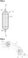
Figure 3 represents schematically an assembled tool kit suitable for implementing a method of producing a fibre composite tank according to the invention. -
Figure 4 represents schematically a subset of parts of the tool kit ofFigure 2 . -
Figure 5 represents schematically the assemble tool kit ofFigure 2 with two end fittings. -
Figure 6 represents schematically an embodiment an end fitting with an opening. -
Figure 7 represents schematically a fibre composite tank according to the invention at an early stage of a first winding step of the method according to the invention. -
Figure 8 represents schematically a fibre composite tank according to the invention at a later stage of the first winding step of the method according to the invention -
Figure 9 represents schematically a fibre composite tank according to the invention after the first winding step of the method according to the invention has been completed. -
Figure 10 represents a schematic cross-sectional view of a fibre composite tank according to one embodiment of the invention. -
Figure 11 represents a schematic cross-sectional view of fibre composite tank according to a second embodiment of the invention. - Unless stated otherwise, a same element appearing on different figures presents a single reference.
- Furthermore, the terms "first", "second", and the like in the description and in the claims, are used for distinguishing between similar elements and not necessarily for describing a sequential or chronological order.
-
Figure 1 shows afibre composite tank 1 according to an embodiment of the invention. OnFigure 1 , thetank 1 is cylindrical. Thetank 1 has an internal volume in the range of 60 liters to 2000 liters, or even more. Thefibre composite tank 1 comprises aninner barrier layer 2 and afirst shell layer 3. An optionalsecond shell layer 4 can be observed onFigure 1 . The presence of thesecond shell layer 4 depends on the value of the pressure that thefibre composite tank 1 has to withstand. Typically, thesecond shell layer 4 is needed when thefibre composite tank 1 has to withstand a pressure of the order of 50 bar or higher. - According to the embodiments, the
tank 1 comprises one or two openings. In the embodiment ofFigure 1 , the tank comprises only oneopening 911. In the embodiments wherein thetank 1 comprises two openings (embodiments ofFigures 10 and 11 , for example), the openings are placed at two opposite ends of thetank 1, preferably facing each other. - The
fibre composite tank 1 can contain diverse types of fluids. By "fluids", it is meant gases or liquids. Examples of gases that can be contained in thefibre composite tank 1 are hydrogen, oxygen, or nitrogen. - In what follows, a method for producing the
fibre composite tank 1 illustrated onFigure 1 will be described. This method is an improvement of the method described in the international patent applicationWO2011/143723 and contains common steps that will be described below. A more detailed description of those common steps may be found in the above-mentioned international patent application. -
Figure 2 schematically illustrates the main steps of the method for producing thefibre composite tank 1 according to the invention. - In a step S0, a reusable and removable tool kit is assembled.
-
Figure 3 shows an example of aremovable tool kit 5 that can be used in the method of the present description. Theremovable tool kit 5 comprises a plurality ofelongated segments 6 that are placed side by side to form a rounded outer surface. Thetool kit 5 has a rotationally symmetric shape with a varying outer diameter around a symmetry axis XX and is suitable for film winding. This geometry provides flexibility in the choice of shapes of thefibre composite tank 1 to produce. Thefibre composite tank 1 may be cylindrical, spherical, ellipsoidal, or of any other shape. - The
elongated segments 6 of thetool kit 5 are made of metal, for instance of aluminium, aluminium alloy, steel or stainless steel. - While assembling the
tool kit 5, theelongated segments 6 are hold together using segment holders 7 and twospindle parts elongated segments 6 are held in position by pulling thespindle parts spindle parts elongated segments 6.Figure 4 shows a subset of theelongated segments 6 hold by two segment holders 7 arranged on the twospindle parts - In a step S1, two end fittings are applied to the assembled
tool kit 5. To apply theend fittings tool kit 5, theend fittings second spindle parts Figure 5 shows the assembled tool kit with twoend fittings end fittings opening removable tool kit 5 through theopening opening 911, 912 is dimensioned to enable the parts of theremovable tool kit 5, once disassembled, to pass through theopening - The
end fittings fibre composite tank 1. - In some embodiments, the
end fittings - In some embodiments, the
end fittings inner layer 2 and of thefirst shell layer 3... In this case, they are well suited to produce tanks able to withstand high pressure, for instance higher than 50 bar. - The material of the
end fittings fibre composite tank 1 -
Figure 6 shows an embodiment of the end fitting 91, 92. OnFigure 6 , an outerperipheral portion 10 surrounding theopening openings tool kit 5 so as to allow their removal. In the example ofFigure 6 , theopenings - After steps S0 and S1, in a step S2, the assembled
tool kit 5 together with theend fittings breather piece 11. By "breather", it is meant a non-woven material made of fibres. For instance, the breather can be polyester or polyamide. The breather can be made out of polymers identical to the polymers thefirst shell layer 3 is made of. Typically, the breather is felt. Felt is a non-woven textile material that is produced by matting, condensing and pressing fibers together. - The
breather piece 11 has dimensions suitable for covering the whole surface of the assembledtool kit 5. Typically, thebreather piece 11 is cut to the dimensions of the assembledtool kit 5 and laid on the assembledtool kit 5. The breather comprises a mass per area unit comprised between 110 g/m2 and 600 g/m2. The mass per surface of the breather is chosen so as to adapt the tightness of the tank. Typically, thebreather piece 11 comprises a thickness of 2 or 3 mm. Once swaddled, thebreather piece 11 forms theinner barrier layer 2. - In some embodiments, the breather comprises a glass transition temperature higher than the working temperature of subsequent steps of the method for producing the
fibre composite tank 1, that will be further described. For instance, the breather comprises a glass transition temperature higher than 60 ° C. The glass transition temperature of the breather is notably suitable for heating per infrared radiation. - For instance, when the end fitting 91, 92 comprises an outer
peripheral portion 10 around theopening Figure 6 , thebreather piece 11 covers the end fitting 91, 92 outside theopening peripheral portion 10. - Thus, differently from the method disclosed in in the international patent application
WO2011/143723 , theinner barrier layer 2 is not formed by winding a film, but by simply swaddling the assembledtool kit 5 with thebreather piece 11. There is thus no need for a whole equipment suitable for film winding and no winding step. A diverse choice for the breather material is thus possible, facilitating the production of the fibre composite tank. For example, the breather material can be polyester or polyamide. The breather can be made out of polymers identical to the polymers thefirst shell layer 3 is made of. It is notably easier to find a breather material that is chemically compatible with resins of shell layers that will be described further than to find a film compatible with those resins. - After step S2, a step S3 is carried out where a first
composite tape 12 is wound around thebreather piece 11 under heat and pressure with a film winding machine The pressure conditions come from the tension applied on the firstcomposite tape 12 during winding. The heat conditions are realized for instance by infrared radiation, or by any other heating means. In the case of heating by infrared radiation, the radiation wavelength is chosen according to the nature of the material of the firstcomposite tape 12. The firstcomposite tape 12 is made of a first composite material mixing fibre and resin. For instance, the first composite material can be high-strength fibre, such as glass fibre or carbon fibre, impregnated by a thermoplastic resin. In another example, the fibre of the first composite material may be metal fibre, mineral fibre, or a combination of those fibres. Examples of resin for the first composite material are polyamide 11 (PA11), polyamide 12 (PA12), polyamide 66 (PA66), polyphthalamide (PPA). -
Figure 7 shows the assembledtool kit 5 swaddled with thebreather piece 11 at an early stage of the winding step. For clarity, thespindle parts Figure 7 . OnFigure 7 , the assembledtool kit 5 has a monotonically decreasing diameter, ranging from Dmax at its equatorial down to Dmin at its opposite ends. Preferably, the firstcomposite tape 12 is applied as a single continuous strip. Alternatively, the firstcomposite tape 12 is applied as a succession of several fragments. A detailed description of the winding process and parameters can be found in the international patent applicationWO2011/143723 . - The breather material is chosen so as to be chemically compatible with the resin of the first composite material. By "chemically compatible", it is meant that during step S6, chemical bonds are created between the breather material and the resin of the first composite material. For instance, while winding the first
composite tape 12, thebreather piece 11 is filled with particles from the resin of the first composite material. The first composite material builds the tightness of thetank 1. -
Figure 8 shows the assembledtool kit 5 swaddled with thebreather piece 11 at a later stage of the winding step. Only the firstcomposite tape 12 is visible, the swaddledtool kit 5 and theend fittings spindle parts Figure 8 . -
Figure 9 shows the assembledtool kit 5 swaddled with thebreather piece 11 after the firstcomposite tape 12 is completely wound. Again, for clarity, thespindle parts Figure 9 . Theopening composite tape 12 for removal of thetool kit 5. The area covered by the firstcomposite tape 12 can be larger or smaller than the area covered by thebreather piece 11, but is preferably the same. For instance, when the end fitting 91, 92 comprises an outerperipheral portion 10 around theopening Figure 6 , the firstcomposite tape 12 covers the end fitting outside theopening peripheral portion 10. The wound firstcomposite tape 12 forms thefirst shell layer 3 of thefibre composite tank 1. -
Figure 10 shows an embodiment of thefibre composite tank 1, where theend fittings inner barrier layer 2 formed by thebreather piece 11. It can be observed that bothopenings - In another embodiment, step S2 occurs before step S1. In other words, the assembled
tool kit 5 is swaddled with thebreather piece 11 before bothend fittings tool kit 5. The firstcomposite tape 12 is wound after bothend fittings Figure 11 shows a correspondingfibre composite tank 1, where theend fittings inner barrier layer 2 formed by thebreather piece 11 and thefirst shell layer 3 formed by the wound firstcomposite tape 12. - Once the first
composite tape 12 has been wound, in a following step S4, the tool kit is disassembled and its different parts are removed from thefibre composite tank 1 through at least one of theopenings spindle parts tank 1, removing the segment holders 7 from thespindle parts 81,82 (e.g. by inserting a hand inside thehollow spindle parts 81, 82), extracting thespindle parts tank 1, removing the segment holders 7 and theelongated segments 6 out of thetank 1 through theopening end fittings - After the
removable tool kit 5 has been completely disassembled and removed from thetank 1, theopenings openings - The
inner barrier layer 2, thefirst shell layer 3 and theend fittings - In some embodiments, an additional step S5 following the disassembling and removal of the
tool kit 5 is carried out. After the removal of thetool kit 5, the openings are closed by welding overmoulded metal bosses on theend fittings composite tape 12. The second composite tape 13 is made of a second composite material mixing fibre and resin. For instance, the second composite material can be high-strength fibre such as glass fibre, basalt fibre, carbon fibre, or any other fibre impregnated by a thermoplastic resin. In another example, the fibre of the second composite material may be metal fibre, mineral fibre, or a combination of those fibres. The resin of the second composite material is preferably chemically compatible with the material of the component it is wound on, that is, the first composite material. Preferably, the second composite tape 13 is applied as a single continuous strip. Alternately, the second composite tape 13 is applied as a succession of several fragments. At the end of the additional step S5, the wound second composite tape 13 forms thesecond shell layer 4. - The
inner barrier layer 2, thefirst shell layer 3, theend fittings second shell layer 4 form a unitary rigid structure able to withstand an overpressure of at least 50 bar, or even more. The overpressure limit value depends on the composition, that is the assembly of materials, formed by theinner barrier layer 2, thefirst shell layer 3, theend fittings second shell layer 4. - The invention can be used to produce a wide variety of fibre composite tanks for different applications, such as containers for storage for instance of hydrogen, helium, nitrogen, water, alkali, liquid acid, etc. The dimensions of the
fibre composite tank 1 can range from 60 L to 2 000 L or even more.
Claims (10)
- Method for producing a fibre composite cylindrical tank (1) for containing a fluid, comprising the following steps:- a step (S0) of assembling a reusable and removable tool kit (5);- a step (S1) of applying an end fitting (91,92) to the tool kit (5), said end fitting (91,92) having an opening (911, 921) large enough for removing the tool kit (5) there through after being disassembled;- a step (S2) of forming a barrier layer (2) by swaddling the assembled tool kit (5) with a breather piece (11);- a step (S3) of forming a first shell layer (3) by winding a first composite tape (12), made of a first composite material mixing fibre and resin, over the barrier layer (2);- a step (S4) of disassembling and removing the tool kit (5) through the opening (911, 921).
- Method according to claim 1, further comprising a step (S10) of forming a second shell layer (4) by winding a second composite tape (13) made of a second composite material mixing fibre and resin over the first shell layer (3) and over an outer peripheral portion (10) of the end fitting (91,92), said outer peripheral portion (10) surrounding the opening (91,92).
- Method according to claim 2, characterized in that the breather piece (11) is made of polyester and/or polyamide compatible with resins of the first composite material and of the second composite material.
- Method according to one of the preceding claims, characterized in that the breather piece (11) comprises a mass per area unit comprised between 110 g/m2 and 600 g/m2.
- Method according to one of the preceding claims, characterized in that the breather piece (11) comprises a thickness comprised between 2 and 3 mm.
- Method according to one of the preceding claims, wherein the breather comprises a glass transition temperature higher than 50 °C.
- Method according to one of the preceding claims, wherein the breather piece (11) and the first composite material are chemically compatible.
- Method according to one of the preceding claims, wherein the first composite material comprises a thermoplastic material.
- Method according to one of the preceding claims, wherein the first composite material comprises carbon fibres, glass fibres, or Basalt fibres.
- A fibre composite cylindrical tank (1) for containing a fluid, produced by a method according to any of claims 1 to 9, comprising a shell layer comprising a mix of a breather, a resin and fibre, and comprising an end fitting, characterized in that the shell layer and the end fitting form a unitary rigid structure able to withstand an overpressure of at least 2 bar.
Priority Applications (5)
| Application Number | Priority Date | Filing Date | Title |
|---|---|---|---|
| EP22305909.8A EP4296558B1 (en) | 2022-06-23 | 2022-06-23 | Method for producing a composite cylindrical tank and composite tank produced by this method |
| US18/334,032 US12377620B2 (en) | 2022-06-23 | 2023-06-13 | Method for producing a composite cylindrical tank and composite tank produced by this method |
| JP2023098955A JP2024002944A (en) | 2022-06-23 | 2023-06-16 | Method for manufacturing a composite cylindrical tank and a composite tank manufactured by this method |
| CN202310737949.9A CN117329433A (en) | 2022-06-23 | 2023-06-21 | Method for manufacturing composite cylindrical can and composite can manufactured by the method |
| KR1020230081294A KR20240001070A (en) | 2022-06-23 | 2023-06-23 | Method for producing a composite cylindrical tank and composite tank produced by this method |
Applications Claiming Priority (1)
| Application Number | Priority Date | Filing Date | Title |
|---|---|---|---|
| EP22305909.8A EP4296558B1 (en) | 2022-06-23 | 2022-06-23 | Method for producing a composite cylindrical tank and composite tank produced by this method |
Publications (2)
| Publication Number | Publication Date |
|---|---|
| EP4296558A1 true EP4296558A1 (en) | 2023-12-27 |
| EP4296558B1 EP4296558B1 (en) | 2026-08-05 |
Family
ID=82748389
Family Applications (1)
| Application Number | Title | Priority Date | Filing Date |
|---|---|---|---|
| EP22305909.8A Active EP4296558B1 (en) | 2022-06-23 | 2022-06-23 | Method for producing a composite cylindrical tank and composite tank produced by this method |
Country Status (5)
| Country | Link |
|---|---|
| US (1) | US12377620B2 (en) |
| EP (1) | EP4296558B1 (en) |
| JP (1) | JP2024002944A (en) |
| KR (1) | KR20240001070A (en) |
| CN (1) | CN117329433A (en) |
Families Citing this family (2)
| Publication number | Priority date | Publication date | Assignee | Title |
|---|---|---|---|---|
| TW202413787A (en) * | 2022-08-01 | 2024-04-01 | 日商東洋工程股份有限公司 | Compressed air storage container, compressed air storage device, usage method of compressed air storage device, power generation device, power generation method |
| BE1033010B1 (en) * | 2024-10-22 | 2026-05-26 | Covess N V | PRESSURE VESSEL AND METHOD FOR ITS MANUFACTURE |
Citations (4)
| Publication number | Priority date | Publication date | Assignee | Title |
|---|---|---|---|---|
| US2744043A (en) * | 1950-01-23 | 1956-05-01 | Fels & Company | Method of producing pressure containers for fluids |
| WO2011143723A2 (en) | 2010-05-17 | 2011-11-24 | Covess N.V. | Method for producing a leak-tight vessel, and a leak-tight vessel |
| US8932695B1 (en) * | 2012-01-04 | 2015-01-13 | CleanNG, LLC | Basalt-based pressure vessel for gas storage and method for its production |
| US20210129662A1 (en) * | 2019-11-06 | 2021-05-06 | GM Global Technology Operations LLC | Hydrogen storage tank having a nanoporous breather layer |
Family Cites Families (5)
| Publication number | Priority date | Publication date | Assignee | Title |
|---|---|---|---|---|
| US3047191A (en) * | 1957-11-26 | 1962-07-31 | Hercules Powder Co Ltd | Filament wound vessels and methods for forming same |
| US3260398A (en) * | 1962-01-29 | 1966-07-12 | Whittaker Corp | Woven reinforcement for composite structure |
| US3367815A (en) * | 1964-12-14 | 1968-02-06 | Metal Containers Ltd | Method and apparatus for forming filament wound vessels |
| WO2011144234A1 (en) * | 2010-05-17 | 2011-11-24 | Covess | Method for producing a leak-tight vessel, and a leak tight vessel |
| EP2571671B1 (en) * | 2010-05-17 | 2015-07-29 | Covess N.V. | Method for producing a leak-tight vessel, and leak-tight vessel produced by said method |
-
2022
- 2022-06-23 EP EP22305909.8A patent/EP4296558B1/en active Active
-
2023
- 2023-06-13 US US18/334,032 patent/US12377620B2/en active Active
- 2023-06-16 JP JP2023098955A patent/JP2024002944A/en active Pending
- 2023-06-21 CN CN202310737949.9A patent/CN117329433A/en active Pending
- 2023-06-23 KR KR1020230081294A patent/KR20240001070A/en active Pending
Patent Citations (4)
| Publication number | Priority date | Publication date | Assignee | Title |
|---|---|---|---|---|
| US2744043A (en) * | 1950-01-23 | 1956-05-01 | Fels & Company | Method of producing pressure containers for fluids |
| WO2011143723A2 (en) | 2010-05-17 | 2011-11-24 | Covess N.V. | Method for producing a leak-tight vessel, and a leak-tight vessel |
| US8932695B1 (en) * | 2012-01-04 | 2015-01-13 | CleanNG, LLC | Basalt-based pressure vessel for gas storage and method for its production |
| US20210129662A1 (en) * | 2019-11-06 | 2021-05-06 | GM Global Technology Operations LLC | Hydrogen storage tank having a nanoporous breather layer |
Also Published As
| Publication number | Publication date |
|---|---|
| JP2024002944A (en) | 2024-01-11 |
| KR20240001070A (en) | 2024-01-03 |
| US20230415435A1 (en) | 2023-12-28 |
| US12377620B2 (en) | 2025-08-05 |
| EP4296558B1 (en) | 2026-08-05 |
| CN117329433A (en) | 2024-01-02 |
Similar Documents
| Publication | Publication Date | Title |
|---|---|---|
| US12377620B2 (en) | Method for producing a composite cylindrical tank and composite tank produced by this method | |
| US11299312B2 (en) | Method for producing a leak-tight vessel, and a leak-tight vessel | |
| JP4588307B2 (en) | Pressure vessel manufacturing method | |
| AU2020260452B2 (en) | High-pressure tank and method for manufacturing high-pressure tank | |
| JP6928010B2 (en) | Pressure vessel with tape-based reinforcement structure | |
| US10487981B2 (en) | High-pressure composite vessel and the method of manufacturing high-pressure composite vessel | |
| US11073240B2 (en) | Pressure vessel dome vents | |
| EP2571671B1 (en) | Method for producing a leak-tight vessel, and leak-tight vessel produced by said method | |
| US20210404603A1 (en) | Compressed gas storage unit with preformed endcaps | |
| US20210221081A1 (en) | Manufacturing method for high-pressure tank | |
| JP2005113971A (en) | Liner for pressure vessel | |
| US4671831A (en) | Method of manufacture of large high pressure composite bottles | |
| WO2011144234A1 (en) | Method for producing a leak-tight vessel, and a leak tight vessel | |
| JP4431351B2 (en) | Pressure vessel manufacturing method | |
| JP2024525825A (en) | Boss Assembly for Pressure Vessel | |
| EP4607081A1 (en) | New method for producing a composite tank and new composite tank produced by this method | |
| US20250146621A1 (en) | Process for production of a sealed tank to contain a gas and/or a fluid | |
| EP2788664A1 (en) | Composite pressure vessel and method for manufacturing the same | |
| CA3149338A1 (en) | Method of manufacturing a pressure vessel and pressure vessel | |
| US20250074008A1 (en) | Linerless filament wound composite tanks and modular manufacturing methods | |
| EP4711120A1 (en) | Method for producing cryogenic tank | |
| CN116901478B (en) | Cans and methods for manufacturing cans | |
| WO2026087462A1 (en) | Leak-tight vessel and method for its manufacturing |
Legal Events
| Date | Code | Title | Description |
|---|---|---|---|
| PUAI | Public reference made under article 153(3) epc to a published international application that has entered the european phase |
Free format text: ORIGINAL CODE: 0009012 |
|
| STAA | Information on the status of an ep patent application or granted ep patent |
Free format text: STATUS: THE APPLICATION HAS BEEN PUBLISHED |
|
| AK | Designated contracting states |
Kind code of ref document: A1 Designated state(s): AL AT BE BG CH CY CZ DE DK EE ES FI FR GB GR HR HU IE IS IT LI LT LU LV MC MK MT NL NO PL PT RO RS SE SI SK SM TR |
|
| STAA | Information on the status of an ep patent application or granted ep patent |
Free format text: STATUS: REQUEST FOR EXAMINATION WAS MADE |
|
| 17P | Request for examination filed |
Effective date: 20240517 |
|
| RBV | Designated contracting states (corrected) |
Designated state(s): AL AT BE BG CH CY CZ DE DK EE ES FI FR GB GR HR HU IE IS IT LI LT LU LV MC MK MT NL NO PL PT RO RS SE SI SK SM TR |
|
| GRAP | Despatch of communication of intention to grant a patent |
Free format text: ORIGINAL CODE: EPIDOSNIGR1 |
|
| STAA | Information on the status of an ep patent application or granted ep patent |
Free format text: STATUS: GRANT OF PATENT IS INTENDED |
|
| RIC1 | Information provided on ipc code assigned before grant |
Ipc: F17C 1/06 20060101AFI20250930BHEP Ipc: B29C 70/08 20060101ALI20250930BHEP Ipc: B29C 53/60 20060101ALI20250930BHEP Ipc: B29C 53/82 20060101ALI20250930BHEP Ipc: B29C 70/86 20060101ALI20250930BHEP Ipc: F17C 1/02 20060101ALI20250930BHEP Ipc: B29C 63/24 20060101ALI20250930BHEP Ipc: B29C 63/26 20060101ALI20250930BHEP Ipc: B29C 53/58 20060101ALN20250930BHEP Ipc: B29K 101/12 20060101ALN20250930BHEP Ipc: B29K 105/24 20060101ALN20250930BHEP Ipc: B29L 31/00 20060101ALN20250930BHEP |
|
| INTG | Intention to grant announced |
Effective date: 20251016 |
|
| GRAJ | Information related to disapproval of communication of intention to grant by the applicant or resumption of examination proceedings by the epo deleted |
Free format text: ORIGINAL CODE: EPIDOSDIGR1 |
|
| STAA | Information on the status of an ep patent application or granted ep patent |
Free format text: STATUS: REQUEST FOR EXAMINATION WAS MADE |
|
| GRAP | Despatch of communication of intention to grant a patent |
Free format text: ORIGINAL CODE: EPIDOSNIGR1 |
|
| STAA | Information on the status of an ep patent application or granted ep patent |
Free format text: STATUS: GRANT OF PATENT IS INTENDED |
|
| INTC | Intention to grant announced (deleted) | ||
| INTG | Intention to grant announced |
Effective date: 20260120 |
|
| RIC1 | Information provided on ipc code assigned before grant |
Ipc: F17C 1/06 20060101AFI20260109BHEP Ipc: B29C 70/08 20060101ALI20260109BHEP Ipc: B29C 53/60 20060101ALI20260109BHEP Ipc: B29C 53/82 20060101ALI20260109BHEP Ipc: B29C 70/86 20060101ALI20260109BHEP Ipc: F17C 1/02 20060101ALI20260109BHEP Ipc: B29C 63/24 20060101ALI20260109BHEP Ipc: B29C 63/26 20060101ALI20260109BHEP Ipc: B29C 53/58 20060101ALN20260109BHEP Ipc: B29K 101/12 20060101ALN20260109BHEP Ipc: B29K 105/24 20060101ALN20260109BHEP Ipc: B29L 31/00 20060101ALN20260109BHEP |
|
| GRAS | Grant fee paid |
Free format text: ORIGINAL CODE: EPIDOSNIGR3 |
|
| GRAA | (expected) grant |
Free format text: ORIGINAL CODE: 0009210 |
|
| STAA | Information on the status of an ep patent application or granted ep patent |
Free format text: STATUS: THE PATENT HAS BEEN GRANTED |
|
| AK | Designated contracting states |
Kind code of ref document: B1 Designated state(s): AL AT BE BG CH CY CZ DE DK EE ES FI FR GB GR HR HU IE IS IT LI LT LU LV MC MK MT NL NO PL PT RO RS SE SI SK SM TR |
|
| REG | Reference to a national code |
Ref country code: CH Ref legal event code: F10 Free format text: ST27 STATUS EVENT CODE: U-0-0-F10-F00 (AS PROVIDED BY THE NATIONAL OFFICE) Effective date: 20260805 |