EP4296528A1 - Thrust needle roller bearing - Google Patents
Thrust needle roller bearing Download PDFInfo
- Publication number
- EP4296528A1 EP4296528A1 EP22756310.3A EP22756310A EP4296528A1 EP 4296528 A1 EP4296528 A1 EP 4296528A1 EP 22756310 A EP22756310 A EP 22756310A EP 4296528 A1 EP4296528 A1 EP 4296528A1
- Authority
- EP
- European Patent Office
- Prior art keywords
- oil repellent
- oil
- bearing
- needle roller
- test
- Prior art date
- Legal status (The legal status is an assumption and is not a legal conclusion. Google has not performed a legal analysis and makes no representation as to the accuracy of the status listed.)
- Pending
Links
Images



Classifications
-
- F—MECHANICAL ENGINEERING; LIGHTING; HEATING; WEAPONS; BLASTING
- F16—ENGINEERING ELEMENTS AND UNITS; GENERAL MEASURES FOR PRODUCING AND MAINTAINING EFFECTIVE FUNCTIONING OF MACHINES OR INSTALLATIONS; THERMAL INSULATION IN GENERAL
- F16C—SHAFTS; FLEXIBLE SHAFTS; ELEMENTS OR CRANKSHAFT MECHANISMS; ROTARY BODIES OTHER THAN GEARING ELEMENTS; BEARINGS
- F16C19/00—Bearings with rolling contact, for exclusively rotary movement
- F16C19/22—Bearings with rolling contact, for exclusively rotary movement with bearing rollers essentially of the same size in one or more circular rows, e.g. needle bearings
- F16C19/30—Bearings with rolling contact, for exclusively rotary movement with bearing rollers essentially of the same size in one or more circular rows, e.g. needle bearings for axial load mainly
- F16C19/305—Bearings with rolling contact, for exclusively rotary movement with bearing rollers essentially of the same size in one or more circular rows, e.g. needle bearings for axial load mainly consisting of rollers held in a cage
-
- F—MECHANICAL ENGINEERING; LIGHTING; HEATING; WEAPONS; BLASTING
- F16—ENGINEERING ELEMENTS AND UNITS; GENERAL MEASURES FOR PRODUCING AND MAINTAINING EFFECTIVE FUNCTIONING OF MACHINES OR INSTALLATIONS; THERMAL INSULATION IN GENERAL
- F16C—SHAFTS; FLEXIBLE SHAFTS; ELEMENTS OR CRANKSHAFT MECHANISMS; ROTARY BODIES OTHER THAN GEARING ELEMENTS; BEARINGS
- F16C19/00—Bearings with rolling contact, for exclusively rotary movement
- F16C19/22—Bearings with rolling contact, for exclusively rotary movement with bearing rollers essentially of the same size in one or more circular rows, e.g. needle bearings
- F16C19/44—Needle bearings
-
- F—MECHANICAL ENGINEERING; LIGHTING; HEATING; WEAPONS; BLASTING
- F16—ENGINEERING ELEMENTS AND UNITS; GENERAL MEASURES FOR PRODUCING AND MAINTAINING EFFECTIVE FUNCTIONING OF MACHINES OR INSTALLATIONS; THERMAL INSULATION IN GENERAL
- F16C—SHAFTS; FLEXIBLE SHAFTS; ELEMENTS OR CRANKSHAFT MECHANISMS; ROTARY BODIES OTHER THAN GEARING ELEMENTS; BEARINGS
- F16C33/00—Parts of bearings; Special methods for making bearings or parts thereof
- F16C33/30—Parts of ball or roller bearings
- F16C33/58—Raceways; Race rings
- F16C33/583—Details of specific parts of races
-
- F—MECHANICAL ENGINEERING; LIGHTING; HEATING; WEAPONS; BLASTING
- F16—ENGINEERING ELEMENTS AND UNITS; GENERAL MEASURES FOR PRODUCING AND MAINTAINING EFFECTIVE FUNCTIONING OF MACHINES OR INSTALLATIONS; THERMAL INSULATION IN GENERAL
- F16C—SHAFTS; FLEXIBLE SHAFTS; ELEMENTS OR CRANKSHAFT MECHANISMS; ROTARY BODIES OTHER THAN GEARING ELEMENTS; BEARINGS
- F16C33/00—Parts of bearings; Special methods for making bearings or parts thereof
- F16C33/30—Parts of ball or roller bearings
- F16C33/58—Raceways; Race rings
- F16C33/62—Selection of substances
-
- F—MECHANICAL ENGINEERING; LIGHTING; HEATING; WEAPONS; BLASTING
- F16—ENGINEERING ELEMENTS AND UNITS; GENERAL MEASURES FOR PRODUCING AND MAINTAINING EFFECTIVE FUNCTIONING OF MACHINES OR INSTALLATIONS; THERMAL INSULATION IN GENERAL
- F16C—SHAFTS; FLEXIBLE SHAFTS; ELEMENTS OR CRANKSHAFT MECHANISMS; ROTARY BODIES OTHER THAN GEARING ELEMENTS; BEARINGS
- F16C33/00—Parts of bearings; Special methods for making bearings or parts thereof
- F16C33/30—Parts of ball or roller bearings
- F16C33/58—Raceways; Race rings
- F16C33/64—Special methods of manufacture
-
- F—MECHANICAL ENGINEERING; LIGHTING; HEATING; WEAPONS; BLASTING
- F16—ENGINEERING ELEMENTS AND UNITS; GENERAL MEASURES FOR PRODUCING AND MAINTAINING EFFECTIVE FUNCTIONING OF MACHINES OR INSTALLATIONS; THERMAL INSULATION IN GENERAL
- F16C—SHAFTS; FLEXIBLE SHAFTS; ELEMENTS OR CRANKSHAFT MECHANISMS; ROTARY BODIES OTHER THAN GEARING ELEMENTS; BEARINGS
- F16C33/00—Parts of bearings; Special methods for making bearings or parts thereof
- F16C33/30—Parts of ball or roller bearings
- F16C33/66—Special parts or details in view of lubrication
- F16C33/6637—Special parts or details in view of lubrication with liquid lubricant
- F16C33/664—Retaining the liquid in or near the bearing
-
- F—MECHANICAL ENGINEERING; LIGHTING; HEATING; WEAPONS; BLASTING
- F16—ENGINEERING ELEMENTS AND UNITS; GENERAL MEASURES FOR PRODUCING AND MAINTAINING EFFECTIVE FUNCTIONING OF MACHINES OR INSTALLATIONS; THERMAL INSULATION IN GENERAL
- F16C—SHAFTS; FLEXIBLE SHAFTS; ELEMENTS OR CRANKSHAFT MECHANISMS; ROTARY BODIES OTHER THAN GEARING ELEMENTS; BEARINGS
- F16C19/00—Bearings with rolling contact, for exclusively rotary movement
- F16C19/22—Bearings with rolling contact, for exclusively rotary movement with bearing rollers essentially of the same size in one or more circular rows, e.g. needle bearings
- F16C19/44—Needle bearings
- F16C19/46—Needle bearings with one row or needles
- F16C19/463—Needle bearings with one row or needles consisting of needle rollers held in a cage, i.e. subunit without race rings
-
- F—MECHANICAL ENGINEERING; LIGHTING; HEATING; WEAPONS; BLASTING
- F16—ENGINEERING ELEMENTS AND UNITS; GENERAL MEASURES FOR PRODUCING AND MAINTAINING EFFECTIVE FUNCTIONING OF MACHINES OR INSTALLATIONS; THERMAL INSULATION IN GENERAL
- F16C—SHAFTS; FLEXIBLE SHAFTS; ELEMENTS OR CRANKSHAFT MECHANISMS; ROTARY BODIES OTHER THAN GEARING ELEMENTS; BEARINGS
- F16C2202/00—Solid materials defined by their properties
- F16C2202/60—Oil repelling
-
- F—MECHANICAL ENGINEERING; LIGHTING; HEATING; WEAPONS; BLASTING
- F16—ENGINEERING ELEMENTS AND UNITS; GENERAL MEASURES FOR PRODUCING AND MAINTAINING EFFECTIVE FUNCTIONING OF MACHINES OR INSTALLATIONS; THERMAL INSULATION IN GENERAL
- F16C—SHAFTS; FLEXIBLE SHAFTS; ELEMENTS OR CRANKSHAFT MECHANISMS; ROTARY BODIES OTHER THAN GEARING ELEMENTS; BEARINGS
- F16C2223/00—Surface treatments; Hardening; Coating
- F16C2223/30—Coating surfaces
- F16C2223/42—Coating surfaces by spraying the coating material, e.g. plasma spraying
-
- F—MECHANICAL ENGINEERING; LIGHTING; HEATING; WEAPONS; BLASTING
- F16—ENGINEERING ELEMENTS AND UNITS; GENERAL MEASURES FOR PRODUCING AND MAINTAINING EFFECTIVE FUNCTIONING OF MACHINES OR INSTALLATIONS; THERMAL INSULATION IN GENERAL
- F16C—SHAFTS; FLEXIBLE SHAFTS; ELEMENTS OR CRANKSHAFT MECHANISMS; ROTARY BODIES OTHER THAN GEARING ELEMENTS; BEARINGS
- F16C2300/00—Application independent of particular apparatuses
- F16C2300/20—Application independent of particular apparatuses related to type of movement
- F16C2300/22—High-speed rotation
-
- F—MECHANICAL ENGINEERING; LIGHTING; HEATING; WEAPONS; BLASTING
- F16—ENGINEERING ELEMENTS AND UNITS; GENERAL MEASURES FOR PRODUCING AND MAINTAINING EFFECTIVE FUNCTIONING OF MACHINES OR INSTALLATIONS; THERMAL INSULATION IN GENERAL
- F16C—SHAFTS; FLEXIBLE SHAFTS; ELEMENTS OR CRANKSHAFT MECHANISMS; ROTARY BODIES OTHER THAN GEARING ELEMENTS; BEARINGS
- F16C33/00—Parts of bearings; Special methods for making bearings or parts thereof
- F16C33/30—Parts of ball or roller bearings
- F16C33/46—Cages for rollers or needles
- F16C33/4617—Massive or moulded cages having cage pockets surrounding the rollers, e.g. machined window cages
- F16C33/4623—Massive or moulded cages having cage pockets surrounding the rollers, e.g. machined window cages formed as one-piece cages, i.e. monoblock cages
Definitions
- the present invention relates to a thrust needle roller bearing.
- Patent Literature 1 discloses a technique relating to a bearing device in which, on an outer peripheral surface of an inner ring and an inner peripheral surface of an outer ring, an oil repellent coating is formed in a first region P1 and a second region P2 except for rotating raceway grooves and stationary raceway grooves.
- Patent Literature JP2017-125550A
- the thrust needle roller bearings are widely used in other rotating equipment and suitably used for highspeed rotation applications.
- sealing members such as seals cannot be used in the thrust needle roller bearings due to structural restrictions, and centrifugal force tends to cause lubricating oil to leak out of the bearings, there is a problem that seizure is particularly likely to occur in an environment where the amount of lubricating oil is small.
- an object of the present invention is to prevent seizure in a thrust needle roller bearing, by holding an amount of lubricating oil even in an environment where the amount of lubricating oil is small.
- the object of the present invention is achieved by the following configuration (1) according to a thrust needle roller bearing.
- the thrust needle roller bearing of the present invention since the portion of the annular raceway surface of the bearing ring other than the portion in contact with the needle rollers is subjected to oil repellent treatment, even when the lubricating oil held between the raceway surface and the needle rollers tends to move to the outside of the bearing due to centrifugal force, the lubricating oil can be blocked by the portion subjected to the oil repellent treatment, and prevented from moving further. Therefore, even in a thrust needle roller bearing with a reduced amount of oil, a sufficient amount of oil is held, and seizure can be effectively prevented.
- FIG. 1 is a partially cutaway perspective view of a structure of a thrust needle roller bearing.
- a thrust needle roller bearing 30 includes an annular stationary bearing ring 31 and a rotating bearing ring 32 facing each other, a plurality of needle rollers 33 rollably (freely rollably) arranged between these bearing rings, and a cage 34 that rollably (freely rollably) holds the needle rollers 33.
- portions of the raceway surfaces 31a and 32a other than portions in contact with the needle rollers 33 are subjected to oil repellent treatment (not shown). More specifically, in the present embodiment, both a radially outer portion and a radially inner portion from the portions of the raceway surfaces 31a and 32a in contact with the needle rollers 33 are subjected to the oil repellent treatment.
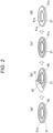
- an annular masking tape 40 is caused to adhere onto each of the raceway surface 31a of the stationary bearing ring 31 and the raceway surface 32a of the rotating bearing ring 32. It is to be noted that FIG. 2 shows only the raceway surface 31a of the stationary bearing ring 31 for convenience of explanation.
- the width of the masking tape 40 may equal to or slightly longer than a total length of the needle rollers 33.
- an entire surface of the raceway surface 31a including the portion covered with the masking tape 40 is uniformly coated with an oil repellent liquid 41.
- Examples of the method for applying the oil repellent liquid 41 include spray coating using a spray 42, roller coating, and the like.
- the oil repellent liquid 41 contains an oil repellent agent, a solvent, a binder, and the like.
- the oil repellent liquid 41 forms an oil repellent film 41a on the raceway surfaces 31a and 32a after drying, as will be described below.
- suitable oil repellent agent include fluorine-based surfactants, fluorine-based silane coupling agents, fluorine-based polymers, and the like.
- these may be dissolved in a solvent, or a binder may be used in combination.
- the oil repellent film 41a is formed on the raceway surface 31a. Drying may be performed at room temperature, but may be performed with heating as necessary.
- the stationary bearing ring 31 is prepared, and the entire surface of the raceway surface 31a is uniformly coated with the oil repellent liquid 41 with the sprayer 42, for example.
- the oil repellent film 41a is formed on the entire surface of the raceway surface 31a.
- the oil repellent film 41a formed on the entire surface of the raceway surface 31a is peeled off by rotating the bearing, and it is sufficient if the oil repellent agent or the like that is peeled off at that time does not act as a foreign substance and the hardness of the constituent components (oil repellent agent, etc.) of the oil repellent liquid 41 is sufficiently lower than the hardness of the bearing rings 31 and 32 and the needle rollers 33.
- suitable oil repellent agent for achieving the object described above include the fluorine-based surfactants, fluorine-based silane coupling agents, fluorine-based polymers, and the like described above.
- the thrust needle roller bearing is assembled using a cage incorporating needle rollers, the stationary bearing ring 31 with the oil repellent film 41a formed as described above, and the rotating bearing ring 32 with the oil repellent film 41a formed in the same manner. Then, a predetermined lubricating oil is applied to the needle rollers, and a predetermined load is applied to rotate the bearing.
- the thrust needle roller bearing 30 obtained as described above since the portions of the annular raceway surfaces 31a and 32a of the bearing rings 31 and 32 other than the portion in contact with the needle rollers 33 are subjected to the oil repellent treatment and thus have the oil repellent film 41a, even when the lubricating oil held between the raceway surfaces 31a and 32a and the needle rollers 33 tends to move to the outside of the bearing due to centrifugal force, for example, the lubricating oil can be blocked by the portions subjected to the oil repellent treatment (that is, the portions on which the oil repellent film 41a is formed), and prevented from moving further. Therefore, even in the thrust needle roller bearing 30 with a reduced amount of oil, a sufficient amount of oil is held, and seizure can be effectively prevented.
- both the radially outer portion and the radially inner portion from the portions of the raceway surfaces 31a and 32a in contact with the needle rollers 33 are subjected to the oil repellent treatment
- at least one of the radially outer portion and the radially inner portion may be subjected to the oil repellent treatment.
- the thrust needle roller bearing 30 As the thrust needle roller bearing 30 is rotated, the lubricating oil held between the raceway surfaces 31a and 32a and the needle rollers 33 is more likely to move more radially outward than radially inward due to centrifugal force, and accordingly, in order to effectively prevent the lubricating oil from flowing to the outside of the bearing, it is preferable that at least the radially outer side be subjected to the oil repellent treatment. However, in order to effectively prevent the lubricating oil from flowing to the radially inner side, it is more preferable that both the radially outer portion and the radially inner portion be subjected to the oil repellent treatment.
- the configuration of the thrust needle roller bearing 30 itself is not limited, and for example, the raceway surface of the needle rollers 33 may be crowned. Further, as described in JP2008-261476A , for example, the portion of the raceway surfaces 31a and 32a in contact with the needle rollers 33 may have a convex shape with a curved surface. Furthermore, flanges (collars) extending in an axial direction orthogonal to the raceway surfaces 31a and 32a may be provided on the outer diameter side of the bearing rings 31 and 32, and, particularly, providing the flange on the radially outer side of the rotating bearing ring 32 allows to more effectively prevent the lubricating oil from moving to the outside due to centrifugal force.
- the cage 34 may be formed by molding, combining, and caulking two plate materials to hold the needle rollers 33, or may be formed by molding one plate material in an M shape to hold the needle rollers 33 at a portion having an M-shaped cross section. Furthermore, the cage 34 may be made of steel or synthetic resin.
- the lubricating oil is also not particularly limited, and commonly used lubricating oil may be used.
- a thrust needle roller bearing having a bearing ring with an oil repellent film formed on a raceway surface was prepared, and as a Comparative Example product, a thrust needle roller bearing having a bearing ring of which raceway surface was not subjected to oil repellent treatment was prepared, and the seizure test was performed on each thrust needle roller bearing.
- Thrust needle roller bearings shown below were prepared.
- the cage was configured with two cage members formed in an annular plate shape and assembled integrally, by pressing a steel plate.
- the cage includes pockets formed radially in the circumferential direction of a main body of one cage member, and pockets formed radially in the circumferential direction of a main body of the other cage member, and the needle rollers are interposed between the two pockets so as to be rollably held.
- a bearing ring that is formed in an annular shape and has no flange, collar, or the like was used for the bearing ring.
- the raceway surface of the bearing ring was subjected to a predetermined oil repellent treatment.
- an oil repellent liquid A containing polytetrafluoroethylene (PTFE) and a cellulose-based binder was uniformly applied to the entire surface of the bearing ring with a spray (Section (b) of FIG. 3 ).
- the oil repellent liquid A was NEW TFE COAT (manufactured by Fine Chemical Japan Co., Ltd.).
- drying is performed at room temperature (25°C) for 2 hours (Section (c) of FIG. 3 ).
- the oil repellent film formed on the entire surface of the raceway surface of the bearing ring a portion in contact with the needle rollers was removed by the following procedure (Section (d) of FIG. 3 ).
- the test bearing was installed in a test machine housing, and 1 ml of additive-free ISO-VG32 turbine oil was applied to the test bearing. Then, the test machine housing provided with the test bearing was installed in the test machine. Then, a load of 150 kgf was applied, and a rotational speed was 3,000 rpm for 10 seconds. After stopping the rotation, the test bearing was taken out and washed with heptane.
- the thrust needle roller bearings as the Example product and the Comparative Example product were incorporated into the housing, and then a load was applied to start rotation.
- the test condition is as follows, and reproduces an environment in which the supply of lubricating oil is interrupted. After the start of rotation, when the bearing torque exceeded five times the initial value, it was determined that "seizure occurred", and the test was stopped.
- FIG. 4 shows the test results of thrust needle roller bearings according to the Example product and the Comparative Example product in Example 1. It is to be noted that, in FIG. 4 , the cumulative failure probability (%) versus lifespan (period of time: hours) is plotted for each of the Example product and the Comparative Example product (Weibull plot).
- L10 It represents the period of time (or total number of revolutions, etc.) during which 90% of the bearings can rotate without causing damage due to rolling fatigue, and ISO defines L10 as the "rated lifespan of rolling bearings".
- L50 It represents the period of time (or total number of revolutions, etc.) during which 50% of the bearings can rotate without causing damage due to rolling fatigue. L10 may decrease in accuracy when there is little lifespan data or when the lifespan data varies greatly, and in this case, L50 data may be used to compare lifespans.
- Example that is, 3.9
- Comparative Example the Example product subjected to the predetermined oil repellent treatment showed a lifespan ten times longer than the Comparative Example product not subjected to the oil repellent treatment.
- a thrust needle roller bearing having a bearing ring with an oil repellent film formed on the raceway surface was prepared by a method different from that of Example 1, and as a Comparative Example product, a thrust needle roller bearing having a bearing ring of which raceway surface was not subjected to oil repellent treatment was prepared, and the seizure test was performed on each thrust needle roller bearing.
- the raceway surface of the bearing ring was subjected to oil repellent treatment according to the processes shown in FIG. 2 .
- a masking tape was caused to adhere onto the ring with a width of 6.0 mm with respect to the total length of 5.6 mm of the needle roller (Section (a) of FIG. 2 ).
- the entire surface of the raceway surface was uniformly coated with an oil repellent liquid (Section (b) of FIG. 2 ), and then the applied oil repellent liquid was dried at room temperature (25°C) for 2 hours (Section (c) of FIG. 2 ).
- the adhered masking tape was peeled off (Section (d) of FIG. 2 ).
- Example product a thrust needle roller bearing incorporating a bearing ring with an oil repellent film formed on the raceway surface by using the oil repellent liquid A and the method described above was prepared, and as a Comparative Example product, a thrust needle roller bearing incorporating a bearing ring of which raceway surface was not subjected to oil repellent treatment was prepared. Then, the seizure test was performed under the same conditions as in Example 1.
- FIG. 5 shows the test results of thrust needle roller bearings according to the Example product and the Comparative Example product in Example 2. It is to be noted that, in FIG. 5 as well as in FIG. 4 , the cumulative failure probability (%) versus lifespan (period of time: hours) is plotted for each of the Example product and the Comparative Example product (Weibull plot).
- Example 1 As shown in FIG. 5 , as in Example 1, according to a comparison of the "e” value with oil repellent treatment (Example), that is, 0.9, and the “e” value without oil repellent treatment (Comparative Example), that is, 0.8, the difference in the degree of variation in the lifespan data is small, that is, the inclinations of the Weibull slopes are similar and do not cross, and accordingly, the lifespan can be compared using the L10 data in this test example as well.
- Example that is, 0.6
- Comparative Example that is, 0.2
- Example product subjected to the predetermined oil repellent treatment showed about three times the lifespan of the Comparative Example product not subjected to the oil repellent treatment.
- Example 2 differs from Example 1 in the method of removing the oil repellent film from the portion of the raceway surface in contact with the needle roller. From the results of Examples 1 and 2, in the seizure test at room temperature (25°C) on the oil repellent film using the oil repellent liquid A, an extremely excellent lifespan was observed regardless of the method of removal.
- Thrust needle roller bearings each having a bearing ring with an oil repellent film formed on the raceway surface were prepared in the same manner as in Example 1 above, and the seizure test was performed on each thrust needle roller bearing. However, in Example 3, oil repellent films with various film thicknesses were formed on the bearing rings by changing the number of oil repellent treatments.
- the raceway surface of the bearing ring was subjected to oil repellent treatment according to the processes shown in FIG. 2 .
- a masking tape was caused to adhere onto the ring with a width of 6.0 mm with respect to the total length of 5.6 mm of the needle roller (Section (a) of FIG. 2 ).
- an oil repellent liquid B containing polytetrafluoroethylene (PTFE) and a thermosetting resin was uniformly applied to the entire surface of the bearing ring with a spray (Section (b) of FIG. 2 ) and dried at room temperature (25°C) for 2 hours (Section (c) of FIG. 2 ).
- the oil repellent liquid B was FINE HEAT RESISTANT TFE COAT (manufactured by Fine Chemical Japan Co., Ltd.). Then, the thermosetting resin was heated at 200°C for 20 minutes so as to be cured. Then, the adhered masking tape was peeled off (Section (d) of FIG. 2 ).
- Example 3 As a result of measuring the film thickness at four points on the test material subjected to oil repellent treatment one time, the average film thickness was about 2.0 ⁇ m. In addition, as a result of similarly measuring the film thickness at four points on the test material subjected to oil repellent treatment four times, the average film thickness was about 9.3 ⁇ m. In addition, in Example 3, six test materials subjected to oil repellent treatment one time and six test materials subjected to oil repellent treatment four times were prepared, respectively, and these test materials were used to prepare bearings.
- the seizure test was performed under the test condition shown below by using the same method as in Example 1 described above.
- the difference from Examples 1 and 2 described above lies in the test temperature, and in Example 3, the test temperature was set to 100°C.
- FIG. 6 is a graph showing a lifespan of each bearing.
- the numerical values described above each bar graph are the lifespan (hours) of each bearing.
- Bearing Nos. 7 to 12 subjected to oil repellent treatment four times had a longer lifespan than Bearing Nos. 1 to 6 subjected to oil repellent treatment one time.
- Example 3 the oil repellent liquid was different from those of Examples 1 and 2, and the temperature of the seizure test was set to 100°C, so it can be said that the seizure test was performed under severe conditions. Even under such conditions, when the oil repellent liquid B was used, an excellent lifespan was observed.
- Example 4 For the bearing rings with the oil repellent films formed on the raceway surfaces in the same manner as in Example 2 described above, a contact angle with turbine oil was measured, thrust needle roller bearings having the obtained bearing rings were prepared, and the seizure test was performed on each thrust needle roller bearing. However, in Example 4, oil repellent films with various different components were formed on the bearing ring by changing the type of oil repellent liquid.
- Example 2 Using the same thrust needle roller bearing as in Example 1, the raceway surface of the bearing ring was subjected to oil repellent treatment according to the processes shown in FIG. 2 .
- the types of oil repellent liquids used are shown below.
- the test material using the oil repellent liquid A was not subjected to the baking treatment, the test material using the oil repellent liquid B was heated at 200°C for 20 minutes, and the test material using an oil repellent liquid C was heated at 100°C for 25 minutes.
- Example 4 five test materials subjected to oil repellent treatment were prepared for each type of oil repellent liquid, and nine test materials not subjected to oil repellent treatment were prepared.
- the contact angle was measured and the average contact angle for each oil repellent liquid was calculated.
- the contact angles with respect to nine test materials were measured and the average contact angle was calculated.
- the average contact angle is a value obtained by measuring the contact angle zero (0) seconds after droplets of additive-free VG32 turbine oil (VG32 turbine oil) were landed on the surface subjected to oil repellent treatment, repeating this measurement three times, and calculating the average.
- the types of oil repellent liquids and average contact angles are shown below.
- Test materials (bearing rings) using various oil repellent liquids were assembled only on the stationary ring side, five thrust needle roller bearings were prepared for each oil repellent liquid, nine thrust needle roller bearings were prepared using test materials (bearing rings) not subjected to oil repellent treatment, and the seizure test was performed on each bearing using the same method and condition as in Example 3 described above.
- FIG. 7 is a graph showing an average lifespan of each test material, with the average lifespan plotted on the vertical axis and an average contact angle with VG32 turbine oil plotted on the horizontal axis.
- Oil Repellent Liquid A indicates the average lifespan of five bearings using each oil repellent liquid.
- Oil Repellent Treatment shown in FIG. 7 indicates the average lifespan of nine bearings prepared using test materials not subjected to oil repellent treatment. As shown in FIG. 7 , the lifespan of the bearing using the test material subjected to oil repellent treatment with the oil repellent liquid A is shorter than that of the bearing not subjected to oil repellent treatment.
- baking treatment was performed at 100°C or 200°C in order to cure the resin in the oil repellent liquid, but when forming the oil repellent film using the oil repellent liquid A, the baking treatment is not required, and the amount of CO 2 emitted during the formation of the oil repellent film can be reduced. Therefore, it is preferable to appropriately select the type of oil repellent liquid to use according to the environment in which the bearing is used.
Landscapes
- Engineering & Computer Science (AREA)
- General Engineering & Computer Science (AREA)
- Mechanical Engineering (AREA)
- Manufacturing & Machinery (AREA)
- Rolling Contact Bearings (AREA)
Abstract
Description
- The present invention relates to a thrust needle roller bearing.
- In the automobile field, for the improved fuel efficiency of automobiles, the electrification, miniaturization, and high speed operation are in progress. Along with this, in bearings, lubricating oil instead of grease is charged, or lubricating oil is applied to rolling elements and raceway surfaces to reduce torque. Furthermore, in order to reduce loss due to lubricating oil, efforts are made to reduce the amount of lubricating oil.
- However, as the amount of lubricating oil decreases, there is a concern that damage such as seizure occurs due to a lack of lubricating oil. When the bearing is rotated at high speed, the lubricating oil lubricating the rolling elements and the raceway surface is moved to the outside due to centrifugal force. Therefore, when the supply is interrupted or the amount of supplied oil is small, the amount of lubricating oil gradually decreases, eventually causing seizure.
- Therefore, for example,
Patent Literature 1 discloses a technique relating to a bearing device in which, on an outer peripheral surface of an inner ring and an inner peripheral surface of an outer ring, an oil repellent coating is formed in a first region P1 and a second region P2 except for rotating raceway grooves and stationary raceway grooves. - Patent Literature:
JP2017-125550A - Meanwhile, in addition to being applied to transmissions of automobiles and industrial construction machinery, the thrust needle roller bearings are widely used in other rotating equipment and suitably used for highspeed rotation applications. However, because sealing members such as seals cannot be used in the thrust needle roller bearings due to structural restrictions, and centrifugal force tends to cause lubricating oil to leak out of the bearings, there is a problem that seizure is particularly likely to occur in an environment where the amount of lubricating oil is small.
- Accordingly, an object of the present invention is to prevent seizure in a thrust needle roller bearing, by holding an amount of lubricating oil even in an environment where the amount of lubricating oil is small.
- The object of the present invention is achieved by the following configuration (1) according to a thrust needle roller bearing.
- (1) The thrust needle roller bearing including a plurality of needle rollers, a bearing ring having an annular raceway surface on which the needle rollers roll, and a cage that rollably holds the needle rollers,
in which a portion of the raceway surface other than a portion in contact with the needle rollers is subjected to oil repellent treatment.
Further, preferred embodiments of the present invention according to a thrust needle roller bearing relate to the following (2) and (3). - (2) The thrust needle roller bearing according to (1) described above, in which a radially outer portion from the portion of the raceway surface in contact with the needle rollers is subjected to oil repellent treatment.
- (3) The thrust needle roller bearing according to (1) or (2) described above, in which a radially inner portion from the portion of the raceway surface in contact with the needle rollers is subjected to oil repellent treatment.
- According to the thrust needle roller bearing of the present invention, since the portion of the annular raceway surface of the bearing ring other than the portion in contact with the needle rollers is subjected to oil repellent treatment, even when the lubricating oil held between the raceway surface and the needle rollers tends to move to the outside of the bearing due to centrifugal force, the lubricating oil can be blocked by the portion subjected to the oil repellent treatment, and prevented from moving further. Therefore, even in a thrust needle roller bearing with a reduced amount of oil, a sufficient amount of oil is held, and seizure can be effectively prevented.
-
-
FIG. 1 is a partially cutaway perspective view of a thrust needle roller bearing. -
FIG. 2 is a diagram illustrating a method for subjecting oil repellent treatment to a raceway surface of a bearing ring. -
FIG. 3 is a diagram illustrating another method for subjecting the oil repellent treatment to the raceway surface of the bearing ring. -
FIG. 4 is a graph showing a result of plotting cumulative failure probability (%) versus lifespan (hours) for an Example product and a Comparative Example product shown in Example 1. -
FIG. 5 is a graph showing a result of plotting cumulative failure probability (%) versus lifespan (hours) for an Example product and a Comparative Example product shown in Example 2. -
FIG. 6 is a graph showing a lifespan of each bearing. -
FIG. 7 is a graph showing an average lifespan of each test material, with the average lifespan plotted on a vertical axis and an average contact angle with VG32 turbine oil plotted on a horizontal axis. - Hereinafter, The present invention will be described in detail with reference to the drawings.
-
FIG. 1 is a partially cutaway perspective view of a structure of a thrust needle roller bearing. As shown in the drawing, a thrust needle roller bearing 30 includes an annularstationary bearing ring 31 and a rotating bearingring 32 facing each other, a plurality ofneedle rollers 33 rollably (freely rollably) arranged between these bearing rings, and acage 34 that rollably (freely rollably) holds theneedle rollers 33. - In the present embodiment, in at least one, or preferably, in both of a
raceway surface 31a of thestationary bearing ring 31 and araceway surface 32a of the rotating bearingring 32, portions of theraceway surfaces needle rollers 33 are subjected to oil repellent treatment (not shown). More specifically, in the present embodiment, both a radially outer portion and a radially inner portion from the portions of theraceway surfaces needle rollers 33 are subjected to the oil repellent treatment. - As a method of the oil repellent treatment, for example, the processes shown in Section (a) to Section (d) of
FIG. 2 are performed. - First, as shown in Section (a) of
FIG. 2 , anannular masking tape 40 is caused to adhere onto each of theraceway surface 31a of thestationary bearing ring 31 and theraceway surface 32a of the rotatingbearing ring 32. It is to be noted thatFIG. 2 shows only theraceway surface 31a of the stationary bearingring 31 for convenience of explanation. The width of themasking tape 40 may equal to or slightly longer than a total length of theneedle rollers 33. By causing themasking tape 40 to adhere, only an outer peripheral portion (the radially outer side from the portion of theraceway surface 31a in contact with the needle rollers 33) and an inner peripheral portion (the radially inner side from the portion of theraceway surface 31a in contact with the needle rollers 33) of theraceway surface 31a are exposed. - Next, as shown in Section (b) of
FIG. 2 , an entire surface of theraceway surface 31a including the portion covered with themasking tape 40 is uniformly coated with anoil repellent liquid 41. Examples of the method for applying theoil repellent liquid 41 include spray coating using aspray 42, roller coating, and the like. - The
oil repellent liquid 41 contains an oil repellent agent, a solvent, a binder, and the like. Theoil repellent liquid 41 forms anoil repellent film 41a on theraceway surfaces - Subsequently, as shown in Section (c) of
FIG. 2 , by drying the appliedoil repellent liquid 41, theoil repellent film 41a is formed on theraceway surface 31a. Drying may be performed at room temperature, but may be performed with heating as necessary. - After drying, as shown in Section (d) of
FIG. 2 , by peeling off the adheredmasking tape 40, theoil repellent film 41a remains on each of the outer peripheral portion and the inner peripheral portion of theraceway surface 31a, and thestationary bearing ring 31 is obtained, in which theraceway surface 31a is exposed at a radial center portion corresponding to the width of themasking tape 40 interposed between the two peripheral portions. - As another method of the oil repellent treatment, for example, the processes shown in Section (a) to Section(d) of
FIG. 3 are performed. - First, as shown in Section (a) and Section(b) of
FIG. 3 , thestationary bearing ring 31 is prepared, and the entire surface of theraceway surface 31a is uniformly coated with theoil repellent liquid 41 with thesprayer 42, for example. - Next, as shown in Section (c) of
FIG. 3 , by drying the appliedoil repellent liquid 41, theoil repellent film 41a is formed on the entire surface of theraceway surface 31a. - In addition, regarding the
oil repellent film 41a formed on the entire surface of theraceway surface 31a, as will be described below, theoil repellent film 41a on the portion of theraceway surface 31a in contact with the needle rollers is peeled off by rotating the bearing, and it is sufficient if the oil repellent agent or the like that is peeled off at that time does not act as a foreign substance and the hardness of the constituent components (oil repellent agent, etc.) of theoil repellent liquid 41 is sufficiently lower than the hardness of thebearing rings needle rollers 33. Examples of the suitable oil repellent agent for achieving the object described above include the fluorine-based surfactants, fluorine-based silane coupling agents, fluorine-based polymers, and the like described above. - Subsequently, although not illustrated, the thrust needle roller bearing is assembled using a cage incorporating needle rollers, the
stationary bearing ring 31 with theoil repellent film 41a formed as described above, and the rotating bearingring 32 with theoil repellent film 41a formed in the same manner. Then, a predetermined lubricating oil is applied to the needle rollers, and a predetermined load is applied to rotate the bearing. - After a predetermined time elapses, the rotation is stopped and then, by washing the bearing with oil, a bearing ring is obtained, in which the
oil repellent film 41a is not formed on the portion of the raceway surface (theraceway surface 31a of thestationary bearing ring 31 inFIG. 3 ) in contact with the needle rollers, and theoil repellent film 41a is formed on each of the outer peripheral portion and the inner peripheral portion of the raceway surface, as shown in Section (d) ofFIG. 3 . - The examples of the method of the oil repellent treatment have been described above.
- In the thrust needle roller bearing 30 obtained as described above, since the portions of the
annular raceway surfaces bearing rings needle rollers 33 are subjected to the oil repellent treatment and thus have theoil repellent film 41a, even when the lubricating oil held between theraceway surfaces needle rollers 33 tends to move to the outside of the bearing due to centrifugal force, for example, the lubricating oil can be blocked by the portions subjected to the oil repellent treatment (that is, the portions on which theoil repellent film 41a is formed), and prevented from moving further. Therefore, even in the thrust needle roller bearing 30 with a reduced amount of oil, a sufficient amount of oil is held, and seizure can be effectively prevented. - In the embodiment described above, although it is illustrated that both the radially outer portion and the radially inner portion from the portions of the raceway surfaces 31a and 32a in contact with the
needle rollers 33 are subjected to the oil repellent treatment, at least one of the radially outer portion and the radially inner portion may be subjected to the oil repellent treatment. - In addition, as the thrust
needle roller bearing 30 is rotated, the lubricating oil held between the raceway surfaces 31a and 32a and theneedle rollers 33 is more likely to move more radially outward than radially inward due to centrifugal force, and accordingly, in order to effectively prevent the lubricating oil from flowing to the outside of the bearing, it is preferable that at least the radially outer side be subjected to the oil repellent treatment. However, in order to effectively prevent the lubricating oil from flowing to the radially inner side, it is more preferable that both the radially outer portion and the radially inner portion be subjected to the oil repellent treatment. - Meanwhile, the configuration of the thrust
needle roller bearing 30 itself is not limited, and for example, the raceway surface of theneedle rollers 33 may be crowned. Further, as described inJP2008-261476A needle rollers 33 may have a convex shape with a curved surface. Furthermore, flanges (collars) extending in an axial direction orthogonal to the raceway surfaces 31a and 32a may be provided on the outer diameter side of the bearing rings 31 and 32, and, particularly, providing the flange on the radially outer side of therotating bearing ring 32 allows to more effectively prevent the lubricating oil from moving to the outside due to centrifugal force. - Further, the
cage 34 may be formed by molding, combining, and caulking two plate materials to hold theneedle rollers 33, or may be formed by molding one plate material in an M shape to hold theneedle rollers 33 at a portion having an M-shaped cross section. Furthermore, thecage 34 may be made of steel or synthetic resin. - The lubricating oil is also not particularly limited, and commonly used lubricating oil may be used.
- Hereinafter, the present invention will be described in more detail with reference to Examples, but the present invention is not limited thereto.
- As an Example product, a thrust needle roller bearing having a bearing ring with an oil repellent film formed on a raceway surface was prepared, and as a Comparative Example product, a thrust needle roller bearing having a bearing ring of which raceway surface was not subjected to oil repellent treatment was prepared, and the seizure test was performed on each thrust needle roller bearing.
- Thrust needle roller bearings shown below were prepared.
- · Cage and needle rollers: FNTA-2542 (manufactured by NSK Ltd.)
- · Bearing ring: FTRA-2542 (manufactured by NSK Ltd.)
- · Bearing ring: 2 pieces
- · Bearing ring material: SK85 (carbon tool steel material: JIS standard)
- · Cage material: SPCC (cold-rolled steel plate)
- · Needle roller material: SUJ2 (high carbon chromium bearing steel)
- The cage was configured with two cage members formed in an annular plate shape and assembled integrally, by pressing a steel plate. In addition, the cage includes pockets formed radially in the circumferential direction of a main body of one cage member, and pockets formed radially in the circumferential direction of a main body of the other cage member, and the needle rollers are interposed between the two pockets so as to be rollably held. In addition, for the bearing ring, a bearing ring that is formed in an annular shape and has no flange, collar, or the like was used.
- Then, according to the process shown in
FIG. 3 , the raceway surface of the bearing ring was subjected to a predetermined oil repellent treatment. First, after degreasing the bearing ring with an organic solvent, an oil repellent liquid A containing polytetrafluoroethylene (PTFE) and a cellulose-based binder was uniformly applied to the entire surface of the bearing ring with a spray (Section (b) ofFIG. 3 ). The oil repellent liquid A was NEW TFE COAT (manufactured by Fine Chemical Japan Co., Ltd.). Then, drying is performed at room temperature (25°C) for 2 hours (Section (c) ofFIG. 3 ). Then, of the oil repellent film formed on the entire surface of the raceway surface of the bearing ring, a portion in contact with the needle rollers was removed by the following procedure (Section (d) ofFIG. 3 ). - First, using the bearing ring and the cage incorporating the needle rollers as a test bearing, the test bearing was installed in a test machine housing, and 1 ml of additive-free ISO-VG32 turbine oil was applied to the test bearing. Then, the test machine housing provided with the test bearing was installed in the test machine. Then, a load of 150 kgf was applied, and a rotational speed was 3,000 rpm for 10 seconds. After stopping the rotation, the test bearing was taken out and washed with heptane.
- After degreasing and washing with heptane, the thrust needle roller bearings as the Example product and the Comparative Example product were incorporated into the housing, and then a load was applied to start rotation. The test condition is as follows, and reproduces an environment in which the supply of lubricating oil is interrupted. After the start of rotation, when the bearing torque exceeded five times the initial value, it was determined that "seizure occurred", and the test was stopped.
-
- · Lubricating oil type: additive-free ISO-VG32 turbine oil
- · Amount of lubricating oil: 1 ml (initial supply only)
- · Load: 150 kgf
- · Rotational speed: 3,000 rpm
- · Temperature: Room temperature (25°C)
-
FIG. 4 shows the test results of thrust needle roller bearings according to the Example product and the Comparative Example product in Example 1. It is to be noted that, inFIG. 4 , the cumulative failure probability (%) versus lifespan (period of time: hours) is plotted for each of the Example product and the Comparative Example product (Weibull plot). - In
FIG. 4 , the data indicated by "•" represents that the oil repellent treatment is applied (Example), and the data indicated by "□" represents that the oil repellent treatment is not applied (Comparative Example). - In addition, in
FIG. 4 , "→" shown on the right side of a part of the plot of "•" or "□" represents that seizure did not occur for the corresponding period of time, so the test was interrupted (discontinued) for the period of time. - "e": It is an index representing the variation in lifespan, and as the variation in the lifespan data decreases, this value increases.
- "L10": It represents the period of time (or total number of revolutions, etc.) during which 90% of the bearings can rotate without causing damage due to rolling fatigue, and ISO defines L10 as the "rated lifespan of rolling bearings".
- "L50": It represents the period of time (or total number of revolutions, etc.) during which 50% of the bearings can rotate without causing damage due to rolling fatigue. L10 may decrease in accuracy when there is little lifespan data or when the lifespan data varies greatly, and in this case, L50 data may be used to compare lifespans.
- As shown in
FIG. 4 , according to a comparison of the "e" value with oil repellent treatment (Example), that is, 1.1, and the "e" value without oil repellent treatment (Comparative Example), that is, 0.8, the difference in the degree of variation in the lifespan data is small, that is, the inclinations of the Weibull slopes are similar and do not cross, and accordingly, the lifespan can be compared using the L10 data in this test example. - Then, according to a comparison of the "L10" value with oil repellent treatment (Example), that is, 3.9, and the "L10" value without oil repellent treatment (Comparative Example), that is, 0.2, the Example product subjected to the predetermined oil repellent treatment showed a lifespan ten times longer than the Comparative Example product not subjected to the oil repellent treatment.
- As an Example product, a thrust needle roller bearing having a bearing ring with an oil repellent film formed on the raceway surface was prepared by a method different from that of Example 1, and as a Comparative Example product, a thrust needle roller bearing having a bearing ring of which raceway surface was not subjected to oil repellent treatment was prepared, and the seizure test was performed on each thrust needle roller bearing.
- Using the same thrust needle roller bearing as in Example 1, the raceway surface of the bearing ring was subjected to oil repellent treatment according to the processes shown in
FIG. 2 . First, a masking tape was caused to adhere onto the ring with a width of 6.0 mm with respect to the total length of 5.6 mm of the needle roller (Section (a) ofFIG. 2 ). Next, the entire surface of the raceway surface was uniformly coated with an oil repellent liquid (Section (b) ofFIG. 2 ), and then the applied oil repellent liquid was dried at room temperature (25°C) for 2 hours (Section (c) ofFIG. 2 ). Then, after the oil repellent liquid was dried, the adhered masking tape was peeled off (Section (d) ofFIG. 2 ). - As an Example product, a thrust needle roller bearing incorporating a bearing ring with an oil repellent film formed on the raceway surface by using the oil repellent liquid A and the method described above was prepared, and as a Comparative Example product, a thrust needle roller bearing incorporating a bearing ring of which raceway surface was not subjected to oil repellent treatment was prepared. Then, the seizure test was performed under the same conditions as in Example 1.
-
FIG. 5 shows the test results of thrust needle roller bearings according to the Example product and the Comparative Example product in Example 2. It is to be noted that, inFIG. 5 as well as inFIG. 4 , the cumulative failure probability (%) versus lifespan (period of time: hours) is plotted for each of the Example product and the Comparative Example product (Weibull plot). - In addition, the meanings of "•", "□", "→", "e", "L10" and "L50" in
FIG. 5 are the same as those described in Example 1. - As shown in
FIG. 5 , as in Example 1, according to a comparison of the "e" value with oil repellent treatment (Example), that is, 0.9, and the "e" value without oil repellent treatment (Comparative Example), that is, 0.8, the difference in the degree of variation in the lifespan data is small, that is, the inclinations of the Weibull slopes are similar and do not cross, and accordingly, the lifespan can be compared using the L10 data in this test example as well. - Then, according to a comparison of the "L10" value with oil repellent treatment (Example), that is, 0.6, and the "L10" value without oil repellent treatment (Comparative Example), that is, 0.2, the Example product subjected to the predetermined oil repellent treatment showed about three times the lifespan of the Comparative Example product not subjected to the oil repellent treatment.
- As described above, Example 2 differs from Example 1 in the method of removing the oil repellent film from the portion of the raceway surface in contact with the needle roller. From the results of Examples 1 and 2, in the seizure test at room temperature (25°C) on the oil repellent film using the oil repellent liquid A, an extremely excellent lifespan was observed regardless of the method of removal.
- Thrust needle roller bearings each having a bearing ring with an oil repellent film formed on the raceway surface were prepared in the same manner as in Example 1 above, and the seizure test was performed on each thrust needle roller bearing. However, in Example 3, oil repellent films with various film thicknesses were formed on the bearing rings by changing the number of oil repellent treatments.
- Using the same thrust needle roller bearing as in Example 1, the raceway surface of the bearing ring was subjected to oil repellent treatment according to the processes shown in
FIG. 2 . First, after degreasing the bearing ring with an organic solvent, a masking tape was caused to adhere onto the ring with a width of 6.0 mm with respect to the total length of 5.6 mm of the needle roller (Section (a) ofFIG. 2 ). Next, an oil repellent liquid B containing polytetrafluoroethylene (PTFE) and a thermosetting resin was uniformly applied to the entire surface of the bearing ring with a spray (Section (b) ofFIG. 2 ) and dried at room temperature (25°C) for 2 hours (Section (c) ofFIG. 2 ). The oil repellent liquid B was FINE HEAT RESISTANT TFE COAT (manufactured by Fine Chemical Japan Co., Ltd.). Then, the thermosetting resin was heated at 200°C for 20 minutes so as to be cured. Then, the adhered masking tape was peeled off (Section (d) ofFIG. 2 ). - For the test material to be subjected to oil repellent treatment four times, in the same manner as the above method, the process of applying the oil repellent liquid to the entire surface of the bearing ring to which the masking tape was attached and the process of drying and heating the applied oil repellent liquid were repeated four times in total, and then the masking tape was peeled off (Section (d) of
FIG. 2 ). - As a result of measuring the film thickness at four points on the test material subjected to oil repellent treatment one time, the average film thickness was about 2.0 µm. In addition, as a result of similarly measuring the film thickness at four points on the test material subjected to oil repellent treatment four times, the average film thickness was about 9.3 µm. In addition, in Example 3, six test materials subjected to oil repellent treatment one time and six test materials subjected to oil repellent treatment four times were prepared, respectively, and these test materials were used to prepare bearings.
- With the bearings using the test material subjected to oil repellent treatment one time (Bearing Nos. 1 to 6) and the bearings using the test material subjected to oil repellent treatment four times (Bearing Nos. 7 to 12), the seizure test was performed under the test condition shown below by using the same method as in Example 1 described above. In addition, in the test condition shown below, the difference from Examples 1 and 2 described above lies in the test temperature, and in Example 3, the test temperature was set to 100°C.
-
- · Lubricating oil type: additive-free ISO-VG32 turbine oil
- · Amount of lubricating oil: 1 ml (initial supply only)
- · Load: 150 kgf
- · Rotational speed: 3,000 rpm
- · Temperature: 100°C (housing heating)
-
FIG. 6 is a graph showing a lifespan of each bearing. The numerical values described above each bar graph are the lifespan (hours) of each bearing. As shown inFIG. 6 , Bearing Nos. 7 to 12 subjected to oil repellent treatment four times had a longer lifespan than Bearing Nos. 1 to 6 subjected to oil repellent treatment one time. - In Example 3 above, the oil repellent liquid was different from those of Examples 1 and 2, and the temperature of the seizure test was set to 100°C, so it can be said that the seizure test was performed under severe conditions. Even under such conditions, when the oil repellent liquid B was used, an excellent lifespan was observed.
- For the bearing rings with the oil repellent films formed on the raceway surfaces in the same manner as in Example 2 described above, a contact angle with turbine oil was measured, thrust needle roller bearings having the obtained bearing rings were prepared, and the seizure test was performed on each thrust needle roller bearing. However, in Example 4, oil repellent films with various different components were formed on the bearing ring by changing the type of oil repellent liquid.
- Using the same thrust needle roller bearing as in Example 1, the raceway surface of the bearing ring was subjected to oil repellent treatment according to the processes shown in
FIG. 2 . The types of oil repellent liquids used are shown below. In addition, when forming the oil repellent film, the test material using the oil repellent liquid A was not subjected to the baking treatment, the test material using the oil repellent liquid B was heated at 200°C for 20 minutes, and the test material using an oil repellent liquid C was heated at 100°C for 25 minutes. Further, in Example 4, five test materials subjected to oil repellent treatment were prepared for each type of oil repellent liquid, and nine test materials not subjected to oil repellent treatment were prepared. -
- Oil repellent liquid A: NEW TFE COAT (manufactured by Fine Chemical Japan Co., Ltd.)
- Oil-repellent liquid B: FINE HEAT RESISTANT TFE COAT (manufactured by Fine Chemical Japan Co., Ltd.)
- Oil-repellent liquid C: Novec 1720 (manufactured by 3M Japan Limited)
- By dropping additive-free VG32 turbine oil (VG32 turbine oil) onto the surface of each of the obtained test materials that was subjected to oil repellent treatment, the contact angle was measured and the average contact angle for each oil repellent liquid was calculated. Likewise, by dropping VG32 turbine oil on the raceway surfaces of test materials (SK85 discs) that were not subjected to oil repellent treatment, the contact angles with respect to nine test materials were measured and the average contact angle was calculated. In addition, the average contact angle is a value obtained by measuring the contact angle zero (0) seconds after droplets of additive-free VG32 turbine oil (VG32 turbine oil) were landed on the surface subjected to oil repellent treatment, repeating this measurement three times, and calculating the average. The types of oil repellent liquids and average contact angles are shown below.
-
- Test material using oil repellent liquid A: 33.7°
- Test material using oil repellent liquid B: 44.9°
- Test material using oil repellent liquid C: 70.5°
- Test material not subjected to oil repellent treatment: 16.0°
- Comparing the average contact angles described above, regardless of the type of oil repellent liquid, the test material immediately after the oil repellent treatment had a larger average contact angle than the test material not subjected to the oil repellent treatment, indicating that excellent oil repellency performance was obtained.
- Test materials (bearing rings) using various oil repellent liquids were assembled only on the stationary ring side, five thrust needle roller bearings were prepared for each oil repellent liquid, nine thrust needle roller bearings were prepared using test materials (bearing rings) not subjected to oil repellent treatment, and the seizure test was performed on each bearing using the same method and condition as in Example 3 described above.
-
FIG. 7 is a graph showing an average lifespan of each test material, with the average lifespan plotted on the vertical axis and an average contact angle with VG32 turbine oil plotted on the horizontal axis. In addition, "Oil Repellent Liquid A", "Oil Repellent Liquid B", and "Oil Repellent Liquid C" shown inFIG. 7 indicate the average lifespan of five bearings using each oil repellent liquid. "Without Oil Repellent Treatment" shown inFIG. 7 indicates the average lifespan of nine bearings prepared using test materials not subjected to oil repellent treatment. As shown inFIG. 7 , the lifespan of the bearing using the test material subjected to oil repellent treatment with the oil repellent liquid A is shorter than that of the bearing not subjected to oil repellent treatment. It is considered that this is because the heat resistance of the components of the oil repellent liquid A is low. On the other hand, the bearings using test materials subjected to oil repellent treatment with the oil repellent liquid B and the oil repellent liquid C had a significantly longer lifespan than the bearings not subj ected to oil repellent treatment. From this result, it was shown that the oil repellent liquid B and the oil repellent liquid C are excellent in heat resistance, and can maintain an excellent oil repellent effect even when the temperature of the seizure test is set to 100°C. - Further, when forming the oil repellent film using the oil repellent liquid B and the oil repellent liquid C, baking treatment was performed at 100°C or 200°C in order to cure the resin in the oil repellent liquid, but when forming the oil repellent film using the oil repellent liquid A, the baking treatment is not required, and the amount of CO2 emitted during the formation of the oil repellent film can be reduced. Therefore, it is preferable to appropriately select the type of oil repellent liquid to use according to the environment in which the bearing is used.
- In addition, as shown in
FIG. 7 , when the seizure test was performed at 100°C, comparing the oil repellent liquid B and oil repellent liquid C with heat resistance showed that the lifespan increases as the average contact angle increases. - Although various embodiments have been described above with reference to the drawings, it goes without saying that the present invention is not limited to such examples. It will be apparent that those skilled in the art, within the scope described in the claims, can come up with various types of modification examples, or modifications, which are naturally within the technical scope of the present invention. In addition, the components in the embodiment described above may be freely combined without departing from the spirit of the invention.
- Note that this application is based on a Japanese Patent Application (
Japanese Patent Application No. 2021-025449) filed on February 19, 2021 Japanese Patent Application No. 2022-010302) filed on January 26, 2022 -
- 30: thrust needle roller bearing
- 31: stationary bearing ring
- 31a: raceway surface
- 32: rotating bearing ring
- 32a: raceway surface
- 33: needle roller
- 34: cage
- 40: masking tape
- 41: oil repellent liquid
- 41a: oil repellent film
- 42: spray
Claims (3)
- A thrust needle roller bearing comprising:a plurality of needle rollers;a bearing ring having an annular raceway surface on which the needle rollers roll; anda cage that rollably holds the needle rollers, whereina portion of the raceway surface other than a portion in contact with the needle rollers is subjected to oil repellent treatment.
- The thrust needle roller bearing according to claim 1, wherein a radially outer portion from the portion of the raceway surface in contact with the needle rollers is subjected to oil repellent treatment.
- The thrust needle roller bearing according to claim 1 or 2, wherein a radially inner portion from the portion of the raceway surface in contact with the needle rollers is subjected to oil repellent treatment.
Applications Claiming Priority (3)
| Application Number | Priority Date | Filing Date | Title |
|---|---|---|---|
| JP2021025449 | 2021-02-19 | ||
| JP2022010302 | 2022-01-26 | ||
| PCT/JP2022/006789 WO2022176993A1 (en) | 2021-02-19 | 2022-02-18 | Thrust needle roller bearing |
Publications (2)
| Publication Number | Publication Date |
|---|---|
| EP4296528A1 true EP4296528A1 (en) | 2023-12-27 |
| EP4296528A4 EP4296528A4 (en) | 2024-03-27 |
Family
ID=82930636
Family Applications (1)
| Application Number | Title | Priority Date | Filing Date |
|---|---|---|---|
| EP22756310.3A Pending EP4296528A4 (en) | 2021-02-19 | 2022-02-18 | THRUST NEEDLE ROLLER BEARING |
Country Status (4)
| Country | Link |
|---|---|
| US (2) | US20240125351A1 (en) |
| EP (1) | EP4296528A4 (en) |
| JP (1) | JP7556393B2 (en) |
| WO (1) | WO2022176993A1 (en) |
Family Cites Families (11)
| Publication number | Priority date | Publication date | Assignee | Title |
|---|---|---|---|---|
| JP2001240980A (en) * | 2000-03-01 | 2001-09-04 | Mitsubishi Electric Corp | Water / oil repellent treatment method, hand dryer and ventilator |
| JP2006153028A (en) * | 2004-10-29 | 2006-06-15 | Nsk Ltd | Thrust needle roller bearing |
| JP5205735B2 (en) * | 2005-11-22 | 2013-06-05 | 旭硝子株式会社 | Oil-repellent composition and article having a film comprising the oil-repellent composition |
| JP2009121532A (en) * | 2007-11-13 | 2009-06-04 | Ntn Corp | High-speed rolling bearing |
| JP2008256197A (en) * | 2007-03-14 | 2008-10-23 | Nsk Ltd | Rolling bearing and manufacturing method thereof |
| JP2008261476A (en) | 2007-03-19 | 2008-10-30 | Nsk Ltd | Thrust needle roller bearing |
| JP2012122502A (en) * | 2010-12-06 | 2012-06-28 | Jtekt Corp | Rolling bearing |
| JP5884580B2 (en) * | 2012-03-19 | 2016-03-15 | 株式会社ジェイテクト | Thrust needle roller bearing device |
| JP2017125550A (en) | 2016-01-13 | 2017-07-20 | 株式会社ジェイテクト | Bearing device |
| JP7151859B2 (en) | 2017-07-25 | 2022-10-12 | 大日本印刷株式会社 | Packaging material and its manufacturing method, packaging container and lid |
| JP6785349B1 (en) | 2019-08-02 | 2020-11-18 | 西芝電機株式会社 | Cooling system |
-
2022
- 2022-02-18 US US18/277,727 patent/US20240125351A1/en not_active Abandoned
- 2022-02-18 EP EP22756310.3A patent/EP4296528A4/en active Pending
- 2022-02-18 JP JP2022549552A patent/JP7556393B2/en active Active
- 2022-02-18 WO PCT/JP2022/006789 patent/WO2022176993A1/en not_active Ceased
-
2025
- 2025-09-11 US US19/326,312 patent/US20260009424A1/en active Pending
Also Published As
| Publication number | Publication date |
|---|---|
| JPWO2022176993A1 (en) | 2022-08-25 |
| EP4296528A4 (en) | 2024-03-27 |
| JP7556393B2 (en) | 2024-09-26 |
| US20240125351A1 (en) | 2024-04-18 |
| US20260009424A1 (en) | 2026-01-08 |
| WO2022176993A1 (en) | 2022-08-25 |
Similar Documents
| Publication | Publication Date | Title |
|---|---|---|
| US5630668A (en) | Thrust needle-shaped roller bearing, rolling bearing, and cage of the thrust needle-shaped roller bearing | |
| EP0695884B1 (en) | Greased rolling bearing element with solid lubricant coating | |
| US5939363A (en) | Rolling-contact bearing and method of forming film of lubricant | |
| US20100195946A1 (en) | Coated bearing | |
| KR100281621B1 (en) | Non-retainer type rolling bearing | |
| JPWO2006080527A1 (en) | Thin wall bearing | |
| CN116615611A (en) | rolling bearing | |
| JP2008256197A (en) | Rolling bearing and manufacturing method thereof | |
| EP2088342A1 (en) | Rolling bearing and total rolling element bearing | |
| US20260009424A1 (en) | Thrust needle roller bearing | |
| JP2002357225A (en) | Rolling bearing | |
| JP2008180374A (en) | Rolling bearing | |
| JP7635571B2 (en) | Oil-repellent treatment method for thrust ball bearings | |
| JP2007002912A (en) | Rolling bearing | |
| Kröner et al. | Greenbearings–friction behaviour of DLC-coated dry running deep groove ball bearings | |
| CN116867980A (en) | Thrust needle roller bearing | |
| JP2002339995A (en) | Rolling bearing | |
| US20080019628A1 (en) | Touchdown Bearing | |
| JP2008069828A (en) | Rolling bearing | |
| JP6855974B2 (en) | Rolling bearings and their manufacturing methods | |
| JP2007192330A (en) | Rolling bearing | |
| JP2007100759A (en) | Rolling bearing | |
| JP4539861B2 (en) | Touchdown bearing | |
| WO2013118202A1 (en) | Roller bearing and film conveyance device | |
| Koike et al. | Effect on PEEK/Graphite Film for Raceway Surface of PEEK Hybrid Ball Bearings with Surface Crack |
Legal Events
| Date | Code | Title | Description |
|---|---|---|---|
| STAA | Information on the status of an ep patent application or granted ep patent |
Free format text: STATUS: THE INTERNATIONAL PUBLICATION HAS BEEN MADE |
|
| PUAI | Public reference made under article 153(3) epc to a published international application that has entered the european phase |
Free format text: ORIGINAL CODE: 0009012 |
|
| STAA | Information on the status of an ep patent application or granted ep patent |
Free format text: STATUS: REQUEST FOR EXAMINATION WAS MADE |
|
| 17P | Request for examination filed |
Effective date: 20230818 |
|
| AK | Designated contracting states |
Kind code of ref document: A1 Designated state(s): AL AT BE BG CH CY CZ DE DK EE ES FI FR GB GR HR HU IE IS IT LI LT LU LV MC MK MT NL NO PL PT RO RS SE SI SK SM TR |
|
| REG | Reference to a national code |
Ref country code: DE Ref legal event code: R079 Free format text: PREVIOUS MAIN CLASS: F16C0019300000 Ipc: F16C0033580000 |
|
| A4 | Supplementary search report drawn up and despatched |
Effective date: 20240226 |
|
| RIC1 | Information provided on ipc code assigned before grant |
Ipc: F16C 33/64 20060101ALI20240220BHEP Ipc: F16C 33/62 20060101ALI20240220BHEP Ipc: F16C 19/44 20060101ALI20240220BHEP Ipc: F16C 33/66 20060101ALI20240220BHEP Ipc: F16C 33/58 20060101AFI20240220BHEP |
|
| DAV | Request for validation of the european patent (deleted) | ||
| DAX | Request for extension of the european patent (deleted) | ||
| STAA | Information on the status of an ep patent application or granted ep patent |
Free format text: STATUS: EXAMINATION IS IN PROGRESS |
|
| 17Q | First examination report despatched |
Effective date: 20260206 |